EP3141126A1 - Dough processing facility - Google Patents
Dough processing facility Download PDFInfo
- Publication number
- EP3141126A1 EP3141126A1 EP16186598.5A EP16186598A EP3141126A1 EP 3141126 A1 EP3141126 A1 EP 3141126A1 EP 16186598 A EP16186598 A EP 16186598A EP 3141126 A1 EP3141126 A1 EP 3141126A1
- Authority
- EP
- European Patent Office
- Prior art keywords
- dough
- processing
- conveying
- processing unit
- conveying direction
- Prior art date
- Legal status (The legal status is an assumption and is not a legal conclusion. Google has not performed a legal analysis and makes no representation as to the accuracy of the status listed.)
- Withdrawn
Links
Images


Classifications
-
- A—HUMAN NECESSITIES
- A21—BAKING; EDIBLE DOUGHS
- A21C—MACHINES OR EQUIPMENT FOR MAKING OR PROCESSING DOUGHS; HANDLING BAKED ARTICLES MADE FROM DOUGH
- A21C11/00—Other machines for forming the dough into its final shape before cooking or baking
- A21C11/02—Embossing machines
-
- A—HUMAN NECESSITIES
- A21—BAKING; EDIBLE DOUGHS
- A21C—MACHINES OR EQUIPMENT FOR MAKING OR PROCESSING DOUGHS; HANDLING BAKED ARTICLES MADE FROM DOUGH
- A21C11/00—Other machines for forming the dough into its final shape before cooking or baking
- A21C11/10—Other machines for forming the dough into its final shape before cooking or baking combined with cutting apparatus
Definitions
- the invention relates to a dough processing plant with a processing device for processing on a dough conveyor conveyed dough pieces with a processing unit.
- Such a dough processing plant is for example from the EP 1 600 058 A2 known.
- the EP 1 853 117 B1 discloses a method for making dough pieces from dough strands and a device therefor.
- the EP 1 296 137 A2 discloses a measuring method for determining and monitoring dough quality for automatic dough processing.
- a processing unit driven in the conveying direction during the stump processing with the dough piece to be processed ie a processing unit moving along with the dough piece during stump processing, makes it possible to produce a stump processing during a processing operation Extend the period.
- the Stüpfelvorgang itself can take place during this period without a relative movement of the dough piece to the stump processing unit takes place along the conveying direction.
- the relative movement between the dough piece and the stump processing unit can therefore take place exclusively along a punching direction, that is to say along a machining direction which can be perpendicular to the conveying direction. Even with a higher conveying speed, the same speed can always be achieved in the result, since the moving processing unit allows a longer stoppage period.
- a correspondingly extended period is available for a stump processing, in which the stump processing unit moves synchronously to the dough piece.
- the dough conveyor can promote the dough pieces to be processed in the conveyor with a predetermined, constant conveying speed. A timing of a dough processing such that the dough conveyor is temporarily stopped during a processing cycle can be avoided. This increases the throughput of the dough processing plant.
- the conveyor may be designed so that dough pieces are conveyed directly thereto. Alternatively, the conveyor can be designed so that over this dough pieces, such as dough dishes, are promoted.
- the conveyor may be configured to convey the dough pieces over a portion of their entire conveying path.
- the conveyor can be designed as an endless circulating conveyor.
- the conveyor can be designed as a conveyor belt.
- An embodiment according to claim 2 allows a high throughput of the dough processing plant.
- the dough processing plant can be made multi-row, for example, six-row, eight-row or ten-row.
- Two drives according to claim 3 have been found to be particularly suitable for specifying a trajectory of the moving processing unit.
- a machining depth and a machining time can be set independently of each other.
- the drives may have drive motors that are designed as servomotors.
- a crank mechanism according to claim 4 has been found to be particularly suitable for specifying drive movement components of the movement path of the processing unit. There may be several, for example, two crank mechanisms for driving the processing unit may be provided. At least one of the drives of the dough processing plant can alternatively or additionally be designed as a vibratory drive.
- a varying rotational speed according to claim 5 makes it possible to predetermine a time course of the movement path of the processing unit during the respective machining operation. This can be done in the form of an electronic curve. After processing can in this way the processing unit z. B. are transferred very quickly counter to the conveying direction in a starting position for processing the next dough.
- a cutting processing unit may be configured separately from the punch processing unit.
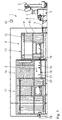
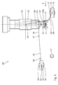
- the schematic structure of an in Fig. 1 illustrated embodiment of a dough processing plant 1 is basically from the EP 1 600 058 A2 known.
- the dough processing equipment 1 has a base frame 1a and comprises a kneader 2 for kneading dough.
- the kneading device 2 has a lifting and pivoting trough 3, which in Fig. 1 is shown in both a kneading and in a raised and pivoted delivery position. In the delivery position of the trough 3 is below this a feed hopper 4 a portioning and rotary device 5.
- the portioning and rotary device 5 comprises a round knitting station 6. This is by a multi-beam transfer conveyor belt 7 with a modular constructed fermenting and shaping device 8 connected.
- the hanger conveyor 10 comprises a plurality of hanger, not shown, for receiving dough, in particular dough pieces.
- the hangers are connected to a conveyor chain 11 which is guided endlessly circulating over a plurality of pulleys 12.
- conveying the conveyor chain 11 runs in sub-modules 13, 14, 15 in a substantially clockwise order.
- a stamping station 16 is provided in the sub-module 15.
- the submodule 15 forms a constituent part of a sprinkling and posthardening device 17.
- the dough pieces are transported along the conveying direction 9 by means of a section of a driven conveyor belt 18, which is preferably designed in multiple lanes.
- the conveyor belt 18 is an example of a dough conveyor for conveying the dough pieces in the conveying direction 9.
- the conveyor belt 18 conveys the dough pieces to be processed in the conveying direction 9 at a predetermined, constant conveying speed.
- the dough pieces are received in Teiglingschalen 18 a, which are taken from the conveyor belt 18 and move with this at the predetermined, constant conveying speed in the conveying direction 9.
- the dough pieces in the embodiment of the dough processing system 1 shown in the conveying direction 9 pass through a plurality of processing stations, to which a stamping station 19 belongs, which in the Fig. 1 is shown very schematically.
- the dough processing equipment 1 is designed to carry out at least sixty-five operations per minute and can be more than sixty-five operations per minute, more than seventy Perform machining operations per minute and also more than eighty machining operations per minute.
- one or more of the processing stations shown schematically may be omitted or replaced by a comparable station.
- the dough pieces arrive after the conveyor belt section 18 on a section of a further driven conveyor belt 20.
- the dough pieces During conveyance on the conveyor belt 20 in the conveying direction 9, the dough pieces pass through a flouring device 21 according to the invention, through which the dough pieces are selectively sprinkled with flour.
- the stub device 22 represents an example of a processing device of the dough processing plant 1 for processing the conveyed on the conveyor belt 18 dough pieces with a processing unit.
- a processing unit is used in the stub device 22 is a Stüpfelech 23
- the a stub tool 24 for staking the dough piece such as a Kaiserstüpfler, has at its lower end.
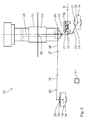
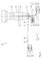
- the punching unit 23 is designed in such a way that during processing, that is to say during the stamping, with the dough piece to be processed relative to the base frame 1 a, which in the Fig. 2 is indicated by two frame strips shown broken, is driven driven in the conveying direction 9.
- the drive motors 27, 28 are designed as servomotors.
- the drive 25 is the actual Stüpfelantrieb the Stüpfel submitted 22 and provides a vertical movement component of the Stüpfeltician 23 relative to the Teiglingschale 18 a.
- the further drive 26 constitutes a ride-on drive, which drives the punching unit 23 in the conveying direction 9 synchronized with the dough-sheeting 18a during the stamping with a travel speed which corresponds to the conveying speed of the conveyor belt 18.
- the Stüpfelantrieb 25 is designed as a rocker, so as a vibratory drive.
- the Mitfahrantrieb 26 is designed as a crank mechanism.
- An amplitude of the oscillating drive 25 can be preset. About the oscillation amplitude can specify a processing depth and in particular a Stüpfelianae.
- the processing depth on the one hand and the processing time on the other hand can be set independently.
- a crank 29 of the stump drive 25 is rotatably connected to a drive shaft 30 of the drive motor 27.
- the crank 29 is pivotally connected to a transmission lever 31, which in turn is connected via a pivot joint 32 with a base body 33 of the Stüpfelech 23.
- the drive shaft 30 extends parallel to the hinge axes of the linkages between the levers 29 and 31 on the one hand and to a pivot axis of the pivot joint 32 on the other.
- a drive shaft 34 of the drive motor 28 is rotatably connected to a crank 35 of the ride-driving 26.
- the crank 35 is pivotally connected to a ride-transfer lever 36, which in turn is connected via a ride-on swivel joint 37 with a fixedly mounted on the base 33 boom 38 of the punch unit 23.
- the drive shaft 34 extends parallel to the hinge axes of the linkages between the levers 35, 36 on the one hand and to a pivot axis of the pivot joint 37 on the other.
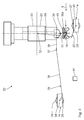
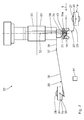
- the Fig. 2 and 3 show a preparation period of the staking, in which the punch tool 24 approaches in the vertical direction of the dough dish 18a. From the momentary position to Fig. 4 A central longitudinal axis 39 of the punch tool 24 is aligned with a central longitudinal axis 40 of the dough sheet shell 18a. Between the current positions after the Fig. 4 and the Fig. 8 the stubbing takes place. During this period of processing, the punching unit 23 moves along with the dough sheet tray 18a in the conveying direction 9 at the predetermined conveying speed of the conveyor belt 18. This ride-on movement with the conveying speed of the conveyor belt 18 is predetermined via the ride-on drive 26.
- the punching tool 24 As soon as after stubbing, driven by the stump drive 25, the punching tool 24 has a sufficiently large vertical distance to the dough dish 18a and thus to the diced dough piece, the punching tool is no longer driven along with the dough dish 18a, but very quickly counter to the conveying direction 9 towards the starting position Beginning of the stubbing in cooperation with the next dough bowl 18a spent. This movement counter to the conveying direction 9 occurs at a significantly higher speed than the absolute amount of the conveying speed of the conveyor belt 18. The processing sequence according to the Fig. 2 to 9 is then repeated for the processing of the dough in the next Teiglingschale 18 a.
- the drive shaft 30 reverses its direction of rotation during processing, depending on whether the punch tool 24 is lowered in the direction of the dough dish 18a or lifted in the opposite direction thereof.
- the movement path of the punching tool 24 is brought about relative to the dough dish 18a in the form of an electronic curve.
- a traveling cutting device as a further possible processing device with corresponding drives.
- the Mitfahrantrieb such a cutting device can be carried out the same as the Mitfahrantrieb 26.
- a cutting drive of such a cutting device can be performed according to the Stüpfelantrieb the Stüpfel worn 22.
- a drive of the conveyor belts 18 and 20 and the Stüpfelantrieb 25 and the ride-driving 26 are controlled by a common control device 41 of the dough processing plant 1, which is shown schematically in the drawing. Details of a synchronization of the respective processing unit for dough conveying can be specified via the control device 41, in particular the number of processing operations per minute or a ride-in period during which the processing unit moves synchronized with the dough piece in the conveying speed.
Abstract
Eine Teigbearbeitungsanlage hat einen Grundrahmen (1a) und mindestens eine angetriebene Teig-Fördereinrichtung (18) zum Fördern zu bearbeitender Teiglinge in einer Förderrichtung (9). Mindestens eine Bearbeitungseinrichtung (22) dient zur Bearbeitung der auf der Teig-Fördereinrichtung (18) geförderten Teiglinge mit einer Bearbeitungseinheit (23). Die Bearbeitungseinheit (23) ist so ausgeführt, dass sie während der Bearbeitung mit dem zu bearbeitenden Teigling relativ zum Grundrahmen (1a) in der Förderrichtung (9) angetrieben verlagert wird. Es resultiert eine Teigbearbeitungsanlage, bei der die Qualität einer Teigling-Bearbeitung auch bei hoher Förderbandgeschwindigkeit gewährleistet bleibt.A dough processing plant has a base frame (1a) and at least one driven dough conveyor (18) for conveying dough pieces to be processed in a conveying direction (9). At least one processing device (22) serves for processing the dough pieces conveyed on the dough conveying device (18) with a processing unit (23). The processing unit (23) is designed such that it is displaced in the conveying direction (9) during processing with the dough piece to be processed relative to the base frame (1a). The result is a dough processing plant, in which the quality of a dough processing is guaranteed even at high conveyor belt speed.
Description
Die vorliegende Patentanmeldung nimmt die Priorität der deutschen Patentanmeldung
Die Erfindung betrifft eine Teigbearbeitungsanlage mit einer Bearbeitungseinrichtung zur Bearbeitung von auf einem Teig-Förderband geförderten Teiglingen mit einer Bearbeitungseinheit.The invention relates to a dough processing plant with a processing device for processing on a dough conveyor conveyed dough pieces with a processing unit.
Eine derartige Teigbearbeitungsanlage ist beispielsweise aus der
Es ist eine Aufgabe der vorliegenden Erfindung, eine Teigbearbeitungsanlage derart weiterzubilden, dass die Qualität einer Teigling-Bearbeitung auch bei hoher Förderbandgeschwindigkeit gewährleistet bleibt.It is an object of the present invention to develop a dough processing plant such that the quality of a dough processing remains guaranteed even at high conveyor belt speed.
Diese Aufgabe ist erfindungsgemäß gelöst durch eine Teigbearbeitungsanlage mit den in Anspruch 1 angegebenen Merkmalen.This object is achieved by a dough treatment plant with the features specified in claim 1.
Erfindungsgemäß wurde erkannt, dass eine während der Stüpfel-Bearbeitung mit dem zu bearbeitenden Teigling in der Förderrichtung angetriebene Bearbeitungseinheit, also eine während der Stüpfel-Bearbeitung mit dem Teigling mitfahrende Bearbeitungseinheit die Möglichkeit schafft, einen für die Stüpfel-Bearbeitung während eines Bearbeitungsvorgangs zur Verfügung stehenden Zeitraum zu verlängern. Der Stüpfelvorgang selbst kann während dieses Zeitraums stattfinden, ohne dass eine Relativbewegung des Teiglings zur Stüpfel-Bearbeitungseinheit längs der Förderrichtung stattfindet. Die Relativbewegung zwischen dem Teigling und der Stüpfel-Bearbeitungseinheit kann daher ausschließlich längs einer Stüpfelrichtung, also längs einer Bearbeitungsrichtung erfolgen, die senkrecht auf der Förderrichtung stehen kann. Auch bei höherer Fördergeschwindigkeit lässt sich im Ergebnis immer die gleiche Stüpfelgeschwindigkeit realisieren, da die mitfahrende Bearbeitungseinheit einen längeren Stüpfel-Zeitraum ermöglicht. Für eine Stüpfel-Bearbeitung, bei der sich die Stüpfel-Bearbeitungseinheit synchron zum Teigling bewegt, steht ein entsprechend verlängerter Zeitraum zur Verfügung.According to the invention, it has been recognized that a processing unit driven in the conveying direction during the stump processing with the dough piece to be processed, ie a processing unit moving along with the dough piece during stump processing, makes it possible to produce a stump processing during a processing operation Extend the period. The Stüpfelvorgang itself can take place during this period without a relative movement of the dough piece to the stump processing unit takes place along the conveying direction. The relative movement between the dough piece and the stump processing unit can therefore take place exclusively along a punching direction, that is to say along a machining direction which can be perpendicular to the conveying direction. Even with a higher conveying speed, the same speed can always be achieved in the result, since the moving processing unit allows a longer stoppage period. For a stump processing, in which the stump processing unit moves synchronously to the dough piece, a correspondingly extended period is available.
Die Teig-Fördereinrichtung kann die zu bearbeitenden Teiglinge in der Fördereinrichtung mit vorgegebener, konstanter Fördergeschwindigkeit fördern. Eine Taktung einer Teigbearbeitung derart, dass die Teig-Fördereinrichtung während eines Bearbeitungstaktes zeitweilig stillsteht, kann vermieden werden. Dies erhöht den Durchsatz der Teigbearbeitungsanlage.The dough conveyor can promote the dough pieces to be processed in the conveyor with a predetermined, constant conveying speed. A timing of a dough processing such that the dough conveyor is temporarily stopped during a processing cycle can be avoided. This increases the throughput of the dough processing plant.
Unerwünschte Einflüsse aufgrund einer zu großen Relativgeschwindigkeit zwischen dem Teigling und der Bearbeitungseinheit längs der Förderrichtung während der Bearbeitung können vermieden werden. Die Fördereinrichtung kann so gestaltet sein, dass hierauf Teiglinge direkt gefördert werden. Alternativ kann die Fördereinrichtung so gestaltet werden, dass hierüber Teigling-Aufnahmen, beispielsweise Teiglingschalen, gefördert werden. Die Fördereinrichtung kann so ausgeführt sein, dass sie die Teiglinge über einen Abschnitt ihres gesamten Förderwegs fördert. Die Fördereinrichtung kann als endlos umlaufende Fördereinrichtung ausgeführt sein. Die Fördereinrichtung kann als Förderband ausgeführt sein.Unwanted influences due to excessive relative speed between the dough piece and the processing unit along the conveying direction during processing can be avoided. The conveyor may be designed so that dough pieces are conveyed directly thereto. Alternatively, the conveyor can be designed so that over this dough pieces, such as dough dishes, are promoted. The conveyor may be configured to convey the dough pieces over a portion of their entire conveying path. The conveyor can be designed as an endless circulating conveyor. The conveyor can be designed as a conveyor belt.
Eine Ausführung nach Anspruch 2 erlaubt einen hohen Durchsatz der Teigbearbeitungsanlage.An embodiment according to
Die Teigbearbeitungsanlage kann mehrreihig, zum Beispiel sechsreihig, achtreihig oder zehnreihig ausgeführt sein.The dough processing plant can be made multi-row, for example, six-row, eight-row or ten-row.
Zwei Antriebe nach Anspruch 3 haben sich zur Vorgabe einer Bewegungsbahn der mitfahrenden Bearbeitungseinheit als besonders geeignet herausgestellt. Beispielsweise eine Bearbeitungstiefe und eine Bearbeitungszeit können unabhängig voneinander eingestellt werden. Die Antriebe können Antriebsmotoren aufweisen, die als Servomotoren ausgeführt sind.Two drives according to
Ein Kurbeltrieb nach Anspruch 4 hat sich zur Vorgabe von Antriebs-Bewegungskomponenten der Bewegungsbahn der Bearbeitungseinheit als besonders geeignet herausgestellt. Es können mehrere, zum Beispiel zwei Kurbeltriebe zum Antrieb der Bearbeitungseinheit vorgesehen sein. Mindestens einer der Antriebe der Teigbearbeitungsanlage kann alternativ oder zusätzlich als Schwingantrieb ausgeführt sein.A crank mechanism according to
Eine variierende Umdrehungsgeschwindigkeit nach Anspruch 5 ermöglicht es, einen zeitlichen Verlauf der Bewegungsbahn der Bearbeitungseinheit während des jeweiligen Bearbeitungsvorgangs fein vorzugeben. Dies kann in Form einer elektronischen Kurve geschehen. Nach erfolgter Bearbeitung kann auf diese Weise die Bearbeitungseinheit z. B. sehr schnell entgegen der Förderrichtung in eine Ausgangsposition zur Bearbeitung des nächsten Teiglings überführt werden.A varying rotational speed according to claim 5 makes it possible to predetermine a time course of the movement path of the processing unit during the respective machining operation. This can be done in the form of an electronic curve. After processing can in this way the processing unit z. B. are transferred very quickly counter to the conveying direction in a starting position for processing the next dough.
Bei einer Ausführung der Bearbeitungseinrichtung mit einer Schneideinrichtung nach Anspruch 6 hat sich das Konzept der mitfahrenden Bearbei-tungseinheit als besonders vorteilhaft herausgestellt. Eine Schneid-Bearbeitungseinheit kann separat zur Stüpfel-Bearbeitungseinheit ausgeführt sein.In one embodiment of the processing device with a cutting device according to
Ein Ausführungsbeispiel der Erfindung wird nachfolgend anhand der Zeichnung näher erläutert. In dieser zeigen:
- Fig. 1
- eine Teigbearbeitungsanlage mit einer Bearbeitungseinrichtung in Form einer Stüpfeleinrichtung in einer Seitenansicht, wobei zum Teil interne Details lediglich schematisch dargestellt sind;
- Fig. 2 bis 9
- in einer Sequenz Momentanpositionen der Bearbeitungseinrichtung, insbesondere Momentanpositionen der Antriebe zur Vorgabe einer Bewegungsbahn der Bearbeitungseinheit relativ zu einer Teiglingaufnahme während der Teigbearbeitung.
- Fig. 1
- a dough processing plant with a processing device in the form of a spotting device in a side view, some internal details are shown only schematically;
- Fig. 2 to 9
- in a sequence instantaneous positions of the processing device, in particular instantaneous positions of the drives for specifying a movement path of the processing unit relative to a Teiglingaufnahme during dough processing.
Der schematische Aufbau einer in
In dem Teilmodul 15 ist eine Stüpfelstation 16 vorgesehen. Das Teilmodul 15 bildet in der gezeigten Ausführungsvariante der Teigbearbeitungsanlage 1 einen Bestandteil einer Bestreuungs- und Nachgäreinrichtung 17. Die Teiglinge werden entlang der Förderrichtung 9 mittels eines Abschnitts eines angetriebenen Förderbands 18 transportiert, welches vorzugsweise mehrspurig ausgebildet ist. Das Förderband 18 ist ein Beispiel für eine Teig-Fördereinrichtung zum Fördern der Teiglinge in der Förderrichtung 9. Das Förderband 18 fördert die zu bearbeitenden Teiglinge in der Förderrichtung 9 mit einer vorgegebenen, konstanten Fördergeschwindigkeit. Die Teiglinge sind in Teiglingschalen 18a aufgenommen, die vom Förderband 18 mitgenommen werden und sich mit diesem mit der vorgegebenen, konstanten Fördergeschwindigkeit in der Förderrichtung 9 bewegen. Entlang des Förderbands 18 passieren die Teiglinge in der gezeigten Ausführungsvariante der Teigbearbeitungsanlage 1 in Förderrichtung 9 mehrere Bearbeitungsstationen, zu denen eine Stüpfelstation 19 gehört, die in der
Die Teigbearbeitungsanlage 1 ist zur Durchführung von mindestens fünfundsechzig Bearbeitungsvorgängen pro Minute ausgeführt und kann mehr als fünfundsechzig Bearbeitungsvorgänge pro Minute, mehr als siebzig Bearbeitungsvorgänge pro Minute und auch mehr als achtzig Bearbeitungsvorgänge pro Minute durchführen.The dough processing equipment 1 is designed to carry out at least sixty-five operations per minute and can be more than sixty-five operations per minute, more than seventy Perform machining operations per minute and also more than eighty machining operations per minute.
Je nach der Art der durch die Teigbearbeitungsanlage 1 geförderten Teiglinge kann eine oder mehrere der schematisch dargestellten Bearbeitungsstationen weggelassen oder durch eine vergleichbare Station ersetzt werden. In dem gezeigten Beispiel der Teigbearbeitungsanlage 1 gelangen die Teiglinge nach dem Förderbandabschnitt 18 auf einen Abschnitt eines weiteren angetriebenen Förderbands 20.Depending on the type of dough conveyed by the dough processing plant 1, one or more of the processing stations shown schematically may be omitted or replaced by a comparable station. In the example of the dough processing system 1 shown, the dough pieces arrive after the
Während der Förderung auf dem Förderband 20 in Förderrichtung 9 passieren die Teiglinge eine erfindungsgemäße Bemehlungsvorrichtung 21, durch welche die Teiglinge selektiv mit Mehl bestreubar sind.During conveyance on the
Die
Die Stüpfeleinheit 23 ist derart ausgeführt, dass sie während der Bearbeitung, also während des Stüpfelns, mit dem zu bearbeitenden Teigling relativ zum Grundrahmen 1a, der in der
Zur Vorgabe einer Bewegungsbahn der Stüpfeleinheit 23 dienen zwei Antriebe 25, 26 mit voneinander unabhängigen Antriebsmotoren 27, 28. Die Antriebsmotoren 27, 28 sind als Servomotoren ausgeführt. Der Antrieb 25 ist der eigentliche Stüpfelantrieb der Stüpfeleinrichtung 22 und sorgt für eine Vertikal-Bewegungskomponente der Stüpfeleinheit 23 relativ zur Teiglingschale 18a. Der weitere Antrieb 26 stellt einen Mitfahrantrieb dar, der die Stüpfeleinheit 23 während des Stüpfelns synchronisiert mit der Teiglingschale 18a mit einer Mitfahrgeschwindigkeit, die der Fördergeschwindigkeit des Förderbands 18 entspricht, in der Förderrichtung 9 antreibt.To specify a movement path of the punching
Der Stüpfelantrieb 25 ist als Schwinge, also als Schwingantrieb, ausgeführt. Der Mitfahrantrieb 26 ist als Kurbeltrieb ausgeführt. Eine Amplitude des Schwingantriebs 25 ist einstellbar vorgebbar. Über die Schwingungsamplitude lässt sich eine Bearbeitungstiefe und insbesondere eine Stüpfeltiefe vorgeben. Über eine Ansteuerung des Kurbelantriebs 26 lässt sich eine Bearbeitungszeitdauer, insbesondere eine Stüpfelzeitdauer vorgeben. Die Bearbeitungstiefe einerseits und die Bearbeitungszeit andererseits können unabhängig voneinander eingestellt werden.The
Eine Kurbel 29 des Stüpfelantriebs 25 ist drehfest mit einer Antriebswelle 30 des Antriebsmotors 27 verbunden. Die Kurbel 29 ist gelenkig mit einem Übertragungshebel 31 verbunden, der wiederum über ein Schwenkgelenk 32 mit einem Grundkörper 33 der Stüpfeleinheit 23 verbunden ist. Die Antriebswelle 30 verläuft parallel zu den Gelenkachsen der Anlenkungen zwischen den Hebeln 29 und 31 einerseits und zu einer Schwenkachse des Schwenkgelenks 32 andererseits.A crank 29 of the
Eine Antriebswelle 34 des Antriebsmotors 28 ist drehfest mit einer Kurbel 35 des Mitfahrantriebs 26 verbunden. Die Kurbel 35 ist gelenkig mit einem Mitfahr-Übertragungshebel 36 verbunden, der wiederum über ein Mitfahr-Schwenkgelenk 37 mit einem fest am Grundkörper 33 montierten Ausleger 38 der Stüpfeleinheit 23 verbunden ist. Die Antriebswelle 34 verläuft parallel zu den Gelenkachsen der Anlenkungen zwischen den Hebeln 35, 36 einerseits und zu einer Schwenkachse des Schwenkgelenks 37 andererseits.A
Die Momentansequenzen der
Die
Sobald nach dem Stüpfeln, angetrieben über den Stüpfelantrieb 25, das Stüpfelwerkzeug 24 einen ausreichend großen Vertikalabstand zur Teiglingschale 18a und damit zum gestüpfelten Teigling hat, wird das Stüpfelwerkzeug nicht weiter mit der Teiglingschale 18a mitgefahren, sondern sehr schnell entgegen der Förderrichtung 9 hin zur Ausgangsposition zu Beginn des Stüpfelns in Zusammenwirkung mit der nächsten Teiglingschale 18a verbracht. Diese Bewegung entgegen der Förderrichtung 9 geschieht mit deutlich höherer Geschwindigkeit als der Absolutbetrag der Fördergeschwindigkeit des Förderbandes 18. Die Bearbeitungssequenz nach den
Während einer gesamten Periode der Bearbeitungssequenz der Stüpfeleinrichtung 22 kann während eines vergleichsweise großen Zeitraums ein Mitfahren des Stüpfelwerkzeugs mit der Teiglingschale 18a und damit ein entsprechend langer Stüpfelzeitraum, während dem das Stüpfelwerkzeug 24 mit dem Teigling in der Teiglingschale 18a in Kontakt steht, gewährleistet sein. Dieser Stüpfelzeitraum ist aufgrund der mitfahrenden Stüpfeleinheit 23 also deutlich länger als bei einer konventionellen Stüpfeleinrichtung 22.During a whole period of the processing sequence of the
Um die Bewegungsbahn nach den
Die Antriebswelle 30 kehrt während der Bearbeitung ihre Drehrichtung um, je nachdem, ob das Stüpfelwerkzeug 24 in Richtung auf die Teiglingschale 18a abgesenkt oder in Gegenrichtung von dieser abgehoben wird.The
Über die Variation der Umdrehungsgeschwindigkeiten der beiden Antriebsmotoren 27, 28 wird die Bewegungsbahn des Stüpfelwerkzeugs 24 relativ zur Teiglingschale 18a in Form einer elektronischen Kurve herbeigeführt.About the variation of the rotational speeds of the two
Anstelle oder alternativ zu einer entsprechend der vorstehenden Beschreibung mitfahrenden Stüpfeleinrichtung kann mit entsprechenden Antrieben auch beispielsweise eine mitfahrende Schneideinrichtung als weitere mögliche Bearbeitungseinrichtung realisiert sein. Der Mitfahrantrieb einer solchen Schneideinrichtung kann genauso ausgeführt sein wie der Mitfahrantrieb 26. Ein Schneidantrieb einer solchen Schneideinrichtung kann entsprechend dem Stüpfelantrieb der Stüpfeleinrichtung 22 ausgeführt sein.Instead of or as an alternative to a punching device moving along in accordance with the above description, it is also possible to implement, for example, a traveling cutting device as a further possible processing device with corresponding drives. The Mitfahrantrieb such a cutting device can be carried out the same as the
Ein Antrieb der Förderbänder 18 und 20 sowie der Stüpfelantrieb 25 und der Mitfahrantrieb 26 werden über eine gemeinsame Steuereinrichtung 41 der Teigbearbeitungsanlage 1 gesteuert, die in der Zeichnung schematisch dargestellt ist. Über die Steuereinrichtung 41 können Details einer Synchronisierung der jeweiligen Bearbeitungseinheit zur Teiglingsförderung vorgegeben werden, insbesondere die Anzahl der Bearbeitungsvorgänge pro Minute oder auch ein Mitfahrzeitraum, während der die Bearbeitungseinheit mit dem Teigling in der Fördergeschwindigkeit synchronisiert mitfährt.A drive of the
Claims (6)
Applications Claiming Priority (1)
| Application Number | Priority Date | Filing Date | Title |
|---|---|---|---|
| DE102015217192.2A DE102015217192A1 (en) | 2015-09-09 | 2015-09-09 | Teigbearbeitungsanlage |
Publications (1)
| Publication Number | Publication Date |
|---|---|
| EP3141126A1 true EP3141126A1 (en) | 2017-03-15 |
Family
ID=56853478
Family Applications (1)
| Application Number | Title | Priority Date | Filing Date |
|---|---|---|---|
| EP16186598.5A Withdrawn EP3141126A1 (en) | 2015-09-09 | 2016-08-31 | Dough processing facility |
Country Status (2)
| Country | Link |
|---|---|
| EP (1) | EP3141126A1 (en) |
| DE (1) | DE102015217192A1 (en) |
Citations (6)
| Publication number | Priority date | Publication date | Assignee | Title |
|---|---|---|---|---|
| US5006358A (en) * | 1988-05-09 | 1991-04-09 | Ribio Manuel J | Method of making tortillas |
| WO1998023168A1 (en) * | 1996-11-27 | 1998-06-04 | Mars, Incorporated | Ultrasonic forming of confectionery products |
| EP1296137A2 (en) | 2001-09-25 | 2003-03-26 | A. FRITSCH GMBH & CO. KG | Dough measurement for monitoring and controlling the dough quality in automatic dough processing |
| US20040191378A1 (en) * | 2003-03-25 | 2004-09-30 | Golby Adrian Barry | System and method for processing tortillas |
| EP1600058A2 (en) | 2004-05-29 | 2005-11-30 | Neuenkirchener Maschinenfabrik Emil Kemper GmbH | Process and apparatus for forming a ready-to-bake, connectionless dough ring, and process for making a ring-shaped bakery product from such a pre-shaped dough ring. |
| EP1853117B1 (en) | 2005-02-25 | 2011-03-23 | Fritsch GmbH | Method for producing knotted dough preforms from dough strands and device for the automated production of knotted dough products |
-
2015
- 2015-09-09 DE DE102015217192.2A patent/DE102015217192A1/en not_active Ceased
-
2016
- 2016-08-31 EP EP16186598.5A patent/EP3141126A1/en not_active Withdrawn
Patent Citations (6)
| Publication number | Priority date | Publication date | Assignee | Title |
|---|---|---|---|---|
| US5006358A (en) * | 1988-05-09 | 1991-04-09 | Ribio Manuel J | Method of making tortillas |
| WO1998023168A1 (en) * | 1996-11-27 | 1998-06-04 | Mars, Incorporated | Ultrasonic forming of confectionery products |
| EP1296137A2 (en) | 2001-09-25 | 2003-03-26 | A. FRITSCH GMBH & CO. KG | Dough measurement for monitoring and controlling the dough quality in automatic dough processing |
| US20040191378A1 (en) * | 2003-03-25 | 2004-09-30 | Golby Adrian Barry | System and method for processing tortillas |
| EP1600058A2 (en) | 2004-05-29 | 2005-11-30 | Neuenkirchener Maschinenfabrik Emil Kemper GmbH | Process and apparatus for forming a ready-to-bake, connectionless dough ring, and process for making a ring-shaped bakery product from such a pre-shaped dough ring. |
| EP1853117B1 (en) | 2005-02-25 | 2011-03-23 | Fritsch GmbH | Method for producing knotted dough preforms from dough strands and device for the automated production of knotted dough products |
Also Published As
| Publication number | Publication date |
|---|---|
| DE102015217192A1 (en) | 2017-03-09 |
Similar Documents
| Publication | Publication Date | Title |
|---|---|---|
| EP0635340B1 (en) | Automatic cutting device | |
| EP2226170B1 (en) | Supply chain frame for automatic slicing machines | |
| EP0226925B1 (en) | Portioning device | |
| DE1964331B2 (en) | Device for making gloves from latex | |
| DE2116632A1 (en) | Device for successively conveying small, elongated objects or workpieces | |
| EP3649863B1 (en) | Lifting tipper with discharge device for compact masses of foodstuffs, in particular bar masses or biscuit doughs | |
| DE3900414C2 (en) | ||
| EP3680032A1 (en) | Sorter | |
| EP3141126A1 (en) | Dough processing facility | |
| DE1215073B (en) | Automatic bakery plant for the production of baked goods, especially bread and rolls | |
| DE3700091C1 (en) | Dough-plaiting apparatus | |
| EP1372400A2 (en) | Device for forming a dough strand | |
| DE19831253A1 (en) | Machine manufacture of Central Anatolian pastry-envelope delicacies | |
| EP3078270A1 (en) | Device for continuous folded deposition of dough on a conveyor | |
| DE202009012319U1 (en) | Device for covering at least a portion of a foodstuff | |
| EP2193725B1 (en) | Transport unit and peeling device for elongated peeled goods | |
| DE2249383C3 (en) | Dough processing plant | |
| DE2136053B2 (en) | Machine for making layered biscuits | |
| EP1767475B1 (en) | Device for pushing articles from a conveyor belt to another | |
| EP2225946A2 (en) | Device for handling food products | |
| DE1258362B (en) | Device for transferring active blades brought up on garden boards to a downstream baking belt of an oven | |
| EP2298078A2 (en) | Apparatus for working dough pieces | |
| EP3600802B1 (en) | Device and method for slicing and portioning of food articles | |
| CH670933A5 (en) | ||
| DE2315770C3 (en) | Device for conveying and aligning eggs and for transferring the eggs into the gripper units of an egg-breaking machine |
Legal Events
| Date | Code | Title | Description |
|---|---|---|---|
| PUAI | Public reference made under article 153(3) epc to a published international application that has entered the european phase |
Free format text: ORIGINAL CODE: 0009012 |
|
| AK | Designated contracting states |
Kind code of ref document: A1 Designated state(s): AL AT BE BG CH CY CZ DE DK EE ES FI FR GB GR HR HU IE IS IT LI LT LU LV MC MK MT NL NO PL PT RO RS SE SI SK SM TR |
|
| AX | Request for extension of the european patent |
Extension state: BA ME |
|
| 17P | Request for examination filed |
Effective date: 20170914 |
|
| RBV | Designated contracting states (corrected) |
Designated state(s): AL AT BE BG CH CY CZ DE DK EE ES FI FR GB GR HR HU IE IS IT LI LT LU LV MC MK MT NL NO PL PT RO RS SE SI SK SM TR |
|
| 17Q | First examination report despatched |
Effective date: 20190123 |
|
| STAA | Information on the status of an ep patent application or granted ep patent |
Free format text: STATUS: THE APPLICATION HAS BEEN WITHDRAWN |
|
| 18W | Application withdrawn |
Effective date: 20190624 |