EP0226925A2 - Portioning device - Google Patents
Portioning device Download PDFInfo
- Publication number
- EP0226925A2 EP0226925A2 EP86117031A EP86117031A EP0226925A2 EP 0226925 A2 EP0226925 A2 EP 0226925A2 EP 86117031 A EP86117031 A EP 86117031A EP 86117031 A EP86117031 A EP 86117031A EP 0226925 A2 EP0226925 A2 EP 0226925A2
- Authority
- EP
- European Patent Office
- Prior art keywords
- knife
- machine according
- nozzle
- plane
- working
- Prior art date
- Legal status (The legal status is an assumption and is not a legal conclusion. Google has not performed a legal analysis and makes no representation as to the accuracy of the status listed.)
- Granted
Links
Images


Classifications
-
- B—PERFORMING OPERATIONS; TRANSPORTING
- B26—HAND CUTTING TOOLS; CUTTING; SEVERING
- B26D—CUTTING; DETAILS COMMON TO MACHINES FOR PERFORATING, PUNCHING, CUTTING-OUT, STAMPING-OUT OR SEVERING
- B26D5/00—Arrangements for operating and controlling machines or devices for cutting, cutting-out, stamping-out, punching, perforating, or severing by means other than cutting
- B26D5/02—Means for moving the cutting member into its operative position for cutting
- B26D5/04—Means for moving the cutting member into its operative position for cutting by fluid pressure
Definitions
- the invention relates to a portioning machine with a filling pump and at least one outlet nozzle connected to it.
- portioning machines are mainly used in the food industry.
- a particular area of application is the meat processing industry, where the meat and possibly also bones and the like. is processed into a portionable mass by means of suitable comminution machines. If this mass leaves the outlet nozzle without a sausage casing, it must be stiff enough that it does not fall apart under its own weight. If this is guaranteed, a strand of mass is created, which can be divided into individual portions using this portioning machine.
- a very special area of application can be, for example, the production of so-called "cevapcici".
- the object is to design a portioning machine of the type described at the outset in such a way that the mass strand emerging from the nozzle mouth can be divided into sections of a predetermined length with the aid of this, without causing any significant deformation of the ends.
- the portioning machine should in particular be able to work continuously.
- the portioning machine is designed in accordance with the preamble of claim 1 in accordance with the characterizing part of this claim.
- the knife can be moved at predetermined, preferably adjustable, time intervals, in particular it can be moved.
- the knife in its infeed end position can be lifted off the nozzle mouth and can be reset against the nozzle mouth before the cutting movement begins.
- lifting the knife that can be moved along the nozzle mouth when cutting at the end of the cutting process one can work with a continuously escaping mass flow without having to put up with a deformation of the portion ends formed during cutting.
- this lifting of the knife from the nozzle mouth which can also give the separated portion an impulse in the direction of removal, requires timely approaching the nozzle mouth in order to be able to slide directly along the latter during the next working stroke.
- the knife is pivotally mounted on a sliding member about an axis running in its longitudinal direction and perpendicular to the infeed direction and is connected to a pivot drive. Due to this pivotable mounting of the knife, it can be fixed in place with respect to the nozzle and still achieve the necessary lifting and infeed movement.
- the pivot drive has a, in particular pneumatic, working cylinder, which at the same time forms a knife displacement drive, and that the working direction of the working piston runs approximately parallel to the working direction of the sliding member, the working piston having a swivel joint with a tab or the like.
- the knife or a knife holder is coupled.
- the axes of rotation of the swivel joint and the knife or a knife holder run parallel to one another.
- the rotary movement of the knife and its infeed movement do not necessarily have to take place separately, rather they can be at least partially superimposed.
- the shifting movement may only begin when the knife has reached the nozzle mouth or its intended shifting plane and has not yet reached the mass flow.
- a preferred embodiment of the invention is characterized in that the tab or the like is extended beyond the swivel joint of the working piston and the extension piece carries a stop element which is displaceably and rotatably mounted in an elongated hole of a control member, the elongated hole being parallel to Working cylinder and extends to the longitudinal axis of the sliding member.
- the knife can be swiveled away from the nozzle mouth in a simple manner, utilizing the displacement movement of the working piston.
- the working piston is displaced in the opposite direction, this causes a torque on the knife or a knife holder, which lifts the knife from the nozzle mouth, with a small pivoting movement about the pivot axis of the knife or his knife holder takes place on the sliding link.
- the cylinder of the working piston and the control member can be pivoted about parallel axes, which are also parallel to the pivot axis of the knife and the articulation axis of the Tab or the like run.
- the working cylinder and that In this way, control elements can oscillate around their suspension axes to the extent necessary.
- the knife is designed as a flat, in particular strip-like knife, the plane of which, when cutting, is inclined to the plane of the nozzle mouth or mouths. In this way, a particularly good, deformation-free or at least low-deformation cut is obtained.
- This knife can also be used to cut two or more strands running side by side at the same time.
- the geometric axis of the sliding member is expediently located approximately in the plane of the nozzle mouth or mouths. This means that the direction of displacement of the sliding member runs parallel to the plane of the nozzle mouth, while the plane of the knife includes a, preferably acute, angle with that of the nozzle mouth. This also contributes to the good work result and enables the mass to flow continuously even during the cutting process.
- a further embodiment of the invention is that an imaginary plane runs approximately perpendicular to the plane of the nozzle mouth through the geometric axes of the displacement member, the working piston and the control member. In this way, the knife can be moved back and forth on a circular path without tilting.
- the plane of the nozzle mouth is inclined to the longitudinal axis of the nozzle or nozzles.
- the inclination of the nozzle mouth is now chosen so that when cutting the plane of the knife, which, as I said, is also inclined to the geometric axis of the sliding member, is approximately perpendicular to the geometric axis of the outlet nozzle.
- the inclinations are chosen so that the knife moves when gliding along the oblique nozzle mouth both transversely to the mass strand and in its För derrichtun g .
- nozzle is located at the outlet of a metering device, in particular a gear metering pump.
- a gear metering pump This has a pair of gearwheels in a known manner and the mass to be conveyed is in the tooth gaps when the gearwheels are turned. The mass delivered per unit of time can be varied by changing the gear speed.
- a particularly preferred embodiment of the invention is characterized in that a plurality of gears are attached to a common drive shaft, the gear metering pump set having a plurality of gear pumps arranged next to one another is heard, the outlet nozzles being arranged in series next to each other at q are and a common knife is assigned to all.
- the length of this knife is determined by the number of nozzles and its width in the cutting direction is essentially determined by the thickness of the nozzle mouth.
- Characterized in that all driving gear wheels of the metering gear pumps arranged side by side sit on a common drive shaft and are thus driven by a common, in particular electrical, motor, with the same nozzle dimensioning, an equally strong mass strand emerges at the same speed from each nozzle. With each knife stroke, a portion number corresponding to the number of dosing pumps is created.
- a further embodiment of the invention is characterized in that the inlets of the gear metering pumps are connected to one another via a cross distributor, the inlet connection or the like of which is connected in terms of flow to the filling pump, so that the medium can be supplied to all the metering pumps via a single filling pump .
- Another preferred variant of the invention is by a transport that can be passed underneath the nozzle orifices link for the cut portions. It must be so arranged, in particular in terms of height, that on the one hand the portions are not deformed when placed on it, and on the other hand the escape of the mass flow and the cutting off by the transport member is not impaired.
- the transport member is designed in a particularly advantageous manner as a web that can be unwound from a roll, in particular made of paper. This paper web can then later be divided into transportable or dispatchable units with the portions lying thereon.
- the web of paper or the like is supported in a further embodiment of the invention on an endless conveyor belt, which is expediently adjustable in height, thereby adapting the height to the nozzle orifices and with an inclined course of the conveyor belt plane to the imaginary plane through the geometric axes of the sausage-shaped portions To allow variation of the portion length in a certain order.
- Another part of the invention results from the fact that the knife can be adjusted by means of a preferably adjustable clock device, in particular electropneumatically.
- the portion size corresponds to the set delivery rate of the filling pump between two pulses divided by the number of nozzles.
- the filling material to be divided into portions is introduced into the funnel 1 of the device 2.
- the device 2 contains at least one filling pump 3.
- at least one comminution device can also be installed in the device 2, which comminutes the material introduced into the hopper 1 to the desired degree of fineness, if necessary.
- the material conveyed by the filling pump 3 reaches a gear metering pump set 6.
- This is preceded by a transverse distributor 7, the connecting flange 8 of which is tightly connected to the connecting line 5.
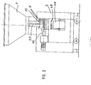
- Each gear metering pump of the metering pump set 6 has an outlet nozzle 9. In FIG. 2 nine such nozzles are shown. 3, the metering pump set consists of fourteen metering pumps 10.
- metering pumps 10 can vary within wide limits. The smallest unit has only a single metering pump, the inlet of which is then connected directly to the connecting line 5. Furthermore, it follows from Fig. 3 that 10 disk-like intermediate pieces 11 of different thickness can be used between the individual metering pumps. These not only set the side distance between the individual outlet nozzles 9, but can also serve as part of the pump housing.
- each nozzle mouth 12 is cut off or sheared off with the aid of a resettable and resettable knife 3 at the predetermined time, as a result of which the strand emerging from the nozzle, for example from stiff sausage or meat sausage meat, into individual more or less short or long Servings is divided.
- the knife thickness is comparatively small and its width is set according to the diameter of the nozzle mouth.
- the length of the knife depends on the width of the gear metering pump set 6 in the direction of the geometric axis 14 of the drive shaft 15 for, for example, all upper gear wheels 16 measured. In the latter case, the driving wheel is designated 16 and the driven wheel 17.
- the operation of such gear metering pumps is known and therefore does not need to be explained in more detail.
- the material is conveyed through the tooth gaps 18 and 19 to the outlet nozzle 9. Accordingly, all emerging mass strands are cut through with a single knife stroke.
- the knife 13 can be set in the direction of the arrow 20 and can be reset in the opposite direction. During cutting, it slides along the nozzle mouth 12, the strands being sheared off at high speed. This will be explained in more detail below.
- the knife 13 is pivotable about an axis 21 extending in its longitudinal direction and perpendicular to the feed direction 20 a sliding member 22 mounted and connected to a rotary drive 23.
- the exemplary embodiment also provides a knife holder 24, on which the knife, in particular replaceable, is held. Accordingly, in the exemplary embodiment, the knife is indirectly pivotably mounted on the slide member 22 via the knife holder 24.
- the swivel drive 23 has a, in particular pneumatic re, cylinder 25. This is advantageously a knife displacement drive at the same time.
- the working direction of the working piston 26 of this working cylinder 25 runs parallel to the working direction of the sliding member or its guide bearing 27.
- the working piston 26 is coupled via a swivel joint 28 with a tab 29 of the knife holder 24. This tab is extended beyond the swivel joint 28, the extension piece 30 carrying a stop element 31, for example bolt-shaped.
- the stop element 31 engages in an elongated hole 32 of a control member 33 and is displaceable therein in the direction of the double arrow 34 and rotatable about its axis.
- the elongated hole and in particular also the entire control member 33 extend parallel to the working cylinder 25 or displacement member 22, i.e. the geometrical axes of these three elements run parallel and preferably in a common plane. This is otherwise perpendicular to a plane through the knife 13 and all nozzle orifices.
- the axis 21 and the axis of the swivel joint 28 lie on a common imaginary axis that is laid to the geometric axes of the working cylinder and the displacement member Level, while due to the inclination of the tab 29 with its extension piece 30, the stop element 31 is removed from this imaginary plane and in the direction of the articulation axis 35 of the control member 33 on a beam 37.
- the working piston is also limited by an axis 36 Entirely pivoted.
- the lower end of the elongated hole 32 in the drawing forms a stop 38 for the stop element 31. It follows that the stop element 31 is at its greatest distance from the stop 38 in the starting position of the knife 13, that is to say in the retracted end position of the working piston 26. Starting from the upper end position shown in FIG. 4 in the direction of arrow 39, the knife 13 can be pivoted about the axis 23 towards the nozzle mouth 12. This is done automatically with the help of the rotary actuator 23 or more specifically the feed motion of the working piston 26. As soon as namely the working piston in the direction of the arrow 2 O is extended from its cylinder 40, acts on the knife holder 24 and hence to the knife 13 a torque in the direction of arrow 39.
- the working piston 26 of the swivel drive 23, which is also a knife drive, is extended further, this leads to the shearing off of the emerging strand and to the formation of a portion 43 or, in the case of several nozzles, to a corresponding number of portions.
- the stop element 31 lies against the stop 38.
- the extension piece 30 is pivoted clockwise around the stop element 31. This leads to the lifting of the knife 13 from the nozzle mouth 12. If the working piston 26 is now raised by reversing the, in particular pneumatic, double-acting working cylinder 25 against the arrow 20, i.e.
- the portion 43 or the portion group is placed on a transport member 45 that can be moved past beneath the nozzle orifices 12. This is preferably a web 47 that can be unwound from a roll 46, in particular a paper web.
- the portion of the transport member 45 to be covered with the portions 43 rests on the upper run of an endless conveyor belt 48.
- the height 49 of the conveyor belt 48 and in particular its upper run 50 can be set within predetermined limits. 1 that both the device 2 and the associated device 51 with the gear metering pump set 6 and the cutting device can be moved.
- a braking or locking device 52 ensures that the correct alignment with respect to the conveyor belt 48 is maintained.
- controller 53 By means of a controller 53, the conveying of the goods to be divided into portions and the feed movement of the cutting knife 13 are controlled so that the filling pump 3 can work continuously and the gearwheel -Dosing pump set 6 the correct amount is supplied, the cutting process should take place so that the resulting rear and front ends of the portions and the portions themselves are not deformed.
- the controller 53 also serves other purposes, for example, the correct operation of a Zerkleintiksein direction of the device 2.
- the portion size can be set on the controller 53. It is dependent on the flow rate, for example in the connecting line 5, and the time interval and between two working movements of the cutting knife 13.
Landscapes
- Physics & Mathematics (AREA)
- Fluid Mechanics (AREA)
- Life Sciences & Earth Sciences (AREA)
- Forests & Forestry (AREA)
- Engineering & Computer Science (AREA)
- Mechanical Engineering (AREA)
- Formation And Processing Of Food Products (AREA)
- Crushing And Pulverization Processes (AREA)
- Perforating, Stamping-Out Or Severing By Means Other Than Cutting (AREA)
Abstract
Um eine, insbesondere steife, nicht in eine Wursthülle eingefüllte Masse, welche aus wenigstens einer Düse (9) austritt, in vorzugsweise gleiche Portionen unterteilen zu können, bringt man im Bereich der Düsenmündung (12) ein zu- und rückstellbares Messer (13) an. Es ist mit Hilfe eines Arbeitszylinders (25) verschiebbar, der gleichzeitig Teil eines Schwenkantriebs (23) ist. Mit diesem Schwenkantrieb kann man das Messer (13) nach Beendigung des Schneidvorgangs von der Düsenmündung (12) abheben und vor Beginn des Schneidvorgangs weider daran anlegen. Dadurch kann bei kontinuierlichem Ausstoß des Gutes aus der Dosierpumpe (10), insbesondere aber eines Zahnrad-Dosierpumpensatzes (6), mit einer ganzen Reihe solcher Dosierpumpen, der Schneidvorgang ohne Beeinträchtigung der Form der Portionen (43), in inbesonderen gleichen, vorzugsweise vorgewählten, regelmäßigen Abständen durchgeführt werden. Den Dosierpumpen (10) wird das Gut mit Hilfe einer Füllpumpe (3) zugeführt. Die entstandenen Portionen (43) werden vorteilhafterweise auf einem. Transportglied (45) abgelegt, wobei es sich zweckmäßigerweise um eine Papierbahn handelt.
Description
Die Erfindung bezieht sich auf eine Portioniermaschine mit einer Füllpumpe und mindestens einer damit verbundenen Auslaßdüse. Derartige Portioniermaschinen verwendet man vorwiegend in der Lebensmittelindustrie. Ein besonderes Anwendungsgebiet ist die fleischverarbeitende Industrie, wo das Fleisch und gegebenenfalls auch Knochen u.dgl. mittels geeigneter Zerkleinerungsmaschinen zu einer portionierfähigen Masse verarbeitet wird. Wenn diese Masse die Auslaßdüse ohne Wursthülle verläßt, so muß sie steif genug sein, damit sie nicht unter dem Eigengewicht auseinanderfällt. Wenn dies gewährleistet ist, entsteht ein Strang aus Masse, den man mit Hilfe dieser Portioniermaschine in einzelne Portionen unterteilen kann. Ein ganz spezielles Anwendungsgebiet kann beispielsweise die Herstellung sogenannter "Cevapcici" sein.The invention relates to a portioning machine with a filling pump and at least one outlet nozzle connected to it. Such portioning machines are mainly used in the food industry. A particular area of application is the meat processing industry, where the meat and possibly also bones and the like. is processed into a portionable mass by means of suitable comminution machines. If this mass leaves the outlet nozzle without a sausage casing, it must be stiff enough that it does not fall apart under its own weight. If this is guaranteed, a strand of mass is created, which can be divided into individual portions using this portioning machine. A very special area of application can be, for example, the production of so-called "cevapcici".
Es besteht die Aufgabe, eine Portioniermaschine der eingangs beschriebenen Art so auszubilden, daß mit ihrer Hilfe der aus der Düsenmündung austretende Massestrang in Teilstücke vorgegebener Länge unterteilt werden kann, ohne daß es dabei zu nennenswerten Verformungen der Enden kommt. Die Portioniermaschine sollte insbesondere in der Lage sein, kontinuierlich zu arbeiten.The object is to design a portioning machine of the type described at the outset in such a way that the mass strand emerging from the nozzle mouth can be divided into sections of a predetermined length with the aid of this, without causing any significant deformation of the ends. The portioning machine should in particular be able to work continuously.
Zur Lösung dieser Aufgabe wird erfindungsgemäß vorgeschlagen, daß die Portioniermaschine gemäß dem Oberbegriff des Anspruchs 1 gemäß dem kennzeichnenden Teil dieses Anspruchs ausqebildet ist. Durch die Anbringung eines, insbesondere scharfen, klingenartiqen Messers im Bereich der Düsenmündung, das man möglichst rasch zu stellt, sobald die Masse genügend weit über die Düsenmündung ausgetreten ist und welches man selbstverständlich etwa ebenso schnell wieder zurückzieht, unterteilt man den Massestrang forderungsgemäß in einzelne Portionen. Dabei kann man das Messer unmittelbar entlang der Düsenmündung bewegen, um eine besonders saubere Schnittfläche zu erhalten und den Querschnitt des Massestrangs möglichst nicht zu verändern.To achieve this object, it is proposed according to the invention that the portioning machine is designed in accordance with the preamble of claim 1 in accordance with the characterizing part of this claim. By attaching a, especially sharp, blade-like knife in the area of the nozzle mouth, which should be set as quickly as possible as soon as the mass has escaped sufficiently far over the nozzle mouth and which, of course, can be withdrawn just as quickly, the mass strand is divided into individual portions as required . The knife can be moved directly along the nozzle mouth in order to obtain a particularly clean cut surface and, as far as possible, not to change the cross section of the mass strand.
In der Regel wird man auf gleich große Portionen Wert legen. Dies gilt insbesondere bei fabrikmäßiger Fertigung der Portionen. Aus diesem Grunde ist es sehr vorteilhaft, daß das Messer in vorgeqebenen, vorzugsweise einstellbaren, Zeitabständen bewegbar, insbe sondere verschiebbar ist.As a rule, you will value equal portions. This applies particularly to factory-made portions. For this reason, it is very advantageous that the knife can be moved at predetermined, preferably adjustable, time intervals, in particular it can be moved.
In Weiterbildung der Erfindung wird vorgeschlagen, daß das Messer in seiner Zustellendlage von der Düsenmündung abhebbar und vor Beginn der Schneidbewegung gegen die Düsenmündunq hin rückstellbar ist. Durch das Abheben des beim Schneiden entlang der Düsenmündung bewegbaren Messers am Ende des Schneidvorgangs kann man mit einem kontinuierlich austretenden Massestranq arbeiten, ohne ein Verformen der beim Abschneiden gebildeten Portionsenden in Kauf nehmen zu müssen. Andererseits erfordert dieses Abheben des Messers von der Düsenmündung, welches der abgetrennten Portion zugleich auch noch einen Impuls in Abtransportrichtung vermitteln kann, ein rechtzeitiges Annähern an die Düsenmündung, um beim nächsten Arbeitshub an letzterer unmittelbar entlanggleiten zu können.In a further development of the invention it is proposed that the knife in its infeed end position can be lifted off the nozzle mouth and can be reset against the nozzle mouth before the cutting movement begins. By lifting the knife that can be moved along the nozzle mouth when cutting at the end of the cutting process, one can work with a continuously escaping mass flow without having to put up with a deformation of the portion ends formed during cutting. On the other hand, this lifting of the knife from the nozzle mouth, which can also give the separated portion an impulse in the direction of removal, requires timely approaching the nozzle mouth in order to be able to slide directly along the latter during the next working stroke.
In diesem Zusammenhang ist es besonders zweckmäßig, daß das Messer um eine sich in seiner Längsrichtung und senkrecht zur Zustellrichtung verlaufende Achse schwenkbar an einem Verschiebeglied gelagert und mit einem Schwenkantrieb verbunden ist. Auf grund dieser schwenkbaren Lagerung des Messers kann man dessen Führung gegenüber der Düse ortsfest anbringen und trotzdem die notwendige Abhebe- und Zustellbewegung erzielen.In this context, it is particularly expedient that the knife is pivotally mounted on a sliding member about an axis running in its longitudinal direction and perpendicular to the infeed direction and is connected to a pivot drive. Due to this pivotable mounting of the knife, it can be fixed in place with respect to the nozzle and still achieve the necessary lifting and infeed movement.
Eine weitere Ausgestaltung der Erfindung besteht darin, daß der Schwenkantrieb einen, insbesondere pneumatischen, Arbeitszylinder aufweist, der zugleich einen Messer-Verschiebantrieb bildet, und daß die Arbeitsrichtung des Arbeitskolbens etwa parallel zur Arbeitsrichtung des Verschiebeglieds verläuft, wobei der Arbeitskolben über ein Drehgelenk mit einer Lasche od. dgl. des Messers oder eines Messerhalters gekuppelt ist. Die Drehachsen des Drehgelenks und des Messers oder eines Messerhalters verlaufen parallel zueinander. Des weiteren müssen die Drehbewegung des Messers und seine Zustellbewegung nicht notwendigerweise getrennt ablaufen, vielmehr können sie zumindest teilweise überlagert sein. Andererseits darf aber die Verschiebebewegung erst dann beginnen, wenn das Messer an der Düsenmündung oder seiner vorgesehenen Verschiebeebene angekommen ist und dabei den Massestranq noch nicht erreicht hat.Another embodiment of the invention is that the pivot drive has a, in particular pneumatic, working cylinder, which at the same time forms a knife displacement drive, and that the working direction of the working piston runs approximately parallel to the working direction of the sliding member, the working piston having a swivel joint with a tab or the like. The knife or a knife holder is coupled. The axes of rotation of the swivel joint and the knife or a knife holder run parallel to one another. Furthermore, the rotary movement of the knife and its infeed movement do not necessarily have to take place separately, rather they can be at least partially superimposed. On the other hand, however, the shifting movement may only begin when the knife has reached the nozzle mouth or its intended shifting plane and has not yet reached the mass flow.
Eine bevorzugte Ausführungsform der Erfindung kennzeichnet sich dadurch, daß die Lasche od. dgl. über das Drehgelenk des Arbeitskolbens hinaus verlängert ist und das Verlänqerungsstück ein Anschlagelement trägt, das in einem Langloch eines Steuerglieds verschieb- und drehbar gelagert ist, wobei sich das Langloch parallel zum Arbeitszylinder und zur Längsachse des Verschiebeglieds erstreckt. Mit Hilfe dieser Einrichtung kann man unter Ausnützung der Verschiebbewegung des Arbeitskolbens auf einfache Art und Weise ein Wegschwenken des Messers von der Düsenmündung erreichen. Dies geschieht dann besonders vorteilhaft, wenn sich die Schwenkachsen des Messers oder Messerhalters und der Lasche am Arbeitszylinder in der Ausgangsstellung des Messer etwa in einer gemeinsamen, senkrecht zu den Längsachsen des Verschiebeglieds und des Arbeitsglieds verlaufenden Ebenen befinden und das Steuerglied in der Ausgangslage des Messers von dem als Anschlag dienenden Ende des Langloches einen Maximalabstand aufweist sowie am Ende der Schneidbewegung am Anschlag anliegt. Während des Schneidvorgangs läuft das Anschlagelement entlanq dem Lanqloch und es kommt in Vorschubrichtung gesehen an dessen vorderem oder unterem Ende dann an, wenn der Schneidvorqanq beendet ist. Damit wird dann die weitere Vorschubbewegung nicht nur des Anschlagele ments, sondern auch des Arbeitskolbens und des Messers beendiqt. Wenn daraufhin, beispielsweise durch Druckumsteuerung und Verwendung eines doppelt wirkenden Arbeitszylinders, der Arbeitskolben in Gegenrichtung verschoben wird, so bewirkt dies ein Drehmoment am Messer oder einem Messerhalter, welcher das Messer von der Düsenmündung abhebt, wobei eine kleine Schwenkbewegunq um die Schwenkachse des Messers bzw. seines Messerhalters am Verschiebe glied stattfindet.A preferred embodiment of the invention is characterized in that the tab or the like is extended beyond the swivel joint of the working piston and the extension piece carries a stop element which is displaceably and rotatably mounted in an elongated hole of a control member, the elongated hole being parallel to Working cylinder and extends to the longitudinal axis of the sliding member. With the help of this device, the knife can be swiveled away from the nozzle mouth in a simple manner, utilizing the displacement movement of the working piston. This happens particularly advantageously when the pivot axes of the knife or knife holder and the flap on the working cylinder in the starting position of the knife are approximately in a common plane running perpendicular to the longitudinal axes of the displacement member and the working member and the control member in the starting position of the knife from the end of the elongated hole serving as a stop Has maximum distance and abuts the stop at the end of the cutting movement. During the cutting process, the stop element runs along the longitudinal hole and, viewed in the feed direction, it arrives at its front or lower end when the cutting process has ended. This stops the further feed movement not only of the stop element, but also of the working piston and the knife. If thereupon, for example by pressure reversal and use of a double-acting working cylinder, the working piston is displaced in the opposite direction, this causes a torque on the knife or a knife holder, which lifts the knife from the nozzle mouth, with a small pivoting movement about the pivot axis of the knife or his knife holder takes place on the sliding link.
Um sowohl für die Drehgelenke als auch die Schiebeführung des An schlagelements möglichst enge Toleranzen verwenden zu können, ist es von besonderem Vorteil, daß der Zylinder des Arbeitskolbens und das Steuerglied um parallele Achsen verschwenkbar sind, die auch parallel zur Schwenkachse des Messers und der Anlenkachse der Lasche od. dgl. verlaufen. Der Arbeitszylinder und das Steuerglied können auf diese Weise um ihre Aufhängeachsen im notwendigen Umfange pendeln.In order to be able to use the narrowest possible tolerances for both the rotary joints and the sliding guide of the impact element, it is particularly advantageous that the cylinder of the working piston and the control member can be pivoted about parallel axes, which are also parallel to the pivot axis of the knife and the articulation axis of the Tab or the like run. The working cylinder and that In this way, control elements can oscillate around their suspension axes to the extent necessary.
Das Messer ist in Weiterbildung der Erfindunq als flaches, insbesondere leistenartiges Messer ausgebildet, dessen Ebene beim Schneiden geneigt zur Ebene der Düsenmündung bzw. -mündungen verläuft. Man erhält auf diese Weise einen besonders guten, verformungsfreien oder zumindest verformungsarmen Schnitt. Außerdem können mit diesem Messer auch zwei oder mehrere nebeneinander ablaufende Stränge gleichzeitig abgeschnitten werden.In a further development of the invention, the knife is designed as a flat, in particular strip-like knife, the plane of which, when cutting, is inclined to the plane of the nozzle mouth or mouths. In this way, a particularly good, deformation-free or at least low-deformation cut is obtained. This knife can also be used to cut two or more strands running side by side at the same time.
Die geometrische Achse des Verschiebeglieds ist zweckmäßiqerweise etwa in der Ebene der Düsenmündung bzw. -mündungen gelegen. Dies bedeutet, daß die Verschieberichtung des Verschiebeglieds parallel zur Ebene der Düsenmündung verläuft, während die Ebene des Messers mit derjenigen der Düsenmündung einen, vorzuqsweise spitzen Winkel einschließt. Auch dies trägt zum guten Arbeitsergebnis bei und ermöglicht das kontinuierliche Ausströmen der Masse auch während des Schneidvorgangs.The geometric axis of the sliding member is expediently located approximately in the plane of the nozzle mouth or mouths. This means that the direction of displacement of the sliding member runs parallel to the plane of the nozzle mouth, while the plane of the knife includes a, preferably acute, angle with that of the nozzle mouth. This also contributes to the good work result and enables the mass to flow continuously even during the cutting process.
Eine weitere Ausgestaltung der Erfindung besteht darin, daß eine gedachte Ebene durch die geometrischen Achsen des Verschiebeglieds, des Arbeitskolbens und des Steuerglieds etwa senkrecht zur Ebene der Düsenmündung verläuft. Auf diese Weise kann das Messer verkantungsfrei auf einer Kreisbahn zu und zurückgestellt werden.A further embodiment of the invention is that an imaginary plane runs approximately perpendicular to the plane of the nozzle mouth through the geometric axes of the displacement member, the working piston and the control member. In this way, the knife can be moved back and forth on a circular path without tilting.
Bei einer bevorzugten Ausführungsform der Erfindunq verläuft die Ebene der Düsenmündung geneigt zur Längsachse der Düse oder Dü sen. Das bedeutet, daß die Längsachse der Düse oder Düsen auch geneigt zu den geometrischen Achsen von Verschiebeglied, Arbeits- zylinder und Steuerglied angeordnet ist. Die Neigung der Düsenmündung ist nun so gewählt, daß beim Abschneiden die Ebene des Messers, das ja, wie gesagt, auch geneigt zur geometrischen Achse des Verschiebeglieds angeordnet ist, etwa senkrecht zur geometri schen Achse der Auslaßdüse steht. Des weiteren sind die Neigungen so gewählt, daß sich das Messer beim Gleiten entlang der schrägen Düsenmündung sowohl quer zum Massestrang als auch in dessen För derrichtung bewegt.In a preferred embodiment of the invention, the plane of the nozzle mouth is inclined to the longitudinal axis of the nozzle or nozzles. This means that the longitudinal axis of the nozzle or nozzles also inclined to the geometrical axes of the displacement member, A rbeits- cylinder and the control member is arranged. The inclination of the nozzle mouth is now chosen so that when cutting the plane of the knife, which, as I said, is also inclined to the geometric axis of the sliding member, is approximately perpendicular to the geometric axis of the outlet nozzle. Furthermore, the inclinations are chosen so that the knife moves when gliding along the oblique nozzle mouth both transversely to the mass strand and in its För derrichtun g .
Eine weitere Variante der Erfindung kennzeichnet sich dadurch, daß sich die Düse am Auslaß einer Dosiervorrichtung, insbesondere einer Zahnrad-Dosierpumpe befindet. Diese besitzt in bekannter Weise ein Zahnradpaar und die zu fördernde Masse befindet sich beim Drehen der Zahnräder in den Zahnlücken. Durch Veränderung der Zahnraddrehzahl kann man die pro Zeiteinheit geförderte Masse variieren.Another variant of the invention is characterized in that the nozzle is located at the outlet of a metering device, in particular a gear metering pump. This has a pair of gearwheels in a known manner and the mass to be conveyed is in the tooth gaps when the gearwheels are turned. The mass delivered per unit of time can be varied by changing the gear speed.
Eine besonders bevorzugte Ausgestaltung der Erfindung ist dadurch gekennzeichnet, daß auf einer gemeinsamen Antriebswelle mehrere Zahnräder befestigt sind, die einem mehrere nebeneinander anqeordnete Zahnradpumpen aufweisenden Zahnrad-Dosierpumpensatz ange hören, wobei die Auslaßdüsen in Reihe nebeneinander anqeordnet sind und allen ein gemeinsames Messer zugeordnet ist. Die Länge dieses Messers bestimmt sich nach der Zahl der Düsen und seine Breite in Schneidrichtung gesehen wird im wesentlichen durch die Stärke der Düsenmündung festgelegt. Dadurch, daß alle treibenden Zahnräder der nebeneinander angeordneten Dosier-Zahnradpumpen auf einer gemeinsamen Antriebswelle sitzen und damit von einem gemeinsamen, insbesondere elektrischen, Motor angetrieben werden, tritt bei gleicher Düsendimensionierung aus jeder Düse ein gleich starker Massestrangs gleich schnell aus. Mit jedem Messerhub entsteht damit eine der Dosierpumpenzahl entsprechende Portionszahl.A particularly preferred embodiment of the invention is characterized in that a plurality of gears are attached to a common drive shaft, the gear metering pump set having a plurality of gear pumps arranged next to one another is heard, the outlet nozzles being arranged in series next to each other at q are and a common knife is assigned to all. The length of this knife is determined by the number of nozzles and its width in the cutting direction is essentially determined by the thickness of the nozzle mouth. Characterized in that all driving gear wheels of the metering gear pumps arranged side by side sit on a common drive shaft and are thus driven by a common, in particular electrical, motor, with the same nozzle dimensioning, an equally strong mass strand emerges at the same speed from each nozzle. With each knife stroke, a portion number corresponding to the number of dosing pumps is created.
Zwischen den einzelnen Pumpen des Zahnrad-Dosierpumpensatzes be finden sich, insbesondere im Auslaßbereich, scheibenartige Zwischenstücke, welche den Abstand der Düsen bzw. Düsenmündungen festlegen, und gegebenenfalls gleichzeitig auch die Druckseiten der einzelnen Dosierpumpen gegeneinander abdichten.Between the individual pumps of the gear metering pump set be, particularly in the outlet area, disc-like spacers which define the distance between the nozzles or nozzle orifices and, if appropriate, at the same time also seal the pressure sides of the individual metering pumps against one another.
Eine weitere Ausgestaltung der Erfindung kennzeichnet sich dadurch, daß die Einlässe der Zahnrad-Dosierpumpen über einen Quer verteiler miteinander verbunden sind, dessen Einlaßstutzen od. dgl. mit der Füllpumpe strömungsmäßig verbunden ist, so daß das Medium allen Dosierpumpen über eine einzige Füllpumpe zugeführt werden kann.A further embodiment of the invention is characterized in that the inlets of the gear metering pumps are connected to one another via a cross distributor, the inlet connection or the like of which is connected in terms of flow to the filling pump, so that the medium can be supplied to all the metering pumps via a single filling pump .
Eine weitere bevorzugte Variante der Erfindung ist durch ein un terhalb der oder den Düsenmündungen vorbeibeweqbares Transportglied für die abgeschnittenen Portionen qekennzeichnet. Es muß so angeordnet, insbesondere in der Höhe so plaziert werden, daß einerseits die Portionen beim Ablegen darauf nicht verformt wer den und andererseits das Austreten des Massestranqs und das Abschneiden durch das Transportglied nicht beeinträchtigt wird.Another preferred variant of the invention is by a transport that can be passed underneath the nozzle orifices link for the cut portions. It must be so arranged, in particular in terms of height, that on the one hand the portions are not deformed when placed on it, and on the other hand the escape of the mass flow and the cutting off by the transport member is not impaired.
Das Transportglied ist in besonders vorteilhafter Weise als von einer Rolle abwickelbare Bahn, insbesondere aus Papier, ausgebildet. Diese Papierbahn kann dann später mit den daraufliegenden Portionen in transport- oder versandfähige Einheiten unterteilt werden. Die Bahn aus Papier od. dgl. ist in weiterer Ausbildung der Erfindung auf einem endlosen Förderband abgestützt, das zweckmäßigerweise höheneinstellbar ist, um dadurch eine Höhenanpassung an die Düsenmündungen und bei geneigtem Verlauf der För derbandebene zur gedachten Ebene durch die geometrischen Achsen der wurstförmigen Portionen eine Variation der Portionslänge in einer bestimmten Größenordnung zu ermöglichen. Ein weiterer Vor teil der Erfindung ergibt sich dadurch, daß das Messer mittels einer vorzugsweise einstellbaren Takteinrichtung, insbesondere elektropneumatisch, zustellbar ist. An den üblicherweise verwendeten Füllmaschinen ist ein solcher Impuls ohne weiteres abnehm bar, da man ihn dort beispielsweise für das Abdrehen der Würste oder das Anbringen eines Clips benötigt. Weil in bevorzugter Wei se mit der erfindungsgemäßen Portioniermaschine ein Portionieren mit kontinuierlich angetriebenen Dosierpumpen möglich ist, reicht ein einziger Impuls für das Schneiden aus und es entfällt dadurch ein zweiter Impuls für eine Pause. Selbstverständlich muß die Füllgeschwindigkeit der Füllpumpe an die austretende Masse der Dosierpumpe oder -pumpen angepaßt werden. Die heute üblichen elektronischen Steuerungen ermöglichen es ohne weiteres, die verschiedenen Vorrichtungen und Aggregate genau aufeinander abzustimmen und den Impulsabstand in Abhängigkeit von der Fördermenge der Dosierpumpen und der gewünschten Portionsgröße genau festzulegen. Insbesondere ist es möglich, an der Füllpumpe ein bestimm tes Gewicht oder eine bestimmte Fördermenge vorzuwählen. Bei Verwendung von beispielsweise 15 Düsen entspricht dann die Portionsgröße der eingestellten Fördermenge der Füllpumpe zwischen zwei Impulsen geteilt durch die Anzahl der Düsen.The transport member is designed in a particularly advantageous manner as a web that can be unwound from a roll, in particular made of paper. This paper web can then later be divided into transportable or dispatchable units with the portions lying thereon. The web of paper or the like is supported in a further embodiment of the invention on an endless conveyor belt, which is expediently adjustable in height, thereby adapting the height to the nozzle orifices and with an inclined course of the conveyor belt plane to the imaginary plane through the geometric axes of the sausage-shaped portions To allow variation of the portion length in a certain order. Another part of the invention results from the fact that the knife can be adjusted by means of a preferably adjustable clock device, in particular electropneumatically. On the commonly used filling machines, such a pulse is easily removable bar, since it is needed there, for example, for twisting off the sausages or attaching a clip. Because a portioning with continuously driven metering pumps is possible in a preferred manner with the portioning machine according to the invention, a single pulse is sufficient for the cutting and it is therefore eliminated a second impulse for a break. Of course, the filling speed of the filling pump must be adapted to the emerging mass of the metering pump or pumps. The electronic controls customary today make it possible without further ado to precisely coordinate the various devices and units and to precisely determine the pulse interval depending on the delivery rate of the metering pumps and the desired portion size. In particular, it is possible to preselect a specific weight or a specific delivery rate on the filling pump. When using, for example, 15 nozzles, the portion size corresponds to the set delivery rate of the filling pump between two pulses divided by the number of nozzles.
Die Erfindung wird nachstehend anhand der Zeichnung näher erläutert.The invention is explained below with reference to the drawing.
Die Zeichnung zeig ein Ausführungsbeispiel der Erfindung. Hierbei stellen dar:
- Fig. 1 Eine Seitenansicht der Maschine,
- Fig. 2 eine Vorderansicht der Maschine in Pfeilrichtung A der Fig. 1 gesehen,
- Fig. 3 eine abgebrochene Draufsicht im Bereich des Dosierpumpensatzes, teilweise geschnitten, Fign.
- 4
bis 7 in etwas schematisierter Darstellung vier verschiedene Phasen der Portionsbildung.
- 1 is a side view of the machine,
- 2 is a front view of the machine in the direction of arrow A of FIG. 1,
- 3 shows a broken top view in the area of the metering pump set, partly in section, Fig.
- 4 to 7 in a somewhat schematic representation four different phases of portion formation.
In den Trichter 1 der Vorrichtung 2 wird das in Portionen zu unterteilende Füllgut eingebracht. Die Vorrichtung 2 enthält zumindest eine Füllpumpe 3. Darüber hinaus kann in die Vorrichtung 2 auch noch wenigstens eine Zerkleinerungseinrichtung eingebaut sein, welche das in den Trichter 1 eingebrachte Gut gegebenenfalls auf den gewünschten Feinheitsgrad zerkleinert. über den Auslaß 4 und eine Verbindungsleitung 5 gelangt das von der Füllpumpe 3 geförderte Gut zu einem Zahnrad-Dosierpumpensatz 6. Diesem ist ein Querverteiler 7 vorgeschaltet, dessen Anschlußflansch 8 mit der Verbindungsleitung 5 dicht verbunden ist. Jede Zahnrad-Dosierpumpe des Dosierpumpensatzes 6 besitzt eine Auslaßdüse 9. In Fig. 2 sind neun derartige Düsen eingezeichnet. Gemäß Fig. 3 besteht der Dosierpumpensatz aus vierzehn Dosierpumpen 10. Damit soll zum Ausdruck gebracht werden, daß die Zahl der Dosierpumpen 10 innerhalb weiter Grenzen variieren kann. Die kleinste Einheit weist lediglich eine einzige Dosierpumpe auf, deren Einlaß dann unmittelbar an die Verbindungsleitung 5 angeschlossen wird. Des weiteren ergibt sich aus Fig..3, daß zwischen den einzelnen Dosierpumpen 10 scheibenartige Zwischenstücke 11 unterschiedlicher Dicke eingesetzt sein können. Diese legen nicht nur den Seiten abstand der einzelnen Auslaßdüsen 9 fest, sondern können auch als Teil des Pumpengehäuses dienen.The filling material to be divided into portions is introduced into the funnel 1 of the
Das aus jeder Düsenmündung 12 austretende Gut wird mit Hilfe eines zu- und rückstellbaren Messers 3 zur vorbestimmten Zeit abge schnitten oder abgeschert, wodurch der aus der Düse austretende Strang, beispielsweise aus steifem Wurst- oder Fleischbrät, in einzelne mehr oder weniger kurze bzw. lange Portionen unterteilt wird. Beispielsweise aus Fig. 4 ersieht man, daß die Messerdicke vergleichweise gering und seine Breite dem Durchmesser der Düsen mündung entsprechend festgelegt ist. Die Länqe des Messers rich tet sich nach der Breite des Zahnrad-Dosierpumpensatzes 6 in Richtung der geometrischen Achse 14 der Antriebswelle 15 für beispielweise alle oberen Zahnräder 16 gemessen. Im letzteren Falle wird also das treibende Rad mit 16 und das getriebene mit 17 bezeichnet. Die Arbeitsweise derartiger Zahnrad-Dosierpumpen ist bekannt und muß aus diesem Grunde nicht näher erläutert werden. Das Gut wird über die Zahnlücken 18 bzw. 19 zur Auslaßdüse 9 gefördert. Demnach werden also mit einem einzigen Messerhub sämtliche austretenden Massestränge durchschnitten.The material emerging from each
Das Messer 13 ist, wie bereits angedeutet, im Sinne des Pfeiles 20 zustellbar und in Gegenrichtung rückstellbar. Während des Schneidens gleitet es entlang der Düsenmündung 12, wobei die Stränge mit hoher Geschwindigkeit abgeschert werden. Im einzelnen wird das nachstehend noch erläutert.As already indicated, the
Das Messer 13 ist um eine sich in seiner Längsrichtung und senkrecht zur Zustellrichtung 20 verlaufende Achse 21 schwenkbar an einem Verschiebeglied 22 gelagert und mit einem Schwenkantrieb 23 verbunden. Das Ausführungsbeispiel sieht noch einen Messerhalter 24 vor, an welchem das Messer, insbesondere auswechselbar, gehalten ist. Demnach wird also beim Ausführungsbeispiel das Messer indirekt über den Messerhalter 24 verschwenkbar am Verschiebeglied 22 gelagert. Der Schwenkantrieb 23 weist einen, insbesonde re pneumatischen, Arbeitszylinder 25 auf. Dieser ist in vorteil hafter Weise zugleich ein Messer-Verschiebeantrieb. Die Arbeits richtung des Arbeitskolbens 26 dieses Arbeitszylinders 25 verläuft parallel zur Arbeitsrichtung des Verschiebeglieds bzw. dessen Führungslager 27. Der Arbeitskolben 26 ist über ein Drehgelenk 28 mit einer Lasche 29 des Messerhalters 24 gekuppelt. Diese Lasche ist über das Drehgelenk 28 hinaus verlängert, wobei das Verlängerungsstück 30 ein, beispielsweise bolzenförmiqes, Anschlagelement 31 trägt.The
Das Anschlagelement 31 greift in ein Langloch 32 eines Steuerglieds 33 ein und ist darin in Richtung des Doppelpfeils 34 verschiebbar und um seine Achse drehbar. Das Langloch und insbeson dere auch das gesamte Steuerglied 33 erstrecken sich parallel zum Arbeitszylinder 25 bzw. Verschiebeglied 22, d.h. die geometrischen Achsen dieser drei Elemente verlaufen parallel sowie vorzugsweise in einer gemeinsamen Ebene. Diese steht im übrigen zu einer durch das Messer 13 und alle Düsenmündungen gelegten Ebene senkrecht.The
In der in Fig. 4 dargestellten Ausgangslage eines Arbeitszyklus des Messers 13, nämlich bei in seiner oberen Endlage befindlichen Stellung das Arbeitskolbens 26, liegen die Achse 21 und die Achse des Drehgelenks 28 auf einer gemeinsamen zu den geometrischen Achsen des Arbeitszylinders und des Verschiebeglieds gelegten gedachten Ebene, während aufgrund der Schrägstellung der Lasche 29 mit ihrem Verlängerungsstück 30 das Anschlagelement 31 von dieser gedachten Ebene entfernt ist und zwar in Richtung auf die Anlenkachse 35 des Steuerglieds 33 an einem Balken 37. An letzterem ist auch der Arbeitskolben mittels einer Achse 36 in begrenztem Umfange schwenkbar gelagert.In the starting position of a working cycle of the
Das in der Zeichnung untere Ende des Langloches 32 bildet einen Anschlag 38 für das Anschlagelement 31. Hieraus folgt, daß das Anschlagelement 31 vom Anschlag 38 in der Ausgangslage des Messers 13, also in der eingezogenen Endstellung des Arbeitskolbeus 26, seinen größten Abstand aufweist. Das Messer 13 ist ausgehend von der in Fig. 4 gezeichneten oberen Endstellung im Sinne des Pfeils 39 um die Achse 23 gegen die Düsenmündung 12 hin verschwenkbar. Dies erfolgt automatisch mit Hilfe des Schwenkantriebs 23 oder genauer gesagt der Zustellbewegung des Arbeitskolbens 26. Sobald nämlich der Arbeitskolben im Sinne des Pfeils 2O aus seinem Zylinder 40 ausgefahren wird, wirkt am Messerhalter 24 und damit auch am Messer 13 ein Drehmoment im Sinne des Pfeils 39. Dadurch legt sich die Messerschneide 41 an der bzw. den Dü senmündungen 12 an und zwar oberhalb der Düsenbohrung 42. Nunmehr ist die in Fig. 5 gezeigte Stellung erreicht. Die Messerebene, welche gemäß Fig. 4 parallel zur Düsenmündung verlief, steht nunmehr winklig zu der bzw. zu den Düsenmündungen 12.The lower end of the
Wenn der Arbeitskolben 26 des Schwenkantriebs 23, der zugleich Messerantrieb ist, weiter ausgefahren wird, so führt dies zum Abscheren des austretenden Stranges und zur Bildung einer Portion 43 bzw. bei mehreren Düsen zu einer entsprechenden Anzahl von Portionen. Sobald das Schneidmesser 13 gemäß Fig. 6 den Strang durchtrennt hat und dabei seine untere Endlage nahezu erreicht hat, liegt das Anschlagelement 31 am Anschlag 38 an. Beim restJichen Abwärtshub wird das Verlängerungsstück 30 im Uhrzeigersinne um das Anschlagelement 31 verschwenkt. Dies führt zum Abheben des Messers 13 von der Düsenmündung 12. Wird nunmehr der Arbeitskolben 26 durch Umsteuern des, insbesondere pneumatischen, doppelt wirkenden Arbeitszylinders 25 entgegen dem Pfeil 20 angehoben, d.h. in den Zylinder 40 wieder eingezogen, so erzeuqt dies ein Drehmoment um die Achse 21 im Sinne des Pfeils 44 (Fig. 7) am Messer bzw. Messerhalter 24 und das Messer bzw. die Messerschneide hebt infolgedessen vom unteren Ende der Düsenmündunq 12 noch weiter ab. Bei weiterer Aufwärtsbewegung des Kolbens 26 wird schließlich wieder die in Fig, 4 dargestellte Ausgangsstellung des Zyklus erreicht. Insbesondere dieses frühe Abheben des Mes sers schon am Ende des Schneidhubes ermöglicht das vorteilhafte Abschneiden bei ständig laufender Füllpumpe.If the working
Die Portion 43 bzw. die Portionsgruppe wird auf einem unterhalb den Düsenmündungen 12 vorbeibewegbaren Transportglied 45 abgelegt. Dabei handelt es sich vorzugsweise um eine von einer Rolle 46 abwickelbare Bahn 47, insbesondere eine Papierbahn. Das mit den Portionen 43 zu belegende bzw. belegte Teilstück des Transportglieds 45 liegt auf dem oberen Trum eines endlosen Förderbands 48 auf. Die Höhe 49 des Förderbands 48 und insbesondere seines oberen Trums 50 ist innerhalb vorgegebener Grenzen einstellbar. Im übrigen ergibt sich aus Fig. 1, daß sowohl die Vorrichtung 2 als auch die damit verbundene Vorrichtung 51 mit dem Zahnrad-Dosierpumpensatz 6 und der Schneideinrichtung fahrbar sind. Eine Brems- oder Feststelleinrichtunq 52 sorgt für die Beibehaltung der korrekten Ausrichtung qegenüber dem Förderband 48. Mittels einer Steuerung 53 wird die Förderung des in Portionen zu unterteilenden Gutes und die Zustellbewegung des Schneidmessers 13 so gesteuert, daß die Füllpumpe 3 kontinuierlich arbeiten kann und dem Zahnrad-Dosierpumpensatz 6 jeweils die korrekte Menge zugeführt wird, wobei der Abschneidevorgang so ablaufen soll, daß die dabei entstehenden hinteren und vorderen Enden der Portionen und auch die Portionen selbst nicht verformt werden. Gegebenenfalls dient die Steuerung 53 auch noch weiteren Zwecken, bei spielsweise der korrekten Arbeitsweise einer Zerkleinerungsein richtung der Vorrichtung 2. Die Portionsgröße kann an der Steue rung 53 eingestellt werden. Sie ist vom Förderstrom, beispiels weise in der Verbindungsleitung 5, und dem Zeitabst and zwischen zwei Arbeitsbewegungen des Schneidmessers 13 abhängig.The
Claims (20)
Applications Claiming Priority (2)
| Application Number | Priority Date | Filing Date | Title |
|---|---|---|---|
| DE3545673 | 1985-12-21 | ||
| DE3545673A DE3545673C2 (en) | 1985-12-21 | 1985-12-21 | Portioning machine |
Publications (3)
| Publication Number | Publication Date |
|---|---|
| EP0226925A2 true EP0226925A2 (en) | 1987-07-01 |
| EP0226925A3 EP0226925A3 (en) | 1989-03-22 |
| EP0226925B1 EP0226925B1 (en) | 1990-11-22 |
Family
ID=6289311
Family Applications (1)
| Application Number | Title | Priority Date | Filing Date |
|---|---|---|---|
| EP86117031A Expired - Lifetime EP0226925B1 (en) | 1985-12-21 | 1986-12-08 | Portioning device |
Country Status (3)
| Country | Link |
|---|---|
| US (1) | US4747767A (en) |
| EP (1) | EP0226925B1 (en) |
| DE (1) | DE3545673C2 (en) |
Cited By (4)
| Publication number | Priority date | Publication date | Assignee | Title |
|---|---|---|---|---|
| EP0473799B1 (en) * | 1990-08-31 | 1993-08-04 | Frisco-Findus Ag | Cutting of meat |
| GB2279236A (en) * | 1993-06-15 | 1995-01-04 | Pj Contracts Limited | Meat substitute manufacturing process and apparatus therefor |
| CN104054791A (en) * | 2013-03-21 | 2014-09-24 | 艾伯特.汉德特曼机器制造有限责任两合公司 | Method For Manufacturing Coextruded Food Products |
| EP3123867A1 (en) * | 2015-07-30 | 2017-02-01 | Albert Handtmann Maschinenfabrik GmbH & Co. KG | Method and device for simplified alignment of a filling machine for sausage production |
Families Citing this family (12)
| Publication number | Priority date | Publication date | Assignee | Title |
|---|---|---|---|---|
| US5046940A (en) * | 1989-06-19 | 1991-09-10 | Automated Machinery Systems, Inc. | Apparatus for dividing and cutting dough |
| US5840345A (en) * | 1995-04-17 | 1998-11-24 | Ayash; Ajwad | Dough transport device |
| US5906297A (en) * | 1996-11-21 | 1999-05-25 | Cole; Russell H. | Multi-outlet depositor |
| US7645128B2 (en) * | 2003-01-20 | 2010-01-12 | De Jong Engineering Elburg B.V. | Dividing device |
| HRP20041038A2 (en) * | 2004-11-04 | 2006-09-30 | Šturman Klaudio | Apparatus for serial production of minced-meat fingers |
| AT503323B1 (en) * | 2005-01-18 | 2008-11-15 | Erema | STRUCTURE MOLDING COMPONENT AND METHOD FOR ACCESSING THE SAME |
| ES2290811T3 (en) * | 2005-04-11 | 2008-02-16 | ALBERT HANDTMANN MASCHINENFABRIK GMBH & CO. KG | DEVICE AND PROCEDURE FOR THE ORDERED DEPOSITION OF PORTIONS OF INDEPENDENT SAUSAGES. |
| DE102007050592A1 (en) * | 2007-10-23 | 2009-04-30 | Rieter Automatik Gmbh | Continuous casting apparatus for producing granules of plastic material and method for their operation |
| WO2013067087A1 (en) * | 2011-11-01 | 2013-05-10 | Somal Hardev S | Fluff pack portioning apparatus |
| EP3424329B1 (en) * | 2017-07-06 | 2021-03-10 | Radie B.V. | Device for providing a dough piece on a movable substrate |
| CN112873319A (en) * | 2021-01-20 | 2021-06-01 | 胡强 | Eucommia bark cleaning and cutting all-in-one machine |
| CN114931659B (en) * | 2022-04-21 | 2023-01-10 | 广州市爱家有方日用品有限公司 | Long-acting deodorant for public toilet and preparation method thereof |
Family Cites Families (11)
| Publication number | Priority date | Publication date | Assignee | Title |
|---|---|---|---|---|
| DE538189C (en) * | 1930-01-31 | 1931-11-11 | Thomas Asum | Pressed yeast dividing device |
| US2090095A (en) * | 1936-09-22 | 1937-08-17 | George K Bainbridge | Candy cutting machine |
| GB712402A (en) * | 1951-04-24 | 1954-07-21 | S B Engineering Company Ltd | Improvements in or relating to the manufacture of plastic material such as ice cream |
| DE1695105U (en) * | 1953-04-07 | 1955-03-17 | Georg Bader | FACILITY FOR THE PRODUCTION OF SMOKED SAUSAGES WITHOUT INTESTINES. |
| GB774347A (en) * | 1954-07-07 | 1957-05-08 | Swan Friteof Anderson | Block forming and wrapping machine |
| US2838012A (en) * | 1955-06-24 | 1958-06-10 | Edward Weidenmiller Co Inc | Cookie forming machine |
| US3019746A (en) * | 1957-09-10 | 1962-02-06 | Facs Mfg Company Inc | Extruding apparatus |
| US3415206A (en) * | 1965-03-31 | 1968-12-10 | Reisman Howard | Pretzel forming |
| US3776671A (en) * | 1970-11-13 | 1973-12-04 | Eskimo Pie Corp | Apparatus for producing confection bars |
| US3782876A (en) * | 1971-12-30 | 1974-01-01 | Reading Pretzel Machinery Co | Extrusion machine for pretzels and the like |
| US4392801A (en) * | 1979-06-13 | 1983-07-12 | Matthew Meyer | Apparatus for manufacturing cheese product |
-
1985
- 1985-12-21 DE DE3545673A patent/DE3545673C2/en not_active Expired - Fee Related
-
1986
- 1986-12-08 EP EP86117031A patent/EP0226925B1/en not_active Expired - Lifetime
- 1986-12-19 US US06/944,666 patent/US4747767A/en not_active Expired - Fee Related
Cited By (8)
| Publication number | Priority date | Publication date | Assignee | Title |
|---|---|---|---|---|
| EP0473799B1 (en) * | 1990-08-31 | 1993-08-04 | Frisco-Findus Ag | Cutting of meat |
| GB2279236A (en) * | 1993-06-15 | 1995-01-04 | Pj Contracts Limited | Meat substitute manufacturing process and apparatus therefor |
| GB2279236B (en) * | 1993-06-15 | 1998-01-21 | Pj Contracts Limited | Meat substitute manufacturing process. |
| CN104054791A (en) * | 2013-03-21 | 2014-09-24 | 艾伯特.汉德特曼机器制造有限责任两合公司 | Method For Manufacturing Coextruded Food Products |
| EP2781160A1 (en) | 2013-03-21 | 2014-09-24 | Albert Handtmann Maschinenfabrik GmbH & Co. KG | Device for producing coextruded food products |
| US9668492B2 (en) | 2013-03-21 | 2017-06-06 | Albert Handtmann Maschinenfabrik Gmbh & Co. Kg | Method for manufacturing coextruded food products |
| EP3123867A1 (en) * | 2015-07-30 | 2017-02-01 | Albert Handtmann Maschinenfabrik GmbH & Co. KG | Method and device for simplified alignment of a filling machine for sausage production |
| US9723848B2 (en) | 2015-07-30 | 2017-08-08 | Albert Handtmann Maschinenfabrik Gmbh & Co. Kg | Method and device for simplified alignment of a filling machine for sausage production |
Also Published As
| Publication number | Publication date |
|---|---|
| US4747767A (en) | 1988-05-31 |
| DE3545673C2 (en) | 1995-12-21 |
| DE3545673A1 (en) | 1987-06-25 |
| EP0226925A3 (en) | 1989-03-22 |
| EP0226925B1 (en) | 1990-11-22 |
Similar Documents
| Publication | Publication Date | Title |
|---|---|---|
| EP0226925B1 (en) | Portioning device | |
| EP0383246B1 (en) | Method and apparatus for supplying given quantities of fibre flock | |
| DE3217643A1 (en) | MIXING AND DEPOSITING DEVICE FOR CONFECTIONERY AND BAKERY PRODUCTS | |
| EP1884489B1 (en) | Device and method for metered output of bulk or free-flowing goods | |
| DE2139131A1 (en) | Process for the meterable requirement of materials and means for executing the process | |
| CH678915A5 (en) | ||
| DE2147280C3 (en) | Device for mixing pourable crops | |
| DE3022631C1 (en) | Agricultural collecting press with filling opening on the underside of the press channel | |
| DE3900414C2 (en) | ||
| DE3402567A1 (en) | DEVICE FOR CUTTING REEL MATERIAL, ESPECIALLY REINFORCED STEEL BARS | |
| DE3803677C2 (en) | ||
| AT394959B (en) | CUTTING SYSTEM FOR CUTTING PIECES OF SELECTABLE LENGTH FROM A GRATING | |
| EP0265783A2 (en) | Feeding device for roller mills, especially with oil-bearing seeds | |
| EP2298078A2 (en) | Apparatus for working dough pieces | |
| DE102008013806B4 (en) | Portioning device (cutting upwards) | |
| DD284150B5 (en) | DEVICE FOR LOOSING SCHUETTGUT | |
| DE3104099A1 (en) | Sausage filling machine with device for forming sausage ends | |
| EP0578938B1 (en) | Cutting device on an extruder for making hollow blocks | |
| DE3244552A1 (en) | Device for discharging sticky material from an upright container | |
| DE162024C (en) | ||
| DE902164C (en) | Device for the production of wax candles | |
| DE625463C (en) | Pouring machine for pouring viscous sugar masses into hollow chocolate bodies | |
| DE925520C (en) | Device for feeding plastic, especially ceramic masses onto the drying system | |
| DE4230684C2 (en) | Device for cutting a sausage chain | |
| DE3408859A1 (en) | Sausage-filling machine with a device for forming the end and a cutting-off device for sausages |
Legal Events
| Date | Code | Title | Description |
|---|---|---|---|
| PUAI | Public reference made under article 153(3) epc to a published international application that has entered the european phase |
Free format text: ORIGINAL CODE: 0009012 |
|
| AK | Designated contracting states |
Kind code of ref document: A2 Designated state(s): FR GB |
|
| PUAL | Search report despatched |
Free format text: ORIGINAL CODE: 0009013 |
|
| AK | Designated contracting states |
Kind code of ref document: A3 Designated state(s): FR GB |
|
| 17P | Request for examination filed |
Effective date: 19890505 |
|
| 17Q | First examination report despatched |
Effective date: 19890913 |
|
| GRAA | (expected) grant |
Free format text: ORIGINAL CODE: 0009210 |
|
| AK | Designated contracting states |
Kind code of ref document: B1 Designated state(s): FR GB |
|
| ET | Fr: translation filed | ||
| GBT | Gb: translation of ep patent filed (gb section 77(6)(a)/1977) | ||
| PLBE | No opposition filed within time limit |
Free format text: ORIGINAL CODE: 0009261 |
|
| 26N | No opposition filed | ||
| PGFP | Annual fee paid to national office [announced via postgrant information from national office to epo] |
Ref country code: FR Payment date: 19941123 Year of fee payment: 9 |
|
| PGFP | Annual fee paid to national office [announced via postgrant information from national office to epo] |
Ref country code: GB Payment date: 19941128 Year of fee payment: 9 |
|
| PG25 | Lapsed in a contracting state [announced via postgrant information from national office to epo] |
Ref country code: GB Effective date: 19951208 |
|
| GBPC | Gb: european patent ceased through non-payment of renewal fee |
Effective date: 19951208 |
|
| PG25 | Lapsed in a contracting state [announced via postgrant information from national office to epo] |
Ref country code: FR Effective date: 19960830 |
|
| REG | Reference to a national code |
Ref country code: FR Ref legal event code: ST |