EP3647767A1 - Isovolumetrisches aufkugeln von roten blutzellen - Google Patents
Isovolumetrisches aufkugeln von roten blutzellen Download PDFInfo
- Publication number
- EP3647767A1 EP3647767A1 EP18203264.9A EP18203264A EP3647767A1 EP 3647767 A1 EP3647767 A1 EP 3647767A1 EP 18203264 A EP18203264 A EP 18203264A EP 3647767 A1 EP3647767 A1 EP 3647767A1
- Authority
- EP
- European Patent Office
- Prior art keywords
- cell
- analysis
- sample
- red blood
- automatic analyzer
- Prior art date
- Legal status (The legal status is an assumption and is not a legal conclusion. Google has not performed a legal analysis and makes no representation as to the accuracy of the status listed.)
- Granted
Links
Images

Classifications
-
- G—PHYSICS
- G01—MEASURING; TESTING
- G01N—INVESTIGATING OR ANALYSING MATERIALS BY DETERMINING THEIR CHEMICAL OR PHYSICAL PROPERTIES
- G01N15/00—Investigating characteristics of particles; Investigating permeability, pore-volume or surface-area of porous materials
- G01N15/10—Investigating individual particles
- G01N15/14—Optical investigation techniques, e.g. flow cytometry
- G01N15/1404—Handling flow, e.g. hydrodynamic focusing
-
- G—PHYSICS
- G01—MEASURING; TESTING
- G01N—INVESTIGATING OR ANALYSING MATERIALS BY DETERMINING THEIR CHEMICAL OR PHYSICAL PROPERTIES
- G01N15/00—Investigating characteristics of particles; Investigating permeability, pore-volume or surface-area of porous materials
- G01N15/10—Investigating individual particles
- G01N15/14—Optical investigation techniques, e.g. flow cytometry
- G01N15/1468—Optical investigation techniques, e.g. flow cytometry with spatial resolution of the texture or inner structure of the particle
- G01N15/147—Optical investigation techniques, e.g. flow cytometry with spatial resolution of the texture or inner structure of the particle the analysis being performed on a sample stream
-
- G—PHYSICS
- G01—MEASURING; TESTING
- G01N—INVESTIGATING OR ANALYSING MATERIALS BY DETERMINING THEIR CHEMICAL OR PHYSICAL PROPERTIES
- G01N1/00—Sampling; Preparing specimens for investigation
- G01N1/28—Preparing specimens for investigation including physical details of (bio-)chemical methods covered elsewhere, e.g. G01N33/50, C12Q
- G01N1/44—Sample treatment involving radiation, e.g. heat
-
- G—PHYSICS
- G01—MEASURING; TESTING
- G01N—INVESTIGATING OR ANALYSING MATERIALS BY DETERMINING THEIR CHEMICAL OR PHYSICAL PROPERTIES
- G01N15/00—Investigating characteristics of particles; Investigating permeability, pore-volume or surface-area of porous materials
- G01N15/01—Investigating characteristics of particles; Investigating permeability, pore-volume or surface-area of porous materials specially adapted for biological cells, e.g. blood cells
- G01N2015/012—Red blood cells
-
- G—PHYSICS
- G01—MEASURING; TESTING
- G01N—INVESTIGATING OR ANALYSING MATERIALS BY DETERMINING THEIR CHEMICAL OR PHYSICAL PROPERTIES
- G01N15/00—Investigating characteristics of particles; Investigating permeability, pore-volume or surface-area of porous materials
- G01N15/10—Investigating individual particles
- G01N2015/1006—Investigating individual particles for cytology
-
- G—PHYSICS
- G01—MEASURING; TESTING
- G01N—INVESTIGATING OR ANALYSING MATERIALS BY DETERMINING THEIR CHEMICAL OR PHYSICAL PROPERTIES
- G01N15/00—Investigating characteristics of particles; Investigating permeability, pore-volume or surface-area of porous materials
- G01N15/10—Investigating individual particles
- G01N2015/103—Particle shape
-
- G—PHYSICS
- G01—MEASURING; TESTING
- G01N—INVESTIGATING OR ANALYSING MATERIALS BY DETERMINING THEIR CHEMICAL OR PHYSICAL PROPERTIES
- G01N15/00—Investigating characteristics of particles; Investigating permeability, pore-volume or surface-area of porous materials
- G01N15/10—Investigating individual particles
- G01N15/14—Optical investigation techniques, e.g. flow cytometry
- G01N15/1404—Handling flow, e.g. hydrodynamic focusing
- G01N2015/142—Acoustic or ultrasonic focussing
-
- G—PHYSICS
- G01—MEASURING; TESTING
- G01N—INVESTIGATING OR ANALYSING MATERIALS BY DETERMINING THEIR CHEMICAL OR PHYSICAL PROPERTIES
- G01N35/00—Automatic analysis not limited to methods or materials provided for in any single one of groups G01N1/00 - G01N33/00; Handling materials therefor
- G01N2035/00346—Heating or cooling arrangements
- G01N2035/00425—Heating or cooling means associated with pipettes or the like, e.g. for supplying sample/reagent at given temperature
Definitions
- the invention is in the field of automatic analyzers and relates to a hematology analyzer for analyzing cells in a sample. Before analysis, the cells are heated by means of piezoelectric heating and spherically isovolumetrically.
- Automated cell counters are being used with increasing success for the automated analysis of cells. Examples of this are the Advia 2120, Sysmex XE-2100, CellaVision DM96 and CellaVision DM1200 device.
- these automated devices provide several advantages, such as high objectivity (no variability depending on the observer), elimination of statistical variations that are usually associated with manual counting (counting high cell counts), and the determination of numerous parameters that would not be available with a manual count and, as mentioned, more efficient and cost-effective handling. Some of these devices can process 120 to 150 patient samples per hour.
- cell counting and size determination are based on the detection and measurement of changes in electrical conductivity (resistance) caused by a particle moving through a small opening.
- Particles such as Blood cells are themselves non-conductive, but are suspended in an electrically conductive diluent.
- the passage of a single individual cell temporarily increases the impedance (resistance) of the electrical path between the two electrodes located on each side of the opening.
- the optical method comprises passing a laser light beam or an LED light beam through a diluted blood sample, which is detected in a continuous stream by the laser beam or the LED light beam.
- the corresponding light beam can e.g. be guided to the flow cell by means of an optical fiber. Every cell that passes through the detection zone of the flow cell scatters the focused light. The scattered light is then detected by a photodetector and converted into an electrical pulse.
- the number of pulses generated here is directly proportional to the number of cells that passes through the detection zone in a specific period of time.
- the light scattering of the individual cell that passes through the detection zone is measured at different angles.
- the scattering behavior of the respective cell for the optical radiation is recorded, which allows conclusions to be drawn on e.g. which allows cell structure, shape and reflectivity.
- This scattering behavior can be used to differentiate between different types of blood cells and the derived parameters for diagnosing deviations of the blood cells of this sample from a norm, e.g. from a large number of reference samples classified as normal.
- the common cameras have pixel counts of max. 0.3 to 1 million pixels.
- the field of view in the object is only a few 100 ⁇ m in size.
- the area of the area of the smear to be analyzed must then be scanned with a displacement unit using a meander scan method.
- a first area scan with low magnification for example 10 times with a correspondingly 10 times larger field of view, is carried out and after a first image evaluation to find the cells to be measured, only the regions of interest (RoI) are then with the Targeted cells with the higher magnification.
- RoI regions of interest
- the blood smears are stained in a preceding step.
- staining protocols have been established worldwide, some of which differ globally from region to region. Thus the comparability of the analysis of blood smears is regionally limited, since only images of cells that have been stained according to the same protocol can be compared well.
- red blood cells (RBC)
- RBC red blood cells
- the process of balling should be able to be integrated well into a complex sample preparation process, as is typically the case with a hematology machine, in order to achieve a rapid workflow and at the same time a high throughput of samples.
- Isovolumetric balling is used in known hematology analyzers by adding a hypotonic buffer to the sample, which is often additionally an agent destabilizing the cell membrane, e.g. Contains sodium dodecyl sulfate (SDS).
- SDS sodium dodecyl sulfate
- the use of hypotonic liquids for balling results in a very high dilution of the sample by e.g. a factor of 630.
- this approach to isovolumetric balling leads to the red blood cells being in a state which is highly different from a native state.
- the combination of the hypotonic liquid and the agent destabilizing the cell membrane can also make a particular contribution to this.
- the analysis of these spherical cells includes, for example, a determination of their volume or hemoglobin and is carried out in hematology analyzers, for example optically using monochromatic light which is generated by laser or LED and the application of Mie theory for the evaluation of spherical objects.
- the spherical cells can also be analyzed impedimetrically, for example, by measuring the conductivity in a defined volume of a liquid containing ions (Coulter principle).
- One object of the invention is therefore to provide an automatic analyzer for analyzing a medical sample and a method for pelleting a cell of a medical sample, the pelletization of the cell being able to be achieved without a very high dilution of the sample and at the same time the cells in one if possible original and little or no change at all, apart from the balling, can be analyzed, for example, chemical pretreatments of the cell should be avoided as far as possible and ideally there is no need to label the cells.
- the disadvantages of the known methods use the heat to the ball, be avoided. For example, agglutination of the proteins in and on the cells and a change in morphology due to overheating should be avoided. It is a further object of the invention to bring the correspondingly gentle and label-free spheres into the optical focus of a microscope in order to subsequently enable precise image analysis.
- the subject of the invention includes in particular an analyzer for analyzing a medical sample, the analyzer comprising an analysis cell for the sample, a piezo element and an analysis device, the piezo element being able to be operated by applying a voltage and a frequency and thereby generating an acoustic wave field, wherein a sample located in the analysis cell is in the acoustic wave field during operation of the piezo element.
- An analyzer according to the invention has the advantage that the previously necessary use of hypotonic buffers and an agent destabilizing the cell membrane for sphering the cells can be dispensed with. Furthermore, a very high dilution of the sample is no longer necessary and, at the same time, the disadvantages that result from conventional heating using a water bath are largely avoided. Furthermore, the spherical cells can simultaneously be brought into the optical focus of a microscope and / or held by means of the generated acoustic wave field and the corresponding acoustic forces, in order subsequently to enable precise image analysis. Coloring or other marking of the samples for subsequent microscopy can also be dispensed with completely or partially.
- the analyzer according to the invention is preferably an automatic analyzer, particularly preferably a semi-automatic or fully automatic analyzer. Furthermore, the analyzer is preferably a hematology analyzer, particularly preferably an automatic hematology analyzer.
- a sample located in the analysis cell is heated by the wave field during operation of the piezo element, preferably to at least 48 degrees Celsius, particularly preferably to at least 50 degrees Celsius. This has the advantage that a complete balling of red blood cells can be reliably achieved.
- the piezo element is applied by applying a voltage of 35 volts to 100 volts, preferably 40 to 80 volts, particularly preferably 75 volts and a frequency of approximately 1 MHz, preferably 1.113 MHz, or a frequency of approximately 5 MHz , preferably operated at 5.397 MHz.
- a voltage of 35 volts to 100 volts preferably 40 to 80 volts, particularly preferably 75 volts and a frequency of approximately 1 MHz, preferably 1.113 MHz, or a frequency of approximately 5 MHz , preferably operated at 5.397 MHz.
- the analysis cell is a flow cell, preferably a microfluidic flow cell.
- a flow cell preferably a microfluidic flow cell.
- the sample preferably moves within the analysis cell at a flow rate between 0.002 and 5 mm per second, particularly preferably between 0.002 and 0.1 mm per second Second moves.
- the flow conditions are advantageously laminar.
- the analysis device comprises an optical microscope, preferably a digital holographic microscope (DHM) for analyzing a sample located in the analysis cell.
- the microscope preferably comprises a 20- to 60-fold objective. This has the advantage that the magnification can be adjusted so that the spherical red blood cells can be imaged with sufficient focus using a focus setting.
- a cell of a medical sample located in the analysis cell is brought into and / or held in the focus area of the microscope by means of acoustic forces, the acoustic forces being generated by means of the piezo element.
- the voltage applied for this is preferably 8 to 12 volts and the frequency is approximately 1 MHz, preferably 1.113 MHz, or approximately 5 MHz, preferably 5.397 MHz. This has the advantage that the cell can be brought or held in the focus area without contact. At the same time, there is no heating of the cell and, accordingly, no thermally induced morphological change in the cell as occurs at higher voltages.
- the cells do not become spherical but remain biconcave.
- Another object of the invention is a method for sphering a cell of a medical sample by means of heating, the cell being in an analysis cell and an acoustic wave field being generated by means of a piezo element operated with a voltage and a frequency, and the cell being in the Wave field is located and heated by the wave field and thereby spherical.
- the balling is isovolumetric. This has the advantage that the cell volume e.g. the red blood cell, which remains unchanged due to the ball. This can be of great importance for a corresponding quantitative, precise analysis of the cell volume.
- the cell is heated to at least 48 degrees Celsius, particularly preferably to at least 50 degrees Celsius. This has the advantage that a complete balling of red blood cells can be reliably achieved.
- the cell moves in the analysis cell at a flow rate between 0.002 and 5 mm per second, particularly preferably between 0.002 and 0.01 mm per second.
- the cell is analyzed and / or imaged after the ball formation by means of an analysis device which comprises an optical microscope, preferably a digital holographic microscope (DHM), the cell being preferred during the analysis and / or imaging located in a focus area of the microscope.
- an analysis device which comprises an optical microscope, preferably a digital holographic microscope (DHM), the cell being preferred during the analysis and / or imaging located in a focus area of the microscope.
- DHM digital holographic microscope
- the cell is brought into and / or held in the focus area of the microscope by acoustic forces, this preferably taking place at the same time as the cell is balled up.
- the cell is in the focus range of the microscope through the simultaneous use of acoustic and microfluidic Forces brought and / or held, this preferably taking place at the same time as the cell is balled up.
- the acoustic forces to bring the cell into the focus range of the microscope and / or to hold it are preferably generated by means of the piezo element.
- the voltage applied for this is preferably 8 to 12 volts and the frequency is approximately 1 MHz, preferably 1.113 MHz, or approximately 5 MHz, preferably 5.397 MHz.
- the cell is balled within a flow cell in a first area of the flow cell, preferably by means of an applied frequency of 1 MHz, particularly preferably 1.113 MHz, to the piezo element.
- the first area of the flow cell is preferably located upstream of the focus area of the microscope.
- the focus area of the microscope is located in a second area of the flow cell, the first area preferably being arranged upstream of the second area.
- the cell is then preferably raised into the focus area of the microscope downstream in the second area of the flow cell, preferably by means of an applied frequency of 5 MHz, particularly preferably 5.397 MHz, to the piezo element.
- the cell is analyzed and / or imaged immediately after the balling, preferably within 0.05 to 1 second after the balling.
- the cell is a human or animal cell, preferably a blood cell, particularly preferably a red blood cell.
- the cell is a red blood cell and the analysis of the cell comprises a volume determination and / or a determination of single cell hemoglobin (MCH) and / or a detection of malaria parasites.
- MCH single cell hemoglobin
- Another object of the invention is the use of a method according to the invention in an automatic analyzer, preferably in an automatic analyzer according to the invention.
- the medical sample preferably comprises a cell and / or a medical preparation.
- the medical preparation is preferably a tissue section, sediments from body secretions and / or body fluids and / or microcrystals. This has the advantage that a wide variety of sample types, including a wide variety of cell types, can be investigated and characterized.
- the analysis cell (9) shown comprises channel walls (2) and a piezo element (1) and is part of an automatic analyzer for analyzing cells in a sample.
- the analyzer comprises an analysis device (10) which is designed as an optical microscope and which comprises a light source for illuminating a sample in the analysis cell (9) and a converging lens for collecting and focusing light beams which emanate from the illuminated sample.
- the sample is a blood sample that contains red blood cells (7).
- the sample is located in the analysis cell (9), which is designed as a microfluidic flow cell.
- the microscope further comprises a camera comprising a digital recording device, the recording device comprising a CCD chip or a CMOS chip, for recording the light field imaged in the microscope.
- the analysis cell (9) and the microscope are designed such that red blood cells (7), which are located in an optical window (4), can be imaged and analyzed.
- the piezo element (1) is arranged in the outer area on the channel wall (2) immediately in front of the optical window (4) in the flow direction x of the red blood cells (7).
- a velocity profile (8) of the red blood cells (7) moving in the x direction within the flow cell is vectorial shown depending on the position of the red blood cells in direction y.
- the piezo element (1) is operated with a voltage of 25 volts and a frequency of approximately 1 MHz, preferably 1.113 MHz, or with a voltage of 25 volts and a frequency of approximately 5 MHz, preferably 5.397 MHz.
- the temperature of the red blood cells (7 ) is less than 48 degrees Celsius and the red blood cells (7) are in their native state and are not spherical.
- FIG 2 is the same analysis cell (9) as in FIG. 1 shown.
- the piezo element (1) is now operated with a voltage of 75 volts and a frequency of approximately 1 MHz, preferably 1.113 MHz, or with a voltage of 75 volts and a frequency of approximately 5 MHz, preferably 5.397 MHz.
- the temperature of the red blood cells (7) is at least 48 degrees Celsius and the red blood cells (7) are spherical.
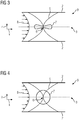
- FIG 3 Another analysis cell (9) is shown, in which there is a red blood cell (7).
- a speed profile (8) of the red blood cells (7) moving in the direction x within the flow cell is shown vectorially depending on the position of the red blood cells in the direction z.
- a piezo element (1) is arranged in the region of the outer side of the channel wall and is operated with a voltage of 23 volts and a frequency of approximately 1 MHz, preferably 1.113 MHz, or with a voltage of 23 volts and a frequency of approximately 5 MHz , preferably operated at 5.397 MHz.
- the temperature of the red blood cells (7) is 36 degrees Celsius and the red blood cells (7) are in their native state and are not spherical.
- the course of the acoustic wave (5) that is generated by the piezo element (1) is shown.
- An acoustic wave node (6) is located in the area of half the channel height (3) and the red blood cell (7).
- the red blood cell (7) is affected by acoustic forces pulled into the area of the acoustic wave node and held there.
- FIG 4 is the same analysis cell (9) as in FIG 3 shown.
- the piezo element (1) is operated with a voltage of 75 volts and a frequency of approximately 1 MHz, preferably 1.113 MHz, or with a voltage of 75 volts and a frequency of approximately 5 MHz, preferably 5.397 MHz.
- the temperature of the red blood cell (7) is 48 degrees Celsius and the red blood cell (7) is completely spherical.
- the course of the acoustic wave (5) that is generated by the piezo element (1) is shown.
- An acoustic wave node (6) is located in the area of half the channel height (3) and the red blood cell (7).
- the red blood cell (7) is pulled by acoustic forces into the area of the acoustic wave node and held there.
Landscapes
- Chemical & Material Sciences (AREA)
- Immunology (AREA)
- Physics & Mathematics (AREA)
- Health & Medical Sciences (AREA)
- Analytical Chemistry (AREA)
- Biochemistry (AREA)
- General Health & Medical Sciences (AREA)
- Life Sciences & Earth Sciences (AREA)
- General Physics & Mathematics (AREA)
- Pathology (AREA)
- Dispersion Chemistry (AREA)
- Investigating Or Analysing Biological Materials (AREA)
- Optical Measuring Cells (AREA)
- Investigating Or Analysing Materials By Optical Means (AREA)
- Apparatus Associated With Microorganisms And Enzymes (AREA)
- Measuring Or Testing Involving Enzymes Or Micro-Organisms (AREA)
- Micro-Organisms Or Cultivation Processes Thereof (AREA)
Abstract
Description
- Die Erfindung liegt auf dem Gebiet der automatischen Analyzer und betrifft einen Hämatologie-Analyzer zum Analysieren von Zellen in einer Probe. Die Zellen werden dabei vor der Analyse mittels piezoelektrischen Heizens erwärmt und isovolumetrisch aufgekugelt.
- Zur automatisierten Analyse von Zellen werden automatisierte Zellzählgeräte (automated cell counters) mit zunehmendem Erfolg angewendet. Beispiele hierfür sind das Advia 2120, Sysmex XE-2100, CellaVision DM96 sowie CellaVision DM1200 Gerät. Diese automatisierten Geräte stellen, abgesehen von ihrer hohen Durchsatzzahl, einige Vorteile bereit, wie beispielsweise hohe Objektivität (keine Variabilität abhängig vom Beobachter), Elimination statistischer Variationen, die üblicherweise mit einer manuellen Zählung verbunden sind (Zählung hoher Zellzahlen), sowie die Bestimmung zahlreicher Parameter, die bei einer manuellen Auszählung nicht verfügbar wären und, wie angesprochen eine effizientere und kosteneffektivere Handhabung. Einige dieser Geräte können 120 bis 150 Patientenproben pro Stunde bearbeiten.
- Die technischen Prinzipien der automatischen Einzelzellzählung beruhen meist entweder auf einer Impedanz- (Widerstands-) Messung oder auf einem optischen System (Streulicht- bzw. Absorptionsmessung). Weiter sind bildgebende Systeme etabliert, die z.B. Zellen eines Blutausstrichs automatisiert abbilden und bewerten.
- Beim Impedanzverfahren erfolgt die Zellzählung sowie deren Größenbestimmung auf Grundlage des Nachweises und der Messung von Veränderungen in der elektrischen Leitfähigkeit (Widerstand), die durch ein Teilchen verursacht werden, das sich durch eine kleine Öffnung hindurchbewegt. Teilchen, wie beispielsweise Blutzellen, sind selbst nicht leitend, werden jedoch in einem elektrisch leitenden Verdünnungsmittel suspendiert. Wenn eine derartige Suspension von Zellen durch eine Öffnung hindurchgeleitet wird, nimmt bei Durchgang einer einzelnen individuellen Zelle die Impedanz (Widerstand) des elektrischen Weges zwischen den beiden Elektroden, die sich auf jeder Seite der Öffnung befinden, vorübergehend zu.
- Im Gegensatz zum Impedanzverfahren umfasst das optische Verfahren das Durchleiten eines Laserlichtstrahles oder eines LED Lichtstrahls durch eine verdünnte Blutprobe, die in einem kontinuierlichen Strom von dem Laserstrahl oder dem LED Lichtstrahl erfasst wird. Der entsprechende Lichtstrahl kann dabei z.B. mittels eines Lichtwellenleiters zur Durchflusszelle geleitet werden. Jede Zelle, die durch die Erfassungszone der Durchflusszelle hindurchtritt, streut das fokussierte Licht. Das gestreute Licht wird dann durch einen Fotodetektor nachgewiesen und in einen elektrischen Impuls umgewandelt. Die hier erzeugte Anzahl von Impulsen ist direkt zur Zellanzahl proportional, die durch die Erfassungszone in einer speziellen Zeitspanne hindurchtritt.
- Bei den optischen Verfahren wird die Lichtstreuung der einzelnen Zelle, die durch die Erfassungszone hindurchtritt, in verschiedenen Winkeln gemessen. Hierdurch wird das Streuverhalten der jeweiligen Zelle für die optische Strahlung erfasst, das Rückschlüsse auf z.B. die Zellstruktur, Form und Reflexionsvermögen erlaubt. Dieses Streuverhalten kann dazu verwendet werden, verschiedene Arten von Blutzellen zu differenzieren und die abgeleiteten Parameter zur Diagnose von Abweichungen der Blutzellen dieser Probe von einer Norm, die z.B. aus einer Vielzahl von als normal klassifizierten Referenzproben gewonnen wurde, zu verwenden.
- Bei der automatisierten Bewertung von Zellen in z.B. Blutausstrichen arbeiten die heutigen Analysatoren mit Mikroskopen mit einer hohen numerischen Apertur und mit Immersion zwischen dem Objektträger und dem Objektiv, um eine hohe Auflösung erreichen zu können. Dadurch ergibt sich jedoch eine vergleichsweise geringe Tiefenschärfe, die deutlich geringer ist als die Dicke der Zellen senkrecht zur Fläche des Objektträgers mit dem Blutausstrich. Entsprechend kann mit einer zweidimensionalen Abbildung in nur einer Fokuseinstellung nicht die gesamte Tiefeninformation der Zelle scharf abgebildet werden. Häufig kommt es daher zu unklar klassifizierten Blutzellen, die Fachpersonal, z.B. ein Laborarzt, manuell nachklassifizieren muss.
- Die momentan gebräuchlichen Messgeräte in der Hämatologie umfassen bezüglich des optischen Systems ein Mikroskop mit etwa 100-facher Vergrößerung mit effektiven lateralen Auflösungen eines Sensorelements auf der Objektebene von 100 nm = 0,1 µm. Die gebräuchlichen Kameras haben Pixelzahlen von max. 0,3 bis 1 Millionen Pixeln. Dadurch ist das Gesichtsfeld im Objekt nur wenige 100 µm groß. Um den gefärbten Ausstrich einer Blutprobe, der einige mm breit und mehrere 10 mm lang sein kann, aufnehmen und analysieren zu können, muss dann die Fläche des zu analysierenden Bereichs des Ausstriches mit einer Verschiebeeinheit in einem Mäanderscanverfahren abgetastet werden. Um den Prozess etwas zu beschleunigen wird ein erster flächenhafter Scan mit geringer Vergrößerung, z.B. 10-fach mit entsprechend 10-fach größerem Gesichtsfeld durchgeführt und nach einer ersten Bildauswertung zum Auffinden der zu vermessenden Zellen werden dann nur die Regions of Interest (RoI) mit den Zellen mit der höheren Vergrößerung anschließend gezielt angefahren. Das bedeutet, dass eine vollständige flächenhafte Analyse der Probe mit der hohen Vergrößerung nicht erfolgt. Um die Zellen hinreichend gut sichtbar zu machen um sie mit der hochauflösenden optischen Mikroskopie analysieren zu können, werden die Blutausstriche in einem vorgelagerten Schritt angefärbt. Es haben sich mehrere Färbeprotokolle weltweit etabliert, die sich global gesehen teilweise von Region zu Region unterscheiden. Somit ist die Vergleichbarkeit der Analyse von Blutausstrichen regional begrenzt, da nur Bilder von Zellen gut miteinander verglichen werden können, die nach demselben Protokoll angefärbt worden sind.
- Für die Analyse von roten Blutzellen (RBC) werden diese insbesondere in Durchflusssystemen aufgerundet, wobei dieser Vorgang wird auch als Aufkugeln bezeichnet wird.
- Das Aufrunden bzw. Aufkugeln von nativen biconkaven roten Blutzellen ermöglicht eine genaue Analyse deren Volumens und weiterer Parameter mit Hilfe geometrischer Formeln, siehe dazu z.B. Y. C. B. Fung und P. Tong "Theory of the sphering of red blood cells", Biophysical Journal, Volume 8 (1968).
- Der Prozess des Aufkugelns soll dabei in der Praxis gut in einen komplexen Probenaufbereitungsprozess, wie er bei einem Hämatologieautomaten typischerweise vorliegt, integrierbar sein, um einen raschen Workflow und gleichzeitig einen hohen Durchsatz von Proben zu erzielen.
- Das isovolumetrische Aufkugeln wird in bekannten Hämatologie-Analysatoren angewendet indem die Probe mit einem hypotonen Puffer versetzt wird, der häufig zusätzlich ein die Zellmembran destabilisierenden Agens wie z.B. Sodiumdodecylsulfat(SDS) enthält. Der Einsatz hypotoner Flüssigkeiten zur Aufkugelung resultiert dabei in einer sehr hohen Verdünnung der Probe um z.B. einen Faktor 630. Weiter führt dieses Vorgehen zur isovolumetrischen Aufkugelung dazu, dass die roten Blutzellen sich in einem Zustand befinden, der sich hochgradig von einem nativen Zustand unterscheidet. Dazu kann auch die Kombination der hypotonen Flüssigkeit und des die Zellmembran destabilisierenden Agens besonders beitragen.
- Die Analyse dieser aufgekugelten Zellen umfasst z.B. eine Bestimmung ihres Volumens oder des Hämoglobins und erfolgt in Hämatologie-Analysatoren z.B. optisch durch Einsatz monochromatischen Lichts, welches durch Laser oder LED erzeugt wird sowie die Anwendung der Mie-Theorie zur Auswertung spherischer Objekte. Alternativ können die aufgekugelten Zellen auch z.B. impedimetrisch durch Messung der Leitfähigkeit in einem definierten Volumen einer Ionen enthaltenden Flüssigkeit analysiert werden (Coulter-Prinzip).
- Es sind auch Methoden bekannt in denen Hitze in Form eines entsprechend temperierten Wasserbads eingesetzt wird, um rote Blutzellen aufzukugeln, siehe dazu z.B. N. Matsumoto, Y. Yawata and H. S. Jocob "Association of Decreased Membrane Protein Phosphorylation With Red Blood Cell Spherocytosis", Blood, Volume 49, No. 2 (February) (1977). Hierbei kann teilweise eine sehr hohe Verdünnung der Probe entfallen. Jedoch kommt es aufgrund der Erwärmung sehr leicht zu weiteren Veränderungen an den roten Blutzellen, wie z.B. einer Agglutination der Proteine in und an den Blutzellen, wodurch sich die Morphologie der roten Blutzellen auf Grund einer Überhitzung sehr stark verändert und eine entsprechende, präzise Analyse der Zellen unmöglich macht.
- Weiter ist es für eine bildgebende Analyse notwendig, die aufgekugelten roten Blutzellen in den optischen Fokus eines Mikroskops zu bringen, um anschließend eine präzise Bildanalyse zu ermöglichen.
- Eine der Erfindung zugrundeliegende Aufgabe ist somit das Bereitstellen eines automatischen Analyzers zum Analysieren einer medizinischen Probe sowie eines Verfahrens zum Aufkugeln einer Zelle einer medizinischen Probe, wobei die Aufkugelung der Zelle ohne eine sehr hohe Verdünnung der Probe erreicht werden kann und gleichzeitig die Zellen in einem möglichst ursprünglichen und wenig oder überhaupt nicht veränderten Zustand, abgesehen von der Aufkugelung, analysiert werden können, also z.B. chemische Vorbehandlungen der Zelle weitest möglichst unterbleiben sollen und idealerweise vollständig auf eine Markierung der Zellen verzichtet werden kann. Weiter sollen auch die Nachteile, die sich bei den bekannten Methoden, die Hitze zur Aufkugelung einsetzten ergeben, vermieden werden. So soll z.B. eine Agglutination der Proteine in und an den Zellen und eine hierdurch hervorgerufene Änderung der Morphologie aufgrund einer Überhitzung vermieden werden. Weiter ist es eine Aufgabe der Erfindung, die entsprechend schonend und markierungsfrei aufgekugelten Zellen in den optischen Fokus eines Mikroskops zu bringen, um anschließend eine präzise Bildanalyse zu ermöglichen.
- Der Gegenstand der Erfindung umfasst insbesondere einen Analyzer zum Analysieren einer medizinischen Probe, der Analyzer umfassend eine Analysezelle für die Probe, ein Piezoelement und eine Analysevorrichtung, wobei das Piezoelement durch Anlegen einer Spannung und einer Frequenz betrieben werden kann und dabei ein akustisches Wellenfeld generiert, wobei eine sich in der Analysezelle befindende Probe bei Betrieb des Piezoelements in dem akustischen Wellenfeld befindet.
- Ein erfindungsgemäßer Analyzer hat den Vorteil, dass auf den bisher notwendigen Einsatz von hypotonen Puffern und ein die Zellmembran destabilisierenden Agens zum aufkugeln der Zellen verzichtet werden kann. Weiter ist eine sehr hohe Verdünnung der Probe nicht länger nötig und es werden gleichzeitig auch die Nachteile, die sich bei einer herkömmlichen Erhitzung mittels eines Wasserbades ergeben, weitestgehend vermieden. Weiter können die aufgekugelten Zellen mittels des erzeugten akustischen Wellenfeldes und der entsprechenden akustischen Kräfte gleichzeitig auch in den optischen Fokus eines Mikroskops gebracht und/oder gehalten werden, um anschließend eine präzise Bildanalyse zu ermöglichen. Weiter kann auf eine Färbung oder sonstige Markierung der Proben für die anschließende Mikroskopie vollständig oder teilweise verzichtet werden. Bevorzugt handelt es sich bei dem erfindungsgemäßen Analysator um einen automatischen Analysator, besonders bevorzugt um einen teilautomatischen oder vollautomatischen Analysator. Weiter handelt es sich bei dem Analyzer bevorzugt um einen Hämatologie-Analyzer, besonders bevorzugt um einen automatischen Hämatologie-Analyzer.
- In einer bevorzugten Ausführungsform des Analyzers wird eine sich in der Analysezelle befindende Probe bei Betrieb des Piezoelements durch das Wellenfeld erwärmt, bevorzugt auf mindestens 48 Grad Celsius, besonders bevorzugt auf mindestens 50 Grad Celsius. Dies hat den Vorteil, dass zuverlässig eine vollständige Aufkugelung von roten Blutzellen erreicht werden kann.
- In einer bevorzugten Ausführungsform des Analyzers wird das Piezoelement durch Anlegen einer Spannung von 35 Volt bis 100 Volt, bevorzugt 40 bis 80 Volt, besonders bevorzugt von 75 Volt und einer Frequenz von etwa 1 MHz, bevorzugt 1,113 MHz, oder einer Frequenz von etwa 5 MHz, bevorzugt 5,397 MHz betrieben. Dies hat den Vorteil, dass eine sich in der Analysezelle befindende Zelle einer medizinischen Probe besonders sicher, schnell und effizient auf eine Temperatur von 48 oder 50 Grad Celsius erwärmt werden kann.
- In einer weiteren bevorzugten Ausführungsform des Analyzers handelt es sich bei der Analysezelle um eine Durchflusszelle, bevorzugt um eine mikrofluidische Durchflusszelle. Dies hat den Vorteil, dass ein optimierter Workflow und ein hoher Durchsatz von Proben erreicht werden kann. Weiter hat dies den Vorteil, dass die Zellen in einer flüssigen Umgebung und damit unter nativeren Bedingungen analysiert werden kann. Bevorzugt bewegt sich die Probe innerhalb der Analysezelle mit einer Durchflussgeschwindigkeit zwischen 0,002 und 5 mm pro Sekunde, besonders bevorzugt zwischen 0,002 und 0,1 mm pro Sekunde bewegt. Dabei sind die Flussbedingungen vorteilhafterweise laminar.
- In einer weiteren bevorzugten Ausführungsform des Analyzers umfasst die Analysevorrichtung ein optisches Mikroskop, bevorzugt ein digitales holographisches Mikroskop (DHM) zur Analyse einer sich in der Analysezelle befindenden Probe. Bevorzugt umfasst das Mikroskop ein 20- bis 60-fach Objektiv. Dies hat den Vorteil, dass die Vergrößerung so angepasst werden kann, dass die aufgekugelten roten Blutzellen mit einer Fokuseinstellung hinreichend scharf abgebildet werden können.
- In einer weiteren bevorzugten Ausführungsform des Analyzers wird eine sich in der Analysezelle befindende Zelle einer medizinischen Probe mittels akustischer Kräfte in den Fokusberiech des Mikroskops gebracht und/oder gehalten, wobei die akustischen Kräfte mittels des Piezoelements erzeugt werden. Bevorzugt beträgt die hierfür angelegte Spannung 8 bis 12 Volt und die Frequenz etwa 1 MHz, bevorzugt 1,113 MHz, oder etwa 5 MHz, bevorzugt 5,397 MHz. Dies hat den Vorteil, dass die Zelle berührungslos in den Fokusbereich gebracht bzw. gehalten werden kann. Gleichzeitig kommt es zu keiner Erwärmung der Zelle und dementsprechend zu keiner thermisch induzierten morphologischen Veränderung der Zelle wie sie bei höheren Spannungen auftritt. Die Zellen werden also nicht Kugelförmig sondern bleiben bikonkav.
- Ein weiterer Gegenstand der Erfindung ist ein Verfahren zum Aufkugeln einer Zelle einer medizinischen Probe mittels Erwärmung, wobei sich die Zelle in einer Analysezelle befindet und wobei mittels eines mit einer Spannung und einer Frequenz betriebenen Piezoelements ein akustisches Wellenfeld generiert wird und wobei sich die Zelle in dem Wellenfeld befindet und durch das Wellenfeld erwärmt und dadurch aufgekugelt wird.
- In einer bevorzugten Ausgestaltung des Verfahrens erfolgt die Aufkugelung isovolumetrisch. Dies hat den Vorteil, dass das Zellvolumen z.B. der roten Blutzelle, durch die Aufkugelung unverändert erhalten bleibt. Dies kann für eine entsprechende quantitative, präzise Analyse des Zellvolumens von hoher Bedeutung sein.
- In einer weiteren bevorzugten Ausgestaltung des Verfahrens wird die Zelle auf mindestens 48 Grad Celsius, besonders bevorzugt auf mindestens 50 Grad Celsius erwärmt wird. Dies hat den Vorteil, dass zuverlässig eine vollständige Aufkugelung von roten Blutzellen erreicht werden kann.
- In einer weiteren bevorzugten Ausgestaltung des Verfahrens bewegt sich die Zelle in der Analysezelle mit einer Durchflussgeschwindigkeit zwischen 0,002 und 5 mm pro Sekunde, besonders bevorzugt zwischen 0,002 und 0,01 mm pro Sekunde.
- In einer weiteren bevorzugten Ausgestaltung des Verfahrens wird die Zelle nach der Aufkugelung mittels einer Analysevorrichtung, die ein optisches Mikroskop, bevorzugt ein digitales holographisches Mikroskop (DHM) umfasst, analysiert und/oder abgebildet, wobei sich die Zelle während der Analyse und/oder Abbildung bevorzugt in einem Fokusbereich des Mikroskops befindet. Dies hat den Vorteil, dass eine Abbildung der Zelle in hoher Qualität erfolgen kann und somit eine präzise, quantitative Analyse z.B. des Zellvolumens oder anderer Zellparameter erfolgen kann.
- In einer weiteren bevorzugten Ausgestaltung des Verfahrens wird die Zelle in den Fokusberiech des Mikroskops durch akustische Kräfte gebracht und/oder gehalten, wobei dies bevorzugt zeitgleich mit der Aufkugelung der Zelle erfolgt.
- In einer weiteren bevorzugten Ausgestaltung des Verfahrens wird die Zelle in den Fokusberiech des Mikroskops durch einen gleichzeitigen Einsatz von akustischen und mikrofluidischen Kräften gebracht und/oder gehalten, wobei dies bevorzugt zeitgleich mit der Aufkugelung der Zelle erfolgt.
- Bevorzugt werden die akustischen Kräfte um die Zelle in den Fokusberiech des Mikroskops zu bringen und/oder zu halten mittels des Piezoelements erzeugt. Bevorzugt beträgt die hierfür angelegte Spannung 8 bis 12 Volt und die Frequenz etwa 1 MHz, bevorzugt 1,113 MHz, oder etwa 5 MHz, bevorzugt 5,397 MHz.
- In einer weiteren bevorzugten Ausgestaltung des Verfahrens erfolgt die Aufkugelung der Zelle innerhalb einer Durchflusszelle in einem ersten Bereich der Durchflusszelle, bevorzugt mittels einer angelegten Frequenz von 1 MHz, besonders bevorzugt 1,113 MHz an das Piezoelement. Bevorzugt befindet sich der erste Bereich der Durchflusszelle stromaufwärts des Fokusbereichs des Mikroskops. Der Fokusberiech des Mikroskops befindet sich in einem zweiten Bereich der Durchflusszelle, wobei der erste Bereich bevorzugt stromaufwärts des zweiten Bereichs angeordnet ist. Bevorzugt erfolgt die Anhebung der Zelle in den Fokusbereich des Mikroskops dann flussabwärts im zweiten Bereich der Durchflusszelle, bevorzugt mittels einer angelegten Frequenz von 5 MHz, besonders bevorzugt 5,397 MHz an das Piezoelement. Dies hat den Vorteil, dass eine Aufkugelung der Zelle ohne weitere unerwünschte thermisch induzierte weitere Veränderungen an der Zelle auch dann möglich ist, wenn eine zeitgleiche Aufkugelung und Fokussierung solche unerwünschten Veränderungen nach sich ziehen würde und/oder solche Veränderungen nicht ausgeschlossen werden könnten.
- In einer weiteren bevorzugten Ausgestaltung des Verfahrens wird die Zelle unmittelbar nach der Aufkugelung, bevorzugt innerhalb von 0,05 bis 1 Sekunde nach der Aufkugelung analysiert und/oder abgebildet. Dies hat den Vorteil, dass möglicherweise auftretende, unerwünschte Veränderungen der Zelle aufgrund der Erwärmung oder einer Überhitzung der Zelle erst zu einem Zeitpunkt eintreten, bei denen die Analyse und/oder die Abbildung der Zelle bereits abgeschlossen sind.
- In einer weiteren bevorzugten Ausgestaltung des Verfahrens handelt es sich bei der Zelle um eine menschliche oder tierische Zellen, bevorzugt eine Blutzelle, besonders bevorzugt eine rote Blutzelle.
- In einer weiteren bevorzugten Ausgestaltung des Verfahrens ist die Zelle eine rote Blutzelle und wobei die Analyse der Zelle eine Volumenbestimmung und/oder eine Bestimmung von Einzelzell-Hämoglobin (MCH) und/oder eine Detektion von Malaria Parasiten umfasst.
- Ein weiterer Gegenstand der Erfindung ist eine Verwendung eines erfindungsgemäßen Verfahrens in einem automatischen Analyzer, bevorzugt in einem erfindungsgemäßen automatischen Analyzer.
- Bevorzugt umfasst die medizinische Probe eine Zelle und/oder ein medizinisches Präparat. Bevorzugt handelt es sich bei dem medizinischen Präparat um einen Gewebeschnitt, Sedimente aus Körpersekreten und/oder Körperflüssigkeiten und/oder Mikrokristalle. Dies hat den Vorteil, dass verschiedenste Probentypen, einschließlich verschiedenster Zelltypten, untersucht und charakterisiert werden können.
-
- FIG 1
- eine Analysezelle (9), in der sich rote Blutzellen (7) befinden ohne akustophoretisches Heizen, wobei ein Piezoelement (1) mit 23 Volt betrieben wird,
- FIG 2
- eine Analysezelle (9), in der sich aufgekugelte rote Blutzellen (7) befinden mit akustophoretischem Heizen, wobei ein Piezoelement (1) mit 75 Volt betrieben wird,
- FIG 3
- eine Analysezelle (9), in der sich rote Blutzellen (7) befinden, wobei ein Piezoelement (1) mit 23 Volt betrieben wird,
- FIG 4
- eine Analysezelle (9), in der sich aufgekugelte rote Blutzellen (7) befinden, wobei ein Piezoelement (1) mit 75 Volt betrieben wird.
- Die in
FIG 1 gezeigte Analysezelle (9) umfasst Kanalwände (2) und ein Piezoelement (1) und ist Teil eines automatischen Analyzers zum Analysieren von Zellen in einer Probe. Der Analyzer umfasst eine Analysevorrichtung (10), die als optisches Mikroskop ausgestaltet ist und eine Lichtquelle zum Beleuchten einer Probe in der Analysezelle (9) und eine Sammellinse zum Sammeln und Fokussieren von Lichtstrahlen umfasst, die von der beleuchteten Probe ausgehen. Bei der Probe handelt es sich um eine Blutprobe, die rote Blutzellen (7) enthält. Die Probe befindet sich in der Analysezelle (9), die als mikrofluidische Durchflusszelle ausgestaltet ist. Weiter umfasst das Mikroskop eine Kamera umfassend ein digitales Aufzeichnungsgerät, das Aufzeichnungsgerät umfassend einen CCD Chip oder einen CMOS Chip, zum Aufnehmen des im Mikroskop abgebildeten Lichtfelds. Die Analysezelle (9) und das Mikroskop sind so ausgestaltet, dass rote Blutzellen (7), die sich in einem optischen Fenster (4) befinden, abgebildet und analysiert werden können. Das Piezoelement (1) ist im äußeren Bereich an der Kanalwand (2) unmittelbar vor dem optischen Fenster (4) in Flussrichtung x der roten Blutzellen (7) angeordnet. Ein Geschwindigkeitsprofil (8) der roten Blutzellen (7), die sich in Richtung x bewegen innerhalb der Durchflusszelle ist vektoriell dargestellt in Abhängigkeit der Position der roten Blutzellen in Richtung y. - Das Piezoelement (1) wird mit einer Spannung von 25 Volt und einer Frequenz von etwa 1 MHz, bevorzugt 1,113 MHz, oder mit einer Spannung von 25 Volt und einer Frequenz von etwa 5 MHz, bevorzugt 5,397 MHz betrieben Die Temperatur der roten Blutzellen (7) beträgt weniger als 48 Grad Celsius und die roten Blutzellen (7) befinden sich in ihrem nativen Zustand und sind nicht aufgekugelt.
- In
FIG 2 ist die gleiche Analysezelle (9) wie inFIG 1 gezeigt. Nun wird das Piezoelement (1) mit einer Spannung von 75 Volt und einer Frequenz von etwa 1 MHz, bevorzugt 1,113 MHz, oder mit einer Spannung von 75 Volt und einer Frequenz von etwa 5 MHz, bevorzugen 5,397 MHz betrieben. Die Temperatur der roten Blutzellen (7) beträgt mindestens 48 Grad Celsius und die roten Blutzellen (7) sind aufgekugelt. - In
FIG 3 ist eine weitere Analysezelle (9) gezeigt, in der sich eine rote Blutzelle (7) befindet. Ein Geschwindigkeitsprofil (8) der roten Blutzellen (7), die sich in Richtung x bewegen innerhalb der Durchflusszelle ist vektoriell dargestellt in Abhängigkeit der Position der roten Blutzellen in Richtung z. Ein nicht gezeigtes Piezoelement (1) ist im Bereich der äußeren Seite der Kanalwand angeordnet und wird mit einer Spannung von 23 Volt und einer Frequenz von etwa 1 MHz, bevorzugt 1,113 MHz, oder mit einer Spannung von 23 Volt und einer Frequenz von etwa 5 MHz, bevorzugt 5,397 MHz betrieben. Die Temperatur der roten Blutzellen (7) beträgt 36 Grad Celsius und die rote Blutzelle (7) befinden sich in ihrem nativen Zustand und ist nicht aufgekugelt. Gezeigt ist der Verlauf der akustischen Welle (5), die durch das Piezoelement (1) erzeugt wird. Ein akustischer Wellenknoten (6) befindet sich im Bereich der halben Kanalhöhe (3) und der roten Blutzelle (7). Die rote Blutzelle (7) wird durch akustische Kräfte in den Bereich des akustischen Wellenknotens gezogen und dort gehalten. - In
FIG 4 ist die gleiche Analysezelle (9) wie inFIG 3 gezeigt. Das Piezoelement (1) wird mit einer Spannung von 75 Volt und einer Frequenz von etwa 1 MHz, bevorzugt 1,113 MHz, oder mit einer Spannung von 75 Volt und einer Frequenz von etwa 5 MHz, bevorzugt 5,397 MHz betrieben. Die Temperatur der roten Blutzelle (7) beträgt 48 Grad Celsius und die rote Blutzelle (7) ist vollständig aufgekugelt. Gezeigt ist der Verlauf der akustischen Welle (5), die durch das Piezoelement (1) erzeugt wird. Ein akustischer Wellenknoten (6) befindet sich im Bereich der halben Kanalhöhe (3) und der roten Blutzelle (7). Die rote Blutzelle (7) wird durch akustische Kräfte in den Bereich des akustischen Wellenknotens gezogen und dort gehalten. -
- 1
- Piezoelement
- 2
- Kanalwand
- 3
- Halbe Kanalbreite
- 4
- Optisches Fenster
- 5
- Akustische Welle
- 6
- Akustischer Wellenknoten
- 7
- Rote Blutzelle (RBC)
- 8
- Geschwindigkeitsprofil
- 9
- Analysezelle
Claims (18)
- Automatischer Analyzer zum Analysieren einer medizinischen Probe, der Analyzer umfassend eine Analysezelle für die Probe, ein Piezoelement und eine Analysevorrichtung, wobei das Piezoelement durch Anlegen einer Spannung und einer Frequenz betrieben werden kann und dabei ein akustisches Wellenfeld generiert, dadurch gekennzeichnet, dass eine sich in der Analysezelle befindende Probe bei Betrieb des Piezoelements in dem akustischen Wellenfeld befindet.
- Automatischer Analyzer nach Anspruch 1, wobei eine sich in der Analysezelle befindenden Probe bei Betrieb des Piezoelements durch das Wellenfeld erwärmt wird, bevorzugt auf mindestens 48 Grad Celsius, besonders bevorzugt auf mindestens 50 Grad Celsius.
- Automatischer Analyzer nach einem der vorhergehenden Ansprüche, wobei es sich bei der Analysezelle um eine Durchflusszelle, bevorzugt um eine mikrofluidische Durchflusszelle handelt.
- Automatischer Analyzer nach Anspruch 3, wobei die Probe sich innerhalb der Analysezelle mit einer Durchflussgeschwindigkeit zwischen 0,002 und 5 mm pro Sekunde, besonders bevorzugt zwischen 0,002 und 0,1 mm pro Sekunde bewegt.
- Automatischer Analyzer nach einem der vorhergehenden Ansprüche, wobei die Analysevorrichtung ein optisches Mikroskop, bevorzugt ein digitales holographisches Mikroskop (DHM) zur Analyse einer sich in der Analysezelle befindenden Probe umfasst.
- Automatischer Analyzer nach Anspruch 5, wobei das Mikroskop ein 20- bis 60-fach Objektiv umfasst.
- Automatischer Analyzer nach einem der vorhergehenden Ansprüche, wobei sich eine Probe in der Analysezelle befindet und wobei die Probe menschliche oder tierische Zellen, bevorzugt Blutzellen, besonders bevorzugt rote Blutzellen umfasst.
- Verfahren zum Aufkugeln einer Zelle einer medizinischen Probe mittels Erwärmung, wobei sich die Zelle in einer Analysezelle befindet und wobei mittels eines mit einer Spannung und einer Frequenz betriebenen Piezoelements ein akustisches Wellenfeld generiert wird und wobei sich die Zelle in dem Wellenfeld befindet und durch das Wellenfeld erwärmt und dadurch aufgekugelt wird.
- Verfahren nach Anspruch 8, wobei die Aufkugelung isovolumetrisch erfolgt.
- Verfahren nach einem der Ansprüche 8 oder 9, wobei die Zelle auf mindestens 48 Grad Celsius, besonders bevorzugt auf mindestens 50 Grad Celsius erwärmt wird.
- Verfahren nach einem der Ansprüche 8 bis 10,
wobei es sich bei der Analysezelle um eine Durchflusszelle, bevorzugt um eine mikrofluidische Durchflusszelle handelt. - Verfahren nach einem der Ansprüche 8 bis 11,
wobei sich die Zelle in der Analysezelle mit einer Durchflussgeschwindigkeit zwischen 0,002 und 5 mm pro Sekunde, besonders bevorzugt zwischen 0,002 und 0,1 mm pro Sekunde bewegt. - Verfahren nach einem der Ansprüche 8 bis 12, wobei die Zelle nach der Aufkugelung mittels einer Analysevorrichtung, die ein optisches Mikroskop, bevorzugt ein digitales holographisches Mikroskop (DHM) umfasst, analysiert und/oder abgebildet wird, wobei sich die Zelle während der Analyse und/oder Abbildung bevorzugt in einem Fokusbereich des Mikroskops befindet.
- Verfahren nach Anspruch 13, wobei die Zelle in den Fokusberiech des Mikroskops durch einen gleichzeitigen Einsatz von akustischen und mikrofluidischen Kräften gebracht und/oder gehalten wird, wobei dies bevorzugt zeitgleich mit der Aufkugelung der Zelle erfolgt.
- Verfahren nach einem der Ansprüche 13 oder 14, wobei die Zelle unmittelbar nach der Aufkugelung, bevorzugt innerhalb von 0,05 bis 1 Sekunde nach der Aufkugelung analysiert und/oder abgebildet wird.
- Verfahren nach einem der Ansprüche 8 bis 15, wobei die Zelle eine menschliche oder Tiereiche Zellen ist, bevorzugt eine Blutzelle, besonders bevorzugt eine rote Blutzelle.
- Verfahren nach einem der Ansprüche 13 bis 15, wobei die Zelle eine rote Blutzelle ist und wobei die Analyse der Zelle eine Volumenbestimmung und/oder eine Bestimmung von Einzelzell-Hämoglobin (MCH) und/oder eine Detektion von Malaria Parasiten umfasst.
- Verwendung eines Verfahrens nach einem der Ansprüche 8 bis 17 in einem automatischen Analyzer, bevorzugt in einem automatischen Analyzer nach einem der Ansprüchen 1 bis 7.
Priority Applications (5)
| Application Number | Priority Date | Filing Date | Title |
|---|---|---|---|
| EP18203264.9A EP3647767B1 (de) | 2018-10-30 | 2018-10-30 | Isovolumetrisches aufkugeln von roten blutzellen |
| CN201980071476.5A CN112930473B (zh) | 2018-10-30 | 2019-10-15 | 红细胞的等容球化 |
| US17/289,722 US20220003653A1 (en) | 2018-10-30 | 2019-10-15 | Isovolumetric sphering of red blood cells |
| JP2021547888A JP7465884B2 (ja) | 2018-10-30 | 2019-10-15 | 赤血球の等体積球状化 |
| PCT/EP2019/077849 WO2020088927A1 (de) | 2018-10-30 | 2019-10-15 | Isovolumetrisches aufkugeln von roten blutzellen |
Applications Claiming Priority (1)
| Application Number | Priority Date | Filing Date | Title |
|---|---|---|---|
| EP18203264.9A EP3647767B1 (de) | 2018-10-30 | 2018-10-30 | Isovolumetrisches aufkugeln von roten blutzellen |
Publications (3)
| Publication Number | Publication Date |
|---|---|
| EP3647767A1 true EP3647767A1 (de) | 2020-05-06 |
| EP3647767B1 EP3647767B1 (de) | 2024-09-25 |
| EP3647767C0 EP3647767C0 (de) | 2024-09-25 |
Family
ID=64048715
Family Applications (1)
| Application Number | Title | Priority Date | Filing Date |
|---|---|---|---|
| EP18203264.9A Active EP3647767B1 (de) | 2018-10-30 | 2018-10-30 | Isovolumetrisches aufkugeln von roten blutzellen |
Country Status (5)
| Country | Link |
|---|---|
| US (1) | US20220003653A1 (de) |
| EP (1) | EP3647767B1 (de) |
| JP (1) | JP7465884B2 (de) |
| CN (1) | CN112930473B (de) |
| WO (1) | WO2020088927A1 (de) |
Citations (3)
| Publication number | Priority date | Publication date | Assignee | Title |
|---|---|---|---|---|
| WO2008009311A1 (en) * | 2006-07-17 | 2008-01-24 | Agilent Technologies, Inc. | Temperature adjustment of a fluidic sample within a fluidic device |
| US20130171685A1 (en) * | 2010-06-09 | 2013-07-04 | Celltool Gmbh | Method and apparatus for characterizing biological objects |
| WO2018022158A1 (en) * | 2016-07-28 | 2018-02-01 | The Charles Stark Draper Laboratory, Inc. | Acoustic separation for bioprocessing |
Family Cites Families (18)
| Publication number | Priority date | Publication date | Assignee | Title |
|---|---|---|---|---|
| GB9828765D0 (en) * | 1998-12-29 | 1999-02-17 | Shine Thomas A | A method of testing a cell sample |
| JP2000199744A (ja) | 1999-01-06 | 2000-07-18 | Hitachi Ltd | 分析装置および分析方法 |
| US7641856B2 (en) * | 2004-05-14 | 2010-01-05 | Honeywell International Inc. | Portable sample analyzer with removable cartridge |
| US8980568B2 (en) * | 2001-10-11 | 2015-03-17 | Aviva Biosciences Corporation | Methods and compositions for detecting non-hematopoietic cells from a blood sample |
| US20140008210A1 (en) * | 2012-07-06 | 2014-01-09 | Aviva Biosciences Corporation | Methods and compositions for separating or enriching cells |
| FR2883972B1 (fr) * | 2005-03-31 | 2007-11-16 | C2 Diagnostics Sa | Procede pour l'analyse d'un echantillon de sang et appareil et reactif pour sa mise en oeuvre |
| GB0514349D0 (en) * | 2005-07-13 | 2005-08-17 | Smiths Group Plc | Apparatus and components |
| EP2796208A1 (de) * | 2013-04-22 | 2014-10-29 | Ipratech SA | Verfahren zur Steuerung einer akustischen Zelle |
| DE102014205535A1 (de) * | 2014-03-25 | 2015-10-01 | Siemens Aktiengesellschaft | Vorrichtung und in-vitro Verfahren zur markierungsfreien Darstellung und Analyse von Zellen und Kristallen in einer biologischen Probe |
| EP3174976B1 (de) * | 2014-08-01 | 2020-10-28 | GPB Scientific, Inc. | Verfahren und systeme zur verarbeitung von partikeln |
| WO2018009920A1 (en) | 2016-07-08 | 2018-01-11 | Medica Corporation | Automated microscopic cell analysis |
| CN107533056A (zh) | 2015-02-16 | 2018-01-02 | 弗洛设计声能学公司 | 声学微反应器及其使用方法 |
| US10161926B2 (en) | 2015-06-11 | 2018-12-25 | Flodesign Sonics, Inc. | Acoustic methods for separation of cells and pathogens |
| US10648900B2 (en) * | 2015-12-23 | 2020-05-12 | Becton, Dickinson And Company | Multi-color flow cytometric analysis of samples with low cell numbers |
| EP3362777B1 (de) * | 2015-12-23 | 2023-02-22 | Siemens Healthcare GmbH | Fliesszelle zur analyse von partikeln in einer zu untersuchenden flüssigkeit, verfahren und verwendung |
| FR3049062B1 (fr) * | 2016-03-17 | 2023-06-02 | Commissariat Energie Atomique | Procede de caracterisation d’un echantillon liquide comportant des particules |
| US10656070B2 (en) * | 2016-03-30 | 2020-05-19 | Siemens Healthcare Gmbh | Aligning a non-spherical biological entity in a sample flow using ambient viscoelastic fluid flows |
| SG11201811220UA (en) * | 2016-07-01 | 2019-01-30 | Life Technologies Corp | Methods, systems and devices for concentration of particles |
-
2018
- 2018-10-30 EP EP18203264.9A patent/EP3647767B1/de active Active
-
2019
- 2019-10-15 US US17/289,722 patent/US20220003653A1/en not_active Abandoned
- 2019-10-15 JP JP2021547888A patent/JP7465884B2/ja active Active
- 2019-10-15 WO PCT/EP2019/077849 patent/WO2020088927A1/de not_active Ceased
- 2019-10-15 CN CN201980071476.5A patent/CN112930473B/zh active Active
Patent Citations (3)
| Publication number | Priority date | Publication date | Assignee | Title |
|---|---|---|---|---|
| WO2008009311A1 (en) * | 2006-07-17 | 2008-01-24 | Agilent Technologies, Inc. | Temperature adjustment of a fluidic sample within a fluidic device |
| US20130171685A1 (en) * | 2010-06-09 | 2013-07-04 | Celltool Gmbh | Method and apparatus for characterizing biological objects |
| WO2018022158A1 (en) * | 2016-07-28 | 2018-02-01 | The Charles Stark Draper Laboratory, Inc. | Acoustic separation for bioprocessing |
Non-Patent Citations (5)
| Title |
|---|
| GIOVANNA TOMAIUOLO: "Biomechanical properties of red blood cells in health and disease towards microfluidics", BIOMICROFLUIDICS., 3 September 2014 (2014-09-03), XP055579789, Retrieved from the Internet <URL:https://www.ncbi.nlm.nih.gov/pmc/articles/PMC4189537/> [retrieved on 20190410], DOI: 10.1063/1.4895755 * |
| HEMANTH JAGANNATHAN ET AL: "Ultrasonic temperature control and measurement in microfluidic channels", PROCEEDINGS OF SPIE MEDICAL IMAGING 1997, vol. 4982, 25 January 2003 (2003-01-25), 1000 20th St. Bellingham WA 98225-6705 USA, pages 243 - 247, XP055579871, ISSN: 0277-786X, ISBN: 978-1-5106-2781-9, DOI: 10.1117/12.478162 * |
| N MATSUMOTO ET AL: "Association of decreased membrane protein phosphorylation with red blood cell spherocytosis", BLOOD, 1 February 1977 (1977-02-01), United States, pages 233, XP055579903, Retrieved from the Internet <URL:http://www.bloodjournal.org/content/bloodjournal/49/2/233.full.pdf> [retrieved on 20190411] * |
| N. MATSUMOTO; Y. YAWATA; H. S. JOCOB: "Association of Decreased Membrane Protein Phosphorylation With Red Blood Cell Spherocytosis", BLOOD, vol. 49, no. 2, February 1977 (1977-02-01) |
| Y. C. B. FUNG; P. TONG: "Theory of the sphering of red blood cells", BIOPHYSICAL JOURNAL, vol. 8, 1968 |
Also Published As
| Publication number | Publication date |
|---|---|
| WO2020088927A1 (de) | 2020-05-07 |
| EP3647767B1 (de) | 2024-09-25 |
| EP3647767C0 (de) | 2024-09-25 |
| JP2022509382A (ja) | 2022-01-20 |
| US20220003653A1 (en) | 2022-01-06 |
| CN112930473B (zh) | 2024-10-29 |
| CN112930473A (zh) | 2021-06-08 |
| JP7465884B2 (ja) | 2024-04-11 |
Similar Documents
| Publication | Publication Date | Title |
|---|---|---|
| DE3705876C2 (de) | Verfahren und Vorrichtung für Fließcytometrie | |
| DE3146423C2 (de) | ||
| DE69115876T2 (de) | Bildgebender Durchflusszytometer | |
| DE102010023099B3 (de) | Verfahren und Vorrichtung zum Charakterisieren von biologischen Objekten | |
| DE69629292T2 (de) | Verfahren zum feststellen der preparationsgüte von objektträgern und proben | |
| EP1248947B1 (de) | Verfahren und vorrichtung zur charakterisierung einer kulturflüssigkeit | |
| DE69007118T2 (de) | Verfahren und gerät zum zählen von teilchen. | |
| DE69409567T2 (de) | Durchflusszellenvorrichtung | |
| DE69214770T2 (de) | Bildgebender Durchflusszytometer | |
| DE60319816T2 (de) | Verfahren zum automatischen erkennen von zellen mit krankheitsbezogener molekularmarkierungs-kompartimentierung | |
| DE2823490A1 (de) | Verfahren zur analyse von organismus- zellen | |
| DE1498824A1 (de) | Vorrichtung zur maschinellen Krebsdiagnose | |
| DE69904228T2 (de) | Ein system für regulation der handhabung von dem milch während des melkprozes und eine methode für regulation von diesem prozess | |
| WO2004070362A1 (de) | Mehrparametriges zell-identifikations- und sortierverfahren und zugehörige vorrichtung | |
| EP3575848A1 (de) | Analyzer zur dreidimensionalen analyse einer medizinischen probe mittels einer lichtfeldkamera | |
| WO2015136038A2 (de) | Gemeinsamer strahlungspfad zum ermitteln von partikelinformation durch direktbildauswertung und durch differenzbildanalyse | |
| DE2551026C3 (de) | Verfahren zur Analysieren von Teilchen | |
| EP3430565B1 (de) | Verfahren zur untersuchung verteilter objekte unter segmentierung eines übersichtbildes | |
| DE102014205535A1 (de) | Vorrichtung und in-vitro Verfahren zur markierungsfreien Darstellung und Analyse von Zellen und Kristallen in einer biologischen Probe | |
| DE3315195A1 (de) | Verfahren zum ausrichten von teilchen in einer fluidprobe | |
| DE112007001907T5 (de) | Verfahren für die Zellanalyse | |
| DE102011055426B4 (de) | Mikroskopieverfahren zur Erkennung biologischer Zielobjekte | |
| DE69221669T2 (de) | Gerät zur Messung von Zellen im Urin | |
| EP3647767B1 (de) | Isovolumetrisches aufkugeln von roten blutzellen | |
| EP3574303B1 (de) | Verfahren und vorrichtung zur untersuchung von zellen |
Legal Events
| Date | Code | Title | Description |
|---|---|---|---|
| PUAI | Public reference made under article 153(3) epc to a published international application that has entered the european phase |
Free format text: ORIGINAL CODE: 0009012 |
|
| STAA | Information on the status of an ep patent application or granted ep patent |
Free format text: STATUS: THE APPLICATION HAS BEEN PUBLISHED |
|
| AK | Designated contracting states |
Kind code of ref document: A1 Designated state(s): AL AT BE BG CH CY CZ DE DK EE ES FI FR GB GR HR HU IE IS IT LI LT LU LV MC MK MT NL NO PL PT RO RS SE SI SK SM TR |
|
| AX | Request for extension of the european patent |
Extension state: BA ME |
|
| STAA | Information on the status of an ep patent application or granted ep patent |
Free format text: STATUS: REQUEST FOR EXAMINATION WAS MADE |
|
| 17P | Request for examination filed |
Effective date: 20201103 |
|
| RBV | Designated contracting states (corrected) |
Designated state(s): AL AT BE BG CH CY CZ DE DK EE ES FI FR GB GR HR HU IE IS IT LI LT LU LV MC MK MT NL NO PL PT RO RS SE SI SK SM TR |
|
| STAA | Information on the status of an ep patent application or granted ep patent |
Free format text: STATUS: EXAMINATION IS IN PROGRESS |
|
| 17Q | First examination report despatched |
Effective date: 20220513 |
|
| RAP1 | Party data changed (applicant data changed or rights of an application transferred) |
Owner name: SIEMENS HEALTHINEERS AG |
|
| GRAP | Despatch of communication of intention to grant a patent |
Free format text: ORIGINAL CODE: EPIDOSNIGR1 |
|
| STAA | Information on the status of an ep patent application or granted ep patent |
Free format text: STATUS: GRANT OF PATENT IS INTENDED |
|
| GRAS | Grant fee paid |
Free format text: ORIGINAL CODE: EPIDOSNIGR3 |
|
| INTG | Intention to grant announced |
Effective date: 20240717 |
|
| GRAA | (expected) grant |
Free format text: ORIGINAL CODE: 0009210 |
|
| STAA | Information on the status of an ep patent application or granted ep patent |
Free format text: STATUS: THE PATENT HAS BEEN GRANTED |
|
| AK | Designated contracting states |
Kind code of ref document: B1 Designated state(s): AL AT BE BG CH CY CZ DE DK EE ES FI FR GB GR HR HU IE IS IT LI LT LU LV MC MK MT NL NO PL PT RO RS SE SI SK SM TR |
|
| REG | Reference to a national code |
Ref country code: GB Ref legal event code: FG4D Free format text: NOT ENGLISH |
|
| REG | Reference to a national code |
Ref country code: CH Ref legal event code: EP |
|
| REG | Reference to a national code |
Ref country code: DE Ref legal event code: R096 Ref document number: 502018015165 Country of ref document: DE |
|
| REG | Reference to a national code |
Ref country code: IE Ref legal event code: FG4D Free format text: LANGUAGE OF EP DOCUMENT: GERMAN |
|
| U01 | Request for unitary effect filed |
Effective date: 20240930 |
|
| U07 | Unitary effect registered |
Designated state(s): AT BE BG DE DK EE FI FR IT LT LU LV MT NL PT RO SE SI Effective date: 20241024 |
|
| U20 | Renewal fee for the european patent with unitary effect paid |
Year of fee payment: 7 Effective date: 20241024 |
|
| PG25 | Lapsed in a contracting state [announced via postgrant information from national office to epo] |
Ref country code: NO Free format text: LAPSE BECAUSE OF FAILURE TO SUBMIT A TRANSLATION OF THE DESCRIPTION OR TO PAY THE FEE WITHIN THE PRESCRIBED TIME-LIMIT Effective date: 20241225 |
|
| PG25 | Lapsed in a contracting state [announced via postgrant information from national office to epo] |
Ref country code: GR Free format text: LAPSE BECAUSE OF FAILURE TO SUBMIT A TRANSLATION OF THE DESCRIPTION OR TO PAY THE FEE WITHIN THE PRESCRIBED TIME-LIMIT Effective date: 20241226 |
|
| PG25 | Lapsed in a contracting state [announced via postgrant information from national office to epo] |
Ref country code: RS Free format text: LAPSE BECAUSE OF FAILURE TO SUBMIT A TRANSLATION OF THE DESCRIPTION OR TO PAY THE FEE WITHIN THE PRESCRIBED TIME-LIMIT Effective date: 20241225 |
|
| PG25 | Lapsed in a contracting state [announced via postgrant information from national office to epo] |
Ref country code: RS Free format text: LAPSE BECAUSE OF FAILURE TO SUBMIT A TRANSLATION OF THE DESCRIPTION OR TO PAY THE FEE WITHIN THE PRESCRIBED TIME-LIMIT Effective date: 20241225 Ref country code: NO Free format text: LAPSE BECAUSE OF FAILURE TO SUBMIT A TRANSLATION OF THE DESCRIPTION OR TO PAY THE FEE WITHIN THE PRESCRIBED TIME-LIMIT Effective date: 20241225 Ref country code: GR Free format text: LAPSE BECAUSE OF FAILURE TO SUBMIT A TRANSLATION OF THE DESCRIPTION OR TO PAY THE FEE WITHIN THE PRESCRIBED TIME-LIMIT Effective date: 20241226 |
|
| PG25 | Lapsed in a contracting state [announced via postgrant information from national office to epo] |
Ref country code: IS Free format text: LAPSE BECAUSE OF FAILURE TO SUBMIT A TRANSLATION OF THE DESCRIPTION OR TO PAY THE FEE WITHIN THE PRESCRIBED TIME-LIMIT Effective date: 20250125 |
|
| PG25 | Lapsed in a contracting state [announced via postgrant information from national office to epo] |
Ref country code: SM Free format text: LAPSE BECAUSE OF FAILURE TO SUBMIT A TRANSLATION OF THE DESCRIPTION OR TO PAY THE FEE WITHIN THE PRESCRIBED TIME-LIMIT Effective date: 20240925 |
|
| PG25 | Lapsed in a contracting state [announced via postgrant information from national office to epo] |
Ref country code: ES Free format text: LAPSE BECAUSE OF FAILURE TO SUBMIT A TRANSLATION OF THE DESCRIPTION OR TO PAY THE FEE WITHIN THE PRESCRIBED TIME-LIMIT Effective date: 20240925 |
|
| PG25 | Lapsed in a contracting state [announced via postgrant information from national office to epo] |
Ref country code: CZ Free format text: LAPSE BECAUSE OF FAILURE TO SUBMIT A TRANSLATION OF THE DESCRIPTION OR TO PAY THE FEE WITHIN THE PRESCRIBED TIME-LIMIT Effective date: 20240925 Ref country code: PL Free format text: LAPSE BECAUSE OF FAILURE TO SUBMIT A TRANSLATION OF THE DESCRIPTION OR TO PAY THE FEE WITHIN THE PRESCRIBED TIME-LIMIT Effective date: 20240925 |
|
| PG25 | Lapsed in a contracting state [announced via postgrant information from national office to epo] |
Ref country code: SK Free format text: LAPSE BECAUSE OF FAILURE TO SUBMIT A TRANSLATION OF THE DESCRIPTION OR TO PAY THE FEE WITHIN THE PRESCRIBED TIME-LIMIT Effective date: 20240925 |
|
| REG | Reference to a national code |
Ref country code: CH Ref legal event code: PL |
|
| PG25 | Lapsed in a contracting state [announced via postgrant information from national office to epo] |
Ref country code: MC Free format text: LAPSE BECAUSE OF FAILURE TO SUBMIT A TRANSLATION OF THE DESCRIPTION OR TO PAY THE FEE WITHIN THE PRESCRIBED TIME-LIMIT Effective date: 20240925 |
|
| PG25 | Lapsed in a contracting state [announced via postgrant information from national office to epo] |
Ref country code: CH Free format text: LAPSE BECAUSE OF NON-PAYMENT OF DUE FEES Effective date: 20241031 |
|
| PLBE | No opposition filed within time limit |
Free format text: ORIGINAL CODE: 0009261 |
|
| STAA | Information on the status of an ep patent application or granted ep patent |
Free format text: STATUS: NO OPPOSITION FILED WITHIN TIME LIMIT |
|
| 26N | No opposition filed |
Effective date: 20250626 |
|
| PG25 | Lapsed in a contracting state [announced via postgrant information from national office to epo] |
Ref country code: IE Free format text: LAPSE BECAUSE OF NON-PAYMENT OF DUE FEES Effective date: 20241030 |
|
| U20 | Renewal fee for the european patent with unitary effect paid |
Year of fee payment: 8 Effective date: 20251020 |
|
| PGFP | Annual fee paid to national office [announced via postgrant information from national office to epo] |
Ref country code: GB Payment date: 20251111 Year of fee payment: 8 |
|
| PG25 | Lapsed in a contracting state [announced via postgrant information from national office to epo] |
Ref country code: HR Free format text: LAPSE BECAUSE OF FAILURE TO SUBMIT A TRANSLATION OF THE DESCRIPTION OR TO PAY THE FEE WITHIN THE PRESCRIBED TIME-LIMIT Effective date: 20240925 |
|
| PG25 | Lapsed in a contracting state [announced via postgrant information from national office to epo] |
Ref country code: HU Free format text: LAPSE BECAUSE OF FAILURE TO SUBMIT A TRANSLATION OF THE DESCRIPTION OR TO PAY THE FEE WITHIN THE PRESCRIBED TIME-LIMIT; INVALID AB INITIO Effective date: 20181030 |
|
| PG25 | Lapsed in a contracting state [announced via postgrant information from national office to epo] |
Ref country code: CY Free format text: LAPSE BECAUSE OF FAILURE TO SUBMIT A TRANSLATION OF THE DESCRIPTION OR TO PAY THE FEE WITHIN THE PRESCRIBED TIME-LIMIT; INVALID AB INITIO Effective date: 20181030 |