EP3647010B1 - Verfahren zur herstellung eines stallbodenelements - Google Patents
Verfahren zur herstellung eines stallbodenelements Download PDFInfo
- Publication number
- EP3647010B1 EP3647010B1 EP18203245.8A EP18203245A EP3647010B1 EP 3647010 B1 EP3647010 B1 EP 3647010B1 EP 18203245 A EP18203245 A EP 18203245A EP 3647010 B1 EP3647010 B1 EP 3647010B1
- Authority
- EP
- European Patent Office
- Prior art keywords
- concrete
- floor element
- stable floor
- rubber
- rubber coverings
- Prior art date
- Legal status (The legal status is an assumption and is not a legal conclusion. Google has not performed a legal analysis and makes no representation as to the accuracy of the status listed.)
- Active
Links
Images



Classifications
-
- B—PERFORMING OPERATIONS; TRANSPORTING
- B28—WORKING CEMENT, CLAY, OR STONE
- B28B—SHAPING CLAY OR OTHER CERAMIC COMPOSITIONS; SHAPING SLAG; SHAPING MIXTURES CONTAINING CEMENTITIOUS MATERIAL, e.g. PLASTER
- B28B7/00—Moulds; Cores; Mandrels
- B28B7/16—Moulds for making shaped articles with cavities or holes open to the surface, e.g. with blind holes
- B28B7/18—Moulds for making shaped articles with cavities or holes open to the surface, e.g. with blind holes the holes passing completely through the article
- B28B7/186—Moulds for making shaped articles with cavities or holes open to the surface, e.g. with blind holes the holes passing completely through the article for plates, panels or similar sheet- or disc-shaped objects, also flat oblong moulded articles with lateral openings, e.g. panels with openings for doors or windows, grated girders
-
- A—HUMAN NECESSITIES
- A01—AGRICULTURE; FORESTRY; ANIMAL HUSBANDRY; HUNTING; TRAPPING; FISHING
- A01K—ANIMAL HUSBANDRY; AVICULTURE; APICULTURE; PISCICULTURE; FISHING; REARING OR BREEDING ANIMALS, NOT OTHERWISE PROVIDED FOR; NEW BREEDS OF ANIMALS
- A01K1/00—Housing animals; Equipment therefor
- A01K1/015—Floor coverings, e.g. bedding-down sheets ; Stable floors
- A01K1/0151—Grids; Gratings; Slatted floors
-
- B—PERFORMING OPERATIONS; TRANSPORTING
- B28—WORKING CEMENT, CLAY, OR STONE
- B28B—SHAPING CLAY OR OTHER CERAMIC COMPOSITIONS; SHAPING SLAG; SHAPING MIXTURES CONTAINING CEMENTITIOUS MATERIAL, e.g. PLASTER
- B28B23/00—Arrangements specially adapted for the production of shaped articles with elements wholly or partly embedded in the moulding material; Production of reinforced objects
- B28B23/0062—Arrangements specially adapted for the production of shaped articles with elements wholly or partly embedded in the moulding material; Production of reinforced objects forcing the elements into the cast material, e.g. hooks into cast concrete
-
- B—PERFORMING OPERATIONS; TRANSPORTING
- B28—WORKING CEMENT, CLAY, OR STONE
- B28B—SHAPING CLAY OR OTHER CERAMIC COMPOSITIONS; SHAPING SLAG; SHAPING MIXTURES CONTAINING CEMENTITIOUS MATERIAL, e.g. PLASTER
- B28B3/00—Producing shaped articles from the material by using presses; Presses specially adapted therefor
- B28B3/02—Producing shaped articles from the material by using presses; Presses specially adapted therefor wherein a ram exerts pressure on the material in a moulding space; Ram heads of special form
- B28B3/022—Producing shaped articles from the material by using presses; Presses specially adapted therefor wherein a ram exerts pressure on the material in a moulding space; Ram heads of special form combined with vibrating or jolting
-
- E—FIXED CONSTRUCTIONS
- E04—BUILDING
- E04C—STRUCTURAL ELEMENTS; BUILDING MATERIALS
- E04C2/00—Building elements of relatively thin form for the construction of parts of buildings, e.g. sheet materials, slabs, or panels
- E04C2/30—Building elements of relatively thin form for the construction of parts of buildings, e.g. sheet materials, slabs, or panels characterised by the shape or structure
- E04C2/42—Gratings; Grid-like panels
- E04C2/427—Expanded metal or other monolithic gratings
Definitions
- the invention relates to stable floor elements for animal stalls.
- a method for producing a stable floor element is specifically described.
- Stable floor elements which are laid out in an animal barn (for example a barn for cows) to create a floor are well known.
- Stable floor elements of this type generally consist of two or more longitudinal beams that are spaced apart from one another and arranged in a plane, as well as two or more transverse beams that are spaced apart from one another and arranged in the plane of the longitudinal beams.
- a longitudinal gap is defined by two adjacent longitudinal bars and transverse bars, which is provided for the disposal of animal excrement and urine. Due to the longitudinal gaps formed in the stable floor elements, such elements are also called longitudinal slatted grating elements.
- Stable floor elements made of pure concrete have some disadvantages. For example, it is known that concrete surfaces can become slippery due to the accumulation of feces and urine. The animals can slip and injure themselves. In order to improve the grip on the ground, for example EP 1 563 728 B1 a method for the production of prefabricated longitudinal slatted grating elements is proposed in which grooves are cut or milled into the concrete surface of the longitudinal slatted grating elements. The structuring of the concrete surface enables the animals to be held better.
- the EP 2 936 977 B1 proposed a stable floor element in which the surfaces of the longitudinal beams (and transverse beams) are protected by elastic protective elements.
- the elastic protective elements protect the concrete core of the beam elements (i.e. longitudinal beams, transverse beams) from the ingress of urine and manure.
- the grooved surface of the protective elements also enables urine and manure to be separated quickly, which improves grip on the ground.
- the elastic protective elements increase the comfort for animals.
- each elastic protective element is provided with at least one opening.
- the concrete beam elements below are provided at the appropriate point with concrete blocks, which have the shape of the recesses of the elastic protective elements.
- the concrete blocks are attached to the concrete surface of the beam elements (eg glued or screwed).
- the elastic protective elements are laid along the column elements of the stable floor element, with the concrete blocks of the column elements interlocking with the openings in the protective elements. The result is a stable floor element with a surface that consists of the elastic protective elements and the concrete blocks.
- a disadvantage of the technique described is the manufacture of the floor elements.
- the subsequent application of the separately formed concrete blocks along the column elements is complex and labor-intensive. It has also been shown that due to the high load on the floors, the applied concrete blocks can detach from the concrete beam elements below. This is especially true when the concrete blocks are glued to the underlying core structure
- the object of the invention is to provide a manufacturing technique which in connection with the EP 2 936 977 B1 described disadvantages eliminated.
- a method for producing a stable floor element is provided according to a first aspect, wherein the stable floor element has at least two spaced apart longitudinal beams arranged in one plane, each having a concrete core and at least one Have concrete core at least partially covering rubber flooring, wherein adjacent longitudinal beams of the stable floor element are each separated from one another by a longitudinal gap.
- the method comprises the following steps: providing a casting mold, the casting mold having upwardly open casting spaces which predetermine the shape of the at least two spaced apart longitudinal beams of the stable floor element; Filling the open casting spaces with concrete up to a predetermined filling level to form the concrete cores of the at least two longitudinal beams; Laying rubber linings on the surface of the respective concrete cores, each rubber lining having at least one opening into which the concrete of the underlying concrete cores can penetrate; Pressing the rubber coverings placed on the surface into the respective concrete cores until a desired total height of the stable floor element is reached, the concrete volume of the underlying concrete cores displaced by the pressing process penetrating into the respective openings and filling them; Removing excess concrete emerging from the surfaces of the breakthroughs; and smoothing the concrete on the surface of the openings in such a way that a stable floor element with a uniform surface is created.
- the steps of providing a casting mold, filling the open casting spaces of the casting mold, placing rubber coverings on the surface of the respective concrete cores, pressing in the rubber coverings placed on the surface, removing excess concrete emerging from the surfaces of the openings and smoothing out the Concrete on the surface of the breakthroughs can be carried out while the concrete in the mold is fresh.
- fresh concrete or fresh concrete a concrete in the earth-moist state can be meant.
- excess fresh concrete can thus penetrate into the openings in the applied rubber coverings and fill them completely.
- the fresh concrete can be mixed with plastic fibers.
- the height (or thickness) of the stable floor element is made up of the height (thickness) of the concrete cores of the longitudinal beams and the height (thickness) of the rubber flooring used.
- the filling level of the fresh concrete can be selected as a function of the height of the rubber coverings in such a way that, when the rubber coverings are pressed in, every breakthrough in the rubber coverings is completely filled with concrete and the desired height (total height) of the stable floor element is reached.
- the filling level for the casting rooms is thus selected to be higher than the actual height of the concrete cores, depending on the volume of concrete displaced during the pressing process.
- the casting mold can be provided on a vibrating device. Furthermore, the casting mold can be vibrated with the aid of the vibrating device while the open casting spaces are being filled, so that the concrete is evenly distributed over the entire casting mold in a short time.
- the rubber coverings placed on the concrete surfaces can be subjected to a predetermined (constant or linearly increasing) pressure during the pressing process.
- the applied pressure causes the underlying fresh concrete to be displaced and penetrate the openings in the rubber flooring.
- This pressurized indentation process can also serve to homogeneously distribute and compact the fresh concrete underneath in the casting mold.
- the vibrating process described above can also be carried out during the pressing-in process in order to improve the pressing-in process and the distribution of the concrete (also within the openings).
- the method can further comprise the step of releasing the stable floor element from the casting mold.
- Detaching the stable floor element from the casting mold can include the following sub-steps: rotating the casting mold in such a way that the exposed surface of the stable floor element points downwards, and then removing the casing from the casting mold downwards.
- the stall floor element can be stripped as long as the concrete of the stall floor element (i.e. the concrete cores) has not yet hardened (i.e. is still in the earth-moist state). After the formwork has been removed, the concrete cores can harden. The hardening of the concrete cores can take place with indented rubber coverings.
- the rubber coverings can be dimensioned in such a way that their width essentially corresponds to the width of the concrete cores of the longitudinal beams to be covered. Furthermore, the rubber coverings can be dimensioned in the longitudinal direction of the longitudinal beams such that they only cover part or all of the length of the longitudinal beams. If the rubber coverings cover only part of the longitudinal bars, the rubber coverings can be placed in the longitudinal direction of the longitudinal bars in such a way that adjacent rubber coverings are arranged flush with one another in the longitudinal direction. This has the effect that the applied rubber flooring creates a flat rubber surface that is only interrupted by the concrete received in the openings.
- the surface of the rubber flooring to be pressed in can be profiled.
- the profile of the rubber flooring can include longitudinal and / or transverse grooves for draining urine into the adjacent gaps in the stable floor element.
- the back of the rubber flooring (that is, the side of the rubber flooring facing the concrete) can be smooth or profiled.
- an additional mechanical anchoring of the rubber flooring with the underlying concrete can be achieved. In this way it can be ensured that the rubber coverings cannot detach from the underlying concrete core. This further improves the mechanical stability of the rubber flooring.
- the rear side is smooth. In this case, after the concrete has partially or fully hardened, the rubber coverings can be removed and replaced with new rubber coverings if necessary (after a long period of time and wear and tear).
- the stable floor element can furthermore have at least two transverse beams which are arranged at a distance from one another and which cross the at least two longitudinal beams.
- the crossbeams can also be covered with rubber coverings, as can the longitudinal beams.
- the same method can be used here as was described above in connection with the generation of the longitudinal beams. That is to say, a mold can be provided which specifies the shape of the transverse beams together with the shape of the longitudinal beams. The open casting spaces of the casting mold are then filled with concrete until a specified fill level is reached. Then rubber coverings are not only placed along the longitudinal beams but also along the transverse beams and pressed in, as described above. The excess concrete emerging from the openings is then removed and the concrete was smoothed at the breakthroughs so that a uniform surface is created.
- a uniform surface means that the smoothed concrete surface of the concrete that has penetrated into the openings is flush with the surface of the rubber flooring.
- the resulting floor surface is smooth at the transitions between rubber flooring and concrete-filled openings and has no steps (elevations or depressions).
- a stable floor element which has at least two longitudinal beams spaced from one another and arranged in a plane, each of which has a concrete core and rubber coverings at least partially covering the concrete core, adjacent longitudinal beams of the stable floor element being separated from one another by a longitudinal gap.
- the stable floor element is manufactured according to the method described above.
- the surface of the rubber flooring can have a predetermined surface profile (grooves). Furthermore, the pressing surface of the rubber flooring facing the concrete can be smooth or profiled.
- the stable floor element can furthermore have at least two transverse beams which are arranged at a distance from one another and which cross the at least two longitudinal beams.
- the crossbeams can also be covered with rubber coverings, as can the longitudinal beams. The same method can be used here as was described above in connection with the generation of the longitudinal beams.
- FIG. 1a shows a plan view of the stable floor element 100, as it can be used for the production of a stable floor.
- FIG. 11 shows a cross-sectional view of the stable floor element 100 along the line AA in FIG Figure 1a .
- the stable floor element 100 comprises a plurality of longitudinal beams 120a, 120b, 120c, which are separated from one another by longitudinal gaps 130a, 130b.
- the stable floor element 100 comprises three longitudinal beams 120a, 120b, 120c, which are each separated from one another by a longitudinal gap 130, 130b.
- the illustration is exemplary and the stable floor element 100 can also have only two longitudinal bars or more than three longitudinal bars.
- the present invention does not depend on the number of longitudinal bars 120a, 120b, 120c.
- the stable floor element 100 comprises a plurality of transverse beams 140a, 140b.
- the transverse bars 140a, 140b represent a mechanical connection between the longitudinal bars 120a, 120b, 120c, which are separated from one another by longitudinal gaps 130a, 130b.
- each of the longitudinal beams 120a, 120b, 120c comprises a concrete core 122a, 122b, 122c, which is covered on its surface by corresponding rubber coverings 124a, 124b, 124c is.
- each longitudinal beam 120a, 120b, 120c consists of a concrete core 122a, 122b, 122c and at least one rubber covering 124a, 124b, 124c arranged on the surface of the stable floor element 100 and covering the concrete core 122a, 122b, 122c.
- the concrete core 122a, 122b, 122c of each longitudinal beam 120a, 120b, 120c has in the in Figure 1b
- the embodiment of the stable floor element 100 shown has a trapezoidal cross-section.
- the cross section of the concrete core 122a, 122b, 122 of each longitudinal beam 120a, 120b, 120c tapers towards the rear of the stable floor element 100.
- the width of the longitudinal gaps 130a, 130b separating the longitudinal beams 120a, 120b, 120c increases towards the rear of the stable floor element 100.
- the widening of the longitudinal gaps 130a, 130b enables a smooth discharge of manure and urine via the longitudinal gaps 130a, 130b.
- the longitudinal bars 120a, 120b, 120c of the stable floor element 100 can also have a different cross-sectional shape that deviates from the trapezoidal cross-sectional shape described here.
- the concrete core 122a, 122b, 122c of each longitudinal beam 120a, 120b, 120c can be constructed from conventional concrete or concrete mix. Alternatively, fiber-reinforced concrete can be used. The admixture of fibers (e.g. plastic fibers) in the fresh concrete can improve its consistency and malleability, so that concrete cores 122a, 122b, 122c can be realized / shaped with clear boundaries.
- fibers e.g. plastic fibers
- the rubber coverings 124a, 124b, 124c arranged on the surface of the stable floor element 100 and covering the longitudinal beams 120a, 120b, 120c are plate-shaped. They have a predetermined width b, length I and thickness (or height) d, the width b of each rubber covering 124a, 124b, 124c essentially corresponding to the width of the concrete cores 122a, 122b, 122c to be covered.
- the length I of each rubber covering 124a, 124b, 124c can correspond to the length of the longitudinal bars 120a, 120b, 120c.
- the length I of each rubber covering 124a, 124b, 124c can, however, also be shorter than the length of the longitudinal bars 120a, 120b, 120c. In this case, it will be used to fully cover everyone Longitudinal beam 120a, 120b, 120c several rubber coverings 124a, 124b, 124c lined up flush with one another in the longitudinal direction of the longitudinal beam.
- Each rubber covering 124a, 124b, 124c also has at least one opening 125a, 125b, 125c (see also Figure 1a ).
- Each opening 125a, 125b, 125c is provided for receiving concrete.
- the concrete received in each opening 125a, 125b, 125c produces a projection 123a, 123b, 123c which protrudes from the respective concrete core 122a, 122b, 122.
- the projections 123a, 123b, 123c are formed integrally with the underlying concrete core.
- the projections 123a, 123b, 123c are produced by pressing the rubber coverings 124a, 124b, 124c into the fresh concrete of the concrete cores 122a, 122b, 122c, as in connection with FIG Figure 3 is described in more detail below.
- Each projection 123a, 123b, 123c engages (with a precise fit) in a corresponding opening 125a, 125b, 125c of a rubber covering 124a, 124b, 124c.
- the engagement of the projections 123a, 123b, 123c in corresponding openings 125a, 125b, 125c prevents the rubber coverings 124a, 124b, 124c from slipping in the plane and relative to the concrete cores 122a, 122b, 122c.
- the surface of the rubber coverings 124a, 124b, 124c facing away from the concrete cores 122a, 122b, 122c can have a structure.
- the structure can comprise a corrugation.
- the corrugation can be designed to drain urine quickly in the direction of the longitudinal gaps 130a, 130b.
- the corrugation can comprise a groove pattern which is arranged substantially transversely to the longitudinal direction of the rubber linings 124a, 124b, 124c.
- the rubber linings 124a, 124b, 124c arranged transversely to the longitudinal direction of the grooves point in the direction of the longitudinal gaps 140a, 140b. You can thus drain urine in the direction of the longitudinal gaps 130a, 130b.
- the surface of the rubber coverings 124a, 124b, 124c facing the concrete cores 122a, 122b, 122c can be smooth (that is, have no structure). Due to the smooth design, the rubber coverings 124a, 124b, 124c can be removed manually from the surface of the concrete cores 122a, 122b, 122c. With others In other words, the rubber coverings 124a, 124b, 124c are releasably in contact with the surface of the concrete cores 122a, 122b, 122c. However, they are not firmly connected to the surface of the concrete cores 122a, 122b, 122c. Thus, the rubber pads 124a, 124b, 124c can easily be replaced by new rubber pads 124a, 124b, 124c when worn.
- the transverse bars 140a, 140b can be made significantly thinner compared to the longitudinal bars 120a, 120b, 120c.
- the crossbeams 140a, 140b can consist of (fiber-reinforced) concrete.
- the transverse beams 140a, 140b can be formed in one piece together with the concrete cores 122a, 122b, 122c of the longitudinal beams 120a, 120b, 120c.
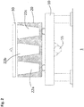
- the device 1 comprises a vibrating table 10 with a vibrating motor 15, a casting mold 20 and a pressure device 30.
- the vibrating motor 15 is provided to transmit a vibrating movement to the vibrating table 10.
- the casting mold 20 has several casting spaces 22a, 22b, 22c, which are provided for receiving fresh concrete.
- the casting spaces 22a, 22b, 22c simulate the shape of the longitudinal beams 120a, 120b, 120c (and transverse beams 140a, 140b) to be produced.
- the casting spaces 22a, 22b, 22c have trapezoidal cross-sections in order to simulate the longitudinal beams 120a, 120b, 120c, which are trapezoidal in cross-section (cf. Figures 1a and 1b ).
- the casting mold 20 is arranged on the vibrating table 10 and can be vibrated by actuating the vibrating motor 15.
- the pressure device 30 is designed to press the rubber coverings 124a, 124b, 124c on the upper side of the casting spaces 22a, 22b, 22c into the fresh concrete received in the casting spaces 22a, 22b, 22c.
- the casting mold 20 is provided (see FIG Figure 3 ).
- the casting mold 20 is arranged on the vibrating table 10, which is provided to generate a vibrating movement.
- the casting mold 20 has upwardly open casting spaces 22a, 22b, 22c, which have the shape of the longitudinal beams 120a, 120b, 120c. If the stable floor element 100 has crossbars 140a, 140b, the casting mold 20 can also have corresponding casting spaces for the crossbars 140a, 140b. These casting spaces are in the picture in Figure 2 and Figure 4 not shown.
- the open casting spaces 22a, 22b, 22c are filled with concrete (fresh concrete) up to a predetermined fill level h (see FIG Figure 4a , Filling level h) filled.
- the filling height h can be smaller than the height H of the casting spaces 22a, 22b, 22c.
- the casting mold 20 is vibrated with the aid of the vibrating motor 15 and the vibrating table 10. This results in the casting molds 22a, 22b, 22c being evenly filled with fresh concrete. In this way, the concrete cores 122a, 122b, 122c of each longitudinal beam 120a, 120b, 120c are produced.
- rubber coverings 124a, 124b, 124c are placed on the surface of the respective concrete cores 122a, 122b, 122c. This happens as long as the concrete of the concrete cores 122a, 122b, 122c is still fresh (that is, it has not yet hardened).
- the rubber coverings 124a, 124b, 124c have corresponding openings 125a, 125b, 125c as described above.
- the applied rubber coverings 124a, 124b, 124c are then pressed into the surface of the respective concrete cores 122a, 122b, 122c with the aid of the pressure device 30.
- the rubber coverings 124a, 124b, 124c are pressed into the concrete cores 122a, 122b, 122c until the desired total height of the stable floor element 100 is reached.
- the concrete (fresh concrete) of the respective concrete cores 122a, 122b, 122c displaced by the pressing process penetrates into the openings 125a, 125b, 125c and fills them. In particular, excess concrete can reach the surface via the openings 125a, 125b, 125c and escape (see Figure 4b -> excess concrete 127).
- step S50 The excess concrete 127 exiting on the surface of the rubber coverings 124a, 124b, 124c is removed in a further step S50. Furthermore, the surface at the openings 125a, 125b, 125c is smoothed out (step S60). This is how a uniform surface between the concrete penetrated in the openings 125a, 125b, 125c and the surface of the rubber floorings 124a, 124b, 124c (see Figure 4c ).
- the stable floor element 100 produced in this way is still in the casting mold 20 and has to be detached from the casting mold 20 in a further step.
- the step of releasing the stable floor element 100 from the casting mold 20 can take place as long as the concrete of the concrete cores 122a, 122b, 122c is still fresh (that is, not yet hardened).
- the detachment of the stable floor element 100 from the casting mold 20 can include the following sub-steps: Rotating the casting mold 20 such that the exposed surface of the stable floor element 100 with its rubber coverings points downwards. The stall floor element 100 can then be removed from the formwork.
- the method described so far for producing a stable floor element 100 has several advantages.
- the rubber flooring is placed and pressed in while the concrete cores of the stable floor element are being formed.
- the rubber coverings are therefore not only part of the stable floor element, but also act as a kind of cladding for the concrete cores of the stable floor element.
- by pressing the rubber coverings into the fresh concrete of the underlying concrete cores projections are created which protrude precisely into the openings in the rubber coverings and, when cured, stabilize them against slipping.
- Subsequent application of the concrete projections by gluing or screwing to the underlying concrete cores is not necessary due to the production method according to the invention.
- the production method according to the invention thus enables a faster and more cost-effective production of stable floor elements compared to known production methods.
Landscapes
- Engineering & Computer Science (AREA)
- Life Sciences & Earth Sciences (AREA)
- Manufacturing & Machinery (AREA)
- Chemical & Material Sciences (AREA)
- Ceramic Engineering (AREA)
- Mechanical Engineering (AREA)
- Architecture (AREA)
- Environmental Sciences (AREA)
- Animal Husbandry (AREA)
- Civil Engineering (AREA)
- Biodiversity & Conservation Biology (AREA)
- Zoology (AREA)
- Structural Engineering (AREA)
- Housing For Livestock And Birds (AREA)
- Floor Finish (AREA)
- Weting (AREA)
- Crystals, And After-Treatments Of Crystals (AREA)
- Led Devices (AREA)
Priority Applications (7)
| Application Number | Priority Date | Filing Date | Title |
|---|---|---|---|
| SI201830236T SI3647010T1 (sl) | 2018-10-30 | 2018-10-30 | Postopek za izdelavo elementa za hlevska tla |
| PL18203245T PL3647010T3 (pl) | 2018-10-30 | 2018-10-30 | Sposób wytwarzania elementu podłogowego do obór |
| RS20210575A RS61835B1 (sr) | 2018-10-30 | 2018-10-30 | Postupak za proizvodnju podnog elementa štale |
| HUE18203245A HUE055066T2 (hu) | 2018-10-30 | 2018-10-30 | Eljárás istállópadló-elem elõállítására |
| EP18203245.8A EP3647010B1 (de) | 2018-10-30 | 2018-10-30 | Verfahren zur herstellung eines stallbodenelements |
| DK18203245.8T DK3647010T3 (da) | 2018-10-30 | 2018-10-30 | Fremgangsmåde til fremstilling af et staldgulvselement |
| HRP20210557TT HRP20210557T1 (hr) | 2018-10-30 | 2021-04-08 | Postupak proizvodnje podnih elemenata za štale |
Applications Claiming Priority (1)
| Application Number | Priority Date | Filing Date | Title |
|---|---|---|---|
| EP18203245.8A EP3647010B1 (de) | 2018-10-30 | 2018-10-30 | Verfahren zur herstellung eines stallbodenelements |
Publications (2)
| Publication Number | Publication Date |
|---|---|
| EP3647010A1 EP3647010A1 (de) | 2020-05-06 |
| EP3647010B1 true EP3647010B1 (de) | 2021-03-03 |
Family
ID=64051468
Family Applications (1)
| Application Number | Title | Priority Date | Filing Date |
|---|---|---|---|
| EP18203245.8A Active EP3647010B1 (de) | 2018-10-30 | 2018-10-30 | Verfahren zur herstellung eines stallbodenelements |
Country Status (7)
| Country | Link |
|---|---|
| EP (1) | EP3647010B1 (da) |
| DK (1) | DK3647010T3 (da) |
| HR (1) | HRP20210557T1 (da) |
| HU (1) | HUE055066T2 (da) |
| PL (1) | PL3647010T3 (da) |
| RS (1) | RS61835B1 (da) |
| SI (1) | SI3647010T1 (da) |
Family Cites Families (5)
| Publication number | Priority date | Publication date | Assignee | Title |
|---|---|---|---|---|
| EP1563728B1 (en) | 2004-02-13 | 2006-06-07 | VAN DER VELDEN BETON, naamloze vennootschap | Method for the realisation of concrete grids for stable floors for cattle and the like. |
| PL2138289T3 (pl) * | 2008-06-23 | 2011-09-30 | Rudolf Schwarz | Sposób wytwarzania elementu rusztu ze szczelinami podłużnymi |
| DK2181585T3 (da) * | 2008-10-30 | 2013-04-08 | Betonwerk Schwarz Gmbh | Gummibelægning til et spaltegitterelement |
| DE102012112175B4 (de) * | 2012-12-12 | 2015-02-19 | Franz Aunkofer | Verfahren zur Herstellung von Böden für Tierstallungen sowie Boden für Tierstallungen |
| EP2936977B1 (en) | 2014-04-25 | 2017-02-15 | United Business Care B.V. | A stable floor element |
-
2018
- 2018-10-30 PL PL18203245T patent/PL3647010T3/pl unknown
- 2018-10-30 RS RS20210575A patent/RS61835B1/sr unknown
- 2018-10-30 SI SI201830236T patent/SI3647010T1/sl unknown
- 2018-10-30 HU HUE18203245A patent/HUE055066T2/hu unknown
- 2018-10-30 EP EP18203245.8A patent/EP3647010B1/de active Active
- 2018-10-30 DK DK18203245.8T patent/DK3647010T3/da active
-
2021
- 2021-04-08 HR HRP20210557TT patent/HRP20210557T1/hr unknown
Non-Patent Citations (1)
| Title |
|---|
| None * |
Also Published As
| Publication number | Publication date |
|---|---|
| PL3647010T3 (pl) | 2021-09-06 |
| DK3647010T3 (da) | 2021-04-12 |
| HUE055066T2 (hu) | 2021-10-28 |
| RS61835B1 (sr) | 2021-06-30 |
| EP3647010A1 (de) | 2020-05-06 |
| HRP20210557T1 (hr) | 2021-05-14 |
| SI3647010T1 (sl) | 2021-04-30 |
Similar Documents
| Publication | Publication Date | Title |
|---|---|---|
| EP0026803B1 (de) | Abschalungsvorrichtung mit einer Grundschale und mit Verbindungsstäben | |
| EP2956283B1 (de) | Verfahren zur herstellung eines mehrschichtigen, bewehrten betonelements | |
| EP2439350B1 (de) | Schalungselement | |
| EP2138289B1 (de) | Verfahren zur Herstellung eines Längsspaltenrostelements | |
| EP0519385A1 (de) | Verfahren zum Herstellen eines Abstandhalters für Bewehrungen und Abstandhalter | |
| EP3647010B1 (de) | Verfahren zur herstellung eines stallbodenelements | |
| DE602004001123T2 (de) | Verfahren zur Herstellung von Betonlängsspaltenrostelementen für Stallanlagenfussboden für Vieh und dergleichen | |
| EP2674027A2 (de) | Bodenbelagsplatte | |
| DE7709966U1 (de) | Zweischichtenplatte, insbesondere bodenplatte fuer spiel- und sportplaetze | |
| EP1605101A1 (de) | Verfahren und Vorrichtung zur Herstellung einer mehrschichtigen Platte aus Beton | |
| EP2742798B1 (de) | Verfahren zur Herstellung von Böden für Tierstallungen sowie Boden für Tierstallungen | |
| DE102004050100B3 (de) | Anordnung und Bausatz von Betonplatten für einen Stallboden, ein diese Anordnung oder diesen Bausatz umfassender Stallboden und Stall sowie Verfahren zur Herstellung des Stallbodens und Stalls | |
| EP3300870B1 (de) | Verfahren und vorrichtung zur herstellung eines längsspaltenrostelements | |
| DE3607430C2 (da) | ||
| DE202012005849U1 (de) | Bodenbelagsplatte | |
| DE202018106169U1 (de) | Einrichtung zur Stabilisierung der Stirnseiten von Betonfertigteilen | |
| WO2019030154A2 (de) | Verfahren zur herstellung eines aushärtbaren, plattenförmigen lichtkörpers, werkzeug zur durchführung des verfahrens und nach dem verfahren hergestellter lichtleitkörper | |
| DE2043071A1 (de) | Verfahren zur Herstellung von gegossenen Produkten sowie Vorrichtung zur Durchführung des Verfahrens | |
| AT227136B (de) | Vorrichtung zum Herstellen von Blöcken aus Leichtbeton | |
| DE202005019072U1 (de) | Stallboden für Rinder- und Schweineställe | |
| DE2357536C3 (de) | Verfahren zum Herstellen von Pflastersteinen aus Beton und/oder Kunststoff mit einer Gummi enthaltenden Deckschicht | |
| EP3130713B1 (de) | Bauwerk und verfahren zur herstellung eines bauwerks | |
| WO2025153676A1 (de) | Verbindungselement für einen holzbetonverbund | |
| DE202014008769U1 (de) | Spaltenbodenplatte | |
| DE2100846A1 (de) | Bei der Herstellung strukturierter Wandflächen verwendbares Modell und Verfahren zur Herstellung derartiger Flächen |
Legal Events
| Date | Code | Title | Description |
|---|---|---|---|
| PUAI | Public reference made under article 153(3) epc to a published international application that has entered the european phase |
Free format text: ORIGINAL CODE: 0009012 |
|
| STAA | Information on the status of an ep patent application or granted ep patent |
Free format text: STATUS: REQUEST FOR EXAMINATION WAS MADE |
|
| 17P | Request for examination filed |
Effective date: 20190917 |
|
| AK | Designated contracting states |
Kind code of ref document: A1 Designated state(s): AL AT BE BG CH CY CZ DE DK EE ES FI FR GB GR HR HU IE IS IT LI LT LU LV MC MK MT NL NO PL PT RO RS SE SI SK SM TR |
|
| AX | Request for extension of the european patent |
Extension state: BA ME |
|
| RIC1 | Information provided on ipc code assigned before grant |
Ipc: B28B 7/18 20060101ALI20200901BHEP Ipc: E04C 2/42 20060101ALI20200901BHEP Ipc: A01K 1/015 20060101ALI20200901BHEP Ipc: B28B 3/02 20060101AFI20200901BHEP Ipc: B28B 23/00 20060101ALI20200901BHEP |
|
| GRAP | Despatch of communication of intention to grant a patent |
Free format text: ORIGINAL CODE: EPIDOSNIGR1 |
|
| STAA | Information on the status of an ep patent application or granted ep patent |
Free format text: STATUS: GRANT OF PATENT IS INTENDED |
|
| INTG | Intention to grant announced |
Effective date: 20201029 |
|
| GRAS | Grant fee paid |
Free format text: ORIGINAL CODE: EPIDOSNIGR3 |
|
| GRAA | (expected) grant |
Free format text: ORIGINAL CODE: 0009210 |
|
| STAA | Information on the status of an ep patent application or granted ep patent |
Free format text: STATUS: THE PATENT HAS BEEN GRANTED |
|
| AK | Designated contracting states |
Kind code of ref document: B1 Designated state(s): AL AT BE BG CH CY CZ DE DK EE ES FI FR GB GR HR HU IE IS IT LI LT LU LV MC MK MT NL NO PL PT RO RS SE SI SK SM TR |
|
| REG | Reference to a national code |
Ref country code: GB Ref legal event code: FG4D Free format text: NOT ENGLISH |
|
| REG | Reference to a national code |
Ref country code: CH Ref legal event code: EP Ref country code: CH Ref legal event code: NV Representative=s name: ING. MARCO ZARDI C/O M. ZARDI AND CO. S.A., CH Ref country code: AT Ref legal event code: REF Ref document number: 1366711 Country of ref document: AT Kind code of ref document: T Effective date: 20210315 |
|
| REG | Reference to a national code |
Ref country code: DE Ref legal event code: R096 Ref document number: 502018004115 Country of ref document: DE |
|
| REG | Reference to a national code |
Ref country code: IE Ref legal event code: FG4D Free format text: LANGUAGE OF EP DOCUMENT: GERMAN |
|
| REG | Reference to a national code |
Ref country code: HR Ref legal event code: TUEP Ref document number: P20210557T Country of ref document: HR |
|
| REG | Reference to a national code |
Ref country code: DK Ref legal event code: T3 Effective date: 20210407 |
|
| REG | Reference to a national code |
Ref country code: NL Ref legal event code: FP |
|
| REG | Reference to a national code |
Ref country code: SK Ref legal event code: T3 Ref document number: E 36858 Country of ref document: SK |
|
| REG | Reference to a national code |
Ref country code: HR Ref legal event code: T1PR Ref document number: P20210557 Country of ref document: HR |
|
| REG | Reference to a national code |
Ref country code: SE Ref legal event code: TRGR |
|
| REG | Reference to a national code |
Ref country code: LT Ref legal event code: MG9D |
|
| PG25 | Lapsed in a contracting state [announced via postgrant information from national office to epo] |
Ref country code: NO Free format text: LAPSE BECAUSE OF FAILURE TO SUBMIT A TRANSLATION OF THE DESCRIPTION OR TO PAY THE FEE WITHIN THE PRESCRIBED TIME-LIMIT Effective date: 20210603 Ref country code: LT Free format text: LAPSE BECAUSE OF FAILURE TO SUBMIT A TRANSLATION OF THE DESCRIPTION OR TO PAY THE FEE WITHIN THE PRESCRIBED TIME-LIMIT Effective date: 20210303 Ref country code: FI Free format text: LAPSE BECAUSE OF FAILURE TO SUBMIT A TRANSLATION OF THE DESCRIPTION OR TO PAY THE FEE WITHIN THE PRESCRIBED TIME-LIMIT Effective date: 20210303 Ref country code: GR Free format text: LAPSE BECAUSE OF FAILURE TO SUBMIT A TRANSLATION OF THE DESCRIPTION OR TO PAY THE FEE WITHIN THE PRESCRIBED TIME-LIMIT Effective date: 20210604 Ref country code: BG Free format text: LAPSE BECAUSE OF FAILURE TO SUBMIT A TRANSLATION OF THE DESCRIPTION OR TO PAY THE FEE WITHIN THE PRESCRIBED TIME-LIMIT Effective date: 20210603 |
|
| PG25 | Lapsed in a contracting state [announced via postgrant information from national office to epo] |
Ref country code: LV Free format text: LAPSE BECAUSE OF FAILURE TO SUBMIT A TRANSLATION OF THE DESCRIPTION OR TO PAY THE FEE WITHIN THE PRESCRIBED TIME-LIMIT Effective date: 20210303 |
|
| REG | Reference to a national code |
Ref country code: HU Ref legal event code: AG4A Ref document number: E055066 Country of ref document: HU |
|
| PG25 | Lapsed in a contracting state [announced via postgrant information from national office to epo] |
Ref country code: SM Free format text: LAPSE BECAUSE OF FAILURE TO SUBMIT A TRANSLATION OF THE DESCRIPTION OR TO PAY THE FEE WITHIN THE PRESCRIBED TIME-LIMIT Effective date: 20210303 Ref country code: EE Free format text: LAPSE BECAUSE OF FAILURE TO SUBMIT A TRANSLATION OF THE DESCRIPTION OR TO PAY THE FEE WITHIN THE PRESCRIBED TIME-LIMIT Effective date: 20210303 |
|
| REG | Reference to a national code |
Ref country code: HR Ref legal event code: ODRP Ref document number: P20210557 Country of ref document: HR Payment date: 20210928 Year of fee payment: 4 |
|
| PG25 | Lapsed in a contracting state [announced via postgrant information from national office to epo] |
Ref country code: RO Free format text: LAPSE BECAUSE OF FAILURE TO SUBMIT A TRANSLATION OF THE DESCRIPTION OR TO PAY THE FEE WITHIN THE PRESCRIBED TIME-LIMIT Effective date: 20210303 Ref country code: PT Free format text: LAPSE BECAUSE OF FAILURE TO SUBMIT A TRANSLATION OF THE DESCRIPTION OR TO PAY THE FEE WITHIN THE PRESCRIBED TIME-LIMIT Effective date: 20210705 Ref country code: IS Free format text: LAPSE BECAUSE OF FAILURE TO SUBMIT A TRANSLATION OF THE DESCRIPTION OR TO PAY THE FEE WITHIN THE PRESCRIBED TIME-LIMIT Effective date: 20210703 |
|
| REG | Reference to a national code |
Ref country code: DE Ref legal event code: R097 Ref document number: 502018004115 Country of ref document: DE |
|
| PLBE | No opposition filed within time limit |
Free format text: ORIGINAL CODE: 0009261 |
|
| STAA | Information on the status of an ep patent application or granted ep patent |
Free format text: STATUS: NO OPPOSITION FILED WITHIN TIME LIMIT |
|
| PG25 | Lapsed in a contracting state [announced via postgrant information from national office to epo] |
Ref country code: ES Free format text: LAPSE BECAUSE OF FAILURE TO SUBMIT A TRANSLATION OF THE DESCRIPTION OR TO PAY THE FEE WITHIN THE PRESCRIBED TIME-LIMIT Effective date: 20210303 Ref country code: AL Free format text: LAPSE BECAUSE OF FAILURE TO SUBMIT A TRANSLATION OF THE DESCRIPTION OR TO PAY THE FEE WITHIN THE PRESCRIBED TIME-LIMIT Effective date: 20210303 |
|
| 26N | No opposition filed |
Effective date: 20211206 |
|
| PG25 | Lapsed in a contracting state [announced via postgrant information from national office to epo] |
Ref country code: IS Free format text: LAPSE BECAUSE OF FAILURE TO SUBMIT A TRANSLATION OF THE DESCRIPTION OR TO PAY THE FEE WITHIN THE PRESCRIBED TIME-LIMIT Effective date: 20210703 |
|
| PG25 | Lapsed in a contracting state [announced via postgrant information from national office to epo] |
Ref country code: MC Free format text: LAPSE BECAUSE OF FAILURE TO SUBMIT A TRANSLATION OF THE DESCRIPTION OR TO PAY THE FEE WITHIN THE PRESCRIBED TIME-LIMIT Effective date: 20210303 |
|
| PG25 | Lapsed in a contracting state [announced via postgrant information from national office to epo] |
Ref country code: FR Free format text: LAPSE BECAUSE OF NON-PAYMENT OF DUE FEES Effective date: 20211031 |
|
| PG25 | Lapsed in a contracting state [announced via postgrant information from national office to epo] |
Ref country code: IE Free format text: LAPSE BECAUSE OF NON-PAYMENT OF DUE FEES Effective date: 20211030 |
|
| REG | Reference to a national code |
Ref country code: HR Ref legal event code: ODRP Ref document number: P20210557 Country of ref document: HR Payment date: 20220926 Year of fee payment: 5 |
|
| GBPC | Gb: european patent ceased through non-payment of renewal fee |
Effective date: 20221030 |
|
| PG25 | Lapsed in a contracting state [announced via postgrant information from national office to epo] |
Ref country code: CY Free format text: LAPSE BECAUSE OF FAILURE TO SUBMIT A TRANSLATION OF THE DESCRIPTION OR TO PAY THE FEE WITHIN THE PRESCRIBED TIME-LIMIT Effective date: 20210303 |
|
| PG25 | Lapsed in a contracting state [announced via postgrant information from national office to epo] |
Ref country code: GB Free format text: LAPSE BECAUSE OF NON-PAYMENT OF DUE FEES Effective date: 20221030 |
|
| REG | Reference to a national code |
Ref country code: HR Ref legal event code: ODRP Ref document number: P20210557 Country of ref document: HR Payment date: 20230920 Year of fee payment: 6 |
|
| PG25 | Lapsed in a contracting state [announced via postgrant information from national office to epo] |
Ref country code: MK Free format text: LAPSE BECAUSE OF FAILURE TO SUBMIT A TRANSLATION OF THE DESCRIPTION OR TO PAY THE FEE WITHIN THE PRESCRIBED TIME-LIMIT Effective date: 20210303 |
|
| PG25 | Lapsed in a contracting state [announced via postgrant information from national office to epo] |
Ref country code: MT Free format text: LAPSE BECAUSE OF FAILURE TO SUBMIT A TRANSLATION OF THE DESCRIPTION OR TO PAY THE FEE WITHIN THE PRESCRIBED TIME-LIMIT Effective date: 20210303 |
|
| REG | Reference to a national code |
Ref country code: HR Ref legal event code: ODRP Ref document number: P20210557 Country of ref document: HR Payment date: 20240924 Year of fee payment: 7 |
|
| PGFP | Annual fee paid to national office [announced via postgrant information from national office to epo] |
Ref country code: PL Payment date: 20250807 Year of fee payment: 8 |
|
| PGFP | Annual fee paid to national office [announced via postgrant information from national office to epo] |
Ref country code: HR Payment date: 20250926 Year of fee payment: 8 |
|
| PGFP | Annual fee paid to national office [announced via postgrant information from national office to epo] |
Ref country code: CZ Payment date: 20250926 Year of fee payment: 8 Ref country code: RS Payment date: 20250924 Year of fee payment: 8 |
|
| PGFP | Annual fee paid to national office [announced via postgrant information from national office to epo] |
Ref country code: SK Payment date: 20250926 Year of fee payment: 8 |
|
| PGFP | Annual fee paid to national office [announced via postgrant information from national office to epo] |
Ref country code: SI Payment date: 20250925 Year of fee payment: 8 |
|
| REG | Reference to a national code |
Ref country code: CH Ref legal event code: U11 Free format text: ST27 STATUS EVENT CODE: U-0-0-U10-U11 (AS PROVIDED BY THE NATIONAL OFFICE) Effective date: 20251101 |
|
| REG | Reference to a national code |
Ref country code: HR Ref legal event code: ODRP Ref document number: P20210557 Country of ref document: HR Payment date: 20250926 Year of fee payment: 8 |
|
| PGFP | Annual fee paid to national office [announced via postgrant information from national office to epo] |
Ref country code: HU Payment date: 20251007 Year of fee payment: 8 |
|
| PGFP | Annual fee paid to national office [announced via postgrant information from national office to epo] |
Ref country code: LU Payment date: 20251021 Year of fee payment: 8 Ref country code: NL Payment date: 20251024 Year of fee payment: 8 |
|
| PG25 | Lapsed in a contracting state [announced via postgrant information from national office to epo] |
Ref country code: TR Free format text: LAPSE BECAUSE OF FAILURE TO SUBMIT A TRANSLATION OF THE DESCRIPTION OR TO PAY THE FEE WITHIN THE PRESCRIBED TIME-LIMIT Effective date: 20210303 |
|
| PGFP | Annual fee paid to national office [announced via postgrant information from national office to epo] |
Ref country code: DE Payment date: 20250926 Year of fee payment: 8 |
|
| PGFP | Annual fee paid to national office [announced via postgrant information from national office to epo] |
Ref country code: AT Payment date: 20251023 Year of fee payment: 8 |
|
| PGFP | Annual fee paid to national office [announced via postgrant information from national office to epo] |
Ref country code: DK Payment date: 20251024 Year of fee payment: 8 Ref country code: IT Payment date: 20251030 Year of fee payment: 8 |
|
| PGFP | Annual fee paid to national office [announced via postgrant information from national office to epo] |
Ref country code: BE Payment date: 20251024 Year of fee payment: 8 |
|
| PGFP | Annual fee paid to national office [announced via postgrant information from national office to epo] |
Ref country code: CH Payment date: 20251101 Year of fee payment: 8 Ref country code: SE Payment date: 20251024 Year of fee payment: 8 |