EP3646342B1 - Isolation condenser systems for very simplified boiling water reactors - Google Patents
Isolation condenser systems for very simplified boiling water reactors Download PDFInfo
- Publication number
- EP3646342B1 EP3646342B1 EP18824938.7A EP18824938A EP3646342B1 EP 3646342 B1 EP3646342 B1 EP 3646342B1 EP 18824938 A EP18824938 A EP 18824938A EP 3646342 B1 EP3646342 B1 EP 3646342B1
- Authority
- EP
- European Patent Office
- Prior art keywords
- isolation
- coolant
- reactor
- isolation condenser
- chamber
- Prior art date
- Legal status (The legal status is an assumption and is not a legal conclusion. Google has not performed a legal analysis and makes no representation as to the accuracy of the status listed.)
- Active
Links
Images


Classifications
-
- G—PHYSICS
- G21—NUCLEAR PHYSICS; NUCLEAR ENGINEERING
- G21C—NUCLEAR REACTORS
- G21C15/00—Cooling arrangements within the pressure vessel containing the core; Selection of specific coolants
- G21C15/18—Emergency cooling arrangements; Removing shut-down heat
-
- G—PHYSICS
- G21—NUCLEAR PHYSICS; NUCLEAR ENGINEERING
- G21C—NUCLEAR REACTORS
- G21C15/00—Cooling arrangements within the pressure vessel containing the core; Selection of specific coolants
- G21C15/02—Arrangements or disposition of passages in which heat is transferred to the coolant; Coolant flow control devices
-
- G—PHYSICS
- G21—NUCLEAR PHYSICS; NUCLEAR ENGINEERING
- G21C—NUCLEAR REACTORS
- G21C17/00—Monitoring; Testing ; Maintaining
- G21C17/02—Devices or arrangements for monitoring coolant or moderator
- G21C17/035—Moderator- or coolant-level detecting devices
-
- G—PHYSICS
- G21—NUCLEAR PHYSICS; NUCLEAR ENGINEERING
- G21C—NUCLEAR REACTORS
- G21C15/00—Cooling arrangements within the pressure vessel containing the core; Selection of specific coolants
- G21C15/16—Cooling arrangements within the pressure vessel containing the core; Selection of specific coolants comprising means for separating liquid and steam
-
- G—PHYSICS
- G21—NUCLEAR PHYSICS; NUCLEAR ENGINEERING
- G21C—NUCLEAR REACTORS
- G21C15/00—Cooling arrangements within the pressure vessel containing the core; Selection of specific coolants
- G21C15/24—Promoting flow of the coolant
- G21C15/26—Promoting flow of the coolant by convection, e.g. using chimneys, using divergent channels
-
- G—PHYSICS
- G21—NUCLEAR PHYSICS; NUCLEAR ENGINEERING
- G21C—NUCLEAR REACTORS
- G21C9/00—Emergency protection arrangements structurally associated with the reactor, e.g. safety valves provided with pressure equalisation devices
- G21C9/04—Means for suppressing fires ; Earthquake protection
-
- Y—GENERAL TAGGING OF NEW TECHNOLOGICAL DEVELOPMENTS; GENERAL TAGGING OF CROSS-SECTIONAL TECHNOLOGIES SPANNING OVER SEVERAL SECTIONS OF THE IPC; TECHNICAL SUBJECTS COVERED BY FORMER USPC CROSS-REFERENCE ART COLLECTIONS [XRACs] AND DIGESTS
- Y02—TECHNOLOGIES OR APPLICATIONS FOR MITIGATION OR ADAPTATION AGAINST CLIMATE CHANGE
- Y02E—REDUCTION OF GREENHOUSE GAS [GHG] EMISSIONS, RELATED TO ENERGY GENERATION, TRANSMISSION OR DISTRIBUTION
- Y02E30/00—Energy generation of nuclear origin
- Y02E30/30—Nuclear fission reactors
Definitions
- FIG. 1 is a schematic of a containment building 36 that houses a reactor pressure vessel 42 with various configurations of fuel 41 and reactor internals for producing nuclear power in a related art economic simplified boiling water reactor (ESBWR).
- Reactor 42 is conventionally capable of producing and approved to produce several thousand megawatts of thermal energy through nuclear fission.
- Reactor 42 sits in a drywell 51, including upper drywell 54 and a lower drywell 3 that provides space surrounding and under reactor 42 for external components and personnel.
- Reactor 42 is typically several dozen meters high, and containment building 36 even higher above ground elevation, to facilitate natural circulation cooling and construction from ground level.
- a sacrificial melt layer 1 called a basemat-internal melt arrest and coolability device, is positioned directly below reactor 42 to cool potential falling debris, melted reactor structures, and/or coolant and prevent their progression into a ground below containment 36.
- containment 36 may include a pressure suppression chamber 58 surrounding reactor 42 in an annular or other fashion and holding suppression pool 59.
- Suppression pool 59 may include an emergency steam vent used to divert steam from a main steam line into suppression pool 59 for condensation and heat sinking, to prevent over-heating and over-pressurization of containment 36.
- Suppression pool 59 may also include flow paths that allow fluid flowing into drywell 54 to drain, or be pumped, into suppression pool 59.
- Suppression pool 59 may further include other heat-exchangers or drains configured to remove heat or pressure from containment 36 following a loss of coolant accident.
- An emergency core cooling system line and pump 10 may inject coolant from suppression pool 59 into reactor 42 to make up lost feedwater and/or other emergency coolant supply.
- a gravity-driven cooling system (GDCS) pool 37 can further provide coolant to reactor 42 via piping 57.
- a passive containment cooling system (PCCS) pool 65 may condense any steam inside containment 36, such as steam created through reactor depressurization to lower containment pressure or a main steam line break, and feed the condensed fluid back into GDCS pool 37.
- An isolation cooling system (ICS) pool 66 may take steam directly at pressure from reactor 42 and condense the same for recirculation back into rector 42.
- ESBWR ESBWR Plant General Description
- Example embodiments include nuclear reactors with an isolation condenser system connecting to the nuclear reactor through integrally isolatable connections that have a minimal risk of leakage or failure. In this way, example nuclear reactors may be effectively completely isolated from the isolation condenser system.
- Example embodiment isolation condenser systems include one or more isolation condensers immersed in a segregated coolant such that the condenser can transfer heat to the immersive coolant when receiving a working coolant or moderator from the nuclear reactor.
- the immersive coolant can be drawn from a separate coolant reservoir that supplies one or more separate isolation condensers.
- Barriers may prevent flow between the various isolation condensers; for example, a check valve may permit coolant to flow only from the reservoir to the isolation condenser and separate the two if the immersive coolant level becomes too high, too hot, too radioactive, etc. about the isolation condenser.
- a switch can passively monitor coolant level between the isolation condenser and reservoir, selectively permitting flow based on relative elevation of floats in the reservoir and coolant surrounding the isolation condenser. Movement of the floats may actuate the check valve and/or the isolation condenser itself. Isolation condensers in example systems can be activated by opening a fluid loop through the condenser to/from the reactor.
- fluidic controls and/or a pressure pulse transmitter may monitor reactor conditions and selectively activate individual isolation condensers, trip and/or isolate the reactor, and/or trip the rest of the plant based on detected reactor pressures, coolant levels, etc.
- passive and reliable sensors may place the plant in a safe shutdown condition with indefinite cooling capacity if operations divert from design bases.
- Example embodiment isolation condenser systems may be positioned outside of containment in an underground silo with the containment, which may not have any other coolant source.
- auxiliary or emergency coolant systems typically require powered, digital controls to activate and operate in nuclear reactors. Such emergency systems typically require pumps and/or active valves and monitors for proper operation. With several, diverse coolant systems, complex logic and controls may be required to achieve activation protocols and selectively activate individual safety systems. These systems are typically positioned inside containment for immediate reactor access, requiring a large and complex containment. To overcome these newly-recognized problems as well as others, the inventors have developed example embodiments and methods described below to address these and other problems recognized by the inventors with unique solutions enabled by example embodiments.
- the present invention is isolation cooling systems, plants containing the same, and methods of operating such systems and plants.
- the few example embodiments and example methods discussed below illustrate just a subset of the variety of different configurations that can be used as and/or in connection with the present invention.
- FIG. 2 is a schematic of an example embodiment reactor system 100 including example embodiment reactor 142, example embodiment containment 136, and related cooling and power generation systems.
- System 100 is similarly described in co-owned US published patent application number 2018/0322966to Hunt, Dahlgren, and Marquino, filed May 2, 2017 for VERY SIMPLIFIED BOILING WATER REACTORS FOR COMMERCIAL ELECTRICITY GENERATION.
- example embodiment system 100 is useable with conventional and known power generating equipment such as high- and low-pressure turbines, electrical generators, switchyards, condensers, cooling towers or heat sinks, etc., which may connect, for example to main feedwater line 120 and main steam line 125 in a similar fashion to any power generation facility.
- Example embodiment containment 136 is composed of resilient, impermeable material for limiting migration of radioactive material and plant components in the case of a transient or accident scenario.
- containment 136 may be an integrally-formed concrete structure, potentially with reinforcing internal steel or rebar skeleton, several inches or feet thick.
- an all-steel body may be used without being prohibitively expensive or complexly-fabricated, to enhance strength, radiation shielding, and lifespan of containment 136.
- example embodiment containment 136 may be underground, potentially housed in a reactor silo 190.
- a concrete lid 191 or other surface shield level with, or below, ground 90 may enclose silo 190 housing example embodiment reactor 142 and containment 136.
- Silo 190 and lid 191 may be seismically isolated or hardened to minimize any shock wave encountered from the ground and thus minimize impact of seismic events on reactor 142 and systems in silo 190 such as example ICS 300 and/or control system 165.
- example embodiment system 100 may present an exceedingly small strike target and/or be hardened against surface impacts and explosions. Further, if underground, example embodiment system 100 may have additional containment against radioactive release and enable easier flooding in the case of emergency cooling.
- any electricity-generating equipment may be connected above ground without loss of these benefits, and/or such equipment may also be placed below ground.
- example embodiment containment 136 may be compact and simplified relative to existing nuclear power plants, including the ESBWR.
- Conventional operating and emergency equipment including a GDCS, PCCS, suppression pools, Bimacs, backup batteries, wetwells, torii, etc. may be wholly omitted from containment 136.
- Containment 136 may be accessible through fewer access points as well, such as a single top access point under shield 191 that permits access to reactor 142 for refueling and maintenance.
- example embodiment reactor 142 and core 141 may not require a bimac for floor arrest and cooling, because no realistic scenario exists for fuel relocation into containment 136; nonetheless, example embodiment containment 136 may have sufficient floor thickness and spread area to accommodate and cool any relocated core in its entirety, as shown in FIG. 2 . Moreover, total penetrations through containment 136 may be minimized and or isolated to reduce or effectively eliminate risk of leakage from containment 136.
- Example embodiment reactor 142 may be a boiling-water type reactor, similar to approved ESBWR designs in reactor internals and height. Reactor 142 may be smaller than, such as one-fifth the volume of, ESBWRs, producing only up to 600 megawatts of electricity for example, with a proportionally smaller core 141, for example operating at less than 1000 megawatt-thermal. For example, example embodiment reactor 142 may be almost 28 meters in height and slightly over 3 meters in diameter, with internals matching ESBWR internals but scaled down proportionally in the transverse direction to operate at approximately 900 megawatt-thermal and 300 megawatt-electric ratings.
- reactor 142 may be a same proportion as an ESBWR, with an approximate 3.9 height-to-width ratio, scaled down to a smaller volume.
- other dimensions are useable with example embodiment reactor 142, with smaller height-to-width ratios such as 2.7, or 2.0, that may enable natural circulation at smaller sizes or proper flow path configuration inside the reactor.
- example embodiment reactor 142 may preserve natural circulation effects achieved by known ESBWRs in example embodiment reactor 142.
- smaller reactor 142 may more easily be positioned underground with associated cooling equipment and/or possess less overheating and damage risk due to smaller fuel inventory in core 141.
- smaller example embodiment reactor 142 with lower power rating may more readily satisfy modular power or peaking power demands, with easier startup, shutdown, and/or reduced power operations to better match energy demand.
- a coolant loop such as main feedwater line 120 and main steam line 125, may flow into reactor 142 to provide moderator, coolant, and/or heat transfer fluid for electricity generation.
- An emergency coolant source such as one or more example embodiment isolation condenser systems (ICS) 300, may further provide emergency cooling to reactor 142 in the instance of loss of feedwater from line 120.
- Example embodiment ICS 300 may include steam inlet 162 from example embodiment reactor 142 and condensate return 163 to reactor 142. Each of these connections to reactor 142 may use isolation valves 200 that are integrally connected to reactor 142 inside containment 136 and represent negligible failure risk.
- example embodiment containment 136 may be sealed about any other valve or penetration, such as power systems, instrumentation, coolant cleanup lines, etc.
- the fewer penetrations, smaller size, lack of systems inside, and/or underground placement of containment 136 may permit a higher operating pressure, potentially up to near reactor pressures of several hundred, such as 300, psig without any leakage potential.
- example embodiment reactor system 100 several different features permit significantly decreased loss of coolant probability, enable responsive and flexible power generation, reduce plant footprint and above-ground strike target, and/or simplify nuclear plant construction and operation.
- example embodiment reactor 142 may still benefit from passive safety features such as natural circulation inherent in the ESBWR design, while allowing a significantly smaller and simplified example embodiment containment 136 and reliance on passive isolation condensers 166 for emergency heat removal.
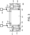
- FIG. 3 is an illustration of an example embodiment ICS 300 useable in example embodiment plant 100.
- example embodiment ICS 300 may include multiple isolation condensers 310, 320, etc. in fluid connection with a large reservoir or ICS pool 301.
- first isolation condenser 310 and a second isolation condenser 320 are shown in FIG. 3 , it is understood that any number of isolation condenser(s) may feed from ICS pool 301.
- Each isolation condenser 310 and 320 may include its own ICS chambers 311 and 321 with independent coolant control and levels that may be replenished by ICS pool 301. Because ICS 300 may be outside of any containment, ICS pool 301, isolation condensers 310 and 320, and any other component of ICS 300 may be easily reached for maintenance, inspection, emergency refill, and/or operation, regardless of plant state.
- each isolation condenser 310 and 320 may be fed by steam inlet 162 providing steam produced in the nuclear reactor.
- the steam may pass down through a heat exchanger in isolation condenser 310 transferring heat to a fluid, such as water, in chamber 311 that condenses the steam back to liquid water.
- Condensate return line 163 then allows this condensed water to flow back into the reactor, driven by gravity, steam inertia, and density gradient between the steam and condensed water.
- Isolation condensers 310 and 320 may use a double, split loop through two, multi-channel heat exchangers as shown in FIG. 3 , or use other known designs, such as ICS designs from approved ESBWR plants or others.
- isolation condenser 310 may have cooling capacity for the entire reactor. That is, isolation condensers 310 and 320 may each be able to condense a full volume of steam produced by an example embodiment lower power reactor to maintain a steady liquid level in the same. Similarly, isolation condensers may have lower and/or varying capacities and be used in any number to provide a margin of safety, such as four total condensers each with a condensing capacity of 75% total core flow for a 3x safety margin.
- each isolation condenser 310 and 320 is shown with its own steam line 162 and condensate return line 163, it is understood that actual supply and return may branch from a shared steam 162 and condensate return 163 line, so as to require only a single isolation valve 200 ( FIG. 2 ) for all of ICS 300 having multiple isolation condensers 310, 320.
- Control of each isolation condenser may be individualized as discussed below through valves on steam line 162 and/or condensate return line 163.
- first isolation condenser 310 and second isolation condenser 320 may each use an individual steam line 162 and condensate return line 163 with separate isolation valves 200, such as in the example of FIG. 2 .
- each isolation condenser 310 and 320 may use its own chamber 311 and 321, respectively, coolant levels may be maintained for each, despite drawing from a common pool 301.
- check valves 340 between pool 301 and chamber 311 may permit only one-way flow from pool 301 into chamber 311. In this way, evaporation or boil-off from chamber 311 may be replenished from pool 301 without necessarily lowering or affecting levels in other chamber 321. Similarly, if chamber 311 is at a higher fill level, check valves 340 may not allow coolant to flow out into pool 301.
- Passive switch 330 may detect when an ICS chamber should be isolated via check valve 340 or other connections to pool 301, without active or DCIS controls. Passive switch 330 may further indicate when an isolation condenser 311, 321, etc. should be deactivated. For example, passive switch 330 may use two floats, 331, one in pool 301 and another in ICS chamber 311. As floats move on the surface of the coolant, such as liquid water, they may move a position of switch 330 when joined on either side of a pivot.
- coolant level in ICS chamber 311 is lower than pool 301, this may be reflected in positioning of floats 331, and switch 330 may open (shown by an arrow) check valve 340 between floats 331 and keep isolation condenser 310 active and ICS chamber 311 replenished. Or for example, as coolant level in ICS chamber 321 exceeds a level in pool 301, this may indicate malfunction or rupture in isolation condenser 320 where reactor coolant may be entering ICS chamber 321.
- Floats 331 in an opposite vertical relative positioning in this circumstance may close switch 330, which may close check valve 340 (shown by an X) and potentially deactivate or isolate isolation condenser 320 to prevent further reactor leakage and/or coolant flow into ICS chamber 321 and pool 301.
- floats 331 are used by passive switch 330 in FIG. 3 , it is understood that other passive or low-failure-mode devices can be used to detect abnormal or undesired conditions of isolation condensers and their chambers.
- passive switch 330 or another detector may detect additional ICS cooling or condensation is necessary, such as if chamber 321 has approached boiling, and activate additional isolation condensers.
- additional isolating structures may be actuated upon detection of undesired operating conditions in example embodiment ICS 300, such as inoperable or leaking isolation condenser 320 requiring isolation of chamber 321. Additional modes of activating and deactivating isolation condensers 310 and 320 are discussed below in connection with FIG. 4 .
- FIG. 4 is an illustration of an example embodiment selective activation and isolation system 165.
- example embodiment system 165 may connect to or be interfaced with reactor 142, valves 200, ICS 300, and/or containment 136 to control operation of the same.
- activation and isolation system 165 may include multiple fluidic controls 166A, 166B, etc. each interfaced with an isolation condenser 310, 320, etc. Although only two fluidic controls and two isolation condensers are shown in FIG. 4 , it is understood that any number may be used.
- Fluidic controls 166A and 166B may connect to reactor 142 through a shared pressure line 143. Pressure line 143 may extend through containment with appropriate penetration seal or fluidic controls 166 may be inside containment.
- fluidic control 166A may activate isolation condenser 310.
- the pressure setpoint may be a high pressure associated with reactor overheat or isolation from feedwater or turbine loss, for example.
- Fluidic control 166A may be configured to directly actuate a valve, rupture an accumulator, passively use reactor pressure to open a valve, and/or otherwise reliably open a coolant loop to isolation condenser 310 at the setpoint.
- the actuated valve may be a valve on the condensate return line 163; for example, the valve may be an isolation valve 200 ( FIG.
- Fluidic control 166A may further actuate a valve on steam inlet 162, or it is also possible that steam inlet 162 is always open to isolation condenser 310, such that opening only a single valve for condensate return 163 causes flow through isolation condenser 310, already at reactor pressure to prevent water hammer.
- Another fluidic control 166B may open a valve associated with another isolation condenser 320 at the setpoint.
- fluidic control 166B may have a higher pressure activation setpoint, such that isolation condenser 320 is only activated if the setpoint for activation of fluidic control 166A for isolation condenser 310 has already been activated.
- isolation condenser 310 may be leaking or not working, as determined by passive switch 330 ( FIG. 3 ), which may re-close the valve opened by fluidic control 166A, deactivate fluidic control 166A, close another valve such as a steam inlet valve for condenser 310, or otherwise take isolation condenser 310 offline.
- isolation condenser 310 is inadequate, inoperable, or deactivated, pressure in reactor 142 may rise again without any cooling or condensing system, particularly if reactor 142 ( FIG. 2 ) is isolated by isolation valves 200 in the event of a transient. Eventually the pressure will rise to the higher setpoint of fluidic control 166B, which will activate isolation condenser 320 and provide pressure relief and cooling. This setup may be repeated for any number or independently-operable fluidic controls 166 at any number of different, desired pressure setpoints, to provide a throttled and redundant amount of heat removal and condensation to reactor 142.
- pressure pulse transmitter 167 is interfaced with reactor 142 through a reactor fluid line 144. Pressure pulse transmitter 167 may similarly activate one or all isolation condensers 310, 320, etc. Pressure pulse transmitter 167 may be a passive instrument that detects water level in reactor 142 and can, through hydraulic pressure, open and/or close any valve, including isolation valves 200, to activate isolation condenser 310 and/or 320, isolate reactor 142 from main steam line 125, isolate reactor 142 from main feedwater line 120, etc. Pressure pulse transmitter 167 may be of a type described in "Passive Pressure Pulse Transmitter" by Areva, or another known type of pressure pulse transmitter.
- Pressure pulse transmitter 167 may actuate valves based on water level in reactor 142 instead of pressure. As such, pressure pulse transmitter 167 may offer an alternative and independent metric of reactor functionality and safety on which to trigger safety functions. For example, pressure pulse transmitter 167 may detect an abnormal water level approaching a top of the reactor core or fuel, at which point all isolation condensers 310, 320, etc. may be activated by opening valves associated with the same. Or, for example, pressure pulse transmitter 167 may be configured with several water level setpoints to selectively activate or turn off systems, such as isolation condenser 310 at a first low reactor coolant level, isolation condenser 320 at a second lower reactor coolant level, etc. Still further, pressure pulse transmitter 167 may deactivate isolation condensers 310, 320, etc. or shut ICS valves on a condensate return line 163 or steam inlet 162 at detection of a high reactor coolant level.
- fluidic controls 166 and/or pressure pulse transmitter 167 in example embodiment selective activation and isolation system 165 may also interface with isolation valves 200 that isolate reactor 142 from main feedwater line 120 and/or main steam line 125, in addition to valves associated with isolation condensers 310, 320.
- Control connections 168 are used to illustrate operative control over the various valves controlling flow to isolation condensers, main steam, feedwater, etc.; it is understood that control connections may be contained in a single body with fluidic controls and manipulated valve or may be an actuator line or other powered connection that opens or closes the valve, for example.
- fluidic controls 166 and/or pressure pulse transmitter 167 may use control logic to selectively open or close combinations of valves to place a plant in a desired configuration. For example, along with actuation of ICS 300, isolation valves 200 for main feedwater 120 and main steam outlet 125 may be closed to isolate reactor 142 by a single fluidic control 166A or transmitter 167. Or, different fluidic controls 166 may place the plant in differing configurations including triggering a reactor scram and/or main turbine trip, based on worsening detected pressure.
Landscapes
- Physics & Mathematics (AREA)
- Engineering & Computer Science (AREA)
- Plasma & Fusion (AREA)
- General Engineering & Computer Science (AREA)
- High Energy & Nuclear Physics (AREA)
- Structure Of Emergency Protection For Nuclear Reactors (AREA)
Applications Claiming Priority (2)
| Application Number | Priority Date | Filing Date | Title |
|---|---|---|---|
| US15/635,400 US10867712B2 (en) | 2017-06-28 | 2017-06-28 | Isolation condenser systems for nuclear reactor commercial electricity generation |
| PCT/US2018/036894 WO2019005465A1 (en) | 2017-06-28 | 2018-06-11 | ISOLATION CAPACITOR SYSTEMS FOR VERY SIMPLIFIED BOILER WATER REACTORS |
Publications (3)
| Publication Number | Publication Date |
|---|---|
| EP3646342A1 EP3646342A1 (en) | 2020-05-06 |
| EP3646342A4 EP3646342A4 (en) | 2021-02-24 |
| EP3646342B1 true EP3646342B1 (en) | 2024-10-02 |
Family
ID=64739032
Family Applications (1)
| Application Number | Title | Priority Date | Filing Date |
|---|---|---|---|
| EP18824938.7A Active EP3646342B1 (en) | 2017-06-28 | 2018-06-11 | Isolation condenser systems for very simplified boiling water reactors |
Country Status (6)
| Country | Link |
|---|---|
| US (2) | US10867712B2 (enExample) |
| EP (1) | EP3646342B1 (enExample) |
| JP (3) | JP7234150B2 (enExample) |
| CA (1) | CA3067552A1 (enExample) |
| PL (1) | PL3646342T3 (enExample) |
| WO (1) | WO2019005465A1 (enExample) |
Families Citing this family (11)
| Publication number | Priority date | Publication date | Assignee | Title |
|---|---|---|---|---|
| US10867712B2 (en) * | 2017-06-28 | 2020-12-15 | Ge-Hitachi Nuclear Energy Americas Llc | Isolation condenser systems for nuclear reactor commercial electricity generation |
| EP3984045A4 (en) | 2019-06-14 | 2023-06-07 | Ge-Hitachi Nuclear Energy Americas LLC | INTEGRATED PRESSURE VECTOR PENETRATIONS AND SYSTEMS AND METHODS OF USING AND FABRICATING THEREOF |
| US11387008B2 (en) * | 2019-12-31 | 2022-07-12 | Ge-Hitachi Nuclear Energy Americas Llc | Passive containment cooling system for boiling water reactor and method of installation |
| CN111599492B (zh) * | 2020-05-09 | 2023-05-30 | 哈尔滨工程大学 | 一种抑压管及应用该抑压管的抑压水池 |
| KR102455236B1 (ko) * | 2020-07-23 | 2022-10-18 | 한국수력원자력 주식회사 | 피동보조급수계통의 불용 열교환수 활용 시스템 |
| CN112071454B (zh) * | 2020-09-15 | 2023-01-03 | 哈尔滨工程大学 | 一种具有集成释热阱的非能动联合排热系统 |
| JP7422058B2 (ja) * | 2020-11-27 | 2024-01-25 | 日立Geニュークリア・エナジー株式会社 | 原子炉格納容器の過圧防護装置 |
| US11984230B2 (en) | 2020-12-22 | 2024-05-14 | Ge-Hitachi Nuclear Energy Americas Llc | Dual-mode heat removal system that allows first direction natural circulation flow through a heat exchanger during nuclear reactor emergency cooling and allows opposite direction forced flow through the heat exchanger during decay heat removal |
| US12437890B2 (en) | 2022-06-02 | 2025-10-07 | Ge-Hitachi Nuclear Energy Americas Llc | Systems and methods for reducing noncondensable gas buildup in coolant systems |
| US20240194361A1 (en) * | 2022-12-08 | 2024-06-13 | Ge-Hitachi Nuclear Energy Americas Llc | Systems and methods of thermoelectric cooling in power plants |
| JP7590683B2 (ja) | 2023-03-31 | 2024-11-27 | ダイキン工業株式会社 | 冷凍機 |
Citations (1)
| Publication number | Priority date | Publication date | Assignee | Title |
|---|---|---|---|---|
| US5282230A (en) * | 1992-11-25 | 1994-01-25 | General Electric Company | Passive containment cooling system |
Family Cites Families (67)
| Publication number | Priority date | Publication date | Assignee | Title |
|---|---|---|---|---|
| US1303642A (en) | 1919-05-13 | ellert | ||
| US3021273A (en) | 1958-08-11 | 1962-02-13 | Martin Marietta Corp | Subsurface containment for nuclear power reactors |
| DE1207024B (de) | 1961-06-14 | 1965-12-16 | Siemens Ag | Sicherheitseinrichtung fuer die Gebaeude von Leistungskernreaktoren |
| US3454466A (en) | 1967-12-29 | 1969-07-08 | Atomic Energy Commission | Nuclear reactor containment system for metropolitan sites |
| SE316847B (enExample) | 1968-03-28 | 1969-11-03 | Asea Ab | |
| DE2417397A1 (de) * | 1974-04-09 | 1975-10-23 | Kraftwerk Union Ag | Druckwasserreaktor |
| DE2636743C2 (de) | 1976-08-14 | 1978-07-06 | Siempelkamp Giesserei Gmbh & Co, 4150 Krefeld | Druckbehälter |
| DE2713824C2 (de) | 1977-03-29 | 1982-03-18 | Kernforschungsanlage Jülich GmbH, 5170 Jülich | Kernreaktoranlage in unterirdischer Bauweise |
| US4347942A (en) | 1980-11-24 | 1982-09-07 | Pressure-Pak Container Co., Inc. | Pressure relief device and method of fabrication thereof |
| DE3377786D1 (en) | 1983-01-10 | 1988-09-29 | Shiber Samuel | Incrementally variable transmission |
| DE3344527A1 (de) | 1983-12-09 | 1985-06-20 | Hochtemperatur-Reaktorbau GmbH, 4600 Dortmund | Kernreaktoranlage |
| DE3435256A1 (de) | 1984-09-26 | 1986-04-03 | Hochtemperatur-Reaktorbau GmbH, 4600 Dortmund | Verfahren und einrichtung zur druckabsicherung eines von einem reaktorschutzgebaeude umgebenen spannbetondruckbehaelters und zur verhinderung von aktivitaetsfreisetzung an die umgebung |
| DE3534422A1 (de) | 1985-09-27 | 1987-04-09 | Hochtemperatur Reaktorbau Gmbh | Unterirdisch in der kaverne eines zylindrischen druckbehaelters angeordneter kernreaktor niedriger leistung |
| JPH0427896Y2 (enExample) | 1986-10-13 | 1992-07-06 | ||
| DE3637795A1 (de) | 1986-11-06 | 1988-05-11 | Siemens Ag | Kernkraftwerk mit einer sicherheitshuelle |
| US4889682A (en) | 1988-05-20 | 1989-12-26 | General Electric Company | Passive cooling system for nuclear reactor containment structure |
| US4971752A (en) | 1988-12-14 | 1990-11-20 | Parker Louis W | Safety design for nuclear power plants |
| US4948554A (en) * | 1989-01-06 | 1990-08-14 | General Electric Company | Natural circulating passive cooling system for nuclear reactor containment structure |
| US5106571A (en) * | 1989-03-20 | 1992-04-21 | Wade Gentry E | Containment heat removal system |
| EP0389712A3 (en) * | 1989-03-27 | 1990-12-12 | General Electric Company | Multiple use of water in safety system for nuclear reactor plants |
| US4950448A (en) | 1989-05-11 | 1990-08-21 | General Electric Company | Passive heat removal from containment |
| JP2965312B2 (ja) * | 1990-02-23 | 1999-10-18 | 株式会社日立製作所 | 非常用復水器系 |
| JPH04230896A (ja) | 1990-04-16 | 1992-08-19 | General Electric Co <Ge> | 出力調整可能な自然循環沸騰水型原子炉 |
| US5059385A (en) | 1990-05-04 | 1991-10-22 | General Electric Company | Isolation condenser passive cooling of a nuclear reactor containment |
| JPH0427896A (ja) * | 1990-05-24 | 1992-01-30 | Toshiba Corp | 非常用復水器 |
| DE69018644T2 (de) | 1990-08-14 | 1995-09-07 | Moritaka Ishimaru | Atomkraftwerk und bauverfahren dafür. |
| US5126099A (en) | 1991-02-25 | 1992-06-30 | General Electric Company | Boiling water reactor plant with hybrid pressure containment cooling system |
| JPH05323084A (ja) * | 1992-05-18 | 1993-12-07 | Hitachi Ltd | 原子炉格納容器 |
| US5377243A (en) * | 1993-10-18 | 1994-12-27 | General Electric Company | Passive containment cooling system with drywell pressure regulation for boiling water reactor |
| KR100189168B1 (ko) | 1995-12-01 | 1999-06-01 | 윤덕용 | 원자로의 피동 격납용기 냉각장치 |
| US6249561B1 (en) | 1995-11-09 | 2001-06-19 | General Electric Company | Combination containment cooling and residual heat removal condenser system for nuclear reactors |
| JP2002122686A (ja) | 2000-10-17 | 2002-04-26 | Toshiba Corp | 沸騰水型原子力発電プラントおよびその建設工法 |
| JP2002268295A (ja) | 2001-03-13 | 2002-09-18 | Canon Inc | 画像形成装置および画像形成方法、並びに記録媒体およびプログラム |
| JP2003041395A (ja) | 2001-08-02 | 2003-02-13 | Fuji Heavy Ind Ltd | コンピュータを用いた解析処理方法、解析処理システムおよび記録媒体 |
| JP2003246492A (ja) | 2002-02-25 | 2003-09-02 | Toshiba Corp | 紙葉類処理装置 |
| JP3894057B2 (ja) | 2002-06-24 | 2007-03-14 | 株式会社明電舎 | 改質廃食用油の発電設備 |
| US7253924B2 (en) | 2003-01-31 | 2007-08-07 | Eastman Kodak Company | Method of imaging multiple binary bitmaps in a single pass |
| JP2005323084A (ja) | 2004-05-07 | 2005-11-17 | Nippon Telegr & Teleph Corp <Ntt> | 音響エコー消去方法、音響エコー消去装置、音響エコー消去プログラム |
| JP2006214082A (ja) | 2005-02-01 | 2006-08-17 | Eiichi Suzuki | 大谷石の地下空洞充填工法 |
| JP2007010457A (ja) | 2005-06-30 | 2007-01-18 | Toshiba Corp | 原子炉格納容器および沸騰水型原子力プラント |
| JP4956267B2 (ja) | 2007-05-10 | 2012-06-20 | 株式会社東芝 | 非常用炉心冷却系 |
| US8687759B2 (en) | 2007-11-15 | 2014-04-01 | The State Of Oregon Acting By And Through The State Board Of Higher Education On Behalf Of Oregon State University | Internal dry containment vessel for a nuclear reactor |
| JP2009184897A (ja) | 2008-02-08 | 2009-08-20 | Bridgestone Corp | 炭化ケイ素単結晶の製造方法 |
| US8848854B2 (en) | 2010-09-24 | 2014-09-30 | Westinghouse Electric Company Llc | Alternate feedwater injection system to mitigate the effects of aircraft impact on a nuclear power plant |
| US8638898B2 (en) | 2011-03-23 | 2014-01-28 | Babcock & Wilcox Mpower, Inc. | Emergency core cooling system for pressurized water reactor |
| US8867690B2 (en) | 2011-08-25 | 2014-10-21 | Babcock & Wilcox Mpower, Inc. | Pressurized water reactor with compact passive safety systems |
| JP6031740B2 (ja) | 2011-09-09 | 2016-11-24 | 凸版印刷株式会社 | 漏斗パーツ、漏斗パーツを用いた包装容器 |
| KR101241142B1 (ko) | 2011-09-09 | 2013-03-19 | 세화엠피(주) | 원자로 비상냉각용 해수담수화시스템 |
| JP5526094B2 (ja) | 2011-09-19 | 2014-06-18 | 日立Geニュークリア・エナジー株式会社 | 非常用復水器及びこれを備えた原子炉システム |
| US20130156143A1 (en) * | 2011-12-14 | 2013-06-20 | Billy E. Bingham | Emergency core cooling system (eccs) for nuclear reactor employing closed heat transfer pathways |
| DE102012005204B3 (de) | 2012-03-16 | 2013-01-17 | Westinghouse Electric Germany Gmbh | Reaktordruckentlastungsfiltersystem |
| WO2013158762A1 (en) | 2012-04-17 | 2013-10-24 | Babcock & Wilcox Mpower, Inc. | Integral vessel isolation valve |
| WO2013158713A1 (en) | 2012-04-17 | 2013-10-24 | Babcock & Wilcox Mpower, Inc. | Valve assembly with isolation valve vessel |
| US10529457B2 (en) * | 2012-04-17 | 2020-01-07 | Bwxt Mpower, Inc. | Defense in depth safety paradigm for nuclear reactor |
| WO2015061641A1 (en) | 2013-10-24 | 2015-04-30 | Holtec International | Steam generator for nuclear steam supply system |
| JP5898578B2 (ja) | 2012-06-26 | 2016-04-06 | 日立Geニュークリア・エナジー株式会社 | 原子炉炉心冷却システム及び原子力発電プラント |
| KR101389276B1 (ko) | 2012-07-13 | 2014-04-25 | 한국원자력연구원 | 원자로의 피동안전계통 |
| JP6321638B2 (ja) | 2012-07-19 | 2018-05-09 | セルベクス テクノロヒア イ バローレス,エセ.エレ. | 原子力発電所、ヒューズ装置を備える安全システム、および、ヒューズ装置 |
| US10115487B2 (en) | 2012-08-14 | 2018-10-30 | Smr Inventec, Llc | Shutdown system for a nuclear steam supply system |
| WO2014113115A2 (en) | 2012-10-25 | 2014-07-24 | Smr Inventec, Llc | Nuclear power generation system |
| US10115488B2 (en) | 2013-10-04 | 2018-10-30 | Korea Atomic Energy Research Institute | Passive safety equipment for a nuclear power plant |
| KR101513138B1 (ko) | 2013-10-04 | 2015-04-20 | 한국원자력연구원 | 피동안전설비 및 이를 구비하는 원전 |
| JP6367023B2 (ja) | 2014-07-03 | 2018-08-01 | 株式会社東芝 | 静的格納容器冷却フィルタベントシステムおよび原子力プラント |
| US10529458B2 (en) * | 2014-07-22 | 2020-01-07 | Bwxt Mpower, Inc. | Integral isolation valve systems for loss of coolant accident protection |
| JP2017534863A (ja) * | 2014-10-07 | 2017-11-24 | ビーダブリューエックスティー エムパワー、インコーポレイテッド | 受動的な一体型遮断弁 |
| JP6348855B2 (ja) | 2015-02-06 | 2018-06-27 | 日立Geニュークリア・エナジー株式会社 | 原子力発電所の非常用炉心冷却系 |
| US10867712B2 (en) * | 2017-06-28 | 2020-12-15 | Ge-Hitachi Nuclear Energy Americas Llc | Isolation condenser systems for nuclear reactor commercial electricity generation |
-
2017
- 2017-06-28 US US15/635,400 patent/US10867712B2/en active Active
-
2018
- 2018-06-11 WO PCT/US2018/036894 patent/WO2019005465A1/en not_active Ceased
- 2018-06-11 PL PL18824938.7T patent/PL3646342T3/pl unknown
- 2018-06-11 EP EP18824938.7A patent/EP3646342B1/en active Active
- 2018-06-11 CA CA3067552A patent/CA3067552A1/en active Pending
- 2018-06-11 JP JP2019572195A patent/JP7234150B2/ja active Active
-
2020
- 2020-11-30 US US17/107,808 patent/US12308130B2/en active Active
-
2023
- 2023-02-22 JP JP2023025963A patent/JP2023058725A/ja not_active Ceased
-
2024
- 2024-02-29 JP JP2024030381A patent/JP7744455B2/ja active Active
Patent Citations (1)
| Publication number | Priority date | Publication date | Assignee | Title |
|---|---|---|---|---|
| US5282230A (en) * | 1992-11-25 | 1994-01-25 | General Electric Company | Passive containment cooling system |
Also Published As
| Publication number | Publication date |
|---|---|
| US20190006052A1 (en) | 2019-01-03 |
| WO2019005465A1 (en) | 2019-01-03 |
| CA3067552A1 (en) | 2019-01-03 |
| PL3646342T3 (pl) | 2025-02-17 |
| US20210082589A1 (en) | 2021-03-18 |
| JP2023058725A (ja) | 2023-04-25 |
| US12308130B2 (en) | 2025-05-20 |
| US10867712B2 (en) | 2020-12-15 |
| JP7744455B2 (ja) | 2025-09-25 |
| EP3646342A4 (en) | 2021-02-24 |
| EP3646342A1 (en) | 2020-05-06 |
| JP2020525789A (ja) | 2020-08-27 |
| JP7234150B2 (ja) | 2023-03-07 |
| JP2024059919A (ja) | 2024-05-01 |
Similar Documents
| Publication | Publication Date | Title |
|---|---|---|
| US12308130B2 (en) | Reactor condition controlled check valve permits coolant to flow from a reservoir to an isolation condenser chamber | |
| JP4592773B2 (ja) | 静的冷却減圧系および加圧水型原子力プラント | |
| US20240312650A1 (en) | Boiling water reactors | |
| CA2846055C (en) | Pressurized water reactor with compact passive safety systems | |
| US5106571A (en) | Containment heat removal system | |
| WO2010038358A1 (ja) | 加圧水型原子力プラント | |
| US11391182B2 (en) | External reactor vessel cooling and electric power generation system | |
| EP3667678B1 (en) | Depressurisation valve | |
| EP3669378B1 (en) | Simplified nuclear reactor system and method of manufacturing such system |
Legal Events
| Date | Code | Title | Description |
|---|---|---|---|
| STAA | Information on the status of an ep patent application or granted ep patent |
Free format text: STATUS: THE INTERNATIONAL PUBLICATION HAS BEEN MADE |
|
| PUAI | Public reference made under article 153(3) epc to a published international application that has entered the european phase |
Free format text: ORIGINAL CODE: 0009012 |
|
| STAA | Information on the status of an ep patent application or granted ep patent |
Free format text: STATUS: REQUEST FOR EXAMINATION WAS MADE |
|
| 17P | Request for examination filed |
Effective date: 20191217 |
|
| AK | Designated contracting states |
Kind code of ref document: A1 Designated state(s): AL AT BE BG CH CY CZ DE DK EE ES FI FR GB GR HR HU IE IS IT LI LT LU LV MC MK MT NL NO PL PT RO RS SE SI SK SM TR |
|
| AX | Request for extension of the european patent |
Extension state: BA ME |
|
| DAV | Request for validation of the european patent (deleted) | ||
| DAX | Request for extension of the european patent (deleted) | ||
| A4 | Supplementary search report drawn up and despatched |
Effective date: 20210125 |
|
| RIC1 | Information provided on ipc code assigned before grant |
Ipc: G21C 15/26 20060101ALI20210119BHEP Ipc: G21C 9/012 20060101ALI20210119BHEP Ipc: G21C 15/18 20060101AFI20210119BHEP Ipc: G21C 17/035 20060101ALI20210119BHEP |
|
| GRAP | Despatch of communication of intention to grant a patent |
Free format text: ORIGINAL CODE: EPIDOSNIGR1 |
|
| STAA | Information on the status of an ep patent application or granted ep patent |
Free format text: STATUS: GRANT OF PATENT IS INTENDED |
|
| RIC1 | Information provided on ipc code assigned before grant |
Ipc: G21C 17/035 20060101ALI20231213BHEP Ipc: G21C 15/26 20060101ALI20231213BHEP Ipc: G21C 9/012 20060101ALI20231213BHEP Ipc: G21C 15/18 20060101AFI20231213BHEP |
|
| INTG | Intention to grant announced |
Effective date: 20240108 |
|
| GRAJ | Information related to disapproval of communication of intention to grant by the applicant or resumption of examination proceedings by the epo deleted |
Free format text: ORIGINAL CODE: EPIDOSDIGR1 |
|
| STAA | Information on the status of an ep patent application or granted ep patent |
Free format text: STATUS: REQUEST FOR EXAMINATION WAS MADE |
|
| GRAP | Despatch of communication of intention to grant a patent |
Free format text: ORIGINAL CODE: EPIDOSNIGR1 |
|
| STAA | Information on the status of an ep patent application or granted ep patent |
Free format text: STATUS: GRANT OF PATENT IS INTENDED |
|
| INTC | Intention to grant announced (deleted) | ||
| INTG | Intention to grant announced |
Effective date: 20240507 |
|
| GRAS | Grant fee paid |
Free format text: ORIGINAL CODE: EPIDOSNIGR3 |
|
| GRAA | (expected) grant |
Free format text: ORIGINAL CODE: 0009210 |
|
| STAA | Information on the status of an ep patent application or granted ep patent |
Free format text: STATUS: THE PATENT HAS BEEN GRANTED |
|
| AK | Designated contracting states |
Kind code of ref document: B1 Designated state(s): AL AT BE BG CH CY CZ DE DK EE ES FI FR GB GR HR HU IE IS IT LI LT LU LV MC MK MT NL NO PL PT RO RS SE SI SK SM TR |
|
| REG | Reference to a national code |
Ref country code: GB Ref legal event code: FG4D |
|
| REG | Reference to a national code |
Ref country code: CH Ref legal event code: EP |
|
| REG | Reference to a national code |
Ref country code: DE Ref legal event code: R096 Ref document number: 602018075001 Country of ref document: DE |
|
| REG | Reference to a national code |
Ref country code: IE Ref legal event code: FG4D |
|
| REG | Reference to a national code |
Ref country code: SE Ref legal event code: TRGR |
|
| REG | Reference to a national code |
Ref country code: LT Ref legal event code: MG9D |
|
| REG | Reference to a national code |
Ref country code: NL Ref legal event code: MP Effective date: 20241002 |
|
| REG | Reference to a national code |
Ref country code: AT Ref legal event code: MK05 Ref document number: 1729082 Country of ref document: AT Kind code of ref document: T Effective date: 20241002 |
|
| PG25 | Lapsed in a contracting state [announced via postgrant information from national office to epo] |
Ref country code: NL Free format text: LAPSE BECAUSE OF FAILURE TO SUBMIT A TRANSLATION OF THE DESCRIPTION OR TO PAY THE FEE WITHIN THE PRESCRIBED TIME-LIMIT Effective date: 20241002 |
|
| PG25 | Lapsed in a contracting state [announced via postgrant information from national office to epo] |
Ref country code: NL Free format text: LAPSE BECAUSE OF FAILURE TO SUBMIT A TRANSLATION OF THE DESCRIPTION OR TO PAY THE FEE WITHIN THE PRESCRIBED TIME-LIMIT Effective date: 20241002 |
|
| PG25 | Lapsed in a contracting state [announced via postgrant information from national office to epo] |
Ref country code: IS Free format text: LAPSE BECAUSE OF FAILURE TO SUBMIT A TRANSLATION OF THE DESCRIPTION OR TO PAY THE FEE WITHIN THE PRESCRIBED TIME-LIMIT Effective date: 20250202 Ref country code: PT Free format text: LAPSE BECAUSE OF FAILURE TO SUBMIT A TRANSLATION OF THE DESCRIPTION OR TO PAY THE FEE WITHIN THE PRESCRIBED TIME-LIMIT Effective date: 20250203 Ref country code: HR Free format text: LAPSE BECAUSE OF FAILURE TO SUBMIT A TRANSLATION OF THE DESCRIPTION OR TO PAY THE FEE WITHIN THE PRESCRIBED TIME-LIMIT Effective date: 20241002 |
|
| PG25 | Lapsed in a contracting state [announced via postgrant information from national office to epo] |
Ref country code: FI Free format text: LAPSE BECAUSE OF FAILURE TO SUBMIT A TRANSLATION OF THE DESCRIPTION OR TO PAY THE FEE WITHIN THE PRESCRIBED TIME-LIMIT Effective date: 20241002 |
|
| PG25 | Lapsed in a contracting state [announced via postgrant information from national office to epo] |
Ref country code: BG Free format text: LAPSE BECAUSE OF FAILURE TO SUBMIT A TRANSLATION OF THE DESCRIPTION OR TO PAY THE FEE WITHIN THE PRESCRIBED TIME-LIMIT Effective date: 20241002 |
|
| PG25 | Lapsed in a contracting state [announced via postgrant information from national office to epo] |
Ref country code: ES Free format text: LAPSE BECAUSE OF FAILURE TO SUBMIT A TRANSLATION OF THE DESCRIPTION OR TO PAY THE FEE WITHIN THE PRESCRIBED TIME-LIMIT Effective date: 20241002 |
|
| PG25 | Lapsed in a contracting state [announced via postgrant information from national office to epo] |
Ref country code: NO Free format text: LAPSE BECAUSE OF FAILURE TO SUBMIT A TRANSLATION OF THE DESCRIPTION OR TO PAY THE FEE WITHIN THE PRESCRIBED TIME-LIMIT Effective date: 20250102 |
|
| PG25 | Lapsed in a contracting state [announced via postgrant information from national office to epo] |
Ref country code: AT Free format text: LAPSE BECAUSE OF FAILURE TO SUBMIT A TRANSLATION OF THE DESCRIPTION OR TO PAY THE FEE WITHIN THE PRESCRIBED TIME-LIMIT Effective date: 20241002 Ref country code: LV Free format text: LAPSE BECAUSE OF FAILURE TO SUBMIT A TRANSLATION OF THE DESCRIPTION OR TO PAY THE FEE WITHIN THE PRESCRIBED TIME-LIMIT Effective date: 20241002 Ref country code: GR Free format text: LAPSE BECAUSE OF FAILURE TO SUBMIT A TRANSLATION OF THE DESCRIPTION OR TO PAY THE FEE WITHIN THE PRESCRIBED TIME-LIMIT Effective date: 20250103 |
|
| PG25 | Lapsed in a contracting state [announced via postgrant information from national office to epo] |
Ref country code: RS Free format text: LAPSE BECAUSE OF FAILURE TO SUBMIT A TRANSLATION OF THE DESCRIPTION OR TO PAY THE FEE WITHIN THE PRESCRIBED TIME-LIMIT Effective date: 20250102 |
|
| PG25 | Lapsed in a contracting state [announced via postgrant information from national office to epo] |
Ref country code: SM Free format text: LAPSE BECAUSE OF FAILURE TO SUBMIT A TRANSLATION OF THE DESCRIPTION OR TO PAY THE FEE WITHIN THE PRESCRIBED TIME-LIMIT Effective date: 20241002 |
|
| REG | Reference to a national code |
Ref country code: DE Ref legal event code: R097 Ref document number: 602018075001 Country of ref document: DE |
|
| PGFP | Annual fee paid to national office [announced via postgrant information from national office to epo] |
Ref country code: PL Payment date: 20250521 Year of fee payment: 8 |
|
| PG25 | Lapsed in a contracting state [announced via postgrant information from national office to epo] |
Ref country code: DK Free format text: LAPSE BECAUSE OF FAILURE TO SUBMIT A TRANSLATION OF THE DESCRIPTION OR TO PAY THE FEE WITHIN THE PRESCRIBED TIME-LIMIT Effective date: 20241002 |
|
| PGFP | Annual fee paid to national office [announced via postgrant information from national office to epo] |
Ref country code: GB Payment date: 20250520 Year of fee payment: 8 |
|
| PG25 | Lapsed in a contracting state [announced via postgrant information from national office to epo] |
Ref country code: EE Free format text: LAPSE BECAUSE OF FAILURE TO SUBMIT A TRANSLATION OF THE DESCRIPTION OR TO PAY THE FEE WITHIN THE PRESCRIBED TIME-LIMIT Effective date: 20241002 |
|
| PG25 | Lapsed in a contracting state [announced via postgrant information from national office to epo] |
Ref country code: RO Free format text: LAPSE BECAUSE OF FAILURE TO SUBMIT A TRANSLATION OF THE DESCRIPTION OR TO PAY THE FEE WITHIN THE PRESCRIBED TIME-LIMIT Effective date: 20241002 |
|
| PG25 | Lapsed in a contracting state [announced via postgrant information from national office to epo] |
Ref country code: SK Free format text: LAPSE BECAUSE OF FAILURE TO SUBMIT A TRANSLATION OF THE DESCRIPTION OR TO PAY THE FEE WITHIN THE PRESCRIBED TIME-LIMIT Effective date: 20241002 |
|
| PGFP | Annual fee paid to national office [announced via postgrant information from national office to epo] |
Ref country code: CZ Payment date: 20250529 Year of fee payment: 8 |
|
| PG25 | Lapsed in a contracting state [announced via postgrant information from national office to epo] |
Ref country code: IT Free format text: LAPSE BECAUSE OF FAILURE TO SUBMIT A TRANSLATION OF THE DESCRIPTION OR TO PAY THE FEE WITHIN THE PRESCRIBED TIME-LIMIT Effective date: 20241002 |
|
| PGFP | Annual fee paid to national office [announced via postgrant information from national office to epo] |
Ref country code: SE Payment date: 20250520 Year of fee payment: 8 |
|
| PLBE | No opposition filed within time limit |
Free format text: ORIGINAL CODE: 0009261 |
|
| STAA | Information on the status of an ep patent application or granted ep patent |
Free format text: STATUS: NO OPPOSITION FILED WITHIN TIME LIMIT |
|
| 26N | No opposition filed |
Effective date: 20250703 |