EP3645293B1 - Bandantrieb - Google Patents
Bandantrieb Download PDFInfo
- Publication number
- EP3645293B1 EP3645293B1 EP18739613.0A EP18739613A EP3645293B1 EP 3645293 B1 EP3645293 B1 EP 3645293B1 EP 18739613 A EP18739613 A EP 18739613A EP 3645293 B1 EP3645293 B1 EP 3645293B1
- Authority
- EP
- European Patent Office
- Prior art keywords
- radiation
- spool
- emitter
- detector
- diameter
- Prior art date
- Legal status (The legal status is an assumption and is not a legal conclusion. Google has not performed a legal analysis and makes no representation as to the accuracy of the status listed.)
- Active
Links
Images



Classifications
-
- B—PERFORMING OPERATIONS; TRANSPORTING
- B41—PRINTING; LINING MACHINES; TYPEWRITERS; STAMPS
- B41J—TYPEWRITERS; SELECTIVE PRINTING MECHANISMS, i.e. MECHANISMS PRINTING OTHERWISE THAN FROM A FORME; CORRECTION OF TYPOGRAPHICAL ERRORS
- B41J33/00—Apparatus or arrangements for feeding ink ribbons or like character-size impression-transfer material
- B41J33/14—Ribbon-feed devices or mechanisms
- B41J33/34—Ribbon-feed devices or mechanisms driven by motors independently of the machine as a whole
-
- B—PERFORMING OPERATIONS; TRANSPORTING
- B41—PRINTING; LINING MACHINES; TYPEWRITERS; STAMPS
- B41J—TYPEWRITERS; SELECTIVE PRINTING MECHANISMS, i.e. MECHANISMS PRINTING OTHERWISE THAN FROM A FORME; CORRECTION OF TYPOGRAPHICAL ERRORS
- B41J35/00—Other apparatus or arrangements associated with, or incorporated in, ink-ribbon mechanisms
- B41J35/36—Alarms, indicators, or feed disabling devices responsive to ink ribbon breakage or exhaustion
-
- B—PERFORMING OPERATIONS; TRANSPORTING
- B41—PRINTING; LINING MACHINES; TYPEWRITERS; STAMPS
- B41J—TYPEWRITERS; SELECTIVE PRINTING MECHANISMS, i.e. MECHANISMS PRINTING OTHERWISE THAN FROM A FORME; CORRECTION OF TYPOGRAPHICAL ERRORS
- B41J2/00—Typewriters or selective printing mechanisms characterised by the printing or marking process for which they are designed
- B41J2/315—Typewriters or selective printing mechanisms characterised by the printing or marking process for which they are designed characterised by selective application of heat to a heat sensitive printing or impression-transfer material
- B41J2/32—Typewriters or selective printing mechanisms characterised by the printing or marking process for which they are designed characterised by selective application of heat to a heat sensitive printing or impression-transfer material using thermal heads
- B41J2/325—Typewriters or selective printing mechanisms characterised by the printing or marking process for which they are designed characterised by selective application of heat to a heat sensitive printing or impression-transfer material using thermal heads by selective transfer of ink from ink carrier, e.g. from ink ribbon or sheet
-
- B—PERFORMING OPERATIONS; TRANSPORTING
- B41—PRINTING; LINING MACHINES; TYPEWRITERS; STAMPS
- B41J—TYPEWRITERS; SELECTIVE PRINTING MECHANISMS, i.e. MECHANISMS PRINTING OTHERWISE THAN FROM A FORME; CORRECTION OF TYPOGRAPHICAL ERRORS
- B41J29/00—Details of, or accessories for, typewriters or selective printing mechanisms not otherwise provided for
- B41J29/38—Drives, motors, controls or automatic cut-off devices for the entire printing mechanism
-
- B—PERFORMING OPERATIONS; TRANSPORTING
- B41—PRINTING; LINING MACHINES; TYPEWRITERS; STAMPS
- B41J—TYPEWRITERS; SELECTIVE PRINTING MECHANISMS, i.e. MECHANISMS PRINTING OTHERWISE THAN FROM A FORME; CORRECTION OF TYPOGRAPHICAL ERRORS
- B41J33/00—Apparatus or arrangements for feeding ink ribbons or like character-size impression-transfer material
- B41J33/14—Ribbon-feed devices or mechanisms
- B41J33/16—Ribbon-feed devices or mechanisms with drive applied to spool or spool spindle
Definitions
- the present invention relates to a tape drive, and more particularly, but not exclusively, to a tape drive suitable for use in a transfer printer such as a thermal transfer printer.
- Tape drives find a wide variety of uses.
- One such example is in thermal transfer printers - in which ink is transferred from an ink carrying tape, often referred to as a ribbon - which require a means for transporting the ribbon from a supply spool to a take-up spool past a print head.
- a tape drive typically comprises two tape spool supports on which spools of tape, such as ink ribbon, may be mounted, and may also include one or more motors for rotating one or both of the spool supports and a controller for operating the motors.
- ink carried on the ribbon is transferred to a substrate which is to be printed.
- a print head is brought into contact with the ribbon, and the ribbon is brought into contact with the substrate.
- the print head contains printing elements which, when heated, whilst in contact with the ribbon, cause ink to be transferred from the ribbon and onto the substrate. Ink will be transferred from regions of the ribbon which are adjacent to printing elements which are heated.
- An image can be printed on a substrate by selectively heating printing elements which correspond to regions of the image which require ink to be transferred, and not heating printing elements which correspond to regions of the image which require no ink to be transferred.
- a tape drive comprising first and second spool supports on which spools of tape may be mounted.
- the tape drive further comprises an optical sensing system.
- the optical sensing system comprises a radiation emitter and a radiation detector, said radiation emitter and radiation detector having a fixed positional relationship in use with respect to said first and second spool supports.
- the tape drive further comprises a controller. The controller is operative to, energise the radiation emitter to emit radiation, and determine a diameter data indicative of a diameter of a spool mounted on one of the first and second spool supports based on a radiation signal generated by the detector.
- the controller is further operative to determine the diameter data when the tape spool is at a plurality of angular positions so as to obtain diameter data for each of the angular positions and to determine an average value of the diameter data based on the diameter data obtained for each of the angular positions.
- the fixed positional relationship is such that the relative position of the emitter, detector and spool supports does not change during use, e.g. during printing.
- the radiation emitter, radiation detector and support spools may, for example, be permanently fixed to the body of the tape drive.
- the diameter data indicative of a diameter of a spool may be any suitable data relating to the diameter of the spool.
- the diameter data may be a calculation or approximation of the diameter or radius of the spool.
- the diameter data may by data which can be used to calculate or estimate the diameter of the spool.
- the diameter data may comprise one or more coordinates, lengths, or angles, which may be used to calculate or approximate the diameter of the spool.
- the diameter data may also be data relating to how the diameter changes with time.
- a shadow cast on the detector by the spool from radiation emitted from the emitter will move relative to the detector (due to the fixed positional relationship between the emitter, detector and spool support). Therefore, movement of the shadow may be used to determine that the diameter is decreasing or increasing.
- the controller may be further operative to determine the diameter data based on predetermined positional data relating to one or both of the first and second spool supports.
- the predetermined positional data relating to the one of the first or second spool supports may be data indicative of the position of the spool support.
- the predetermined positional data may be stored in a memory accessible by the controller or may be calculated by the controller based on any suitable method.
- the optical sensing system further comprises a plurality of radiation emitters.
- the controller may be further operative to energise the plurality of radiation emitters to each emit radiation.
- the controller may be further operative to determine a diameter data indicative of a diameter of a spool mounted on one of the first and second spool supports based on a plurality of radiation signals generated by the detector.
- the plurality of radiation signals may be indicative of two or more direct radiation paths between two or more emitters and the detector.
- the radiation paths may be defined by the spool, such as an outer diameter of the spool as described above.
- the plurality of radiation emitters may be arranged in a linear array.
- the direction of the array may be along a direction perpendicular to a rotational axis of one or both of the spools.
- the direction of the array may be parallel to a direction of the travel of tape between the first and second spools.
- Each radiation emitter may have a fixed positional relationship in use with respect to said first and second spool supports and radiation detector.
- Each emitter may be energised in turn while the other emitters are de-energised. For each energisation, a corresponding radiation signal generated by the detector can be determined.
- the radiation signal generated for each emitter when energised may be dependent on the diameter of the spool.
- using multiple emitters can provide more accurate diameter data, and can lead to a quicker determination of a diameter over methods where an emitter or detector is located on a carriage of a printer, where the diameter is determined while the carriage is moving. Furthermore, using a plurality of emitters reduces the effect that a failure of one of the emitters may have on the determination of the diameter data.
- a plurality of radiation detectors may be used with one radiation emitter, or a plurality of radiation emitters.
- the plurality of radiation detectors may be arranged in a linear array as described for the plurality of emitters.
- the feature may be positional data relating to the one or more radiation signals.
- the feature may be a position of an edge of a shadow cast on the detector by the spool.
- multiple emitters may generate multiple respective radiation signals, and each radiation signal may be used to determine diameter data. Therefore, there may be multiple determinations of diameter data corresponding to the multiple emitters. For example, if three emitters are used, and three radiation signals are generated, there will be three sets of diameter data. This could, for example, be three separate calculated values of the diameter of the spool. An average of the three separate values of the diameter may be determined so as to arrive at a more accurate determination of the diameter of the spool.
- the weighting factor applied to each of the diameter data may be dependent on the feature of the respective radiation signal.
- the feature of the respective radiation signal is positional data, such as a position of a boundary as described above
- the weighting may be dependent on the positional data, e.g. dependent on the position of the boundary on the detector.
- a diameter data determined from a signal with a boundary that is located at or near the centre of the detector may be giving more weight than a diameter data determined from a signal with a boundary that is located at or near the edge of the detector.
- an emitter may be energised and de-energised a number of times to produce a number of radiation signals at the detector.
- Each of these radiation signals generated using the emitter may be used to determine the feature of the radiation signal.
- the feature is positional data, such as a position of a boundary caused by a shadow of the spool
- each radiation signal may be used to determine the position of the boundary.
- each of the radiation signals for a given emitter may be combined to better determine the position of the boundary.
- the controller may be further operative to subtract a background noise signal from each of the plurality of radiation signals generated by the detector for a given emitter to obtain a plurality of filtered signals for the given emitter, and determine the feature of the radiation signal using the plurality of filtered radiation signals for the given emitter.
- a background noise signal may be generated by the detector when no emitters are energised, i.e. the background noise signal is indicative of background radiation received at the detector when the emitters are not energised. The background noise signal may then be subtracted from the detected radiation signals generated when the one or more emitters are energised.
- the controller may be further operative to determine a plurality of background noise signals, each one of the background noise signals being determined prior to, or after, detection of each one of the plurality of radiation signals for the given emitter.
- the controller may be further operative to subtract each respective one of the background noise signals from each respective one of the plurality of radiation signal for the given emitter.
- a first background signal may be determined prior to energising a given emitter.
- the given emitter is then energised a first time to generate a first radiation signal at the detector.
- the first background signal may then be subtracted from the first radiation signal.
- a second background signal may be determined before the given emitter is energise a second time.
- the second background signal may then be subtracted from the second radiation signal.
- the background is measured between each flash of the given emitter, and so can be determined immediately before, or after, a given energisation of an emitter. This is advantageous as the background is monitored more regularly meaning that if the background noise changes during a measurement cycle (i.e. during multiple flashes of the emitter), the change in background is taken into account when removing the background noise.
- a thermal transfer printer comprising a tape drive according to the first aspect, and/or any optional features of the first aspect, arranged to transfer ink carrying tape between said first and second spools.
- the ribbon supply spool 3 is driven by the stepper motor 6 while the ribbon take-up spool is driven by the stepper motor 7.
- the ribbon supply spool 3 is mounted on an output shaft 6a, via the ribbon supply spool support 3a, of stepper motor 6 while the ribbon take-up spool 5 is mounted, via the ribbon take up spool support 5a, on an output shaft 7a of stepper motor 7.
- the stepper motors 6, 7 may be arranged so as to operate in push-pull mode whereby the stepper motor 6 rotates the ribbon supply spool 3 to pay out ribbon while the stepper motor 7 rotates the ribbon take-up spool 5 so as to take up ribbon. In such an arrangement, tension in the ribbon may be determined by control of the motors.
- Such an arrangement for transferring tape between spools of a thermal transfer printer is described in our earlier US Patent No. US7,150,572 .
- ribbon paid out by the ribbon supply spool 3 passes a guide roller 8 before passing the printhead assembly 4 and a further guide roller 9 before being taken up by the ribbon take up spool 5.
- the motors 6, 7 are controlled by a controller 10.
- An encoder may be provided to generate a signal indicative of the position of the output shaft of one or both of the motors 6, 7.
- an encoder 41 is provided to monitor the rotation of the take-up spool motor 7.
- the printhead assembly 4 is moveable in a direction generally parallel to the direction of travel of the ribbon 2 and the substrate 12 past the printhead assembly 4, as shown by an arrow A.
- the printing location L P varies in accordance with the movement of the printhead assembly 4 in the direction A.
- at least a portion of the printhead assembly 4 is moveable towards and away from the substrate 12, so as to cause the ribbon 2 (when passing the printhead 11) to move into and out of contact with the substrate 12, as shown by arrow B.
- An encoder 14 may be provided which generates data indicative of the speed of movement of the substrate 12 at the printing location L P .
- the printer 1 further comprises a camera 15 and a light source 16 arranged on opposing sides of the ribbon path.
- the printhead assembly 4 further comprises a guide roller 20, around which the ribbon 2 passes between the roller 9, and the printhead 11.
- the printhead assembly 4 is pivotally mounted to a printhead carriage 21 for rotation about a pivot 22 thereby allowing the printhead 11 to be moved towards or away from the printing surface 13.
- the printhead carriage 21 is displaceable along a linear track 23, which is fixed in position relative to a base plate 24 of the printer 1.
- the position of the printhead carriage 21 in the direction of ribbon movement (and hence position of the printhead assembly 4) is controlled by a carriage motor 25.
- the carriage motor 25 is located behind the base plate 24 and drives a pulley wheel 26 that is mounted on an output shaft 25a of the carriage motor 25.
- the pulley wheel 26 in turn drives a printhead drive belt 27 extending around a further pulley wheel 28.
- the printhead carriage 21 is secured to the printhead drive belt 27.
- the movement of the printhead 11 towards and away from the printing surface 13 is controlled by a motor 29.
- the motor 29 is also located behind the base plate 24 (see Figure 3 ) and drives a pulley wheel 30 that is mounted on an output shaft 29a of the motor 29. Movement of the printhead assembly 4 is controlled by appropriate control of the motors 25, 29 by the controller 10.
- the motor 29 may be a stepper motor, and may be controlled in a closed loop manner by virtue of an encoder 42 which is associated with the motor shaft 29a.
- the encoder 42 may provide an output indicative of the angular position of the output shaft 29a of the motor 29. Such an output may be used to enable precise control of the motor 29, for example by controlling the stator field of the motor to have a predetermined angular relationship with respect to the motor shaft 29a.
- the pulley wheel 30 in turn drives a printhead rotation belt 31 extending around a further pulley wheel 32.
- the printhead assembly 4 comprises a first arm 33, and a second arm 34, which are arranged to pivot about the pivot 22.
- the first arm 33 is connected to the printhead rotation belt 31, such that when the printhead rotation belt 31 moves the first arm 33 is also caused to move.
- the printhead assembly 4 is attached to the second arm 34. Assuming that the pivot 22 remains stationary (i.e. that the printhead carriage 21 does not move), it will be appreciated that movement of the printhead rotation belt 31, causes movement of the first arm 33, and a corresponding movement of the second arm 34 about the pivot 22, and hence the printhead assembly 4 (and printhead 11).
- the belts 27, 31 may be considered to be a form of flexible linkage.
- the term flexible linkage is not intended to imply that the belts behave elastically. That is, the belts 27, 31 are relatively inelastic in a direction generally parallel to the direction of travel of the ribbon 2 and the substrate 12 past the printhead assembly 4 (i.e. the direction which extends between the pulley wheel 30 and the further pulley wheel 32).
- the belts 27, 31 will flex in a direction perpendicular to the direction of travel of the ribbon 2 and the substrate 12 past the printhead assembly 4, so as to allow the belts 27, 31 to move around the pulleys 26, 28, 30, 32.
- the printhead rotation belt 31 will flex in a direction perpendicular to the direction of travel of the ribbon 2 and the substrate 12 past the printhead assembly 4, so as to allow for the arc of movement of the first 33 arm about the pivot 22.
- the arc of movement of the printhead 11 with respect to the pivot 22 is determined by the location of the printhead 11 relative to the pivot 22.
- the extent of movement of the printhead 11 is determined by the relative lengths of the first and second arms 33, 34, and the distance moved by the printhead rotation belt 31.
- a corresponding predetermined force can be established between the printhead 11 and the printing surface 13. That is, the motor 29 can be controlled to move the printhead 11 towards and away from the printing surface 13, and thus to determine the pressure which the printhead applies to the printing surface 13.
- the control of the applied pressure is important as it is a factor which affects the quality of printing.
- the motor 29 may also be controlled in a conventional (i.e. open-loop position-controlled way).
- the position of the printhead 11 with respect to the printing surface 13 is also affected by the motor 25. That is, given the relationship between the motor 25 and the printhead assembly 4 (i.e. the coupling of the motor 25, via the belt 27 to the printhead carriage 21), movement of the motor 25 also has an impact on the position of the printhead relative to the printing surface 13.
- the motor 25 may also be a stepper motor, and may be controlled in a conventional (i.e. open-loop) manner.
- the motors 25, 29 may be other forms of motor (e.g. DC servo motors) which can be controlled in a suitable manner to control the position of the printhead 11 and printhead assembly 4.
- ink carried on the ribbon 2 is transferred to the substrate 12 which is to be printed on.
- the print head 11 is brought into contact with the ribbon 2.
- the ribbon 2 is also brought into contact with the substrate 12.
- the printhead 11 is caused to move towards the ribbon 2 by movement of the print head assembly 4, under control of the controller 10.
- the print head 11 comprises printing elements arranged in a one-dimensional linear array, which, when heated, whilst in contact with the ribbon 2, cause ink to be transferred from the ribbon 2 and onto the substrate 12.
- ink will be transferred from regions of the ribbon 2 which correspond to (i.e. are aligned with) printing elements which are heated.
- the array of printing elements can be used to effect printing of an image on to the substrate 12 by selectively heating printing elements which correspond to regions of the image which require ink to be transferred, and not heating printing elements which require no ink to be transferred.
- the printer 1 There are generally two modes in which the printer 1 can be used, which are sometimes referred to as a “continuous” mode and an “intermittent” mode. In both modes of operation, the apparatus performs a regularly repeated series of printing cycles, each cycle including a printing phase during which ink is transferred to the substrate 12, and a further non-printing phase during which the printer is prepared for the printing phase of the next cycle.
- the print head 11 In continuous printing, during the printing phase the print head 11 is brought into contact with the ribbon 2, the other side of which is in contact with the substrate 12 onto which an image is to be printed.
- the print head 11 is held stationary during this process - the term "stationary" is used in the context of continuous printing to indicate that although the print head will be moved into and out of contact with the ribbon, it will not move relative to the ribbon path in the direction in which ribbon is advanced along that path. Both the substrate 12 and ribbon 2 are transported past the print head, generally but not necessarily at the same speed.
- the print head is extended into contact with the ribbon only when the print head 11 is adjacent regions of the substrate 12 to be printed.
- the ribbon 2 must be accelerated up to for example the speed of travel of the substrate 12.
- the ribbon speed is then generally maintained at a speed which is based upon the speed of the substrate (e.g. equal to, or proportional to the speed of the substrate 12) during the printing phase and, after the printing phase has been completed, the ribbon 2 must be decelerated and then driven in the reverse direction so that the used region of the ribbon is on the upstream side of the print head 11.
- the ribbon 2 is then accelerated back up to the normal printing speed and the ribbon 2 is positioned so that an unused portion of the ribbon 2 close to the previously used region of the ribbon is located between the print head 11 and the substrate 12 when the print head 11 is advanced to the printing location L P . It is therefore desirable that the supply spool motor 6 and the take-up spool motor 7 can be controlled to accurately locate the ribbon so as to avoid a printing operation being conducted when a previously used portion of the ribbon is interposed between the print head 11 and the substrate 12.
- a substrate is advanced past the printhead 11 in a stepwise manner such that during the printing phase of each cycle the substrate 12 and generally but not necessarily the ribbon 2 are stationary. Relative movement between the substrate 12, the ribbon 2 and the printhead 11 are achieved by displacing the printhead 11 relative to the substrate and ribbon. Between the printing phases of successive cycles, the substrate 12 is advanced so as to present the next region to be printed beneath the print head and the ribbon 2 is advanced so that an unused section of ribbon is located between the printhead 11 and the substrate 12. Once again accurate transport of the ribbon 2 is necessary to ensure that unused ribbon is always located between the substrate 12 and printhead 11 at a time that the printhead 11 is advanced to conduct a printing operation. It will be appreciated that where the intermittent mode is used, the printhead assembly 4 is caused to move along the linear track 23 so as to allow its displacement along the ribbon path.
- both the supply spool motor 6 and the take-up spool motor 7 are energised in the same rotational direction. That is, the supply spool motor 6 is energised to turn the supply spool 3 to pay out an amount of tape while the take-up spool motor 7 is energised to turn the take-up spool 5 to take-up an amount of tape.
- the motors 6, 7 can therefore be said to operate in "push-pull" mode, with both motors being operated in a position (or speed) controlled manner.
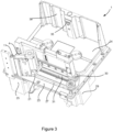
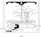
- the tape drive of the printer 1 comprises a linear array of twenty eight radiation emitters 36 and a radiation detector 35 (not all of the emitters are referenced in Figure 4 for clarity). It will be appreciated that any number of emitters 36, including one, may be used.
- the radiation emitters 36 and detector 35 can be used to determine diameter data relating to the supply spool 3 and/or take up spool 5. The operation of the radiation emitters 36 and detector 35 will be described in more detail below.
- the radiation emitters 36 are arranged in a line along a first surface 37 of the tape drive, the first surface 37 extending out of the plane of the back plate 24, and the radiation detector 35 is arranged on a second surface 38, the second surface extending out of the plane of the back plate 24 and being opposite to the first surface 37.
- an intermediary surface such as a mirror
- Placing an intermediary surface, such as a mirror, within the radiation path increases the complexity of the optical sensing system, and increases the chance of a degraded radiation signal being detected by the detector 35.
- material such as dust, may settle on the surface of the mirror, and such material may absorb a portion of, or in extreme cases all of, the radiation.
- the spacing between each of the radiation emitters 36 is not uniform along the length of the array.
- the emitters 36 located towards the middle of the array are spaced further apart than the emitters 36 located towards the edges of the array.
- fewer emitters 36 are required in the middle portion of the array than at the edges of the array in order to determine diameter data.
- equal spacing between each emitter 36 can be used.
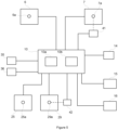
- FIG. 5 is a schematic illustration of components involved in the control of the printer 1.
- the controller 10 comprises a processor 10a and a memory 10b.
- the processor 10a reads instructions from the memory 10b.
- the processor 10a also stores data in and retrieves data from the memory 10b.
- the motors 6, 7, 25, 29 are controlled by control signals generated by the controller 10.
- the controller 10 receives signals from the encoder 41, which signals are indicative of rotational movement of the motor 7.
- the controller also receives signals from the encoder 14, which signals are indicative of linear movement of the substrate 12 past the printer 1.
- the controller 10 also receives signals output from the detector 35 and controls the radiation emitters 36.
- the controller 10 may use signals output by the detector to determine diameter data of one or both of the spools 3, 5, and drive one or more of the motors 6, 7, 25, 29 based on the diameter data.
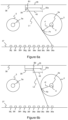
- FIG. 6a to 6d there is described a method of operating a tape drive so as to determine a diameter of a spool. It will be appreciated that Figures 6a to 6d are not to drawn to scale.
- Figure 6a shows a schematic illustration of the tape drive of the printer 1. While only ten radiation emitters 36a-36j are shown, it will be appreciated that any number of emitters 36 may be used, such as 28 as shown in Figure 4 .
- the radiation emitters 36 are LEDs.
- the colour of light emitted by the LEDs may be any suitable colour. For example, the colour may be dependent on characteristics of the detector 35, such as the sensitivity of the detector 35 to particular wavelengths.
- the detector 35 is a charge-coupled device (CCD).
- the detector 35 comprises a detection surface 35a capable of detecting radiation.
- the detection surface 35a comprises an array of discrete pixels, each pixel comprising a photodiode.
- the detection surface 35a may comprises a 128x1 pixel array (e.g. the detector may comprise a TSL1401CL, manufactured by ams AG, of Unterprem Toon, Austria).
- An analogue output from the 128 pixels is passed to an ADC chip (e.g. AD 7278, manufactured by Anaog Devices Inc, of Norwood, Massachusetts).
- the ADC chip may provide a 128-bit serial data output via an SPI interface, each having 8-bits of intensity data per pixel of the sensor.
- the 128 pixels of the detector 35 are aligned parallel to the linear array of emitters 36.
- the controller 10 (not shown in Figures 6a to 6d ) is arranged to energise each emitter 36 in turn and determine diameter data from one or more radiation signals output at the detector 35.
- the controller 10 energises a first emitter 36a to emit radiation.
- a portion of the radiation emitted from the first emitter 36a is incident upon the detection surface 35a of the detector 35 in a first region 39.
- a second region 40 of the detection surface 35a of the detector 35 does not receive radiation directly from the first emitter 36a since the supply spool 3 is partially obscuring the detector 35 from the first emitter 36a. In other words, the supply spool 3 casts a shadow on the detector 35.
- Path L1 illustrates the separation of the portion of the radiation from the first emitter 36a that is directly incident upon the detector 35 and the portion of the radiation which is not directly incident upon the detector 35.
- Path L1 is the tangent at point P1 of the supply spool 3.
- path L1 is a direct radiation path between the emitter 36a and the detector 35, where the path L1 is defined by the spool 3.
- the position at which path L1 intercepts the detection surface 35a of the detector 35 defines a boundary B1 on the detector 35, the boundary B1 separating the first region 39 from the second region 40.
- the detector 35 generates a radiation signal based on the radiation incident on the detection surface 35a. That is, the radiation signal is indicative of path L1.
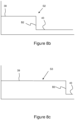
- Figure 8a shows a schematic plot of a radiation signal S1 from the detector 35 when the first emitter 36a is energised, where the y axis corresponds to an intensity of radiation incident on the detection surface 35a and the x axis corresponds to the location along the length of the detection surface 35a (where the location could be pixel location).
- the boundary B1 separates the first region 39 where there is a relatively high intensity of radiation incident on the detector 35 from the second region 40 where there is a relatively low intensity of radiation incident on the detector 35. It will be appreciated that in practice the boundary may span a number of pixels, dependent on the resolution of the detector 35. For example, the intensity of radiation may drop off over about 3 to 5 pixels of the detector 35.
- the controller 10 is configured to determine the location of the boundary B1 based on the radiation signal S1 output from the detector 35.
- the detection surface 35a may comprise a number of pixels, such as 128, and the controller 10 may be configured to determine which pixels directly receive radiation from the radiation output by the first emitter 36a and which pixels do not directly receive radiation from the radiation output by the first emitter 36a. Based on the determination of which pixels directly receive radiation and which pixels do not directly receive radiation, the controller 10 can determine the location of the boundary B1.
- the position of the boundary B1 may be defined in any suitable way.
- the position of the boundary B1 may be defined as the pixel nearest to the average value of the minimum and maximum values of intensity between the boundary B1.
- the position of the boundary B1 may be determined based on a threshold, such as the intensity of radiation being equal to or less than (or greater than) a predetermined value. Interpolation methods may be used on the radiation signal S1 to determine how the radiation signal S1 varies between discrete pixel values of the detector 10.
- the controller 10 may determine the position of the boundary B1 relative to the tape drive 1. The controller 10 may make this determination based on predetermined knowledge, such as the dimensions and/or specification of the detector 35 and the position of the detector 35 within the tape drive.
- the controller 10 can determine data indicative of a diameter of the supply spool 3. For example, a radius r1 of the supply spool 3 can be determined based on the known relative positions of the first emitter 36a, boundary B1, and centre C of the supply spool 3 using trigonometry.
- Figure 9 along with description below, describes in more detail an example method of determining the radius r1 of the supply spool 3.
- the controller 10 may determine the location of the boundary B1 and/or radius r1 after the controller has energised additional radiation emitters 36. For example, the controller 10 may wait to determine boundary B1 and radius r1 after all of the radiation emitters 36 have been energised in turn. Alternatively, the controller 10 may determine the location of the boundary B1 and/or radius r1 prior to energising any further emitters 36.
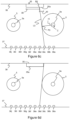
- path L2 which is the tangent at point P2 of the supply spool 3, intercepts the detector 35 to define boundary B2 towards a centre of the detector 35.
- path L2 is a direct radiation path between the second emitter 36b and the detector 35, where the path L2 is defined by the spool 3.
- a radiation signal S2 is generated by the detector 35, a schematic plot of which is shown in Figure 8b . That is, the radiation signal S2 is indicative of path L2.
- the controller 10 determines the position of the boundary B2 and, based on the determination of the position of boundary B2, the controller 10 determines data indicative of the diameter of the supply spool 3, such as radius r2 of the supply spool 3. As above, the controller 10 may determine boundary B2 and radius r2 after the controller has energised all of the radiation emitters 36 in turn. Note that the calculated values of radius r1 and radius r2 may differ slightly. This may be due to measurement error, for example.
- the controller 10 de-energises the second emitter 36b and energises a third emitter 36c to emit radiation.
- path L3 which is the tangent at point P3 of the supply spool 3, intercepts the detector 35 to define boundary B3 towards the left edge (as viewed in Figure 6c ) of the detector 35.
- path L3 is a direct radiation path between the third emitter 36c and the detector 35, where the path L3 is defined by the spool 3.
- a radiation signal S3 is generated by the detector 35, a schematic plot of which is shown in Figure 8c . That is, the radiation signal S3 is indicative of path L3.
- the controller 10 determines the position of the boundary B3, and based on the determination of the position of boundary B3, the controller 10 determines data indicative of the diameter of the supply spool 3, such as radius r3 of the supply spool 3. As above, the controller 10 may determine boundary B3 and radius r3 after the controller has energised all of the radiation emitters 36 in turn.
- the controller de-energises the third emitter 36c and energises a fourth emitter 36d to emit radiation.
- path L4 does not intercept the detector 35. That is, the detection surface 35a of the detector 35 is not in the shadow of the supply spool 3 when the fourth emitter 36d is energised.
- the information provided by the fourth emitter 36d is of limited use in determining an accurate value of the diameter of the supply spool 3.
- the fact that no shadow is cast on detector 35 indicates that the diameter of the supply spool 3 is less than a particular value. That is, the fact that no boundary is present on the detection surface 35a provides information about the diameter of the supply spool 3.
- the controller 10 may continue to energise each of the remaining radiation emitters 36e to 36j in turn. Once all of the radiation emitters 36 have been energised, and the controller has determined radius values r1, r2 and r3 as described above, the controller may then determine the average value of r1, r2 and r3 to arrive at a more accurate determination of the radius of the supply spool 3.
- Using a weighted average which reduces the weight of diameter data determined using a boundary at the edge of the detector also helps avoid any adverse effects caused by step changes when moving between emitters (i.e. as a shadow moves onto, or off, the detector due to increase/decrease in diameter of the spool).
- the controller 10 may determine the diameter data of the supply spool 3 when the supply spool is at eight different angular orientations, separated by 45 degrees.
- the controller 10 may use the diameter data determined at each of the eight angular orientations to determine the diameter of the supply spool 3, such as by determining an average value of the diameter based on the diameter data determined while the supply spool 3 is at each of the angular orientations.
- the controller 10 may, after calibration, select a subset of emitters 36 to energise initially during printing.
- the number of emitters 36 in the subset may remain constant as the subset moves along the array of emitters 36. For example, five emitters 36 may be chosen for the subset, where some or all of the five emitters initially produced a boundary on the detection surface 35a during calibration.
- the controller 10 energises a given emitter 36 and uses the resulting radiation signal output by the detector to determine diameter data.
- the controller 10 is arranged to use multiple radiation signals generated by the same emitter 36 to determine diameter data.
- the controller 10 repeatedly energises and de-energises a given emitter 36 (i.e. flashing the emitter 36 a number of times), to generate a number of radiation signals at the detector 35, before moving on to the next emitter in the array.
- Each of the radiation signals generated for a given emitter 36 can be combined to, for example, reduce the effect of noise and help determine whether a boundary exists in the radiation signals and/or the position of the boundary.
- multiple radiation signals may be recorded for a given emitter 36, and each of these radiation signals can be used to determine a more accurate position of the boundary than if just one radiation signal is used.
- combining each radiation signal for a given emitter can help reduce the effect of random noise in the radiation signal and increase the effect caused by the boundary.
- an image stacking technique may be used to combine the radiation signals for a given emitter 36. Image stacking techniques are well known to the skilled person and so are not described in detail here.
- Background noise may be removed from each radiation signal. This is advantageous in cases where the detector 35 is in a location where there may be a risk of ambient light hitting the detection surface 35. Removing background noise helps the controller 10 to determine the position of the boundary in the radiation signal for a given emitter 36.
- the background noise may be determined a plurality of times.
- the background noise may be determined immediately prior to, or immediately after, an energisation of an emitter 36. That is, prior to, or after, energising an emitter 36, a radiation signal indicative of the background noise (caused by, for example, ambient light incident on the detection surface 35a) may be determined.
- a radiation signal indicative of the background noise (caused by, for example, ambient light incident on the detection surface 35a) may be determined.
- This allows a separate radiation signal indicative of the background noise to be determined for each energisation of a given emitter 36, and hence can be used to remove the background noise for each radiation signal generated during a given energisation of the emitter 36 so as to generate a filtered radiation signal for each energisation of the emitter 36.
- Each of the filtered radiation signals for a given emitter 36 may be combined as described above, such as by using image stacking, to generate a combined filtered radiation signal.
- the combined radiation filtered signal may be used by the controller 10 to determine the position of the boundary on the detector 35 when energising a given emitter 36, and hence determine diameter data indicative of the diameter of the supply spool 3.
- a first background radiation signal may be generated by the detector when a first emitter 36 is not energised so as to determine a first ambient light profile.
- the first emitter 36 is then energised so as to emit radiation and generate a first radiation signal at the detector 35.
- the first background radiation signal may then be subtracted from the first radiation signal to generate a first filtered radiation signal.
- the first emitter 36 is then de-energised and a second background radiation signal is generated to determine a second background ambient light profile.
- the first emitter 36 is then energised to generate a second radiation signal at the detector 35.
- the second background radiation signal may then be subtracted from the second radiation signal to generate a second filtered radiation signal.
- the first and second filtered radiation signals may be summed using, for example, an image stacking method to generate a combined filtered radiation signal for the first emitter 36.
- Figure 9 shows a cross section through the printer
- the above description has described determining the diameter of the supply spool 3 when the supply spool 3 is at a first angular position.
- the method of determining the diameter as described above is carried out at multiple angular positions of the spool 3. For example, once the diameter of the spool has been calculated at the first angular position, the diameter may be recalculated using the above method when the supply spool 3 has travelled through a predetermined angular rotation to a second angular position. For example, a predetermined angular rotation may be 45 degrees.
- data indicative of the eccentricity of the spool 3 can be determined. Determination of eccentricity can be used, for example, to help control advancing of the ribbon during printing.
- the emitters 36 may be used to detect dirt or any other obstruction on the detector 35. For example, all of the emitters 36 may be energised in turn and the determination of a boundary for each of the emitters 36 may be determined as described above. If all of the emitters 36 that are energised create a boundary at around the same location on the detection surface 35a of the detector 35, it can be determined that there is dirt on the detection surface 35a. This is because boundaries formed by the shadow cast by a spool will be in different positions on the detector 35 dependent on the position of the energised emitter 36.
- the detection of dirt may be determined using the method described above, where emitters 36 are energised multiple times, the background removed, and each filtered radiation signal combined. The detection of dirt may be carried out at any time, i.e. prior to, during, or after printing. An alert signal may be generated if dirt is detected so as to warn a user that dirt is present.
- the tape drive may comprise multiple detectors.
- multiple detectors may be used with a single emitter (or multiple emitters).
- the multiple detectors may be arranged in an array in a similar manner to the emitters shown in Figure 4 .
- the shadow cast by an emitter 36 will block radiation from reaching some of the detectors of the array, but will not prevent radiation hitting others of the detectors of the array.
Landscapes
- Impression-Transfer Materials And Handling Thereof (AREA)
- Electronic Switches (AREA)
Claims (15)
- Bandantrieb, umfassend:einen ersten und einen zweiten Spulenträger (3a, 5a), auf denen Bandspulen (3, 5) angebracht werden können,ein optisches Abtastsystem, das einen Strahlungsemitter (36) und einen Strahlungsdetektor (35) umfasst, wobei der Strahlungsemitter und der Strahlungsdetektor im Gebrauch eine feste Positionsbeziehung in Bezug auf die beiden Bandspulenträger haben,eine Steuerungseinrichtung, die dafür betreibbar ist:den Strahlungssender mit Energie zu versorgen, damit er Strahlung emittiert; undDurchmesserdaten, die einen Durchmesser einer auf einem des ersten und des zweiten Spulenträgers angebrachten Spule kennzeichnen, auf der Grundlage eines durch den Detektor erzeugten Strahlungssignals zu bestimmen, wobei das Strahlungssignal einen direkten Strahlungsweg (L1, L2, L3) zwischen dem Emitter und dem Detektor kennzeichnet, wobei der Strahlungsweg durch die Spule definiert ist, wobei die Steuerungseinrichtung ferner dafür betreibbar ist, die Durchmesserdaten zu bestimmen, wenn die Bandspule sich an einer Vielzahl von Winkelpositionen befindet, um Durchmesserdaten für jede der Winkelpositionen zu erlangen, und auf der Grundlage der für jede der Winkelpositionen erlangten Durchmesserdaten einen Durchschnittswert der Durchmesserdaten zu bestimmen.
- Bandantrieb nach Anspruch 1, wobei die Steuerungseinrichtung ferner dafür betreibbar ist, die Durchmesserdaten auf der Grundlage von vorbestimmten Positionsdaten zu bestimmen, die sich auf das optische Abtastsystem beziehen.
- Bandantrieb nach Anspruch 1 oder 2, wobei die Steuerungseinrichtung ferner dafür betreibbar ist, die Durchmesserdaten auf der Grundlage vorbestimmter Positionsdaten zu bestimmen, die sich auf einen des ersten oder des zweiten Spulenträgers (3a, 5a) beziehen.
- Bandantrieb nach Anspruch 1 bis 3, wobei das optische Abtastsystem ferner eine Vielzahl von Strahlungsemittern (36) umfasst und wobei die Steuerungseinrichtung ferner dafür betreibbar ist:die Vielzahl von Strahlungsemittern mit Energie zu versorgen, damit jeder Strahlung emittiert;Durchmesserdaten, die einen Durchmesser einer auf einem des ersten und des zweiten Spulenträgers (3a, 5a) angebrachten Spule (3, 5) kennzeichnen, auf der Grundlage einer Vielzahl von durch den Detektor (35) erzeugten Strahlungssignals zu bestimmen, wobei die Vielzahl von Strahlungssignalen zwei oder mehr direkte Strahlungswege (L1, L2, L3) zwischen den Emittern und dem Detektor angibt, wobei die Strahlungswege durch die Spule definiert sind.
- Bandantrieb nach einem der vorhergehenden Ansprüche, wobei die Steuerungseinrichtung ferner dafür betreibbar ist:ein Merkmal des einen oder der mehreren Strahlungssignale zu bestimmen, undfür jedes des einen oder der mehreren Strahlungssignale Durchmesserdaten zu bestimmen, die den Durchmesser der Spule (3, 5) angeben, und zwar auf der Grundlage des jeweiligen Merkmals des einen oder der mehreren Strahlungssignale.
- Bandantrieb nach Anspruch 5, wobei das Merkmal aus Positionsdaten besteht, die sich auf das eine oder die mehreren Strahlungssignale beziehen, und optional, wobei die Positionsdaten Daten umfassen, die sich auf eine Grenze (B1, B2, B3) beziehen, wobei die Grenze einen ersten Bereich des Detektors von einem zweiten Bereich des Detektors trennt, wobei der erste Bereich einem Bereich entspricht, der einen ersten Strahlungspegel von einem Emitter (36) empfängt, und der zweite Bereich einem Bereich entspricht, der einen zweiten Strahlungspegel von dem Emitter empfängt.
- Bandantrieb nach Anspruch 5 bis 6, wobei die Steuerungseinrichtung ferner dafür betreibbar ist, einen zweiten Durchschnittswert der Durchmesserdaten zu bestimmen, der den Durchmesser der Spule angibt, wenn die Spule sich in einer Winkelposition der Vielzahl von Winkelpositionen befindet, wobei der zweite Durchschnittswert auf jedem der Durchmesserdaten beruht, die unter Verwendung jedes des einen oder der mehreren Strahlungssignale erzeugt wurden.
- Bandantrieb nach Anspruch 7, wobei die Steuerungseinrichtung ferner dafür betreibbar ist, einen Wichtungsfaktor auf jeden der Durchmesserdaten anzuwenden, die unter Verwendung von jedem des einen oder der mehreren Strahlungssignale erzeugt werden.
- Bandantrieb nach Anspruch 8, wobei der auf die einzelnen Durchmesserdaten angewendete Wichtungsfaktor von dem Merkmal des jeweiligen Strahlungssignals abhängt.
- Bandantrieb nach einem der Ansprüche 5 bis 9, wobei die Steuerungseinrichtung ferner dafür betreibbar ist:einen oder mehrere der Vielzahl der Strahlungsemitter (36) mit Energie zu versorgen, sodass jeder des einen oder der mehreren der Vielzahl von Strahlungsemittern eine Vielzahl von Malen Strahlung aussendet; undeine Vielzahl von Strahlungssignalen, die durch den Detektor (35) für einen gegebenen Emitter erzeugt wird, zu verwenden, um das Merkmal des Strahlungssignals zu bestimmen.
- Bandantrieb nach Anspruch 10, wobei die Steuerungseinrichtung ferner dafür betreibbar ist:
von jedem der Vielzahl von Strahlungssignalen, die durch den Detektor für einen gegebenen Emitter (36) erzeugt werden, ein Hintergrundrauschsignal zu subtrahieren, um für den gegebenen Emitter eine Vielzahl von gefilterten Signalen zu erlangen, und das Merkmal des Strahlungssignals unter Verwendung der Vielzahl von gefilterten Strahlungssignalen für den gegebenen Emitter zu bestimmen. - Bandantrieb nach Anspruch 11, wobei die Steuerungseinrichtung ferner dafür betreibbar ist:eine Vielzahl von Hintergrundrauschsignalen zu bestimmen, wobei jedes der Hintergrundrauschsignale vor oder nach der Ermittlung von jedem der Vielzahl von Strahlungssignalen für den gegebenen Emitter (36) bestimmt wird, undjedes jeweilige der Hintergrundrauschsignale von jedem jeweiligen der Vielzahl von Strahlungssignalen für den gegebenen Emitter zu subtrahieren.
- Bandantrieb nach einem der vorhergehenden Ansprüche, wobei die Steuerungseinrichtung ferner dafür betreibbar ist, eine Exzentrizität der Bandspule (3, 5) unter Verwendung der Durchmesserdaten für jede der Winkelpositionen zu bestimmen.
- Verfahren zur Verwendung eines Bandantriebs nach einem der vorhergehenden Ansprüche, um ein Durchmesserdatenelement zu bestimmen, das einen Durchmesser einer Bandspule (3, 5) angibt.
- Thermotransferdrucker (1), umfassend:einen Bandantrieb nach einem der Ansprüche 1 bis 13, der dafür eingerichtet ist, tintenführendes Band (2) zwischen der ersten und der zweiten Spule (3, 5) zu übertragen; undeinen Druckkopf (4), der dafür eingerichtet ist, Tinte von dem tintenführenden Band auf ein Substrat zu übertragen.
Applications Claiming Priority (2)
| Application Number | Priority Date | Filing Date | Title |
|---|---|---|---|
| GBGB1710391.2A GB201710391D0 (en) | 2017-06-29 | 2017-06-29 | Tape drive |
| PCT/GB2018/051837 WO2019002886A1 (en) | 2017-06-29 | 2018-06-29 | BAND DRIVING DEVICE |
Publications (2)
| Publication Number | Publication Date |
|---|---|
| EP3645293A1 EP3645293A1 (de) | 2020-05-06 |
| EP3645293B1 true EP3645293B1 (de) | 2023-07-12 |
Family
ID=59592458
Family Applications (1)
| Application Number | Title | Priority Date | Filing Date |
|---|---|---|---|
| EP18739613.0A Active EP3645293B1 (de) | 2017-06-29 | 2018-06-29 | Bandantrieb |
Country Status (5)
| Country | Link |
|---|---|
| US (1) | US11745528B2 (de) |
| EP (1) | EP3645293B1 (de) |
| CN (1) | CN110869220B (de) |
| GB (1) | GB201710391D0 (de) |
| WO (1) | WO2019002886A1 (de) |
Family Cites Families (16)
| Publication number | Priority date | Publication date | Assignee | Title |
|---|---|---|---|---|
| US3980890A (en) * | 1975-03-19 | 1976-09-14 | Presto Products, Incorporated | Optical thickness detecting and comparing method and apparatus |
| US4115013A (en) * | 1977-03-30 | 1978-09-19 | Xerox Corporation | End-of-ribbon sensor device |
| US4636097A (en) * | 1980-05-20 | 1987-01-13 | Monarch Marking Systems, Inc. | Replaceable inking cartridge with depletion counter |
| SE425126B (sv) | 1981-08-26 | 1982-08-30 | Kockumation Ab | Forfarande for indikering av ett foremals nervaro i en metzon och anordning for genomforande av forfarandet |
| JPH0222090A (ja) * | 1988-07-12 | 1990-01-24 | Matsushita Electric Ind Co Ltd | 印字装置 |
| JPH10244724A (ja) | 1997-03-06 | 1998-09-14 | Oki Electric Ind Co Ltd | インクリボン巻取装置と券処理装置 |
| US5820280A (en) | 1997-08-28 | 1998-10-13 | Intermec Corporation | Printer with variable torque distribution |
| EP2298567B1 (de) * | 2000-09-11 | 2015-07-22 | Videojet Technologies, Inc. | Wärmeübertragungsdrucker mit Bandlaufwerk und Steuerungsverfahren dafür |
| GB0123303D0 (en) | 2001-09-28 | 2001-11-21 | Zipher Ltd | Tape drive |
| US6989180B2 (en) * | 2003-10-09 | 2006-01-24 | Ncr Corporation | Thermal transfer ribbon with end of ribbon markers |
| SE0401049L (sv) | 2004-04-29 | 2005-07-26 | Mindproxy Ab | Metod och anordning för att mäta ett objekts utsträckning |
| EP2744665B2 (de) * | 2011-08-15 | 2024-12-04 | Videojet Technologies Inc. | Thermotransferdrucker |
| US8801141B2 (en) * | 2012-04-27 | 2014-08-12 | Canon Kabushiki Kaisha | Recording apparatus, detection method, and storage medium |
| JP2014128947A (ja) | 2012-12-28 | 2014-07-10 | Nisca Corp | リボン残量検知機構及び印刷装置 |
| JP2015063077A (ja) | 2013-09-25 | 2015-04-09 | ニスカ株式会社 | 印刷装置およびインクリボンカセット |
| CN106382892B (zh) | 2016-08-19 | 2019-08-06 | 广东省智能制造研究所 | 一种基于三角函数测量收放带系统卷带卷径的方法及装置 |
-
2017
- 2017-06-29 GB GBGB1710391.2A patent/GB201710391D0/en not_active Ceased
-
2018
- 2018-06-29 WO PCT/GB2018/051837 patent/WO2019002886A1/en not_active Ceased
- 2018-06-29 US US16/624,594 patent/US11745528B2/en active Active
- 2018-06-29 CN CN201880044237.6A patent/CN110869220B/zh active Active
- 2018-06-29 EP EP18739613.0A patent/EP3645293B1/de active Active
Also Published As
| Publication number | Publication date |
|---|---|
| EP3645293A1 (de) | 2020-05-06 |
| CN110869220B (zh) | 2022-04-01 |
| GB201710391D0 (en) | 2017-08-16 |
| CN110869220A (zh) | 2020-03-06 |
| WO2019002886A1 (en) | 2019-01-03 |
| US20200114671A1 (en) | 2020-04-16 |
| US11745528B2 (en) | 2023-09-05 |
Similar Documents
| Publication | Publication Date | Title |
|---|---|---|
| CN111886475B (zh) | 片材厚度测量装置 | |
| US20120240803A1 (en) | Image-forming device and method for forming an image | |
| US11919320B2 (en) | Transfer printer and method | |
| US9976899B2 (en) | Spectroscopic measurement device, image forming apparatus, and spectroscopic measurement method | |
| US10788814B2 (en) | Encoder, robot, and printer | |
| JP2000185855A (ja) | 帯状素材の摩擦駆動装置、エッジ検知装置、及び自動アライン方法 | |
| US20050150747A1 (en) | Belt tracking | |
| JP6339970B2 (ja) | 移動手摺り劣化診断装置 | |
| JP2015059027A (ja) | 搬送装置、画像記録装置、および検出方法 | |
| US8724118B1 (en) | Mobile apparatus with local position referencing structure | |
| US11745528B2 (en) | Tape drive | |
| US9010924B2 (en) | System and method for aligning duplex images using alignment marks | |
| US20140144376A1 (en) | Mobile apparatus with local position referencing elements | |
| US20050024415A1 (en) | Media-position sensor system | |
| JP2005249452A (ja) | リニアエンコーダ、画像読取装置及び画像記録装置 | |
| US9046346B2 (en) | Determining a position of a mobile apparatus | |
| JP2011042088A (ja) | プリンタ及びプリンタの制御方法 | |
| JP6820221B2 (ja) | 巻取り装置 | |
| EP3020667B1 (de) | Transportvorrichtung und aufzeichnungsvorrichtung | |
| JPH11334170A (ja) | 運動部材の移動位置検出装置 | |
| JP2021134073A (ja) | ベルト駆動装置および画像形成装置 | |
| JP5622861B2 (ja) | 印刷システム内の物体の速度を決定するための方法 | |
| EP3776077B1 (de) | Steuereinheit und zugehöriges verfahren für filmtransportvorrichtung | |
| JPS63277916A (ja) | 帯状物体の反り量計測装置 | |
| CN114080322A (zh) | 印刷装置及印刷方法 |
Legal Events
| Date | Code | Title | Description |
|---|---|---|---|
| STAA | Information on the status of an ep patent application or granted ep patent |
Free format text: STATUS: UNKNOWN |
|
| STAA | Information on the status of an ep patent application or granted ep patent |
Free format text: STATUS: THE INTERNATIONAL PUBLICATION HAS BEEN MADE |
|
| PUAI | Public reference made under article 153(3) epc to a published international application that has entered the european phase |
Free format text: ORIGINAL CODE: 0009012 |
|
| STAA | Information on the status of an ep patent application or granted ep patent |
Free format text: STATUS: REQUEST FOR EXAMINATION WAS MADE |
|
| 17P | Request for examination filed |
Effective date: 20191219 |
|
| AK | Designated contracting states |
Kind code of ref document: A1 Designated state(s): AL AT BE BG CH CY CZ DE DK EE ES FI FR GB GR HR HU IE IS IT LI LT LU LV MC MK MT NL NO PL PT RO RS SE SI SK SM TR |
|
| AX | Request for extension of the european patent |
Extension state: BA ME |
|
| DAV | Request for validation of the european patent (deleted) | ||
| DAX | Request for extension of the european patent (deleted) | ||
| GRAP | Despatch of communication of intention to grant a patent |
Free format text: ORIGINAL CODE: EPIDOSNIGR1 |
|
| STAA | Information on the status of an ep patent application or granted ep patent |
Free format text: STATUS: GRANT OF PATENT IS INTENDED |
|
| INTG | Intention to grant announced |
Effective date: 20220127 |
|
| GRAJ | Information related to disapproval of communication of intention to grant by the applicant or resumption of examination proceedings by the epo deleted |
Free format text: ORIGINAL CODE: EPIDOSDIGR1 |
|
| STAA | Information on the status of an ep patent application or granted ep patent |
Free format text: STATUS: REQUEST FOR EXAMINATION WAS MADE |
|
| INTC | Intention to grant announced (deleted) | ||
| GRAP | Despatch of communication of intention to grant a patent |
Free format text: ORIGINAL CODE: EPIDOSNIGR1 |
|
| STAA | Information on the status of an ep patent application or granted ep patent |
Free format text: STATUS: GRANT OF PATENT IS INTENDED |
|
| INTG | Intention to grant announced |
Effective date: 20220810 |
|
| GRAJ | Information related to disapproval of communication of intention to grant by the applicant or resumption of examination proceedings by the epo deleted |
Free format text: ORIGINAL CODE: EPIDOSDIGR1 |
|
| STAA | Information on the status of an ep patent application or granted ep patent |
Free format text: STATUS: REQUEST FOR EXAMINATION WAS MADE |
|
| INTC | Intention to grant announced (deleted) | ||
| GRAP | Despatch of communication of intention to grant a patent |
Free format text: ORIGINAL CODE: EPIDOSNIGR1 |
|
| STAA | Information on the status of an ep patent application or granted ep patent |
Free format text: STATUS: GRANT OF PATENT IS INTENDED |
|
| INTG | Intention to grant announced |
Effective date: 20230127 |
|
| GRAS | Grant fee paid |
Free format text: ORIGINAL CODE: EPIDOSNIGR3 |
|
| GRAA | (expected) grant |
Free format text: ORIGINAL CODE: 0009210 |
|
| STAA | Information on the status of an ep patent application or granted ep patent |
Free format text: STATUS: THE PATENT HAS BEEN GRANTED |
|
| AK | Designated contracting states |
Kind code of ref document: B1 Designated state(s): AL AT BE BG CH CY CZ DE DK EE ES FI FR GB GR HR HU IE IS IT LI LT LU LV MC MK MT NL NO PL PT RO RS SE SI SK SM TR |
|
| P01 | Opt-out of the competence of the unified patent court (upc) registered |
Effective date: 20230530 |
|
| REG | Reference to a national code |
Ref country code: CH Ref legal event code: EP |
|
| REG | Reference to a national code |
Ref country code: DE Ref legal event code: R096 Ref document number: 602018053201 Country of ref document: DE |
|
| REG | Reference to a national code |
Ref country code: IE Ref legal event code: FG4D |
|
| REG | Reference to a national code |
Ref country code: LT Ref legal event code: MG9D |
|
| REG | Reference to a national code |
Ref country code: NL Ref legal event code: MP Effective date: 20230712 |
|
| REG | Reference to a national code |
Ref country code: AT Ref legal event code: MK05 Ref document number: 1586737 Country of ref document: AT Kind code of ref document: T Effective date: 20230712 |
|
| PG25 | Lapsed in a contracting state [announced via postgrant information from national office to epo] |
Ref country code: NL Free format text: LAPSE BECAUSE OF FAILURE TO SUBMIT A TRANSLATION OF THE DESCRIPTION OR TO PAY THE FEE WITHIN THE PRESCRIBED TIME-LIMIT Effective date: 20230712 |
|
| PG25 | Lapsed in a contracting state [announced via postgrant information from national office to epo] |
Ref country code: GR Free format text: LAPSE BECAUSE OF FAILURE TO SUBMIT A TRANSLATION OF THE DESCRIPTION OR TO PAY THE FEE WITHIN THE PRESCRIBED TIME-LIMIT Effective date: 20231013 |
|
| PG25 | Lapsed in a contracting state [announced via postgrant information from national office to epo] |
Ref country code: ES Free format text: LAPSE BECAUSE OF FAILURE TO SUBMIT A TRANSLATION OF THE DESCRIPTION OR TO PAY THE FEE WITHIN THE PRESCRIBED TIME-LIMIT Effective date: 20230712 |
|
| PG25 | Lapsed in a contracting state [announced via postgrant information from national office to epo] |
Ref country code: IS Free format text: LAPSE BECAUSE OF FAILURE TO SUBMIT A TRANSLATION OF THE DESCRIPTION OR TO PAY THE FEE WITHIN THE PRESCRIBED TIME-LIMIT Effective date: 20231112 |
|
| PG25 | Lapsed in a contracting state [announced via postgrant information from national office to epo] |
Ref country code: SE Free format text: LAPSE BECAUSE OF FAILURE TO SUBMIT A TRANSLATION OF THE DESCRIPTION OR TO PAY THE FEE WITHIN THE PRESCRIBED TIME-LIMIT Effective date: 20230712 Ref country code: RS Free format text: LAPSE BECAUSE OF FAILURE TO SUBMIT A TRANSLATION OF THE DESCRIPTION OR TO PAY THE FEE WITHIN THE PRESCRIBED TIME-LIMIT Effective date: 20230712 Ref country code: PT Free format text: LAPSE BECAUSE OF FAILURE TO SUBMIT A TRANSLATION OF THE DESCRIPTION OR TO PAY THE FEE WITHIN THE PRESCRIBED TIME-LIMIT Effective date: 20231113 Ref country code: NO Free format text: LAPSE BECAUSE OF FAILURE TO SUBMIT A TRANSLATION OF THE DESCRIPTION OR TO PAY THE FEE WITHIN THE PRESCRIBED TIME-LIMIT Effective date: 20231012 Ref country code: LV Free format text: LAPSE BECAUSE OF FAILURE TO SUBMIT A TRANSLATION OF THE DESCRIPTION OR TO PAY THE FEE WITHIN THE PRESCRIBED TIME-LIMIT Effective date: 20230712 Ref country code: LT Free format text: LAPSE BECAUSE OF FAILURE TO SUBMIT A TRANSLATION OF THE DESCRIPTION OR TO PAY THE FEE WITHIN THE PRESCRIBED TIME-LIMIT Effective date: 20230712 Ref country code: IS Free format text: LAPSE BECAUSE OF FAILURE TO SUBMIT A TRANSLATION OF THE DESCRIPTION OR TO PAY THE FEE WITHIN THE PRESCRIBED TIME-LIMIT Effective date: 20231112 Ref country code: HR Free format text: LAPSE BECAUSE OF FAILURE TO SUBMIT A TRANSLATION OF THE DESCRIPTION OR TO PAY THE FEE WITHIN THE PRESCRIBED TIME-LIMIT Effective date: 20230712 Ref country code: GR Free format text: LAPSE BECAUSE OF FAILURE TO SUBMIT A TRANSLATION OF THE DESCRIPTION OR TO PAY THE FEE WITHIN THE PRESCRIBED TIME-LIMIT Effective date: 20231013 Ref country code: FI Free format text: LAPSE BECAUSE OF FAILURE TO SUBMIT A TRANSLATION OF THE DESCRIPTION OR TO PAY THE FEE WITHIN THE PRESCRIBED TIME-LIMIT Effective date: 20230712 Ref country code: ES Free format text: LAPSE BECAUSE OF FAILURE TO SUBMIT A TRANSLATION OF THE DESCRIPTION OR TO PAY THE FEE WITHIN THE PRESCRIBED TIME-LIMIT Effective date: 20230712 Ref country code: AT Free format text: LAPSE BECAUSE OF FAILURE TO SUBMIT A TRANSLATION OF THE DESCRIPTION OR TO PAY THE FEE WITHIN THE PRESCRIBED TIME-LIMIT Effective date: 20230712 |
|
| PG25 | Lapsed in a contracting state [announced via postgrant information from national office to epo] |
Ref country code: PL Free format text: LAPSE BECAUSE OF FAILURE TO SUBMIT A TRANSLATION OF THE DESCRIPTION OR TO PAY THE FEE WITHIN THE PRESCRIBED TIME-LIMIT Effective date: 20230712 |
|
| REG | Reference to a national code |
Ref country code: DE Ref legal event code: R097 Ref document number: 602018053201 Country of ref document: DE |
|
| PG25 | Lapsed in a contracting state [announced via postgrant information from national office to epo] |
Ref country code: SM Free format text: LAPSE BECAUSE OF FAILURE TO SUBMIT A TRANSLATION OF THE DESCRIPTION OR TO PAY THE FEE WITHIN THE PRESCRIBED TIME-LIMIT Effective date: 20230712 Ref country code: RO Free format text: LAPSE BECAUSE OF FAILURE TO SUBMIT A TRANSLATION OF THE DESCRIPTION OR TO PAY THE FEE WITHIN THE PRESCRIBED TIME-LIMIT Effective date: 20230712 Ref country code: EE Free format text: LAPSE BECAUSE OF FAILURE TO SUBMIT A TRANSLATION OF THE DESCRIPTION OR TO PAY THE FEE WITHIN THE PRESCRIBED TIME-LIMIT Effective date: 20230712 Ref country code: DK Free format text: LAPSE BECAUSE OF FAILURE TO SUBMIT A TRANSLATION OF THE DESCRIPTION OR TO PAY THE FEE WITHIN THE PRESCRIBED TIME-LIMIT Effective date: 20230712 Ref country code: CZ Free format text: LAPSE BECAUSE OF FAILURE TO SUBMIT A TRANSLATION OF THE DESCRIPTION OR TO PAY THE FEE WITHIN THE PRESCRIBED TIME-LIMIT Effective date: 20230712 Ref country code: SK Free format text: LAPSE BECAUSE OF FAILURE TO SUBMIT A TRANSLATION OF THE DESCRIPTION OR TO PAY THE FEE WITHIN THE PRESCRIBED TIME-LIMIT Effective date: 20230712 |
|
| PLBE | No opposition filed within time limit |
Free format text: ORIGINAL CODE: 0009261 |
|
| STAA | Information on the status of an ep patent application or granted ep patent |
Free format text: STATUS: NO OPPOSITION FILED WITHIN TIME LIMIT |
|
| PG25 | Lapsed in a contracting state [announced via postgrant information from national office to epo] |
Ref country code: IT Free format text: LAPSE BECAUSE OF FAILURE TO SUBMIT A TRANSLATION OF THE DESCRIPTION OR TO PAY THE FEE WITHIN THE PRESCRIBED TIME-LIMIT Effective date: 20230712 |
|
| 26N | No opposition filed |
Effective date: 20240415 |
|
| PG25 | Lapsed in a contracting state [announced via postgrant information from national office to epo] |
Ref country code: SI Free format text: LAPSE BECAUSE OF FAILURE TO SUBMIT A TRANSLATION OF THE DESCRIPTION OR TO PAY THE FEE WITHIN THE PRESCRIBED TIME-LIMIT Effective date: 20230712 |
|
| PG25 | Lapsed in a contracting state [announced via postgrant information from national office to epo] |
Ref country code: BG Free format text: LAPSE BECAUSE OF FAILURE TO SUBMIT A TRANSLATION OF THE DESCRIPTION OR TO PAY THE FEE WITHIN THE PRESCRIBED TIME-LIMIT Effective date: 20230712 |
|
| PG25 | Lapsed in a contracting state [announced via postgrant information from national office to epo] |
Ref country code: BG Free format text: LAPSE BECAUSE OF FAILURE TO SUBMIT A TRANSLATION OF THE DESCRIPTION OR TO PAY THE FEE WITHIN THE PRESCRIBED TIME-LIMIT Effective date: 20230712 |
|
| PG25 | Lapsed in a contracting state [announced via postgrant information from national office to epo] |
Ref country code: MC Free format text: LAPSE BECAUSE OF FAILURE TO SUBMIT A TRANSLATION OF THE DESCRIPTION OR TO PAY THE FEE WITHIN THE PRESCRIBED TIME-LIMIT Effective date: 20230712 |
|
| REG | Reference to a national code |
Ref country code: CH Ref legal event code: PL |
|
| PG25 | Lapsed in a contracting state [announced via postgrant information from national office to epo] |
Ref country code: LU Free format text: LAPSE BECAUSE OF NON-PAYMENT OF DUE FEES Effective date: 20240629 |
|
| PG25 | Lapsed in a contracting state [announced via postgrant information from national office to epo] |
Ref country code: IE Free format text: LAPSE BECAUSE OF NON-PAYMENT OF DUE FEES Effective date: 20240629 |
|
| PG25 | Lapsed in a contracting state [announced via postgrant information from national office to epo] |
Ref country code: BE Free format text: LAPSE BECAUSE OF NON-PAYMENT OF DUE FEES Effective date: 20240630 Ref country code: CH Free format text: LAPSE BECAUSE OF NON-PAYMENT OF DUE FEES Effective date: 20240630 |
|
| REG | Reference to a national code |
Ref country code: BE Ref legal event code: MM Effective date: 20240630 |
|
| PGFP | Annual fee paid to national office [announced via postgrant information from national office to epo] |
Ref country code: DE Payment date: 20250618 Year of fee payment: 8 |
|
| PGFP | Annual fee paid to national office [announced via postgrant information from national office to epo] |
Ref country code: GB Payment date: 20250618 Year of fee payment: 8 |
|
| PGFP | Annual fee paid to national office [announced via postgrant information from national office to epo] |
Ref country code: FR Payment date: 20250626 Year of fee payment: 8 |
|
| PG25 | Lapsed in a contracting state [announced via postgrant information from national office to epo] |
Ref country code: CY Free format text: LAPSE BECAUSE OF FAILURE TO SUBMIT A TRANSLATION OF THE DESCRIPTION OR TO PAY THE FEE WITHIN THE PRESCRIBED TIME-LIMIT; INVALID AB INITIO Effective date: 20180629 |
|
| PG25 | Lapsed in a contracting state [announced via postgrant information from national office to epo] |
Ref country code: HU Free format text: LAPSE BECAUSE OF FAILURE TO SUBMIT A TRANSLATION OF THE DESCRIPTION OR TO PAY THE FEE WITHIN THE PRESCRIBED TIME-LIMIT; INVALID AB INITIO Effective date: 20180629 |