EP3643495B1 - Article having water- and oil-repellent layer formed thereon, and method for manufacturing same - Google Patents
Article having water- and oil-repellent layer formed thereon, and method for manufacturing same Download PDFInfo
- Publication number
- EP3643495B1 EP3643495B1 EP18819594.5A EP18819594A EP3643495B1 EP 3643495 B1 EP3643495 B1 EP 3643495B1 EP 18819594 A EP18819594 A EP 18819594A EP 3643495 B1 EP3643495 B1 EP 3643495B1
- Authority
- EP
- European Patent Office
- Prior art keywords
- silicon oxide
- water
- oxide layer
- alkali metal
- oil repellent
- Prior art date
- Legal status (The legal status is an assumption and is not a legal conclusion. Google has not performed a legal analysis and makes no representation as to the accuracy of the status listed.)
- Active
Links
- 239000005871 repellent Substances 0.000 title claims description 174
- 238000000034 method Methods 0.000 title claims description 44
- 238000004519 manufacturing process Methods 0.000 title claims description 37
- VYPSYNLAJGMNEJ-UHFFFAOYSA-N Silicium dioxide Chemical compound O=[Si]=O VYPSYNLAJGMNEJ-UHFFFAOYSA-N 0.000 claims description 260
- 229910052814 silicon oxide Inorganic materials 0.000 claims description 225
- XLYOFNOQVPJJNP-UHFFFAOYSA-N water Substances O XLYOFNOQVPJJNP-UHFFFAOYSA-N 0.000 claims description 214
- 239000003921 oil Substances 0.000 claims description 182
- 230000002940 repellent Effects 0.000 claims description 173
- 150000001340 alkali metals Chemical group 0.000 claims description 106
- 150000001875 compounds Chemical class 0.000 claims description 87
- 239000000758 substrate Substances 0.000 claims description 85
- 238000000576 coating method Methods 0.000 claims description 51
- 229910052783 alkali metal Inorganic materials 0.000 claims description 48
- 125000003808 silyl group Chemical group [H][Si]([H])([H])[*] 0.000 claims description 44
- 125000004429 atom Chemical group 0.000 claims description 38
- 239000011248 coating agent Substances 0.000 claims description 38
- 235000012239 silicon dioxide Nutrition 0.000 claims description 38
- RMAQACBXLXPBSY-UHFFFAOYSA-N silicic acid Chemical compound O[Si](O)(O)O RMAQACBXLXPBSY-UHFFFAOYSA-N 0.000 claims description 31
- 239000012530 fluid Substances 0.000 claims description 26
- 238000011282 treatment Methods 0.000 claims description 19
- 238000000151 deposition Methods 0.000 claims description 17
- 239000002904 solvent Substances 0.000 claims description 15
- 238000003851 corona treatment Methods 0.000 claims description 13
- 239000002243 precursor Substances 0.000 claims description 11
- XUIMIQQOPSSXEZ-UHFFFAOYSA-N Silicon Chemical compound [Si] XUIMIQQOPSSXEZ-UHFFFAOYSA-N 0.000 claims description 9
- 239000000463 material Substances 0.000 claims description 7
- 229910052710 silicon Inorganic materials 0.000 claims description 7
- 125000004436 sodium atom Chemical group 0.000 claims description 7
- 239000010703 silicon Substances 0.000 claims description 4
- 238000010559 graft polymerization reaction Methods 0.000 claims description 3
- 238000009832 plasma treatment Methods 0.000 claims description 3
- HEMHJVSKTPXQMS-UHFFFAOYSA-M Sodium hydroxide Chemical compound [OH-].[Na+] HEMHJVSKTPXQMS-UHFFFAOYSA-M 0.000 description 93
- 239000011734 sodium Substances 0.000 description 59
- 238000005299 abrasion Methods 0.000 description 58
- 229910052708 sodium Inorganic materials 0.000 description 49
- DGAQECJNVWCQMB-PUAWFVPOSA-M Ilexoside XXIX Chemical compound C[C@@H]1CC[C@@]2(CC[C@@]3(C(=CC[C@H]4[C@]3(CC[C@@H]5[C@@]4(CC[C@@H](C5(C)C)OS(=O)(=O)[O-])C)C)[C@@H]2[C@]1(C)O)C)C(=O)O[C@H]6[C@@H]([C@H]([C@@H]([C@H](O6)CO)O)O)O.[Na+] DGAQECJNVWCQMB-PUAWFVPOSA-M 0.000 description 48
- 125000004432 carbon atom Chemical group C* 0.000 description 31
- 239000000047 product Substances 0.000 description 26
- 239000000243 solution Substances 0.000 description 23
- 238000005011 time of flight secondary ion mass spectroscopy Methods 0.000 description 23
- 238000002042 time-of-flight secondary ion mass spectrometry Methods 0.000 description 23
- 239000003960 organic solvent Substances 0.000 description 22
- 125000004435 hydrogen atom Chemical group [H]* 0.000 description 20
- 125000004430 oxygen atom Chemical group O* 0.000 description 20
- -1 fluorinated ether compound Chemical class 0.000 description 18
- 150000002500 ions Chemical class 0.000 description 18
- 239000011521 glass Substances 0.000 description 17
- 238000004544 sputter deposition Methods 0.000 description 17
- KWYUFKZDYYNOTN-UHFFFAOYSA-M Potassium hydroxide Chemical compound [OH-].[K+] KWYUFKZDYYNOTN-UHFFFAOYSA-M 0.000 description 15
- 230000008021 deposition Effects 0.000 description 15
- 239000010408 film Substances 0.000 description 14
- 238000001771 vacuum deposition Methods 0.000 description 14
- 125000005010 perfluoroalkyl group Chemical group 0.000 description 13
- CDBYLPFSWZWCQE-UHFFFAOYSA-L Sodium Carbonate Chemical compound [Na+].[Na+].[O-]C([O-])=O CDBYLPFSWZWCQE-UHFFFAOYSA-L 0.000 description 12
- 239000000377 silicon dioxide Substances 0.000 description 12
- WMFOQBRAJBCJND-UHFFFAOYSA-M Lithium hydroxide Chemical compound [Li+].[OH-] WMFOQBRAJBCJND-UHFFFAOYSA-M 0.000 description 11
- 229910052910 alkali metal silicate Inorganic materials 0.000 description 11
- 229910052700 potassium Inorganic materials 0.000 description 11
- 125000005372 silanol group Chemical group 0.000 description 11
- 238000010304 firing Methods 0.000 description 10
- 125000006551 perfluoro alkylene group Chemical group 0.000 description 10
- 239000000843 powder Substances 0.000 description 10
- KFZMGEQAYNKOFK-UHFFFAOYSA-N Isopropanol Chemical compound CC(C)O KFZMGEQAYNKOFK-UHFFFAOYSA-N 0.000 description 9
- 239000000499 gel Substances 0.000 description 9
- 239000000523 sample Substances 0.000 description 9
- 229910002027 silica gel Inorganic materials 0.000 description 9
- 239000000741 silica gel Substances 0.000 description 9
- NTHWMYGWWRZVTN-UHFFFAOYSA-N sodium silicate Chemical compound [Na+].[Na+].[O-][Si]([O-])=O NTHWMYGWWRZVTN-UHFFFAOYSA-N 0.000 description 9
- WHXSMMKQMYFTQS-UHFFFAOYSA-N Lithium Chemical compound [Li] WHXSMMKQMYFTQS-UHFFFAOYSA-N 0.000 description 8
- ZLMJMSJWJFRBEC-UHFFFAOYSA-N Potassium Chemical compound [K] ZLMJMSJWJFRBEC-UHFFFAOYSA-N 0.000 description 8
- 239000004115 Sodium Silicate Substances 0.000 description 8
- 229910052792 caesium Inorganic materials 0.000 description 8
- TVFDJXOCXUVLDH-UHFFFAOYSA-N caesium atom Chemical compound [Cs] TVFDJXOCXUVLDH-UHFFFAOYSA-N 0.000 description 8
- 229910052744 lithium Inorganic materials 0.000 description 8
- 230000003287 optical effect Effects 0.000 description 8
- 239000011591 potassium Substances 0.000 description 8
- 238000003825 pressing Methods 0.000 description 8
- 229910052701 rubidium Inorganic materials 0.000 description 8
- IGLNJRXAVVLDKE-UHFFFAOYSA-N rubidium atom Chemical compound [Rb] IGLNJRXAVVLDKE-UHFFFAOYSA-N 0.000 description 8
- 229910052911 sodium silicate Inorganic materials 0.000 description 8
- 239000000126 substance Substances 0.000 description 8
- NWUYHJFMYQTDRP-UHFFFAOYSA-N 1,2-bis(ethenyl)benzene;1-ethenyl-2-ethylbenzene;styrene Chemical compound C=CC1=CC=CC=C1.CCC1=CC=CC=C1C=C.C=CC1=CC=CC=C1C=C NWUYHJFMYQTDRP-UHFFFAOYSA-N 0.000 description 7
- 125000002947 alkylene group Chemical group 0.000 description 7
- 239000003729 cation exchange resin Substances 0.000 description 7
- 238000009833 condensation Methods 0.000 description 7
- 230000005494 condensation Effects 0.000 description 7
- 125000003709 fluoroalkyl group Chemical group 0.000 description 7
- 150000002430 hydrocarbons Chemical group 0.000 description 7
- 239000008188 pellet Substances 0.000 description 7
- LFQSCWFLJHTTHZ-UHFFFAOYSA-N Ethanol Chemical compound CCO LFQSCWFLJHTTHZ-UHFFFAOYSA-N 0.000 description 6
- 229910000831 Steel Inorganic materials 0.000 description 6
- 230000007062 hydrolysis Effects 0.000 description 6
- 238000006460 hydrolysis reaction Methods 0.000 description 6
- 238000005259 measurement Methods 0.000 description 6
- BWHMMNNQKKPAPP-UHFFFAOYSA-L potassium carbonate Chemical compound [K+].[K+].[O-]C([O-])=O BWHMMNNQKKPAPP-UHFFFAOYSA-L 0.000 description 6
- CPRMKOQKXYSDML-UHFFFAOYSA-M rubidium hydroxide Chemical compound [OH-].[Rb+] CPRMKOQKXYSDML-UHFFFAOYSA-M 0.000 description 6
- 239000010980 sapphire Substances 0.000 description 6
- 229910052594 sapphire Inorganic materials 0.000 description 6
- 229910000077 silane Inorganic materials 0.000 description 6
- 229910000029 sodium carbonate Inorganic materials 0.000 description 6
- 239000010959 steel Substances 0.000 description 6
- 210000002268 wool Anatomy 0.000 description 6
- 239000007864 aqueous solution Substances 0.000 description 5
- QVGXLLKOCUKJST-UHFFFAOYSA-N atomic oxygen Chemical compound [O] QVGXLLKOCUKJST-UHFFFAOYSA-N 0.000 description 5
- FJDQFPXHSGXQBY-UHFFFAOYSA-L caesium carbonate Chemical compound [Cs+].[Cs+].[O-]C([O-])=O FJDQFPXHSGXQBY-UHFFFAOYSA-L 0.000 description 5
- HUCVOHYBFXVBRW-UHFFFAOYSA-M caesium hydroxide Chemical compound [OH-].[Cs+] HUCVOHYBFXVBRW-UHFFFAOYSA-M 0.000 description 5
- 229910052681 coesite Inorganic materials 0.000 description 5
- 229910052906 cristobalite Inorganic materials 0.000 description 5
- 229910052760 oxygen Inorganic materials 0.000 description 5
- 239000001301 oxygen Substances 0.000 description 5
- 239000007787 solid Substances 0.000 description 5
- 229910052682 stishovite Inorganic materials 0.000 description 5
- 229910052905 tridymite Inorganic materials 0.000 description 5
- 229910002808 Si–O–Si Inorganic materials 0.000 description 4
- 150000008044 alkali metal hydroxides Chemical class 0.000 description 4
- 238000004380 ashing Methods 0.000 description 4
- 230000000694 effects Effects 0.000 description 4
- RTZKZFJDLAIYFH-UHFFFAOYSA-N ether Substances CCOCC RTZKZFJDLAIYFH-UHFFFAOYSA-N 0.000 description 4
- 229910052731 fluorine Inorganic materials 0.000 description 4
- XGZVUEUWXADBQD-UHFFFAOYSA-L lithium carbonate Chemical compound [Li+].[Li+].[O-]C([O-])=O XGZVUEUWXADBQD-UHFFFAOYSA-L 0.000 description 4
- 229910052808 lithium carbonate Inorganic materials 0.000 description 4
- 238000003756 stirring Methods 0.000 description 4
- 230000003746 surface roughness Effects 0.000 description 4
- 238000012360 testing method Methods 0.000 description 4
- HIXDQWDOVZUNNA-UHFFFAOYSA-N 2-(3,4-dimethoxyphenyl)-5-hydroxy-7-methoxychromen-4-one Chemical compound C=1C(OC)=CC(O)=C(C(C=2)=O)C=1OC=2C1=CC=C(OC)C(OC)=C1 HIXDQWDOVZUNNA-UHFFFAOYSA-N 0.000 description 3
- CBENFWSGALASAD-UHFFFAOYSA-N Ozone Chemical compound [O-][O+]=O CBENFWSGALASAD-UHFFFAOYSA-N 0.000 description 3
- 150000001335 aliphatic alkanes Chemical group 0.000 description 3
- 229910000288 alkali metal carbonate Inorganic materials 0.000 description 3
- 150000008041 alkali metal carbonates Chemical class 0.000 description 3
- 125000003545 alkoxy group Chemical group 0.000 description 3
- 125000000217 alkyl group Chemical group 0.000 description 3
- 229910000024 caesium carbonate Inorganic materials 0.000 description 3
- 229910052799 carbon Inorganic materials 0.000 description 3
- 239000006063 cullet Substances 0.000 description 3
- 230000018044 dehydration Effects 0.000 description 3
- 238000006297 dehydration reaction Methods 0.000 description 3
- 238000005115 demineralization Methods 0.000 description 3
- 230000002328 demineralizing effect Effects 0.000 description 3
- 238000001035 drying Methods 0.000 description 3
- 229910001751 gemstone Inorganic materials 0.000 description 3
- 238000010438 heat treatment Methods 0.000 description 3
- 230000002706 hydrostatic effect Effects 0.000 description 3
- 238000005468 ion implantation Methods 0.000 description 3
- 239000000203 mixture Substances 0.000 description 3
- 229910000027 potassium carbonate Inorganic materials 0.000 description 3
- WPFGFHJALYCVMO-UHFFFAOYSA-L rubidium carbonate Chemical compound [Rb+].[Rb+].[O-]C([O-])=O WPFGFHJALYCVMO-UHFFFAOYSA-L 0.000 description 3
- 229910000026 rubidium carbonate Inorganic materials 0.000 description 3
- 238000004528 spin coating Methods 0.000 description 3
- 238000004381 surface treatment Methods 0.000 description 3
- YCKRFDGAMUMZLT-UHFFFAOYSA-N Fluorine atom Chemical compound [F] YCKRFDGAMUMZLT-UHFFFAOYSA-N 0.000 description 2
- ZOKXTWBITQBERF-UHFFFAOYSA-N Molybdenum Chemical compound [Mo] ZOKXTWBITQBERF-UHFFFAOYSA-N 0.000 description 2
- LRHPLDYGYMQRHN-UHFFFAOYSA-N N-Butanol Chemical compound CCCCO LRHPLDYGYMQRHN-UHFFFAOYSA-N 0.000 description 2
- BPQQTUXANYXVAA-UHFFFAOYSA-N Orthosilicate Chemical compound [O-][Si]([O-])([O-])[O-] BPQQTUXANYXVAA-UHFFFAOYSA-N 0.000 description 2
- 235000010724 Wisteria floribunda Nutrition 0.000 description 2
- 239000011324 bead Substances 0.000 description 2
- 238000005266 casting Methods 0.000 description 2
- 238000005229 chemical vapour deposition Methods 0.000 description 2
- 238000011109 contamination Methods 0.000 description 2
- 238000007607 die coating method Methods 0.000 description 2
- 238000003618 dip coating Methods 0.000 description 2
- 239000006185 dispersion Substances 0.000 description 2
- 239000012153 distilled water Substances 0.000 description 2
- 150000002148 esters Chemical class 0.000 description 2
- 238000001914 filtration Methods 0.000 description 2
- 239000011737 fluorine Substances 0.000 description 2
- 125000001153 fluoro group Chemical group F* 0.000 description 2
- 238000007756 gravure coating Methods 0.000 description 2
- 125000002887 hydroxy group Chemical group [H]O* 0.000 description 2
- 150000002576 ketones Chemical class 0.000 description 2
- 229910052751 metal Inorganic materials 0.000 description 2
- 239000002184 metal Substances 0.000 description 2
- 125000000956 methoxy group Chemical group [H]C([H])([H])O* 0.000 description 2
- 229910052750 molybdenum Inorganic materials 0.000 description 2
- 239000011733 molybdenum Substances 0.000 description 2
- 229920000642 polymer Polymers 0.000 description 2
- 230000008569 process Effects 0.000 description 2
- 230000009257 reactivity Effects 0.000 description 2
- 239000011347 resin Substances 0.000 description 2
- 229920005989 resin Polymers 0.000 description 2
- 238000005507 spraying Methods 0.000 description 2
- 238000010896 thin film analysis Methods 0.000 description 2
- 125000000008 (C1-C10) alkyl group Chemical group 0.000 description 1
- 125000004178 (C1-C4) alkyl group Chemical group 0.000 description 1
- 125000000229 (C1-C4)alkoxy group Chemical group 0.000 description 1
- 125000002733 (C1-C6) fluoroalkyl group Chemical group 0.000 description 1
- 238000004293 19F NMR spectroscopy Methods 0.000 description 1
- 238000005160 1H NMR spectroscopy Methods 0.000 description 1
- MFGOFGRYDNHJTA-UHFFFAOYSA-N 2-amino-1-(2-fluorophenyl)ethanol Chemical compound NCC(O)C1=CC=CC=C1F MFGOFGRYDNHJTA-UHFFFAOYSA-N 0.000 description 1
- 125000003903 2-propenyl group Chemical group [H]C([*])([H])C([H])=C([H])[H] 0.000 description 1
- 229910002012 Aerosil® Inorganic materials 0.000 description 1
- 229910002016 Aerosil® 200 Inorganic materials 0.000 description 1
- OYPRJOBELJOOCE-UHFFFAOYSA-N Calcium Chemical compound [Ca] OYPRJOBELJOOCE-UHFFFAOYSA-N 0.000 description 1
- 239000004215 Carbon black (E152) Substances 0.000 description 1
- KKCBUQHMOMHUOY-UHFFFAOYSA-N Na2O Inorganic materials [O-2].[Na+].[Na+] KKCBUQHMOMHUOY-UHFFFAOYSA-N 0.000 description 1
- 229910003766 Na2Si4O9 Inorganic materials 0.000 description 1
- 229910004530 SIMS 5 Inorganic materials 0.000 description 1
- 229910007166 Si(NCO)4 Inorganic materials 0.000 description 1
- 238000004833 X-ray photoelectron spectroscopy Methods 0.000 description 1
- 238000000560 X-ray reflectometry Methods 0.000 description 1
- 239000002253 acid Substances 0.000 description 1
- 239000003377 acid catalyst Substances 0.000 description 1
- 125000002252 acyl group Chemical group 0.000 description 1
- 239000000654 additive Substances 0.000 description 1
- 239000003513 alkali Substances 0.000 description 1
- 229910001963 alkali metal nitrate Inorganic materials 0.000 description 1
- 229910000272 alkali metal oxide Inorganic materials 0.000 description 1
- 125000003342 alkenyl group Chemical group 0.000 description 1
- 150000003973 alkyl amines Chemical class 0.000 description 1
- 125000003368 amide group Chemical group 0.000 description 1
- 150000001491 aromatic compounds Chemical class 0.000 description 1
- 230000015572 biosynthetic process Effects 0.000 description 1
- 239000006227 byproduct Substances 0.000 description 1
- 239000011575 calcium Substances 0.000 description 1
- 229910052791 calcium Inorganic materials 0.000 description 1
- 239000003054 catalyst Substances 0.000 description 1
- 239000000919 ceramic Substances 0.000 description 1
- 230000008859 change Effects 0.000 description 1
- 238000006243 chemical reaction Methods 0.000 description 1
- 229910052801 chlorine Inorganic materials 0.000 description 1
- 125000001309 chloro group Chemical group Cl* 0.000 description 1
- 230000000052 comparative effect Effects 0.000 description 1
- 239000002131 composite material Substances 0.000 description 1
- 238000005520 cutting process Methods 0.000 description 1
- 125000000753 cycloalkyl group Chemical group 0.000 description 1
- 208000028659 discharge Diseases 0.000 description 1
- KPUWHANPEXNPJT-UHFFFAOYSA-N disiloxane Chemical class [SiH3]O[SiH3] KPUWHANPEXNPJT-UHFFFAOYSA-N 0.000 description 1
- 238000005530 etching Methods 0.000 description 1
- 238000011156 evaluation Methods 0.000 description 1
- 239000004744 fabric Substances 0.000 description 1
- 229920002313 fluoropolymer Polymers 0.000 description 1
- 238000000227 grinding Methods 0.000 description 1
- 125000005843 halogen group Chemical group 0.000 description 1
- VXJCGWRIPCFWIB-UHFFFAOYSA-N hexadecasodium tetrasilicate Chemical compound [Na+].[Na+].[Na+].[Na+].[Na+].[Na+].[Na+].[Na+].[Na+].[Na+].[Na+].[Na+].[Na+].[Na+].[Na+].[Na+].[O-][Si]([O-])([O-])[O-].[O-][Si]([O-])([O-])[O-].[O-][Si]([O-])([O-])[O-].[O-][Si]([O-])([O-])[O-] VXJCGWRIPCFWIB-UHFFFAOYSA-N 0.000 description 1
- 229930195733 hydrocarbon Natural products 0.000 description 1
- AQYSYJUIMQTRMV-UHFFFAOYSA-N hypofluorous acid Chemical class FO AQYSYJUIMQTRMV-UHFFFAOYSA-N 0.000 description 1
- 238000002513 implantation Methods 0.000 description 1
- 239000012535 impurity Substances 0.000 description 1
- 229910052909 inorganic silicate Inorganic materials 0.000 description 1
- IQPQWNKOIGAROB-UHFFFAOYSA-N isocyanate group Chemical group [N-]=C=O IQPQWNKOIGAROB-UHFFFAOYSA-N 0.000 description 1
- 125000005647 linker group Chemical group 0.000 description 1
- 238000000691 measurement method Methods 0.000 description 1
- 230000007246 mechanism Effects 0.000 description 1
- 230000004048 modification Effects 0.000 description 1
- 238000012986 modification Methods 0.000 description 1
- 238000012544 monitoring process Methods 0.000 description 1
- 229910021527 natrosilite Inorganic materials 0.000 description 1
- 150000003961 organosilicon compounds Chemical class 0.000 description 1
- 230000010355 oscillation Effects 0.000 description 1
- 239000002245 particle Substances 0.000 description 1
- 230000000704 physical effect Effects 0.000 description 1
- 229920001296 polysiloxane Polymers 0.000 description 1
- 229910021426 porous silicon Inorganic materials 0.000 description 1
- 238000012805 post-processing Methods 0.000 description 1
- 238000002360 preparation method Methods 0.000 description 1
- 239000010453 quartz Substances 0.000 description 1
- 229920005604 random copolymer Polymers 0.000 description 1
- 229930195734 saturated hydrocarbon Natural products 0.000 description 1
- 230000035945 sensitivity Effects 0.000 description 1
- FZHAPNGMFPVSLP-UHFFFAOYSA-N silanamine Chemical class [SiH3]N FZHAPNGMFPVSLP-UHFFFAOYSA-N 0.000 description 1
- 150000004756 silanes Polymers 0.000 description 1
- 125000005624 silicic acid group Chemical group 0.000 description 1
- 150000003377 silicon compounds Chemical class 0.000 description 1
- FDNAPBUWERUEDA-UHFFFAOYSA-N silicon tetrachloride Chemical compound Cl[Si](Cl)(Cl)Cl FDNAPBUWERUEDA-UHFFFAOYSA-N 0.000 description 1
- 238000001228 spectrum Methods 0.000 description 1
- 239000004575 stone Substances 0.000 description 1
- POWFTOSLLWLEBN-UHFFFAOYSA-N tetrasodium;silicate Chemical compound [Na+].[Na+].[Na+].[Na+].[O-][Si]([O-])([O-])[O-] POWFTOSLLWLEBN-UHFFFAOYSA-N 0.000 description 1
- 239000005341 toughened glass Substances 0.000 description 1
- 238000002834 transmittance Methods 0.000 description 1
Images
Classifications
-
- C—CHEMISTRY; METALLURGY
- C03—GLASS; MINERAL OR SLAG WOOL
- C03C—CHEMICAL COMPOSITION OF GLASSES, GLAZES OR VITREOUS ENAMELS; SURFACE TREATMENT OF GLASS; SURFACE TREATMENT OF FIBRES OR FILAMENTS MADE FROM GLASS, MINERALS OR SLAGS; JOINING GLASS TO GLASS OR OTHER MATERIALS
- C03C17/00—Surface treatment of glass, not in the form of fibres or filaments, by coating
- C03C17/34—Surface treatment of glass, not in the form of fibres or filaments, by coating with at least two coatings having different compositions
- C03C17/42—Surface treatment of glass, not in the form of fibres or filaments, by coating with at least two coatings having different compositions at least one coating of an organic material and at least one non-metal coating
-
- B—PERFORMING OPERATIONS; TRANSPORTING
- B05—SPRAYING OR ATOMISING IN GENERAL; APPLYING FLUENT MATERIALS TO SURFACES, IN GENERAL
- B05D—PROCESSES FOR APPLYING FLUENT MATERIALS TO SURFACES, IN GENERAL
- B05D5/00—Processes for applying liquids or other fluent materials to surfaces to obtain special surface effects, finishes or structures
- B05D5/08—Processes for applying liquids or other fluent materials to surfaces to obtain special surface effects, finishes or structures to obtain an anti-friction or anti-adhesive surface
- B05D5/083—Processes for applying liquids or other fluent materials to surfaces to obtain special surface effects, finishes or structures to obtain an anti-friction or anti-adhesive surface involving the use of fluoropolymers
-
- B—PERFORMING OPERATIONS; TRANSPORTING
- B32—LAYERED PRODUCTS
- B32B—LAYERED PRODUCTS, i.e. PRODUCTS BUILT-UP OF STRATA OF FLAT OR NON-FLAT, e.g. CELLULAR OR HONEYCOMB, FORM
- B32B17/00—Layered products essentially comprising sheet glass, or glass, slag, or like fibres
- B32B17/06—Layered products essentially comprising sheet glass, or glass, slag, or like fibres comprising glass as the main or only constituent of a layer, next to another layer of a specific material
- B32B17/10—Layered products essentially comprising sheet glass, or glass, slag, or like fibres comprising glass as the main or only constituent of a layer, next to another layer of a specific material of synthetic resin
- B32B17/10005—Layered products essentially comprising sheet glass, or glass, slag, or like fibres comprising glass as the main or only constituent of a layer, next to another layer of a specific material of synthetic resin laminated safety glass or glazing
- B32B17/1055—Layered products essentially comprising sheet glass, or glass, slag, or like fibres comprising glass as the main or only constituent of a layer, next to another layer of a specific material of synthetic resin laminated safety glass or glazing characterized by the resin layer, i.e. interlayer
- B32B17/10715—Layered products essentially comprising sheet glass, or glass, slag, or like fibres comprising glass as the main or only constituent of a layer, next to another layer of a specific material of synthetic resin laminated safety glass or glazing characterized by the resin layer, i.e. interlayer containing polyether
-
- B—PERFORMING OPERATIONS; TRANSPORTING
- B32—LAYERED PRODUCTS
- B32B—LAYERED PRODUCTS, i.e. PRODUCTS BUILT-UP OF STRATA OF FLAT OR NON-FLAT, e.g. CELLULAR OR HONEYCOMB, FORM
- B32B27/00—Layered products comprising a layer of synthetic resin
- B32B27/28—Layered products comprising a layer of synthetic resin comprising synthetic resins not wholly covered by any one of the sub-groups B32B27/30 - B32B27/42
- B32B27/285—Layered products comprising a layer of synthetic resin comprising synthetic resins not wholly covered by any one of the sub-groups B32B27/30 - B32B27/42 comprising polyethers
-
- B—PERFORMING OPERATIONS; TRANSPORTING
- B32—LAYERED PRODUCTS
- B32B—LAYERED PRODUCTS, i.e. PRODUCTS BUILT-UP OF STRATA OF FLAT OR NON-FLAT, e.g. CELLULAR OR HONEYCOMB, FORM
- B32B9/00—Layered products comprising a layer of a particular substance not covered by groups B32B11/00 - B32B29/00
-
- C—CHEMISTRY; METALLURGY
- C03—GLASS; MINERAL OR SLAG WOOL
- C03C—CHEMICAL COMPOSITION OF GLASSES, GLAZES OR VITREOUS ENAMELS; SURFACE TREATMENT OF GLASS; SURFACE TREATMENT OF FIBRES OR FILAMENTS MADE FROM GLASS, MINERALS OR SLAGS; JOINING GLASS TO GLASS OR OTHER MATERIALS
- C03C17/00—Surface treatment of glass, not in the form of fibres or filaments, by coating
- C03C17/22—Surface treatment of glass, not in the form of fibres or filaments, by coating with other inorganic material
- C03C17/23—Oxides
-
- C—CHEMISTRY; METALLURGY
- C04—CEMENTS; CONCRETE; ARTIFICIAL STONE; CERAMICS; REFRACTORIES
- C04B—LIME, MAGNESIA; SLAG; CEMENTS; COMPOSITIONS THEREOF, e.g. MORTARS, CONCRETE OR LIKE BUILDING MATERIALS; ARTIFICIAL STONE; CERAMICS; REFRACTORIES; TREATMENT OF NATURAL STONE
- C04B41/00—After-treatment of mortars, concrete, artificial stone or ceramics; Treatment of natural stone
- C04B41/009—After-treatment of mortars, concrete, artificial stone or ceramics; Treatment of natural stone characterised by the material treated
-
- C—CHEMISTRY; METALLURGY
- C04—CEMENTS; CONCRETE; ARTIFICIAL STONE; CERAMICS; REFRACTORIES
- C04B—LIME, MAGNESIA; SLAG; CEMENTS; COMPOSITIONS THEREOF, e.g. MORTARS, CONCRETE OR LIKE BUILDING MATERIALS; ARTIFICIAL STONE; CERAMICS; REFRACTORIES; TREATMENT OF NATURAL STONE
- C04B41/00—After-treatment of mortars, concrete, artificial stone or ceramics; Treatment of natural stone
- C04B41/45—Coating or impregnating, e.g. injection in masonry, partial coating of green or fired ceramics, organic coating compositions for adhering together two concrete elements
- C04B41/52—Multiple coating or impregnating multiple coating or impregnating with the same composition or with compositions only differing in the concentration of the constituents, is classified as single coating or impregnation
-
- C—CHEMISTRY; METALLURGY
- C08—ORGANIC MACROMOLECULAR COMPOUNDS; THEIR PREPARATION OR CHEMICAL WORKING-UP; COMPOSITIONS BASED THEREON
- C08K—Use of inorganic or non-macromolecular organic substances as compounding ingredients
- C08K5/00—Use of organic ingredients
- C08K5/54—Silicon-containing compounds
- C08K5/541—Silicon-containing compounds containing oxygen
- C08K5/5415—Silicon-containing compounds containing oxygen containing at least one Si—O bond
- C08K5/5419—Silicon-containing compounds containing oxygen containing at least one Si—O bond containing at least one Si—C bond
-
- C—CHEMISTRY; METALLURGY
- C08—ORGANIC MACROMOLECULAR COMPOUNDS; THEIR PREPARATION OR CHEMICAL WORKING-UP; COMPOSITIONS BASED THEREON
- C08L—COMPOSITIONS OF MACROMOLECULAR COMPOUNDS
- C08L71/00—Compositions of polyethers obtained by reactions forming an ether link in the main chain; Compositions of derivatives of such polymers
- C08L71/02—Polyalkylene oxides
-
- C—CHEMISTRY; METALLURGY
- C23—COATING METALLIC MATERIAL; COATING MATERIAL WITH METALLIC MATERIAL; CHEMICAL SURFACE TREATMENT; DIFFUSION TREATMENT OF METALLIC MATERIAL; COATING BY VACUUM EVAPORATION, BY SPUTTERING, BY ION IMPLANTATION OR BY CHEMICAL VAPOUR DEPOSITION, IN GENERAL; INHIBITING CORROSION OF METALLIC MATERIAL OR INCRUSTATION IN GENERAL
- C23C—COATING METALLIC MATERIAL; COATING MATERIAL WITH METALLIC MATERIAL; SURFACE TREATMENT OF METALLIC MATERIAL BY DIFFUSION INTO THE SURFACE, BY CHEMICAL CONVERSION OR SUBSTITUTION; COATING BY VACUUM EVAPORATION, BY SPUTTERING, BY ION IMPLANTATION OR BY CHEMICAL VAPOUR DEPOSITION, IN GENERAL
- C23C16/00—Chemical coating by decomposition of gaseous compounds, without leaving reaction products of surface material in the coating, i.e. chemical vapour deposition [CVD] processes
- C23C16/02—Pretreatment of the material to be coated
-
- C—CHEMISTRY; METALLURGY
- C23—COATING METALLIC MATERIAL; COATING MATERIAL WITH METALLIC MATERIAL; CHEMICAL SURFACE TREATMENT; DIFFUSION TREATMENT OF METALLIC MATERIAL; COATING BY VACUUM EVAPORATION, BY SPUTTERING, BY ION IMPLANTATION OR BY CHEMICAL VAPOUR DEPOSITION, IN GENERAL; INHIBITING CORROSION OF METALLIC MATERIAL OR INCRUSTATION IN GENERAL
- C23C—COATING METALLIC MATERIAL; COATING MATERIAL WITH METALLIC MATERIAL; SURFACE TREATMENT OF METALLIC MATERIAL BY DIFFUSION INTO THE SURFACE, BY CHEMICAL CONVERSION OR SUBSTITUTION; COATING BY VACUUM EVAPORATION, BY SPUTTERING, BY ION IMPLANTATION OR BY CHEMICAL VAPOUR DEPOSITION, IN GENERAL
- C23C16/00—Chemical coating by decomposition of gaseous compounds, without leaving reaction products of surface material in the coating, i.e. chemical vapour deposition [CVD] processes
- C23C16/22—Chemical coating by decomposition of gaseous compounds, without leaving reaction products of surface material in the coating, i.e. chemical vapour deposition [CVD] processes characterised by the deposition of inorganic material, other than metallic material
- C23C16/30—Deposition of compounds, mixtures or solid solutions, e.g. borides, carbides, nitrides
- C23C16/40—Oxides
- C23C16/401—Oxides containing silicon
-
- C—CHEMISTRY; METALLURGY
- C23—COATING METALLIC MATERIAL; COATING MATERIAL WITH METALLIC MATERIAL; CHEMICAL SURFACE TREATMENT; DIFFUSION TREATMENT OF METALLIC MATERIAL; COATING BY VACUUM EVAPORATION, BY SPUTTERING, BY ION IMPLANTATION OR BY CHEMICAL VAPOUR DEPOSITION, IN GENERAL; INHIBITING CORROSION OF METALLIC MATERIAL OR INCRUSTATION IN GENERAL
- C23C—COATING METALLIC MATERIAL; COATING MATERIAL WITH METALLIC MATERIAL; SURFACE TREATMENT OF METALLIC MATERIAL BY DIFFUSION INTO THE SURFACE, BY CHEMICAL CONVERSION OR SUBSTITUTION; COATING BY VACUUM EVAPORATION, BY SPUTTERING, BY ION IMPLANTATION OR BY CHEMICAL VAPOUR DEPOSITION, IN GENERAL
- C23C16/00—Chemical coating by decomposition of gaseous compounds, without leaving reaction products of surface material in the coating, i.e. chemical vapour deposition [CVD] processes
- C23C16/56—After-treatment
-
- C—CHEMISTRY; METALLURGY
- C23—COATING METALLIC MATERIAL; COATING MATERIAL WITH METALLIC MATERIAL; CHEMICAL SURFACE TREATMENT; DIFFUSION TREATMENT OF METALLIC MATERIAL; COATING BY VACUUM EVAPORATION, BY SPUTTERING, BY ION IMPLANTATION OR BY CHEMICAL VAPOUR DEPOSITION, IN GENERAL; INHIBITING CORROSION OF METALLIC MATERIAL OR INCRUSTATION IN GENERAL
- C23C—COATING METALLIC MATERIAL; COATING MATERIAL WITH METALLIC MATERIAL; SURFACE TREATMENT OF METALLIC MATERIAL BY DIFFUSION INTO THE SURFACE, BY CHEMICAL CONVERSION OR SUBSTITUTION; COATING BY VACUUM EVAPORATION, BY SPUTTERING, BY ION IMPLANTATION OR BY CHEMICAL VAPOUR DEPOSITION, IN GENERAL
- C23C18/00—Chemical coating by decomposition of either liquid compounds or solutions of the coating forming compounds, without leaving reaction products of surface material in the coating; Contact plating
- C23C18/02—Chemical coating by decomposition of either liquid compounds or solutions of the coating forming compounds, without leaving reaction products of surface material in the coating; Contact plating by thermal decomposition
- C23C18/12—Chemical coating by decomposition of either liquid compounds or solutions of the coating forming compounds, without leaving reaction products of surface material in the coating; Contact plating by thermal decomposition characterised by the deposition of inorganic material other than metallic material
- C23C18/1204—Chemical coating by decomposition of either liquid compounds or solutions of the coating forming compounds, without leaving reaction products of surface material in the coating; Contact plating by thermal decomposition characterised by the deposition of inorganic material other than metallic material inorganic material, e.g. non-oxide and non-metallic such as sulfides, nitrides based compounds
- C23C18/1208—Oxides, e.g. ceramics
-
- G—PHYSICS
- G06—COMPUTING; CALCULATING OR COUNTING
- G06F—ELECTRIC DIGITAL DATA PROCESSING
- G06F1/00—Details not covered by groups G06F3/00 - G06F13/00 and G06F21/00
- G06F1/16—Constructional details or arrangements
- G06F1/1613—Constructional details or arrangements for portable computers
- G06F1/1626—Constructional details or arrangements for portable computers with a single-body enclosure integrating a flat display, e.g. Personal Digital Assistants [PDAs]
-
- G—PHYSICS
- G06—COMPUTING; CALCULATING OR COUNTING
- G06F—ELECTRIC DIGITAL DATA PROCESSING
- G06F1/00—Details not covered by groups G06F3/00 - G06F13/00 and G06F21/00
- G06F1/16—Constructional details or arrangements
- G06F1/1613—Constructional details or arrangements for portable computers
- G06F1/1633—Constructional details or arrangements of portable computers not specific to the type of enclosures covered by groups G06F1/1615 - G06F1/1626
- G06F1/1637—Details related to the display arrangement, including those related to the mounting of the display in the housing
- G06F1/1643—Details related to the display arrangement, including those related to the mounting of the display in the housing the display being associated to a digitizer, e.g. laptops that can be used as penpads
-
- G—PHYSICS
- G06—COMPUTING; CALCULATING OR COUNTING
- G06F—ELECTRIC DIGITAL DATA PROCESSING
- G06F1/00—Details not covered by groups G06F3/00 - G06F13/00 and G06F21/00
- G06F1/16—Constructional details or arrangements
- G06F1/1613—Constructional details or arrangements for portable computers
- G06F1/1633—Constructional details or arrangements of portable computers not specific to the type of enclosures covered by groups G06F1/1615 - G06F1/1626
- G06F1/1656—Details related to functional adaptations of the enclosure, e.g. to provide protection against EMI, shock, water, or to host detachable peripherals like a mouse or removable expansions units like PCMCIA cards, or to provide access to internal components for maintenance or to removable storage supports like CDs or DVDs, or to mechanically mount accessories
-
- G—PHYSICS
- G06—COMPUTING; CALCULATING OR COUNTING
- G06F—ELECTRIC DIGITAL DATA PROCESSING
- G06F3/00—Input arrangements for transferring data to be processed into a form capable of being handled by the computer; Output arrangements for transferring data from processing unit to output unit, e.g. interface arrangements
- G06F3/01—Input arrangements or combined input and output arrangements for interaction between user and computer
- G06F3/03—Arrangements for converting the position or the displacement of a member into a coded form
- G06F3/041—Digitisers, e.g. for touch screens or touch pads, characterised by the transducing means
- G06F3/0412—Digitisers structurally integrated in a display
-
- B—PERFORMING OPERATIONS; TRANSPORTING
- B05—SPRAYING OR ATOMISING IN GENERAL; APPLYING FLUENT MATERIALS TO SURFACES, IN GENERAL
- B05D—PROCESSES FOR APPLYING FLUENT MATERIALS TO SURFACES, IN GENERAL
- B05D2201/00—Polymeric substrate or laminate
-
- B—PERFORMING OPERATIONS; TRANSPORTING
- B05—SPRAYING OR ATOMISING IN GENERAL; APPLYING FLUENT MATERIALS TO SURFACES, IN GENERAL
- B05D—PROCESSES FOR APPLYING FLUENT MATERIALS TO SURFACES, IN GENERAL
- B05D2203/00—Other substrates
- B05D2203/30—Other inorganic substrates, e.g. ceramics, silicon
- B05D2203/35—Glass
-
- B—PERFORMING OPERATIONS; TRANSPORTING
- B05—SPRAYING OR ATOMISING IN GENERAL; APPLYING FLUENT MATERIALS TO SURFACES, IN GENERAL
- B05D—PROCESSES FOR APPLYING FLUENT MATERIALS TO SURFACES, IN GENERAL
- B05D2350/00—Pretreatment of the substrate
- B05D2350/60—Adding a layer before coating
- B05D2350/63—Adding a layer before coating ceramic layer
-
- B—PERFORMING OPERATIONS; TRANSPORTING
- B32—LAYERED PRODUCTS
- B32B—LAYERED PRODUCTS, i.e. PRODUCTS BUILT-UP OF STRATA OF FLAT OR NON-FLAT, e.g. CELLULAR OR HONEYCOMB, FORM
- B32B2307/00—Properties of the layers or laminate
- B32B2307/70—Other properties
- B32B2307/726—Permeability to liquids, absorption
- B32B2307/7265—Non-permeable
-
- B—PERFORMING OPERATIONS; TRANSPORTING
- B32—LAYERED PRODUCTS
- B32B—LAYERED PRODUCTS, i.e. PRODUCTS BUILT-UP OF STRATA OF FLAT OR NON-FLAT, e.g. CELLULAR OR HONEYCOMB, FORM
- B32B2307/00—Properties of the layers or laminate
- B32B2307/70—Other properties
- B32B2307/73—Hydrophobic
-
- C—CHEMISTRY; METALLURGY
- C03—GLASS; MINERAL OR SLAG WOOL
- C03C—CHEMICAL COMPOSITION OF GLASSES, GLAZES OR VITREOUS ENAMELS; SURFACE TREATMENT OF GLASS; SURFACE TREATMENT OF FIBRES OR FILAMENTS MADE FROM GLASS, MINERALS OR SLAGS; JOINING GLASS TO GLASS OR OTHER MATERIALS
- C03C2217/00—Coatings on glass
- C03C2217/70—Properties of coatings
- C03C2217/76—Hydrophobic and oleophobic coatings
Description
- The present invention relates to a water/oil repellent layer-provided article, and a method for producing it.
- In order to impart to the surface of a substrate water/oil repellency, fingerprint stain removability, lubricity (smoothness when touched with a finger), etc., it has been known to form a water/oil repellent layer comprising a hydrolyzed condensate of a fluorinated compound on the surface of the substrate by surface treatment using a fluorinated compound having a poly(oxyperfluoroalkylene) chain and a hydrolyzable silyl group.
- Further, since the water/oil repellent layer is required to have abrasion resistance, in order to improve adhesion between the substrate and the water/oil repellent layer, an undercoat layer is formed between them. For example, between the substrate and the water/oil repellent layer, a silicon oxide layer is formed by deposition (
Patent Documents CN 106 746 736 A andDE 10 2011 076754 A1 ), or between the substrate and the water/oil repellent layer, an undercoat layer comprising a hydrolyzed condensate such as Si(NCO)4 is formed (Patent Document 3). -
- Patent Document 1:
JP-A-2014-218639 - Patent Document 2:
JP-A-2012-72272 - Patent Document 3:
WO2014/126064 - By the silicon oxide layer or the undercoat layer as disclosed in each of
Patent Documents 1 to 3, adhesion between the substrate and the water/oil repellent layer may be insufficient. A water/oil repellent layer is required to have more improved abrasion resistance, and accordingly, more improved adhesion between the substrate and the water/oil repellent layer is also required. - The object of the present invention is to provide a water/oil repellent layer-provided article of which the water/oil repellent layer is excellent in abrasion resistance, and a method for producing it.
- The present invention provides a water/oil repellent layer-provided article and a method for producing it, having the following constitutions [1] to [17].
- [1] A water/oil repellent layer-provided article, comprising:
- a substrate,
- a water/oil repellent layer comprising a hydrolyzed condensate of a fluorinated compound having a hydrolyzable silyl group, and
- a silicon oxide layer containing alkali metal atoms, present between the substrate and the water/oil repellent layer,
- wherein in the silicon oxide layer, the average concentration of the alkali metal atoms in a region with a depth from the surface in contact with the water/oil repellent layer of from 0.1 to 0.3 nm, is at least 2.0×10¹⁹ atoms/cm3 and at most 4.0×10²² atoms/cm3.
- [2] The article according to[1], wherein at least part of the alkali metal atoms are sodium atoms.
- [3] The article according to any one of [1] or [2], wherein silicon oxide in the silicon oxide layer comprises a condensate of silicic acid or a hydrolyzed condensate of an alkoxysilane.
- [4] The article according to any one of [1] to [3], wherein silicon oxide in the silicon oxide layer comprises a deposit of silicon oxide containing the alkali metal atoms.
- [5] The article according to any one of [1] to [4], wherein the fluorinated compound is a compound having a hydrolyzable silyl group and a poly(oxyperfluoroalkylene) chain.
- [6] A method for producing a water/oil repellent layer-provided article, comprising:
- forming a silicon oxide layer containing alkali metal atoms on the surface of a substrate using a silicon oxide-forming material containing a silicon oxide precursor and an alkali metal source, and
- forming, on the surface of the silicon oxide layer, a water/oil repellent layer comprising a hydrolyzed condensate of a fluorinated compound having a hydrolyzable silyl group,
- wherein the silicon oxide layer is a silicon oxide layer in which the average concentration of the alkali metal atoms in a region with a depth from the surface in contact with the water/oil repellent layer of from 0.1 to 0.3 nm is at least 2.0×10¹⁹ atoms/cm3 and at most 4.0×10²² atoms/cm3.
- [7] The production method according to [6], wherein the silicon oxide layer is formed on the substrate surface using a coating fluid containing at least one silicon oxide precursor selected from the group consisting of silicic acid, a partial condensate of silicic acid, a tetraalkoxysilane and its partial condensate, an alkali metal source and a solvent.
- [8] The production method according to [6], wherein the silicon oxide layer is formed on the substrate surface using silicon oxide containing the alkali metal atoms.
- [9] The production method according to [8], wherein the content of the alkali metal atoms in the silicon oxide containing the alkali metal atoms is at least 200 ppm to silicon atoms.
- [10] The production method according to [8] or [9], wherein the method of forming the silicon oxide layer is a deposition method.
- [11] The production method according to any one of [6] to [10], wherein at least part of the alkali metal atoms are sodium atoms.
- [12] The production method according to any one of [6] [11], wherein the surface of the substrate is treated by corona discharge treatment, plasma treatment or plasma graft polymerization treatment, and then on the treated substrate surface, the silicon oxide layer is formed.
- [13] Use of a silicon oxide layer-provided substrate, comprising a substrate and an alkali metal atom-containing silicon oxide layer formed on the surface of the substrate, the average concentration of the alkali metal atoms in a region with a depth from the exposed surface of the silicon oxide layer of from 0.1 to 0.3 nm being at least 2.0×10¹⁹ atoms/cm3 and at most 4.0x10²² atoms/cm3, for forming a water/oil repellent layer on the exposed surface of the silicon oxide layer by using a fluorinated compound having a hydrolyzable silyl group.
- [14] Use of a fluorinated compound having a hydrolyzable silyl group, for forming a water/oil repellent layer on an exposed surface of a silicon oxide layer of a silicon oxide layer-provided substrate comprising a substrate and an alkali metal atom-containing silicon oxide layer formed on the surface of the substrate, the average concentration of the alkali metal atoms in a region with a depth from the exposed surface of the silicon oxide layer of from 0.1 to 0.3 nm being at least 2.0×10¹⁹ atoms/cm3 and at most 4.0×10²² atoms/cm3.
- Of the water/oil repellent layer-provided article of the present invention, the water/oil repellent layer is excellent in abrasion resistance.
- According to the method for producing a water/oil repellent layer-provided article of the present invention, a water/oil repellent layer-provided article of which the water/oil repellent layer is excellent in abrasion resistance can be produced.
-
-
Fig. 1 is a cross sectional view illustrating an example of a water/oil repellent layer-provided article of the present invention. -
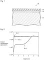
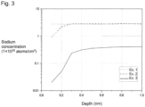
Fig. 2 is a graph illustrating the relation between, of a silicon oxide layer-provided substrate, the depth from a surface in contact with a water/oil repellent layer, and the sodium concentration at the depth obtained by TOF-SIMS. -
Fig. 3 is a graph having the horizontal axis ofFig. 2 expanded. - In this specification, a compound represented by the formula (1) will be referred to as compound (1). The same applies to compounds represented by other formulae.
- Meanings of the following terms in this specification are as follows.
- An "alkali metal" means lithium (Li), sodium (Na), potassium (K), rubidium (Rb) and cesium (Cs).
- A "hydrolyzable silyl group" means a group capable of forming a silanol group (Si-OH) when hydrolyzed. For example, it is -SiR13 n1X1 3-n1 in the formula (1).
- An "etheric oxygen atom" means an oxygen atom forming an ether bond (-O-) between carbon atoms. The chemical formula of an oxyperfluoroalkylene group is represented such that the oxygen atom is on the right side of the perfluoroalkylene group.
- The water/oil repellent layer-provided article of the present invention comprises a substrate, a water/oil repellent layer, and a silicon oxide layer containing alkali metal atoms, present between the substrate and the water/oil repellent layer.
-
Fig. 1 is a cross sectional view illustrating an example of a water/oil repellent layer-provided article of the present invention. The water/oil repellent layer-providedarticle 10 comprises asubstrate 12, asilicon oxide layer 14 formed on the surface of thesubstrate 12 and a water/oil repellent layer 16 formed on the surface of thesilicon oxide layer 14. - The substrate in the present invention is not particularly limited so long as it is a substrate which is required to have water/oil repellency imparted. As a material of the substrate, a metal, a resin, glass, sapphire, a ceramic, a stone, or a composite material thereof may be mentioned. Glass may be chemically tempered.
- As the substrate, a substrate for a touch panel or a substrate for a display is suitable, and a substrate for a touch panel is particularly suitable. The substrate for a touch panel has translucency. "Having translucency" means that the normal incidence visible light transmittance in accordance with JIS R3106: 1998 (ISO9050: 1990) being at least 25%. As a material of the substrate for a touch panel, glass or a transparent resin is preferred.
- The substrate may have either one of or both surfaces treated by corona discharge treatment, plasma treatment or plasma graft polymerization treatment. Since the treated surface is more excellent in adhesion to the silicon oxide layer, whereby the water/oil repellent layer will be more excellent in abrasion resistance. Accordingly, it is preferred to apply the treatment to the surface to be in contact with the silicon oxide layer of the substrate. Among these treatments, preferred is corona discharge treatment, whereby the water/oil repellent layer will be more excellent in abrasion resistance.
- The corona treatment is conducted with a discharge amount (W·min/m2) preferably as large as possible in accordance with the type of the substrate, since the degree of surface modification of the substrate tends to change in proportion to the electric power charged.
- The silicon oxide layer contains silicon oxide and alkali metal atoms. In view of production efficiency, it preferably contains silicon oxide and sodium. The silicon oxide is preferably a condensate of silicic acid or a hydrolyzed condensate of an alkoxysilane. In view of more excellent adhesion to the water/oil repellent layer and thus more excellent abrasion resistance of the water/oil repellent layer, a condensate of silicic acid is more preferred.
- The thickness of the silicon oxide layer is preferably from 2 to 200 nm, particularly preferably from 2 to 20 nm. When the thickness of the silicon oxide layer is at least the lower limit value of the above range, sufficient effects to improve the adhesion by the silicon oxide layer tend to be obtained. When the thickness of the silicon oxide layer is at most the upper limit value of the above range, the silicon oxide layer itself has high abrasion resistance. The method of measuring the thickness of the silicon oxide layer is not particularly limited and for example, a method by observing a cross section of the silicon oxide layer by an electron microscope (such as SEM or TEM) or a method of using an optical interference film thickness meter, a spectroscopic ellipsometer or a profiler may, for example, be mentioned.
- In the silicon oxide layer, the average concentration of the alkali metal atoms in a region with a depth from the surface in contact with the water/oil repellent layer of from 0.1 to 0.3 nm is at least 2.0×10¹⁹ atoms/cm3, preferably at least 5.0×10¹⁹ atoms/cm3, particularly preferably at least 1.5×10²⁰ atoms/cm3. When the average concentration of the alkali metal atoms is at least the above lower limit value, the adhesion between the silicon oxide layer and the water/oil repellent layer will be excellent and as a result, the water/oil repellent layer will be excellent in abrasion resistance. The reason is not clearly understood, however, the following mechanism is considered. That is, the average concentration of the alkali metal atoms being high means that Si-OM (wherein M is an alkali metal) having high reactivity is present in a large amount on the surface of the silicon oxide layer. Si-OM has high reactivity with a silanol group (Si-OH) formed by hydrolysis of the hydrolyzable silyl group in the fluorinated compound having a hydrolyzable silyl group used for forming the water/oil repellent layer. Accordingly, presence of Si-OM in a large amount leads to an increase of the Si-O-Si bond by which the silicon oxide layer and the water/oil repellent layer are connected. As a result, the water/oil repellent layer will hardly be separated, and the water/oil repellent layer will be excellent in abrasion resistance.
- The concentration of the alkali metal atoms in the present invention means, in a case where only one type of the alkali metal atoms are contained in the region, the concentration of the alkali metal atoms, and in a case where two or more types of the alkali metal atoms are contained in the region, the total concentration of these alkali metal atoms.
- Accordingly, in a case where two or more types of the alkali metal atoms are contained in the region and even in a case where the average concentrations of the respective alkali metal atoms are respectively less than the above lower limit value, the requirement of the present invention is met so long as the average concentration of the total alkali metal atoms is at least the above lower limit value.
- Specifically, for example, when the alkali metal atoms contained in the region include Na, and the average Na atom concentration in the region is at least 2.0×10¹⁹ atoms/cm3, the requirement regarding the alkali metal atom concentration in the present invention is met regardless of whether alkali metal atoms other than Na are present or not. Further, when the alkali metal atoms contained in the region are Na and K and even when the average Na atom concentration and the average K atom concentration in the region are respectively less than 2.0×10¹⁹ atoms/cm3, so long as the sum of the average Na atom concentration and the average K atom concentration is at least 2.0×10¹⁹ atoms/cm3, the requirement regarding the alkali metal atom concentration in the present invention is met.
- The upper limit value of the average alkali metal atom concentration is 4.0×10²² atoms/cm3, preferably 1.0×10²² atoms/cm3, with a view to sufficiently forming the Si-O-Si bond in the silicon oxide layer and sufficiently securing mechanical properties of the silicon oxide layer.
- The average concentration of the alkali metal atoms may be obtained in such a manner that a depth-direction profile of the alkali metal atom concentration is obtained by TOF-SIMS (Time-of-Flight Secondary Ion Mass Spectrometry) depth profiling by ion sputtering, and the average alkali metal atom concentration in a region with a depth of from 0.1 to 0.3 nm in the profile is calculated.
- TOF-SIMS depth profiling by ion sputtering is conducted by alternately repeating measurement by TOF-SIMS and etching of the surface by ion sputtering using an ion gun built into the TOF-SIMS apparatus.
- In the present invention, the reason why the alkali metal atom concentration in a region with a depth from the surface in contact with the water/oil repellent layer of less than 0.1 nm in the silicon oxide layer is excluded is that if the surface of the silicon oxide layer is contaminated with external substances including an alkali metal, the contamination with the alkali metal is reflected in the alkali metal atom concentration profile in the region, and thus the alkali metal atom concentration derived from Si-OM in the silicon oxide layer may not accurately be measured.
- The surface roughness (Ra) of the surface (the interface with the water/oil repellent layer) of the silicon oxide layer measured by a scanning probe microscope is preferably at least 0.5 nm from the viewpoint of abrasion resistance. The upper limit of the roughness is not particularly limited, and is preferably at most 10 nm.
- The silicon oxide layer is not particularly limited and is preferably a layer formed on the surface of the substrate by wet coating method using a coating fluid consisting of a solution containing a precursor of silicon oxide, an alkali metal source and a solvent (such as water or a water-soluble organic solvent) or a layer formed on the surface of the substrate by dry coating method using silicon oxide containing alkali metal atoms. The details will be described later.
- The water/oil repellent layer in the present invention comprises a hydrolyzed condensate of a fluorinated compound having a hydrolyzable silyl group.
- A silanol group (Si-OH) is formed by hydrolysis of the hydrolyzable silyl group (for example, SiR13 n1X1 3-n1) in the formula (1) in the fluorinated compound having a hydrolyzable silyl group, and such silanol groups are intermolecularly condensed to form a Si-O-Si bond, or the silanol group in the fluorinated compound is condensed with a silanol group (Si-OH) or a OM group (Si-OM) on the surface of the silicon oxide layer to form a chemical bond (Si-O-Si bond). That is, the water/oil repellent layer of the present invention contains the fluorinated compound having a hydrolyzable silyl group in a state where some of or all the hydrolyzable silyl groups in the compound are hydrolyzed and condensed.
- The thickness of the water/oil repellent layer is preferably from 1 to 100 nm, particularly preferably from 1 to 50 nm. When the thickness of the water/oil repellent layer is at least the lower limit value of the above range, effects by the surface treatment tend to be sufficiently obtained. When the thickness of the water/oil repellent layer is at most the upper limit value of the above range, high utilization efficiency tends to be obtained.
- In the present invention, the thickness obtained by an X-ray diffractometer for thin film analysis is defined as the thickness of the water/oil repellent layer. The thickness of the water/oil repellent layer is calculated from the oscillation period of an interference pattern of reflected X-rays obtained by X-ray reflectometry using an X-ray diffractometer for thin film analysis (manufactured by Rigaku Corporation, ATX-G).
- The fluorinated compound having a hydrolyzable silyl group (hereinafter sometimes referred to simply as "fluorinated compound") is not particularly limited so long as it is capable of forming a water/oil repellent layer. That is, the fluorinated compound is to form a water/oil repellent layer on the exposed surface of the silicon oxide layer.
- The fluorinated compound may, for example, be a fluorinated compound having a fluoroalkyl group and a hydrolyzable silyl group, or a fluorinated compound having a group having an etheric oxygen atom between carbon atoms of a fluoroalkyl group and a hydrolyzable silyl group. The fluorinated compound is preferably a fluorinated compound having a perfluoroalkyl group and a hydrolyzable silyl group, or a fluorinated compound having a group having an etheric oxygen atom between carbon atoms of a perfluoroalkyl group and a hydrolyzable silyl group, whereby a water/oil repellent layer excellent in water/oil repellency, fingerprint stain removability, lubricity, etc. can be formed. Further, the fluorinated compound is also preferably a fluorinated compound having a fluoroalkyl group, a hydrolyzable silyl group and a poly(oxyfluoroalkylene) chain (hereinafter sometimes referred to as "fluorinated ether compound"), whereby a water/oil repellent layer excellent in water/oil repellency, fingerprint stain removability, lubricity, etc. can be formed.
- The fluoroalkyl group is, in view of excellent water/oil repellency and low burden on the environment, preferably a C1-20 fluoroalkyl group, more preferably a C1-10 fluoroalkyl group, further preferably a C1-6 fluoroalkyl group, particularly preferably a C1-6 linear fluoroalkyl group.
- The perfluoroalkyl group is, in view of excellent water/oil repellency and low burden on the environment, preferably a C1-20 perfluoroalkyl group, more preferably a C1-10 perfluoroalkyl group, further preferably a C1-6 perfluoroalkyl group, particularly preferably a C1-6 linear perfluoroalkyl group.
- The fluorinated compound having a perfluoroalkyl group and a hydrolyzable silyl group may, for example, be a compound represented by the formula (3) in
JP-A-2009-139530 - The fluorinated ether compound has preferably at least 2, particularly preferably at least 3 hydrolyzable silyl groups, in view of more excellent abrasion resistance of the water/oil repellent layer. The upper limit of the number of the hydrolyzable silyl groups is not particularly limited, and in view of production efficiency, preferably 15, particularly preferably 12.
- The poly(oxyfluoroalkylene) chain is preferably one composed of C1-10 oxyfluoroalkylene groups, particularly preferably C1-10 oxyperfluoroalkylene groups. In view of more excellent abrasion resistance and fingerprint stain removability of the water/oil repellent layer, preferred is one composed of a plural types of C1-10 oxyperfluoroalkylene groups. Such a poly(oxyfluoroalkylene) chain may, for example, be one composed of a plurality of C1 oxyperfluoroalkylene groups and a plurality of C2 oxyperfluoroalkylene groups, one composed of C1 oxyperfluoroalkylene groups and a plurality of C3 oxyperfluoroalkylene groups, one composed of a plurality of C2 oxyperfluoroalkylene groups and C3 oxyperfluoroalkylene groups, one composed of a plurality of C2 oxyperfluoroalkylene groups and C3 oxyperfluoroalkylene groups, or one composed of a plurality of C2 oxyperfluoroalkylene groups and a plurality of C4 oxyperfluoroalkylene groups. The plurality of oxyperfluoroalkylene groups may be arranged in blocks, randomly or alternately. In a case where the number of carbon atoms in the oxyperfluoroalkylene group is at least 2, preferred is a linear oxyperfluoroalkylene group.
- The poly(oxyperfluoroalkylene) chain is particularly preferably one composed of C2 linear oxyperfluoroalkylene groups and C4 linear oxyperfluoroalkylene groups alternately arranged.
- As the fluorinated ether compound, compound (X) may be mentioned.
[A1-O-(Rf1O)m1]a-Q-[SiR13 n1X1 3-n1]b (X)
wherein A' is a C1-20 perfluoroalkyl group, Rf1 is a C1-10 fluoroalkylene group, m1 is an integer of from 2 to 210, (Rf1O)m1 may be one composed of two or more types of Rf1O differing in the number of carbon atoms, "a" and "b" are each independently an integer of at least 1, Q is a (a+b) valent linking group, R13 is a hydrogen atom or a monovalent hydrocarbon group, X1 is a hydrolyzable group, n1 is an integer of from 0 to 2, and all of three [SiR13 n1X1 3-n1] may not necessarily be the same groups. - A' is, in view of more excellent lubricity and abrasion resistance of the water/oil repellent layer, preferably a C1-20 perfluoroalkyl group, more preferably a C1-10 perfluoroalkyl group, further preferably a C1-6 perfluoroalkyl group, particularly preferably a C1-3 perfluoroalkyl group.
- Rf1 is preferably linear. Further, Rf1 may be a perfluoroalkylene group or may be a fluoroalkylene group having at least one hydrogen atom.
- Rf1 is preferably the same as the oxyperfluoroalkylene group constituting the above-described preferred poly(oxyperfluoroalkylene) chain.
- m1 is an integer of from 2 to 210, preferably an integer of from 5 to 160, particularly preferably an integer of from 10 to 110. When m1 is at least the lower limit value of the above range, the water/oil repellent layer will be excellent in water/oil repellency. When m1 is at most the upper limit value of the above range, the water/oil repellent layer will be excellent in abrasion resistance.
- In a case where in (Rf1O)m1, two or more types of Rf1O differing in the number of carbon atoms are present, the bonding order of the respective Rf1O is not limited. For example, in a case where two types of Rf1O are present, the two types of Rf1O may be arranged randomly, alternately or in blocks.
- "a" is preferably an integer of from 1 to 10, particularly preferably an integer of from 1 to 4.
- (a+b) is preferably an integer of from 2 to 15, particularly preferably an integer of from 2 to 12.
- When "a" is 1, b is preferably from 1 to 10, particularly preferably from 1 to 5.
- When "a" is an integer of at least 2, b is preferably an integer of at least 1, more preferably an integer of from 1 to 10, particularly preferably an integer of from 1 to 4.
- Q may, for example, be a (a+b) valent alkane group, a group having an atom or a group such as an etheric oxygen atom or an amide group inserted between carbon atoms of the alkane group, or a group having one or more hydrogen atoms bonded to the carbon atom of such a group substituted by a fluorine atom.
- SiR13 n1X1 3-n1 is a hydrolyzable silyl group.
- X1 is a hydrolyzable group. The hydrolyzable group is a group converted to a hydroxy group by hydrolysis. That is, Si-X1 at the terminal of the compound (X) is converted to a silanol group (Si-OH) by hydrolysis.
- X1 may, for example, be an alkoxy group, a halogen atom, an acyl group or an isocyanate group (-NCO). The alkoxy group is preferably a C1-4 alkoxy group.
- R13 is a hydrogen atom or a monovalent hydrocarbon group. The monovalent hydrocarbon group may, for example, be an alkyl group, a cycloalkyl group, an alkenyl group or an allyl group.
- R13 is preferably a monovalent hydrocarbon group, particularly preferably a monovalent hydrocarbon group. The number of carbon atoms in the monovalent saturated hydrocarbon group is preferably from 1 to 6, more preferably from 1 to 3, particularly preferably 1 or 2. When the number of carbon atoms of R13 is within such a range, the compound (X) is easily produced.
- n1 is preferably 0 or 1, particularly preferably 0. By the presence of a plurality of X1 in one hydrolyzable silyl group, adhesion to the substrate will be stronger.
- All of three SiR13 n1X1 3-n1 in the compound (X) may be the same groups, or all may not be the same groups. In view of production efficiency of the compound (X), all of three SiR13 n1X1 3-n1 are preferably the same group.
- As specific examples of the compound (X), for example, the after-described compound (1), a fluorinated ether compound disclosed in
WO2013/042732 ,WO2013/121984 ,WO2013/121985 ,WO2013/121986 ,WO2014/163004 ,WO2015/087902 ,WO2017/038830 ,WO2017/038832 ,WO2017/187775 ,JP-A-2014-080473 JP-A-2015-199906 WO2011/059430 orWO2011/060047 , a silicon-containing organic fluorinated polymer disclosed inJapanese Patent No. 2874715 JP-A-2000-327772 JP-A-H11-029585 JP-A-2002-506887 Japanese Patent No. 4138936 JP-A-2015-199906 JP-A-2016-204656 JP-A-2016-210854 JP-A-2016-222859 WO2012/064649 , an organic silicon compound disclosed inJP-A-2000-144097 JP-A-2008-534696 JP-A-2014-070163 U.S. Patent Application Publication No. 2010/0129672 may be mentioned. - As commercial products of the compound (X), KY-100 series (KY-178, KY-185, KY-195, etc.) manufactured by Shin-Etsu Chemical Co., Ltd., Afluid (registered trademark) S550 manufactured by Asahi Glass Company, Limited, OPTOOL (registered trademark) DSX, OPTOOL (registered trademark) AES, OPTOOL (registered trademark) UF503, OPTOOL (registered trademark) UD509, etc., manufactured by DAIKIN INDUSTRIES LTD. may, for example, be mentioned.
- The compound (1) is an example of the compound (X).
A1-O-(Rf1O)m1-Q1-[C(O)N(R1)]p1-Q2-[SiR13 n1X1 3-n1]b2 (1)
wherein Q2 is -R11-C(-R12-)3 or R13, and when Q2 is -R11-C(-R12-)3, b2 is 3, and when Q2 is R13, b2 is 1. - In the compound (1), A1, Rf1, m1, R13, X1 and n1 are the same as in the above formula (X), Q1 is a linear C1-10 fluoroalkylene group, R1 is a hydrogen atom or a C1-10 alkyl group, p1 is 0 or 1, R11 is a single bond, an alkylene group, a group having an etheric oxygen atom at the terminal (the terminal on the side bonded to C(-R12-)3) of an alkylene group, a group having an etheric oxygen atom between carbon atoms of an alkylene group having at least 2 carbon atoms, or a group having an etheric oxygen atom at the terminal (the terminal on the side bonded to C(-R12-)3) and between carbon atoms of an alkylene group having at least 2 carbon atoms, and R12 and R13 are each independently an alkylene group, a group having an etheric oxygen atom at the terminal (excluding the terminal on the side bonded to Si) of an alkylene group, or a group having an etheric oxygen atom between carbon atoms of an alkylene group having at least 2 carbon atoms.
- Q1 may be a linear perfluoroalkylene group, or may be a linear fluoroalkylene group containing at least one hydrogen atom. By the compound (1) wherein Q1 is linear, a water/oil repellent layer excellent in abrasion resistance and lubricity can be formed.
- When p1 is 1, the compound (1) has an amide bond, however, by the carbon atom at the terminal on the side bonded to [C(O)N(R1)] of Q1 having at least one fluorine atom bonded, the polarity of the amide bond tends to be small, and the water/oil repellency of the water/oil repellent layer is less likely to lower. Whether p1 is 0 or 1 can be selected in view of production efficiency.
- R1 in the [C(O)N(R1)]p1 group is preferably a hydrogen atom in view of production efficiency of the compound (1). When R1 is an alkyl group, the alkyl group is preferably a C1-4 alkyl group.
- When p1 is 0, R11 is, in view of production efficiency of the compound (1), preferably a single bond or a group selected from the group consisting of -CHzO-, - CH2OCH2-, -CH2OCH2CH2O- and -CH2OCH2CH2OCH2- (provided that the left side is bonded to Q1).
- When p1 is 1, R11 is, in view of production efficiency of the compound (1), preferably a single bond or a group selected from the group consisting of -CH2- and - CH2CH2-.
- The R12 and R13 groups are, in view of production efficiency of the compound (1), each independently preferably a group selected from the group consisting of -CH2CH2-, -CH2CH2CH2-, -CH2OCH2CH2CH2- and -OCH2CH2CH2- (provided that the right side is bonded to Si).
- All of the three R12 in the compound (1) may be the same groups or may not be the same groups.
- -(Rf1O)m1-Q1- in the compound (1) is, in view of more excellent abrasion resistance and fingerprint stain removability of the water/oil repellent layer, preferably -Q11-(RF1O)m10-Q12-, wherein Q11 is a single bond, a linear fluoroalkylene group containing at least one hydrogen atom, a group having an etheric oxygen atom at the terminal (excluding the terminal on the side bonded to A'-O) of a linear fluoroalkylene group containing at least one hydrogen atom, a group having an etheric oxygen atom between carbon atoms of a linear fluoroalkylene group having at least 2 carbon atoms and containing at least one hydrogen atom, or a group having an etheric oxygen atom at the terminal (excluding the terminal on the side bonded to A'-O) and between carbon atoms of a linear fluoroalkylene group having at least 2 carbon atoms and containing at least one hydrogen atom (provided that the number of oxygen atoms is at most 10), RF1 is a linear perfluoroalkylene group, m10 is an integer of from 2 to 200, (RF1O)m10 may be one consisting of two or more types of RF1O differing in the number of carbon atoms, and Q12 is a linear perfluoroalkylene group, a linear fluoroalkylene group containing at least one hydrogen atom, or a group having an etheric oxygen atom between carbon atoms of a linear fluoroalkylene group having at least 2 carbon atoms and containing at least one hydrogen atom.
- In a case where Q11 is a linear fluoroalkylene group containing at least one hydrogen atom, or a group having an etheric oxygen atom between carbon atoms of a linear fluoroalkylene group having at least 2 carbon atoms and containing at least one hydrogen atom, and where no etheric oxygen atom is present at the terminal on the side bonded to (RF1O)m10 of Q11, the carbon atom at the terminal on the side bonded to (RF1O)m10 of Q11 has at least one hydrogen atom bonded.
- Q11 is, in view of production efficiency of the compound (11), preferably a single bond or a group selected from the group consisting of -CHFCF2OCH2-, - CF2CHFCF2OCH2-, -CF2CF2CHFCF2OCH2-, -CF2CF2OCHFCF2OCH2-, - CF2CF2OCF2CF2OCHFCF2OCH2-, -CF2CH2OCH2- and -CF2CF2OCF2CH2OCH2-(provided that the left side is bonded to A1-O).
- Preferred embodiment of RF1 is the same as the above-described preferred embodiment of Rf1.
- The preferred range of m10 is the same as the above-described preferred range of m1.
- In a case where in (RF1O)m10, two or more types of RF1O differing in the number of carbon atoms are present, the bonding order of the respective RF1O is not limited.
- (RF1O)m10 may, for example, be {(CF2O)m11(CF2CF2O)m12}, (CF2CF2O)m13, (CF2CF2CF2O)m14 or (CF2CF2O-CF2CF2CF2CF2O)m15.
- Here, m11 is an integer of at least 1, m12 is an integer of at least 1, m11+m12 is an integer of from 2 to 200, and the bonding order of m11 pieces of CF2O and m12 pieces of CF2CF2O is not limited. m13 and m14 are an integer of from 2 to 200, and m15 is an integer of from 1 to 100. Further, {(CF2O)m11(CF2CF2O)m12} represents a random copolymer chain of (CF2O) and (CF2CF2O) having m11 pieces of (CF2O) and m12 pieces of (CF2CF2O).
- When p1 is 0, Q12 is, for example, in a case where (RF1O)m10 is {(CF2O)m11(CF2CF2O)m12} or (CF2CF2O)m13, a C1 perfluoroalkylene group, in a case where (RF1O)m10 is (CF2CF2CF2O)m14, a C2 perfluoroalkylene group, and in a case where (RF1O)m10 is (CF2CF2O-CF2CF2CF2CF2O)m15, a C3 linear perfluoroalkylene group.
- When p1 is 1, as Q12, the following groups may be mentioned.
- (i) A perfluoroalkylene group
- (ii) A group having RFCH2O (wherein RF is a perfluoroalkylene group) on the side bonded to (RF1O)m10 and having a fluoroalkylene group (which may have an etheric oxygen atom between carbon atoms) containing at least one hydrogen atom on the side bonded to C(O)N(R1).
- As Q12 in (ii), in view of production efficiency of the compound (1), the following groups are preferred.
- -RFCH2O-CF2CHFOCF2CF2CF2-, -RFCH2O-CF2CHFCF2OCF2CF2-, -RFCH2O-CF2CHFCF2OCF2CF2CF2-, -RFCH2O-CF2CHFOCF2CF2CF2OCF2CF2-.
- By the compound (1) wherein Q12 is linear, a water/oil repellent layer excellent in abrasion resistance and lubricity can be formed.
- As the compound (1), for example, the following compounds may be mentioned. The compounds are preferred in that they are industrially easily produced, easily handled, and capable of forming a water/oil repellent layer more excellent in water/oil repellency, abrasion resistance, fingerprint stain removability, lubricity and outer appearance.


PFPE-CH2OCH2CH2CH2-Si(OCH3)3
PFPE-CH2OCH2CH2CH2-Si(OCH2CH3)3
PFPE-CH2OCH2CH2CH2-Si(CH3)(OCH3)2
PFPE-C(O)NH-CH2CH2CH2-Si(OCH3)3
PFPE-C(O)NH-CH2CH2CH2-Si(OCH2CH3)3
PFPE-C(O)NH-CH2CH2CH2-Si(CH3)(OCH3)2
- Here, PFPE is a polyfluoropolyether chain, that is, A1-O-Q11-(RF1O)m10-Q12-. A preferred embodiment of PFPE is a combination of the above-described preferred A1, Q11, (RF1O)m10 and Q12.
- The method for producing a water/oil repellent layer-provide article of the present invention is a method for producing a water/oil repellent layer-provided article, comprising (a) forming a silicon oxide layer containing alkali metal atoms on the surface of a substrate using a silicon oxide-forming material containing a silicon oxide precursor and an alkali metal source, and then (b) forming on the surface of the silicon oxide layer a water/oil repellent layer comprising a hydrolyzed condensate of a fluorinated compound having a hydrolyzable silyl group, wherein the silicon oxide layer is a silicon oxide layer having the above alkali metal atom concentration.
- The silicon oxide precursor may, for example, be silicic acid, a partial condensate of silicic acid, an alkali metal silicate, a silane compound having a hydrolyzable group bonded to the silicon atom, or a partially hydrolyzed condensate of the silane compound. Silicic acid or its partial condensate may be formed into silicon oxide by dehydration condensation, the alkali metal silicate may be formed into silicic acid or its partial condensate by an acid or a cation exchange resin, and the formed silicic acid or its partial condensate may be formed into silicon oxide by dehydration condensation. The hydrolyzable group in the silane compound having a hydrolyzable group bonded to the silicon atom may, for example, be an alkoxy group or a chlorine atom. The hydrolyzable group in the silane compound may be hydrolyzed to form a hydroxy group, and the formed silanol compound may be formed into silicon oxide by dehydration condensation. The silane compound having a hydrolyzable group bonded to the silicon atom may, for example, be an alkoxysilane such as a tetraalkoxysilane or an alkyltrialkoxysilane, or tetrachlorosilane.
- The silicon oxide precursor is preferably silicic acid, a partial condensate of silicic acid, a tetraalkoxysilane or its partially hydrolyzed condensate.
- The alkali metal source may, for example, be an alkali metal hydroxide or a water-soluble alkali metal salt. The water-soluble alkali metal salt may, for example, be an alkali metal carbonate, an alkali metal hydrogen carbonate, an alkali metal hydrochloride or an alkali metal nitrate. The alkali metal source is preferably an alkali metal hydroxide or an alkali metal carbonate.
- Further, the alkali metal silicate may be used as the silicon oxide precursor and as the alkali metal source. As mentioned, above, the alkali metal silicate may be converted to silicon oxide via silicic acid, and on that occasion, a small amount of the alkali metal remains in the formed silicon oxide in many cases. Accordingly, silicon oxide containing a predetermined amount of alkali metal atoms can be obtained by adjusting the amount of the remaining alkali metal intentionally.
- As a method of forming the silicon oxide layer containing alkali metal atoms, the following (a1) or (a2) is preferred. The method (a1) is a method employing the above wet coating, and the method (a2) is a method employing the above dry coating.
- (a1): A method of forming a silicon oxide layer on the surface of a substrate by using a coating fluid containing at least one silicon oxide precursor selected from the group consisting of silicic acid, a partial condensate of silicic acid, an alkoxysilane and its partially hydrolyzed condensate, an alkali metal source, and a solvent.
- (a2): A method of forming the silicon oxide layer on the surface of a substrate by using silicon oxide containing alkali metal atoms.
- The coating fluid for forming a silicon oxide layer preferably contains, with a view to easily forming the silicon oxide layer, as the silicon oxide precursor, at least one member selected from the group consisting of silicic acid and its partial condensate, particularly preferably contains a partial condensate of silicic acid.
- It is preferred to use, as a material for producing silicic acid or its partial condensate, an alkali metal silicate. By using an alkali metal silicate, alkali metal atoms can be contained at a predetermined concentration in the formed silicon oxide layer. Otherwise, the alkali metal atom concentration in the formed silicon oxide layer may be adjusted by using an alkali metal source such as an alkali metal hydroxide.
- Specifically, preferred is a preparation method of subjecting an aqueous alkali metal silicate solution to demineralization treatment to obtain an aqueous silicic acid solution, and adding a water-soluble organic solvent to the aqueous silicic acid solution. By properly selecting the demineralization treatment conditions, a preferred amount of the alkali metal atoms can be contained in the aqueous silicic acid solution. As a method of the demineralization treatment, for example, the aqueous alkali metal silicate solution is mixed with a cation exchange resin, followed by stirring, and the cation exchange resin is removed. The alkali metal silicate used in such a method is preferably sodium silicate.
- The alkali metal silicate may be a silicate represented by M2O·nSiO2, specifically, a metasilicate (M2SiO3), an orthosilicate (M4SiO4), a bisilicate (M2Si2O5) or a tetrasilicate (M2SiO4O9).
- For example, as sodium silicate, Na2O·nSiO2 as defined in JIS K1408-1966 may be mentioned, and specifically, sodium metasilicate (Na2SiO3), sodium orthosilicate (Na4SiO4), sodium bisilicate (Na2Si2O5) or sodium tetrasilicate (Na2Si4O9) may, for example, be mentioned.
- The solvent is preferably water or a water-soluble organic solvent. The water-soluble organic solvent may, for example, be an alcohol organic solvent, a ketone organic solvent, an ether organic solvent or an ester organic solvent, and is preferably an alcohol organic solvent. The alcohol organic solvent may, for example, be isopropyl alcohol, ethanol or n-butanol.
- The solid content concentration (as calculated as SiO2) of coating fluid is preferably from 0.001 to 10 mass%, particularly preferably from 0.1 to 3 mass%.
- As a method of applying the coating fluid to the surface of a substrate by wet coating, a spin coating method, a wipe coating method, a spray coating method, a squeegee coating method, a dip coating method, a die coating method, an ink-jet method, a flow coating method, a roll coating method, a casting method, a Langmuir-Blodgett method or a gravure coating method may, for example, be mentioned.
- The coating fluid is applied to the surface of a substrate by wet coating to form a wet film, and then the solvent in the wet film is removed, and the silicic acid and its partial condensate are condensed to form the silicon oxide layer.
- The temperature when the solvent is removed from the wet film and the temperature at the time of condensation of silicic acid and its partial condensate are preferably from 0 to 600°C, and with a view to forming a dense silicon oxide layer, particularly preferably from 200 to 600°C.
- As the method of carrying out dry coating using silicon oxide containing alkali metal atoms, in view of excellence in simplicity of the process, a vacuum deposition method, a CVD method or a sputtering method may, for example, be mentioned. In view of simplicity of apparatus, a vacuum deposition method is particularly preferred.
- In a case where at least two types of silicon oxide containing alkali metal atoms are deposited by the vacuum deposition method, they are deposited from one deposition source, or may be co-deposited from separate deposition sources. Particularly preferred is to use one deposition source consisting of silicon oxide containing alkali metal atoms. For example, in a case where a silicon oxide layer containing two or more types of alkali metal atoms is to be formed, it is preferred to use one deposition source consisting of silicon oxide containing two or more types of alkali metal atoms.
- The alkali metal atom-containing silicon oxide used in the dry coating method, such as the deposition source in the vacuum deposition method, is preferably an alkali metal atom-containing silicon oxide wherein the content of the alkali metal atoms is at least 200 ppm to Si. The content of the alkali metal atoms to Si is more preferably at least 1,000 ppm, particularly preferably at least 10,000 ppm. When the content of the alkali metal atoms is at least the lower limit value of the above range, excellent adhesion between the formed silicon oxide layer and the water/oil repellent layer will be achieved and as a result, the water/oil repellent layer will be excellent in abrasion resistance. The upper limit of the content of the alkali metal atoms to Si is preferably 200,000 ppm, particularly preferably 100,000 ppm.
- As a method for producing the alkali metal atom-containing silicon oxide, a method of adding silicon dioxide to an alkali metal source-containing aqueous solution, followed by stirring, and removing water may be mentioned. As the silicon dioxide, porous silicon dioxide such as silica gel is preferred. The alkali metal source-containing aqueous solution may, for example, be an aqueous alkali metal hydroxide solution or an aqueous alkali metal carbonate solution. Otherwise, the alkali metal atom-containing silicon oxide may be produced from the coating fluid for forming a silicon oxide layer in the above method (a1).
- Otherwise, porous silica gel containing alkali metal atoms, produced from an alkali metal silicate such as sodium silicate, or porous silica gel containing alkali metal atoms obtained by impregnating the above porous silica gel with an aqueous solution containing an alkali metal source, followed by drying or firing, or the like may be used as the alkali metal atom-containing silicon oxide. As silicon oxide containing alkali metal atoms, commercial products may be used, and porous spherical silica gel produced from sodium silicate such as M. S. GEL (tradename, manufactured by AGC Si-Tech Co., Ltd.) may be mentioned.
- The shape of the alkali metal atom-containing silicon oxide is not limited, and a powder, beads, pellets or cullet may, for example, be mentioned. Preferred is beads, pellets or cullet, which can be easily used as e.g. the deposition source. The method for producing the pellets is not limited, and for example, a method of pressing a powder to form a pellet-shape formed product may be mentioned. The size of the pellet-shape formed product is not particularly limited, and for example, a diameter of at least 1 cm is preferred, since if the pellets are too small, they fly too much at the time of coating, such being unfavorable. As a method for producing cullet, a method of cutting glass obtained by adding calcium by a cutter, followed by grinding may be mentioned.
- After the silicon oxide layer containing alkali metal atoms is formed, on its exposed surface, a water/oil repellent layer comprising a hydrolyzed condensate of a fluorinated compound having a hydrolyzable silyl group is formed. As the forming method, dry coating or wet coating may be mentioned. The exposed surface of the silicon oxide layer in the silicon oxide layer-provided substrate means the surface of the silicon oxide layer on which the water/oil repellent layer is to be formed.
- The dry coating method may, for example, be a vacuum deposition method, a CVD method or a sputtering method, and is particularly preferably a vacuum deposition method, with a view to suppressing deposition of the fluorinated compound having a hydrolyzable silyl group and in view of simplicity of apparatus.
- The temperature at the time of vacuum deposition is preferably from 20 to 300°C, particularly preferably from 30 to 200°C.
- The pressure at the time of vacuum deposition is preferably at most 1×10⁻¹ Pa, particularly preferably at most 1×10⁻² Pa.
- In the dry coating, one type of a fluorinated compound having a hydrolyzable silyl group may be used alone, two or more types of fluorinated compounds having a hydrolyzable silyl group may be used as a mixture, a composition containing a fluorinated compound having a hydrolyzable silyl group and other component (excluding the solvent) may be used, or a solution or dispersion having a solvent added to such a component may be used.
- The wet coating method may, for example, be a spin coating method, a wipe coating method, a spray coating method, a squeeze coating method, a dip coating method, a die coating method, an ink-jet method, a flow coating method, a roll coating method, a casting method, a Langmuir-Blodgett method or a gravure coating method.
- In the wet coating, a coating fluid for forming a water/oil repellent layer is used.
- The coating fluid for forming a water/oil repellent layer is a solution or dispersion containing the fluorinated compound having a hydrolyzable silyl group and a solvent.
- The solvent is preferably an organic solvent. The organic solvent may be a fluorinated organic solvent or may be a non-fluorinated organic solvent, or may contain both the solvents.
- The fluorinated organic solvent may, for example, be a fluorinated alkane, a fluorinated aromatic compound, a fluoroalkylether, a fluorinated alkylamine or a fluoroalcohol.
- The non-fluorinated organic solvent is preferably a compound consisting solely of hydrogen atoms and carbon atoms or a compound consisting solely of hydrogen atoms, carbon atoms and oxygen atoms and may be a hydrocarbon-based organic solvent, an alcohol-based organic solvent, a ketone-based organic solvent, an ether-based organic solvent or an ester-based organic solvent.
- The coating fluid for forming a water/oil repellent layer may contain, in addition to the fluorinated compound having a hydrolyzable silyl group and the solvent, within a range not to impair the effects of the present invention, other components and impurities (such as by-products formed in the process for producing the fluorinated compound having a hydrolyzable silyl group).
- Other components may, for example, be known additives such as an acid catalyst or a basic catalyst which accelerates hydrolysis and condensation of the hydrolyzable silyl group.
- The solid content concentration of the coating fluid for forming a water/oil repellent layer is preferably from 0.001 to 10 mass%, particularly preferably from 0.01 to 1 mass%. The solid content concentration of the coating fluid for forming a water/oil repellent layer is a value calculated from the mass of the coating fluid for forming a water/oil repellent layer before heating and the mass after heating in a convection oven at 120°C for 4 hours.
- In (b), in order to improve abrasion resistance of the water/oil repellent layer, as the case requires, an operation to accelerate the reaction between the fluorinated compound having a hydrolyzable silyl group and the silicon oxide layer may be conducted. Such an operation may, for example, be heating, humidification or light irradiation. For example, the silicon oxide layer-provided substrate having a water/oil repellent layer formed thereon is heated in the air containing moisture to accelerate e.g. hydrolysis of the hydrolyzable silyl group into a silanol group, formation of a siloxane bond by condensation of the silanol group, or condensation of the silanol group and the OM group on the surface of the silicon oxide layer and the silanol group of the fluorinated compound.
- After the surface treatment, the compound in the water/oil repellent layer, which is not chemically bonded to other compound or the silicon oxide layer, may be removed as the case requires. As a specific method, for example, a method of rinsing the water/oil repellent layer with a solvent, or a method of wiping the water/oil repellent layer with cloth impregnated with a solvent may be mentioned.
- Now, the present invention will be described in further detail with reference to Examples. However, it should be understood that the present invention is by no means restricted thereto.
- Ex. 1 to 2, 4 to 8, 9 to 10 and 12 to 30 are Examples of the present invention, and Ex. 3, 11 and 31 are Comparative Examples.
- The number average molecular weight of the fluorinated ether compound was calculated by obtaining the number (average value) of oxyperfluoroalkylene groups based on the terminal group by 1H-NMR and 19F-NMR. The terminal group may, for example, be A' or SiR13 n1X1 3-n1 in the formula (1).
- The thickness of the silicon oxide layer was measured by a spectrum ellipsometer (FE-3000 manufactured by Otsuka Electronics Co., Ltd.).
- The average sodium concentration in a region with a depth from the surface in contact with the water/oil repellent layer of at least 0.1 nm and at most 0.3 nm in the silicon oxide layer, was obtained by using a Time-of-Flight Secondary Ion Mass Spectrometry (TOF-SIMS) apparatus in accordance with the following procedure.
- (I) First, a standard sample for quantitative determination of sodium concentration was prepared. A quartz glass substrate having the same composition as the silicon oxide layer to be evaluated was prepared, and ion implantation of sodium into the substrate was conducted to prepare a standard sample. For ion implantation, a medium-electric current ion implantation apparatus (IMX-3500RS manufactured by ULVAC, Inc.) was used, and the energy was 110 keV and the sodium implantation amount was 6.0×10¹⁴ ions/cm2.
- (II) Then, the silicon oxide layer-provided substrate to be evaluated and the standard sample prepared in (I) were transferred into the TOF-SIMS apparatus simultaneously, TOF-SIMS depth profiling by sputtering was conducted in order, and a profile of the sputtering time (vertical axis) and the intensity of 23Na+ and 28Si+ (horizontal axis) was obtained.
- Then, the sputtering time on the horizontal axis of the obtained profile was converted to the depth employing the depth of the standard sample. The depth of the standard sample was measured by using a stylus surface profiler (Dektak150 manufactured by ULVAC, Inc.).
- Then, the intensity on the vertical axis of the obtained profile was converted into the sodium concentration employing the sputtering rate (0.0282 nm/sec) of sputter ions obtained from the standard sample and RSF (2.8182×10²⁰; relative sensitivity factor) calculated from the depth profile of the standard sample, to obtain the depth profile of the sodium concentration of the silicon oxide layer (
Figs. 2 and3 ). - The TOF-SIMS conditions employed in the Examples were as follows.
- TOF-SIMS apparatus: TOF.SIMS5 manufactured by ION-TOF GmbH
- Primary ion species: Bi1 +
- Primary ion accelerating voltage: 25 keV
- Primary ion current: 1 pA (at 10 kHz)
- Primary ion cluster size: 100×100 µm2
- Primary ion bunching: conducted
- Cycle time: 100 µs
- Number of pixels: 128×128 pixels
- Sputtering ion species: C60 ++
- Sputtering accelerating voltage: 10 keV
- Sputtering current: 1nA (at 10 kHz)
- Sputtering ion cluster size: 400x400 µm2
- Sputtering time per cycle: 1.634 seconds
- Degree of vacuum: 5.0×10⁻⁶ mbar (oxygen flow into measurement chamber conducted)
- Mass number of Na secondary ions: 23
- Mass number of Si secondary ions: 28
- Flood gun: used
- (III) Finally, from the depth profile of the sodium concentration of the silicon oxide layer obtained in (II), the average sodium concentration in a region with a depth from the surface in contact with the water/oil repellent layer of at least 0.1 nm and at most 0.3 nm was calculated. The number of points plotted in the region with a depth of at least 0.1 nm and at most 0.3 nm in the depth profile of the sodium concentration was four. The average sodium concentration was obtained as the average value at these four points. When measurement is conducted under the above conditions, four points may be present in a region with a depth from the surface in contact with the water/oil repellent layer of at least 0.1 nm and at most 0.3 nm.
- It is preferred that the silicon oxide layer is exposed before the TOF-SIMS depth profiling by ion sputtering. That is, in a case where the water/oil repellent layer is present on the surface of the silicon oxide layer or in a case where the surface is distinctly contaminated, they are preferably removed. As the removal method, oxygen plasm ashing treatment or ultraviolet (UV) ozone treatment may, for example, be mentioned. Depending upon the thickness of the water/oil repellent layer or the degree of surface contamination, both should be conducted.
- In Examples, oxygen plasm ashing treatment was conducted, then UV ozone treatment was conducted. For the oxygen plasma ashing treatment, a low temperature ashing apparatus (LTA-102 model manufactured by YANACO BUNSEKI KOGYO) was used. The treatment conditions were such that the radiofrequency output: 50 W, oxygen flow: 50 mL/min, and the treatment time: 60 minutes. For the UV ozone treatment, an ultraviolet irradiation apparatus (PL30-200 manufactured by SEN ENGINEERING CO., LTD.) was used, and UB2001D-20 was used as an ultraviolet irradiation apparatus power source. The treatment conditions were such that the ultraviolet wavelength: 254 nm, and the treatment time was 10 minutes.
- In a case where TOF-SIMS depth profile by ion sputtering is carried out with respect to a water/oil repellent layer-provided article, it is preferred to confirm that fluorine is removed by monitoring the fluorine peak by X-ray photoelectron spectroscopy, although it is unnecessary in Examples since TOF-SIMS depth profiling by ion sputtering with respect to the silicon oxide layer-provided substrate was carried out.
- Further, the concentration of alkali metals other than sodium was also measured in the same manner as the measurement of the sodium concentration.
- Ra was measured by using a scanning probe microscope (manufactured by SII NanoTechnology lnc., model: SPA400). The cantilever was SI-DF40 (with back Al), XY data number was 256, and the scanning area was 10 µm × 10 µm.
- The contact angle of about 2 µL of distilled water placed on the surface of the water/oil repellent layer was measured by a contact angle measuring apparatus (DM-701 manufactured by Kyowa interface Co., Ltd.) at 20°C. Measurement was conducted on different five points on the surface of the water/oil repellent layer, and the average value was calculated.
- With respect to the water/oil repellent layer, the water contact angle was measured in accordance with JIS L0849: 2013 (ISO 105-X12: 2001) using a reciprocating traverse testing machine (manufactured by KNT Co.), wherein steel wool BON STAR (yarn number: #0000, dimensions: 5 mm × 10 mm × 10 mm) was reciprocated under a load of 9.8N at a rate of 80 rpm. The water contact angle of the water/oil repellent layer was measured every predetermined time of abrasion by steel wool, and a case where the water contact angle was at least 100° was rated as O (good), and a case where it was less than 100° was rated as × (poor). The smaller the decrease in water contact angle after abrasion, the smaller the decrease in performance due to abrasion, and the more excellent the abrasion resistance.
- With respect to the water/oil repellent layer, using a felt abrasion testing machine, felt (dimensions: 10 mm × 10 mm × 50 mm) was reciprocated under a load of 9.8N at a rate of 80 rpm. The water contact angle of the water/oil repellent layer was measured after felt abrasion of 1,000 times reciprocation. The smaller the decrease in the water contact angle after abrasion, the smaller the decrease in performance by abrasion, and the more excellent the abrasion resistance.
- Compound (X-1) having a number average molecular weight of 2,900 was obtained in accordance with Example 6 in
WO2013/121984 .
CF3-O-(CF2CF2O-CF2CF2CF2CF2O)m15(CF2CF2O)-CF2CF2CF2-C(O)NHCH2CH2CH2-Si(OCH3)3 (X-1)
- Into 20 g of a 5 mass% aqueous sodium silicate solution (sodium silicate solution No. 3 manufactured by SHOWA CHEMICAL), 12 g of a cation exchange resin (SK1B manufactured by Mitsubishi Chemical Corporation) was added, followed by stirring for 10 minutes. The cation exchange resin was removed by filtration to obtain an aqueous silicic acid solution. 0.25 g of the silicic acid solution was added to 4.75 g of isopropyl alcohol to obtain
coating fluid 1 for forming silicon oxide layer (solid content concentration (as calculated as SiO2): 0.25 mass%. - The
coating fluid 1 for forming silicon oxide layer was subjected to the following measurements and as a result, it was confirmed that a silicon oxide powder containing, to Si, 300 ppm of sodium. 0 ppm of lithium, 0 ppm of potassium, 0 ppm of rubidium and 0 ppm of cesium could be obtained. - The
coating fluid 1 for forming silicon oxide layer was dried at 150°C to remove the organic solvent and water to obtain a silicon oxide powder. The contents of sodium, lithium, potassium, rubidium and cesium to Si contained in the silicon oxide powder were measured by ICP optical emission spectrometer (SPS5520 manufactured by Hitachi High-Tech Science Corporation). - One surface of a glass substrate (Dragontrail (registered trademark) manufactured by Asahi Glass Company, Limited) was subjected to corona discharge treatment by a high frequency power source (CG102A manufactured by KASUGA DENKI, Inc.) at 80V at 3.5A.
- To the treated surface of the glass substrate by the corona discharge treatment, the
coating fluid 1 for forming silicon oxide layer was applied by a spin coating method at a number of revolutions of 3,000 rpm for a rotation time of 20 seconds to form a wet film. The wet film was fired at a firing temperature of 550°C for a firing time of 30 minutes to produce a silicon oxide layer-provided glass substrate having a silicon oxide layer with a thickness of about 10 nm. - By TOF-SIMS, the average sodium concentration in a region with a depth from a surface in contact with the water/oil repellent layer of at least 0.1 nm and at most 0.3 nm in the obtained silicon oxide layer was obtained. The results are shown in
Figs. 2 and3 and Table 1. The sodium concentration at a depth up to 10 nm was obtained by TOF-SIMS. - 0.5 g of compound (X-1) as a deposition source was disposed in a molybdenum boat in a vacuum deposition apparatus (VTR-350M manufactured by ULVAC KIKO Inc.). The silicon oxide layer-provided glass substrate was disposed in the vacuum deposition apparatus, and the vacuum deposition apparatus was evacuated of air until the pressure became at most 5×10⁻³ Pa. The boat was heated to 300°C, and the compound (X-1) was vacuum-deposited on the silicon oxide layer to form a deposited film having a thickness of 10 nm.
- The glass substrate having the deposited film formed thereon was left to stand overnight at a temperature of 25°C under a humidity of 40% to form a water/oil repellent layer having a thickness of 10 nm.
- With respect to the water/oil repellent layer, the initial water contact angle and the abrasion resistance were evaluated. The results are shown in Table 1.
- A silicon oxide layer and a water/oil repellent layer were formed in the same manner as in Ex. 1 except that the firing temperature at the time of forming the silicon oxide layer was changed to 250°C.
- By TOF-SIMS, the average sodium concentration in a region with a depth from a surface in contact with the water/oil repellent layer of at least 0.1 nm and at most 0.3 nm in the obtained silicon oxide layer was obtained. The results are shown in
Figs. 2 and3 and Table 1. - With respect to the water/oil repellent layer, the initial water contact angle and the abrasion resistance were evaluated. The results are shown in Table 1.
- In the same manner as in Ex. 1, one surface of a glass substrate was subjected to corona discharge treatment.
- Silicon oxide (SiO2(C) manufactured by Canon Optron Inc., sodium content to Si measured was less than 1 ppm) as a deposition source was disposed in a molybdenum boat in a vacuum deposition apparatus (VTR-350M manufactured by ULVAC KIKO Inc.). The glass substrate was disposed in the vacuum deposition apparatus, and the vacuum deposition apparatus of evaluated of air until the pressure became at most 5×10⁻³ Pa. The boat was heated to 1 ,000°C, and to the treated surface of the glass substrate by the corona discharge treatment, silicon oxide was vacuum-deposited to form a silicon oxide layer having a thickness of 10 nm.
- By TOF-SIMS, the average sodium concentration in a region with a depth from the surface in contact with the water/oil repellent layer of at least 0.1 nm and at most 0.3 nm in the obtained silicon oxide layer was obtained. The results are shown in
Figs. 2 and3 and Table 1. - A water/oil repellent layer was formed in the same manner as in Ex. 1 except that the silicon oxide layer-provided glass substrate in Ex. 3 was used.
- With respect to the water/oil repellent layer, the initial water contact angle and the abrasion resistance were evaluated. The results are shown in Table 1.
- To 20 g of a 5 mass% aqueous sodium silicate solution (sodium silicate solution No. 3 manufactured by SHOWA CHEMICAL), 4 g of a cation exchange resin (SK1B manufactured by Mitsubishi Chemical Corporation) was added, followed by stirring for 10 minutes. The cation exchange resin was removed by filtration to obtain an aqueous silicic acid solution. 1 g of the aqueous silicic acid solution was added to 4 g of isopropyl alcohol to obtain
coating fluid 2 for forming silicon oxide layer (solid content concentration (as calculated as SiO2): 1 mass%). With respect to thecoating fluid 2 for forming silicon oxide layer, the content of sodium to Si in the obtained silicon oxide powder was measured and found to be 500 ppm. Further, the lithium content was 0 ppm, the potassium content was 0 ppm, the rubidium content was 0 ppm and the cesium content was 0 ppm. - A water/oil repellent layer was formed in the same manner as in Ex. 2 except that the
coating fluid 1 for forming silicon oxide layer was changed to thecoating fluid 2 for forming silicon oxide layer. - The average sodium concentration in a region with a depth from the surface in contact with the water/oil repellent layer of at least 0.1 nm and at most 0.3 nm in the silicon oxide layer was obtained. Further, with respect to the water/oil repellent layer, the initial water contact angle and the abrasion resistance were evaluated. The results are shown in Table 1.
- The
coating fluid 2 for forming silicon oxide layer obtained in Ex. 4 was dried at 150°C and then formed by hydrostatic pressing (one minute under 180 MPa) to obtain formedproduct 1. With respect to the formedproduct 1, the sodium content was measured by ICP optical emission spectrometer (SPS5520 manufactured by Hitachi High-Tech Science Corporation) and found to be 500 ppm. Further, the lithium content was 0 ppm, the potassium content was 0 ppm, the rubidium content was 0 ppm, and the cesium content was 0 ppm. - A silicon oxide layer and a water/oil repellent layer were formed in the same manner as in Ex. 3 except that the deposition source was changed to the formed
product 1. - The average sodium concentration in a region with a depth from the surface in contact with the water/oil repellent layer of at least 0.1 nm and at most 0.3 nm in the silicon oxide layer was obtained. Further, with respect to the water/oil repellent layer, the initial water contact angle and the abrasion resistance were evaluated. The results are shown in Table 1.
- A silicon oxide layer having a thickness of 10 nm was formed in the same manner as in Ex. 5, and further fired at a firing temperature of 250°C for a firing time of 30 minutes. Then, a water/oil repellent layer was formed in the same manner as in Ex. 1.
- The average sodium concentration in a region with a depth from the surface in contact with the water/oil repellent layer of at least 0.1 nm and at most 0.3 nm in the silicon oxide layer was obtained. Further, with respect to the water/oil repellent layer, the initial water contact angle and the abrasion resistance were evaluated. The results are shown in Table 1.
- M.S.GEL-D-100-60A (tradename, manufactured by AGC Si-Tech Co., Ltd., spherical porous silica gel having an average particle size of from 50 to 300 µm, hereinafter referred to as "MS gel") was formed by hydrostatic pressing (one minute under 180 MPa) to obtain formed
product 2. A silicon oxide layer and a water/oil repellent layer were formed in the same manner as in Ex. 5 except that the formedproduct 2 was used instead of the formedproduct 1. Further, with respect to MS gel, the sodium content to Si was measured by ICP optical emission spectrometer (SPS5520 manufactured by Hitachi High-Tech Science Corporation) and found to be 23 ppm. Further, the lithium content was 0 ppm, the potassium content was 0 ppm, the rubidium content was 0 ppm, and the cesium content was 0 ppm. - The average sodium concentration in a region with a depth from the surface in contact with the water/oil repellent layer of at least 0.1 nm and at most 0.3 nm in the silicon oxide layer was obtained. Further, with respect to the water/oil repellent layer, the initial water contact angle and the abrasion resistance were evaluated. The results are shown in Table 1.
- A silicon oxide layer having a thickness of 10 nm was formed in the same manner as in Ex. 7 and further fired at a firing temperature of 250°C for firing time of 30 minutes. Then, a water/oil repellent layer was formed in the same manner as in Ex. 1.
- The average sodium concentration in a region with a depth from the surface in contact with the water/oil repellent layer of at least 0.1 nm and at most 0.3 nm in the silicon oxide layer was obtained. Further, with respect to the water/oil repellent layer, the initial water contact angle and the abrasion resistance were evaluated. The results are shown in Table 1.
[Table 1] Ex. Silicon oxide layer Water contact angle of water/oil repellent layer Average Na concentration in region with depth 0.1 to 0.3 nm [atoms/cm3] Initial [degree] Number of abrasion with steel wool 2,000 4,000 1 2.80×10²⁰ 113.4 ○ ○ 2 2.13×10²⁰ 113.1 ○ ○ 3 1.02×10¹⁹ 111.8 × - 4 2.60×10²⁰ 114.6 ○ ○ 5 2.45×10²⁰ 113.2 ○ ○ 6 2.56×10²⁰ 113.5 ○ ○ 7 5.05×10¹⁹ 112.9 ○ ○ 8 7.34×10¹⁹ 113 ○ ○ - In Ex. 1, 2 and 4, the silicon oxide layer is a layer containing a condensate of silicic acid, and Ex. 5 to 8, it is a layer formed by deposition of sodium-containing silicon oxide. Further, in Ex. 1, 2 and 4 to 8, in the silicon oxide layer, the average sodium concentration in a region with a depth from the surface in contact with the water/oil repellent layer of at least 0.1 nm and at most 0.3 nm was at least 2.0×10¹⁹ atoms/cm3, whereby the water/oil repellent layer was excellent in abrasion resistance.
- By comparison between Ex. 2 and 4, the initial water contact angle is higher in Ex. 4. This is considered to be because the sodium content to Si in the silicon oxide powder formed from the
coating fluid 2 for forming silicon oxide layer in Ex. 4 was higher than the sodium content to Si in the silicon oxide powder formed from thecoating fluid 1 for forming silicon oxide layer in Ex. 2, whereby the surface polarity of the silicon oxide layer is higher in Ex. 4, and molecules of the fluorinated compound having a hydrolyzable silyl group deposited on the silicon oxide layer are more highly oriented. - In Ex. 3, the silicon oxide layer was a deposited film of silicon oxide, and in the silicon oxide layer, the average sodium concentration in a region with a depth from the surface in contact with the water/oil repellent layer of at least 0.1 nm and at most 0.3 nm was less than 2.0×10¹⁹ atoms/cm3, and thus the water/oil repellent layer was inferior in the abrasion resistance.
- A silicon oxide layer and a water/oil repellent layer were formed in the same manner as in Ex. 1 except that a sapphire substrate (manufactured by Namiki Precision Jewel Co., Ltd., diameter: 76.2 mm) not subjected to corona discharge treatment was used instead of the glass substrate.
- By TOF-SIMS, the average sodium concentration in a region with a depth from the surface in contact with the water/oil repellent layer of at least 0.1 nm and at most 0.3 nm in the obtained silicon oxide layer was obtained. Further, with respect to the water/oil repellent layer, the initial water contact angle and the abrasion resistance were evaluated. The results are shown in Table 2.
- A silicon oxide layer and a water/oil repellent layer were formed in the same manner as in Ex. 1 except that a sapphire substrate (manufactured by Namiki Precision Jewel Co., Ltd., diameter: 76.2 mm) having one surface subjected to corona discharge treatment using a high frequency power source (HV2010 manufactured by TANTEC) at 28 kV at 1,000 W at a treatment rate of 1 mm/sec was used instead of the glass substrate. The silicon oxide layer was vacuum-deposited on the treated surface of the sapphire substrate by the corona discharge treatment.
- By TOF-SIMS, the average sodium concentration in a region with a depth from the surface in contact with the water/oil repellent layer of at least 0.1 nm and at most 0.3 nm in the obtained silicon oxide layer was obtained. Further, with respect to the water/oil repellent layer, the initial water contact angle and the abrasion resistance were evaluated. The results are shown in Table 2.
- A silicon oxide layer and a water/oil repellent layer were formed in the same manner as in Ex. 3 except that a sapphire substrate (manufactured by Namiki Precision Jewel Co., Ltd., diameter: 76.2 mm) not subjected to corona discharge treatment was used instead of the glass substrate.
- By TOF-SIMS, the average sodium concentration in a region with a depth from the surface in contact with the water/oil repellent layer of at least 0.1 nm and at most 0.3 nm in the obtained silicon oxide layer was obtained. Further, with respect to the water/oil repellent layer, the initial water contact angle and the abrasion resistance were evaluated. The results are shown in Table 2.
[Table 2] Ex. Silicon oxide layer Water contact angle of water/oil repellent layer [degree] Average Na concentration in region with depth 0.1 to 0.3 nm [atoms/cm3] Initial Number of abrasion with felt 1,000 9 1.86×10²⁰ 109.9 94.5 10 2.89×10²⁰ 109.9 109.9 11 1.02×10¹⁹ 111.2 86.5 - In Ex. 9 and 10, the silicon oxide layer is a layer containing a condensate of silicic acid, and in the silicon oxide layer, the average sodium concentration in a region with a depth from the surface in contact with the water/oil repellent layer of at least 0.1 nm and at most 0.3 nm was at least 2.0×10¹⁹ atoms/cm3, whereby the water/oil repellent layer was excellent in abrasion resistance.
- In Ex. 11, the silicon oxide layer was a deposited film, and in the silicon oxide layer, the average sodium concentration in a region with a depth from the surface in contact with the water/oil repellent layer of at least 0.1 nm and at most 0.3 nm was less than 2.0×10¹⁹ atoms/cm3, and thus the water/oil repellent layer was inferior in the abrasion resistance.
- 2.2 g of sodium hydroxide (manufactured by JUNSEI CHEMICAL CO., LTD.) was dissolved in 24 g of distilled water to obtain a 8.4 mass% aqueous sodium hydroxide solution. 24 g of the 8.4 mass% aqueous sodium hydroxide solution and 20 g of MS gel were mixed so that the aqueous sodium hydroxide solution was absorbed in the MS gel. The MS gel which had absorbed the aqueous sodium hydroxide solution was dried at 25°C for 8 hours and formed by hydrostatic pressing (2 seconds under 50 MPa) and fired at 1,000°C for one hour to obtain formed product 3 (pellets). With respect to the formed
product 3, the sodium content to Si was measured by ICP optical emission spectrometer (SPS5520 manufactured by Hitachi High-Tech Science Corporation). The results are shown in Table 3. Further, the lithium content was 0 ppm, the potassium content was 0 ppm, the rubidium content was 0 ppm, and the cesium content was 0 ppm. - A silicon oxide layer and a water/oil repellent layer were formed in the same manner as in Ex. 3 except that the deposition source was changed to the formed
product 3. - The average sodium concentration in a region with a depth from the surface in contact with the water/oil repellent layer of at least 0.1 nm and at most 0.3 nm in the silicon oxide layer was obtained. Further, with respect to the water/oil repellent layer, the initial water contact angle and the abrasion resistance were evaluated. The results are shown in Table 3.
- A formed product (pellets) was obtained in the same manner as in Ex. 12 except that the conditions for producing the formed product were changed as identified in Table 3. With respect to each formed product, the sodium content to Si was measured by ICP optical emission spectrometer (SPS5520 manufactured by Hitachi High-Tech Science Corporation). The results are shown in Table 3. Further, each formed product had a lithium content of 0 ppm, a potassium content of 0 ppm, a rubidium content of 0 ppm and a cesium content of 0 ppm.
- A silicon oxide layer and a water/oil repellent layer were formed in the same manner as in Ex. 3 except that the deposition source was changed to each formed product.
- The average sodium concentration in a region with a depth from the surface in contact with the water/oil repellent layer of at least 0.1 nm and at most 0.3 nm in the silicon oxide layer was obtained. Further, with respect to the water/oil repellent layer, the initial water contact angle and the abrasion resistance were evaluated. The results are shown in Table 3.
[Table 3] Ex. Formed product production conditions Silicon dioxide Na-containing aqueous solution Drying temperature [°C] Pressing pressure [MPa] Pressing time [sec] Firing temperature [°C] Na content to Si in formed product [ppm] Type Concentration [mass%] 12 MS gel NaOH 8.4 25 50 2 1,000 60,000 13 ↑ NaOH 11.2 25 50 2 1,000 80,000 14 ↑ NaOH 14 25 50 2 1,000 100,000 15 ↑ NaOH 21 25 50 2 1,000 150,000 16 ↑ NaOH 5.6 25 50 2 1,000 40,000 17 ↑ NaOH 2.8 25 50 2 1,000 20,000 18 T NaOH 1.4 25 50 2 1,000 10,000 19 ↑ NaOH 0.7 25 50 2 1,000 5,000 20 ↑ NaOH 0.14 25 50 2 1,000 1,000 21 ↑ NaOH 0.07 25 50 2 1,000 500 22 ↑ NaOH 8.4 25 50 2 600 60,000 23 ↑ NaOH 8.4 25 50 2 200 60,000 24 T NaOH 8.4 25 50 2 25 60,000 25 ↑ NaOH 8.4 25 5 2 1,000 60,000 26 ↑ NaOH 8.4 200 50 60 1,000 60,000 27 ↑ NaOH 8.4 1,000 50 60 1,000 60,000 28 T Na2CO3 8.4 1,200 50 60 1,000 60,000 29 Silica gel NaOH 8.4 25 50 60 1,000 60,000 30 Molten silica powder NaOH 8.4 25 50 60 1,000 60,000 31 MS gel NaOH 0.014 25 50 2 1,000 100 Ex. Silicon oxide layer Water contact angle of water/oil repellent layer Average Na concentration in region with depth 0.1 to 0.3 nm [atoms/cm3] Surface roughness [nm] Initial [degree] Number of abrasion with steel wool 2,000 4,000 6,000 12 3.10×10²¹ 3.7 113 ○ ○ ○ 13 4.10×10²¹ 6.3 112 ○ ○ ○ 14 4.90×10²¹ 6.9 114 ○ ○ ○ 15 8.20×10²¹ 7.2 114 ○ ○ ○ 16 1.60×10²¹ 1.5 113 ○ ○ ○ 17 9.60×10²⁰ 0.9 113 ○ ○ ○ 18 5.40×10²⁰ 0.3 112 ○ ○ × 19 2.60×10²⁰ 0.2 114 ○ ○ × 20 5.60×10¹⁹ 0.2 113 ○ ○ × 21 2.70×10¹⁹ 0.2 113 ○ ○ × 22 2.00×10²¹ 2.5 114 ○ ○ ○ 23 2.20×10²¹ 3.8 113 ○ ○ ○ 24 2.00×10²¹ 4.1 114 ○ ○ ○ 25 2.30×10²¹ 3.3 112 ○ ○ ○ 26 2.10×10²¹ 3.1 114 ○ ○ ○ 27 2.20×10²¹ 3 114 ○ ○ ○ 28 2.20×10²¹ 2.8 113 ○ ○ ○ 29 2.00×10²¹ 3.7 113 ○ ○ ○ 30 1.90×10²¹ 2.9 114 ○ ○ ○ 31 4.90×10¹⁸ 0.2 | 113 ○ × × - In Table 3, silica gel is FUJI SILICA GEL A (tradename, manufactured by FUJI SILYSIA CHEMICAL LTD.), molten silica powder is AEROSIL 200 (tradename, manufactured by NIPPON AEROSIL CO., LTD.), NaOH is sodium hydroxide (manufactured by JUNSEI CHEMICAL CO., LTD.), and Na2CO3 is sodium carbonate (manufactured by JUNSEI CHEMICAL CO., LTD.).
- In Ex. 12 to 30, the silicon oxide layer was a deposited film, and in the silicon oxide layer, the average sodium concentration in a region with a depth from the surface in contact with the water/oil repellent layer of at least 0.1 nm and at most 0.3 nm in the silicon oxide layer was at least 2.0×10¹⁹ atoms/cm3, whereby the water/oil repellent layer was excellent in abrasion resistance.
- In Ex. 31, the silicon oxide layer was a deposited film, and in the silicon oxide layer, the average sodium concentration in a region with a depth from the surface in contact with the water/oil repellent layer of at least 0.1 nm and at most 0.3 nm in the silicon oxide layer was less than 2.0×10¹⁹ atoms/cm3, and thus the water/oil repellent layer was inferior in abrasion resistance.
- A formed product (pellets) was obtained in the same manner as in Ex. 12 except that the conditions for producing the formed product were changed as identified in Table 4. As silicon dioxide, MS gel was used in each Ex. With respect to each formed product, the alkali content to Si was measured by ICP optical emission spectrometer (SPS5520 manufactured by Hitachi High-Tech Science Corporation). The results are shown in Table 4.
- A silicon oxide layer and a water/oil repellent layer were formed in the same manner as in Ex. 3 except that the deposition source was changed to each formed product.
- The average sodium concentration in a region with a depth from the surface in contact with the water/oil repellent layer of at least 0.1 nm and at most 0.3 nm in the silicon oxide layer was obtained. Further, with respect to the water/oil repellent layer, the initial water contact angle and the abrasion resistance were evaluated. The results are shown in Table 4.
[Table 4] Ex. Formed product production conditions Alkali metal source-containing aqueous solution Drying temperature [°C] Pressing pressure [MPa] Pressing time [sec] Firing temperature [°C] Alkali metal content to Si in formed product [ppm] Type Concentration [mass%] 32 LiOH 5.6 25 50 2 1,000 32,000 33 Li2CO3 5.6 25 50 2 1,000 33,000 34 KOH 5.6 25 50 2 1,000 38,000 35 K2CO3 5.6 25 50 2 1,000 37,000 36 RbOH 5.6 25 50 2 1,000 39,000 37 Rb2CO3 5.6 25 50 2 1,000 38,000 38 CsOH 5.6 25 50 2 1,000 40,000 39 Cs2CO3 5.6 25 50 2 1,000 39,000 40 NaOH+LiOH (molar ratio 1:1) 5.6 25 50 2 1,000 34,000 41 Na2CO3+Li2CO3 (molar ratio 1:1) 5.6 25 50 2 1,000 33,000 42 NaOH+KOH (molar ratio 1:1) 5.6 25 50 2 1,000 37,000 43 NaOH+LiOH+KOH (molar ratio 1:1:1) 5.6 25 50 2 1,000 36,000 Ex. Silicon oxide layer Water contact angle of water/oil repellent layer Average alkali metal concentration in region with depth 0.1 to 0.3 nm [atoms/cm3] Surface roughness [nm] Initial [degree] Number of abrasion with steel wool 2,000 4,000 6,000 32 1.50×10²¹ 1.2 113 ○ ○ ○ 33 1.50×10²¹ 1.3 112 ○ ○ ○ 34 1.70×10²¹ 1.4 114 ○ ○ ○ 35 1.60×10²¹ 1.5 114 ○ ○ ○ 36 1.70×10²¹ 1.9 113 ○ ○ ○ 37 1.70×10²⁰ 1.4 113 ○ ○ ○ 38 1.80×10²⁰ 2 112 ○ ○ ○ 39 1.70×10²⁰ 1.8 114 ○ ○ ○ 40 1.50×10²¹ 1.2 113 ○ ○ ○ 41 1.50×10²¹ 1.4 113 ○ ○ ○ 42 1.60×10²¹ 1.4 114 ○ ○ ○ 43 1.60×10²¹ 1.5 113 ○ ○ ○ - In Table 4, NaOH is sodium hydroxide (manufactured by JUNSEI CHEMICAL CO., LTD.), Na2CO3 is sodium carbonate (manufactured by JUNSEI CHEMICAL CO., LTD.), LiOH is lithium hydroxide (manufactured by JUNSEI CHEMICAL CO., LTD.), Li2CO3 is lithium carbonate (manufactured by JUNSEI CHEMICAL CO., LTD.), KOH is potassium hydroxide (manufactured by JUNSEI CHEMICAL CO., LTD.), K2CO3 is potassium carbonate (manufactured by JUNSEI CHEMICAL CO., LTD.), RbOH is rubidium hydroxide (manufactured by JUNSEI CHEMICAL CO., LTD.), Rb2CO3 is rubidium carbonate (manufactured by JUNSEI CHEMICAL CO., LTD.), CsOH is cesium hydroxide (manufactured by JUNSEI CHEMICAL CO., LTD.), and Cs2CO3 is cesium carbonate (manufactured by JUNSEI CHEMICAL CO., LTD.).
- In Ex. 32 to 43, the silicon oxide layer was a deposited film, and in the silicon oxide layer, the average concentration of the total alkali metal atoms in a region with a depth from the surface in contact with the water/oil repellent layer of at least 0.1 nm and at most 0.3 nm in the silicon oxide layer was at least 2.0×10¹⁹ atoms/cm3, whereby the water/oil repellent layer was excellent in abrasion resistance.
- The water/oil repellent layer-provided article of the present invention is useful as an optical article, a touch panel (e.g. a surface which can be touched by a finger), an antireflection film, SiO2-treated glass, tempered glass, a sapphire substrate, a quartz substrate or a metal mold.
- 10: Water/oil repellent layer-provided article, 12: substrate, 14: silicon oxide layer, 16: water/oil repellent layer.
Claims (14)
- A water/oil repellent layer-provided article, comprising:a substrate,a water/oil repellent layer comprising a hydrolyzed condensate of a fluorinated compound having a hydrolyzable silyl group, anda silicon oxide layer containing alkali metal atoms, present between the substrate and the water/oil repellent layer,wherein in the silicon oxide layer, the average concentration of the alkali metal atoms in a region with a depth from the surface in contact with the water/oil repellent layer of from 0.1 to 0.3 nm, is at least 2.0×10¹⁹ atoms/cm3 and at most 4.0×10²² atoms/cm3.
- The article according to Claim 1, wherein at least part of the alkali metal atoms are sodium atoms.
- The article according to Claim 1 or 2, wherein silicon oxide in the silicon oxide layer comprises a condensate of silicic acid or a hydrolyzed condensate of an alkoxysilane.
- The article according to any one of Claims 1 to 3, wherein silicon oxide in the silicon oxide layer comprises a deposit of silicon oxide containing the alkali metal atoms.
- The article according to any one of Claims 1 to 4, wherein the fluorinated compound is a compound having a hydrolyzable silyl group and a poly(oxyperfluoroalkylene) chain.
- A method for producing a water/oil repellent layer-provided article, comprising:forming a silicon oxide layer containing alkali metal atoms on the surface of a substrate using a silicon oxide-forming material containing a silicon oxide precursor and an alkali metal source, andforming, on the surface of the silicon oxide layer, a water/oil repellent layer comprising a hydrolyzed condensate of a fluorinated compound having a hydrolyzable silyl group,wherein the silicon oxide layer is a silicon oxide layer in which the average concentration of the alkali metal atoms in a region with a depth from the surface in contact with the water/oil repellent layer of from 0.1 to 0.3 nm is at least 2.0×10¹⁹ atoms/cm3 and at most 4.0×10²² atoms/cm3.
- The production method according to Claim 6, wherein the silicon oxide layer is formed on the substrate surface using a coating fluid containing at least one silicon oxide precursor selected from the group consisting of silicic acid, a partial condensate of silicic acid, a tetraalkoxysilane and its partial condensate, an alkali metal source and a solvent.
- The production method according to Claim 6, wherein the silicon oxide layer is formed on the substrate surface using silicon oxide containing the alkali metal atoms.
- The production method according to Claim 8, wherein the content of the alkali metal atoms in the silicon oxide containing the alkali metal atoms is at least 200 ppm to silicon atoms.
- The production method according to Claim 8 or 9, wherein the method of forming the silicon oxide layer is a deposition method.
- The production method according to any one of Claims 6 to 10, wherein at least part of the alkali metal atoms are sodium atoms.
- The production method according to any one of Claims 6 to 11, wherein the surface of the substrate is treated by corona discharge treatment, plasma treatment or plasma graft polymerization treatment, and then on the treated substrate surface, the silicon oxide layer is formed.
- Use of a silicon oxide layer-provided substrate, comprising a substrate and an alkali metal atom-containing silicon oxide layer formed on the surface of the substrate, the average concentration of the alkali metal atoms in a region with a depth from the exposed surface of the silicon oxide layer of from 0.1 to 0.3 nm being at least 2.0×10¹⁹ atoms/cm3 and at most 4.0×10²² atoms/cm3, for forming a water/oil repellent layer on the exposed surface of the silicon oxide layer by using a fluorinated compound having a hydrolyzable silyl group.
- Use of a fluorinated compound having a hydrolyzable silyl group for forming a water/oil repellent layer on an exposed surface of a silicon oxide layer of a silicon oxide layer-provided substrate comprising a substrate and an alkali metal atom-containing silicon oxide layer formed on the surface of the substrate, the average concentration of the alkali metal atoms in a region with a depth from the exposed surface of the silicon oxide layer of from 0.1 to 0.3 nm being at least 2.0×10¹⁹ atoms/cm3 and at most 4.0×10²² atoms/cm3.
Applications Claiming Priority (3)
| Application Number | Priority Date | Filing Date | Title |
|---|---|---|---|
| JP2017121642 | 2017-06-21 | ||
| JP2018004491 | 2018-01-15 | ||
| PCT/JP2018/023150 WO2018235778A1 (en) | 2017-06-21 | 2018-06-18 | Article having water- and oil-repellent layer formed thereon, and method for manufacturing same |
Publications (3)
| Publication Number | Publication Date |
|---|---|
| EP3643495A1 EP3643495A1 (en) | 2020-04-29 |
| EP3643495A4 EP3643495A4 (en) | 2021-03-03 |
| EP3643495B1 true EP3643495B1 (en) | 2023-11-01 |
Family
ID=64737051
Family Applications (1)
| Application Number | Title | Priority Date | Filing Date |
|---|---|---|---|
| EP18819594.5A Active EP3643495B1 (en) | 2017-06-21 | 2018-06-18 | Article having water- and oil-repellent layer formed thereon, and method for manufacturing same |
Country Status (7)
| Country | Link |
|---|---|
| US (2) | US10786976B2 (en) |
| EP (1) | EP3643495B1 (en) |
| JP (2) | JP6485610B1 (en) |
| KR (1) | KR102577376B1 (en) |
| CN (2) | CN109803823B (en) |
| TW (1) | TW201906800A (en) |
| WO (1) | WO2018235778A1 (en) |
Families Citing this family (14)
| Publication number | Priority date | Publication date | Assignee | Title |
|---|---|---|---|---|
| KR20180079034A (en) * | 2016-12-30 | 2018-07-10 | 주식회사 동진쎄미켐 | Water-repellent coating composition and water-repellent substrate coated therewith |
| JP7063335B2 (en) * | 2017-08-31 | 2022-05-09 | Agc株式会社 | Fluorine-containing ether compound, fluorine-containing ether composition, coating liquid, article and its manufacturing method |
| WO2020137998A1 (en) * | 2018-12-26 | 2020-07-02 | Agc株式会社 | Water-and-oil repellent layer-attached substrate, and method for manufacturing same |
| KR20210106426A (en) * | 2018-12-26 | 2021-08-30 | 에이지씨 가부시키가이샤 | Method for manufacturing a water-and-oil-repellent layer-forming substrate, vapor deposition material, and water-and-oil-repellent layer-forming substrate |
| EP3970963A4 (en) * | 2019-05-14 | 2023-06-14 | Shin-Etsu Chemical Co., Ltd. | Water repellent and oil repellent member, and method for producing water repellent and oil repellent member |
| WO2020241750A1 (en) * | 2019-05-31 | 2020-12-03 | Agc株式会社 | Base material with water repellent oil repellent layer |
| CN114258412A (en) * | 2019-09-27 | 2022-03-29 | Agc株式会社 | Fluorine-containing compound, composition containing fluorine-containing compound, coating liquid, article, and method for producing article |
| CN114555675A (en) * | 2019-10-08 | 2022-05-27 | Agc株式会社 | Article with water-repellent and oil-repellent layer |
| CN114630871B (en) * | 2019-10-31 | 2023-11-21 | 信越化学工业株式会社 | Alkali-resistant water-repellent member, method for producing same, and method for improving alkali resistance and abrasion resistance of water-repellent member |
| JP2021105548A (en) * | 2019-12-26 | 2021-07-26 | レノボ・シンガポール・プライベート・リミテッド | Information processor |
| KR20230069905A (en) * | 2020-09-16 | 2023-05-19 | 에이지씨 가부시키가이샤 | A substrate having a water and oil repellent layer, and a method for producing a substrate having a water and oil repellent layer |
| WO2022209489A1 (en) * | 2021-03-30 | 2022-10-06 | Agc株式会社 | Laminate and method for manufacturing same |
| KR20240014574A (en) * | 2021-09-02 | 2024-02-01 | 다이킨 고교 가부시키가이샤 | surface treatment agent |
| JP2024025759A (en) * | 2022-08-10 | 2024-02-26 | ダイキン工業株式会社 | Articles containing surface treatment layers |
Family Cites Families (52)
| Publication number | Priority date | Publication date | Assignee | Title |
|---|---|---|---|---|
| JP2874715B2 (en) | 1995-08-11 | 1999-03-24 | ダイキン工業株式会社 | Silicon-containing organic fluoropolymer and method for producing the same |
| JPH10146927A (en) * | 1996-09-19 | 1998-06-02 | Du Pont Kk | Fluororesin film laminate and manufacture thereof |
| IT1290462B1 (en) | 1997-04-08 | 1998-12-03 | Ausimont Spa | MODIFIED HYDROGENATED POLYMERS |
| JPH1129585A (en) | 1997-07-04 | 1999-02-02 | Shin Etsu Chem Co Ltd | Perfluoropolyether modified aminosilane and finishing agent |
| US6277485B1 (en) | 1998-01-27 | 2001-08-21 | 3M Innovative Properties Company | Antisoiling coatings for antireflective surfaces and methods of preparation |
| JP4733798B2 (en) | 1998-01-31 | 2011-07-27 | 凸版印刷株式会社 | Antifouling agent, method for forming antifouling layer, optical member, antireflection optical member, optical functional member, and display device |
| CA2333758A1 (en) * | 1998-06-04 | 1999-12-09 | Nippon Sheet Glass Co., Ltd. | Process for producing article coated with water-repellent film, article coated with water-repellent film, and liquid composition for water-repellent film coating |
| JP3601580B2 (en) | 1999-05-20 | 2004-12-15 | 信越化学工業株式会社 | Perfluoropolyether-modified aminosilane and surface treatment agent, and article formed with the aminosilane coating |
| TW559999B (en) * | 2002-05-08 | 2003-11-01 | Nec Corp | Semiconductor device having silicon-including metal wiring layer and its manufacturing method |
| JP2005081292A (en) | 2003-09-10 | 2005-03-31 | Nippon Sheet Glass Co Ltd | Production method of substrate bearing coating having fine recessed part and liquid composition to be used therefor |
| JP2005301208A (en) | 2004-03-17 | 2005-10-27 | Seiko Epson Corp | Method for manufacturing stain proof optical article |
| JP2005324139A (en) * | 2004-05-14 | 2005-11-24 | Asahi Glass Co Ltd | Method of forming coating film |
| KR101200926B1 (en) * | 2004-05-26 | 2012-11-14 | 쌩-고벵 글래스 프랑스 | Method for producing a hydrophobic coating, device for implementing said method and support provided with a hydrophobic coating |
| DE102004026344B4 (en) | 2004-05-26 | 2008-10-16 | Saint-Gobain Sekurit Deutschland Gmbh & Co. Kg | Method for producing a hydrophobic coating, device for carrying out the method and substrate having a hydrophobic coating |
| JP2006083049A (en) | 2004-09-14 | 2006-03-30 | Takeuchi Shinku Himaku Kk | Water repellent glass |
| CN103551075B (en) | 2005-04-01 | 2016-07-06 | 大金工业株式会社 | Surface modifier |
| JP2007063477A (en) * | 2005-09-01 | 2007-03-15 | Asahi Glass Co Ltd | Inorganic coating composition, hydrophilic coating film, and agricultural film |
| JP2009139530A (en) | 2007-12-05 | 2009-06-25 | Seiko Epson Corp | Method for manufacturing optical article |
| CN101736346A (en) | 2008-11-24 | 2010-06-16 | 3M创新有限公司 | Product for forming easy cleaning layer on surface of stainless steel and preparation method thereof |
| TW201041131A (en) | 2009-03-09 | 2010-11-16 | Sekisui Chemical Co Ltd | Underside protective sheet for solar cell, solar cell module, and gas-barrier film |
| WO2011059430A1 (en) | 2009-11-11 | 2011-05-19 | Essilor International | Surface treatment composition, process for producing the same, and surface-treated article |
| JP5235026B2 (en) | 2010-09-28 | 2013-07-10 | 信越化学工業株式会社 | Fluorooxyalkylene group-containing polymer composition, surface treatment agent containing the composition, and article surface-treated with the surface treatment agent |
| CN103221497B (en) | 2010-11-10 | 2016-06-08 | 3M创新有限公司 | Optical devices surface treatment method and the Anti-stain goods thus prepared |
| CN202008536U (en) | 2011-03-23 | 2011-10-12 | 云南汇恒光电技术有限公司 | Hydrophobic antifog lens |
| TWI540111B (en) * | 2011-03-28 | 2016-07-01 | 康寧公司 | Antimicrobial action of cu, cuo and cu2o nanoparticles on glass surfaces and durable coatings |
| DE102011076754A1 (en) | 2011-05-31 | 2012-12-06 | Schott Ag | Substrate element for the coating with an easy-to-clean coating |
| JP6000017B2 (en) * | 2011-08-31 | 2016-09-28 | 株式会社半導体エネルギー研究所 | Power storage device and manufacturing method thereof |
| JP6107659B2 (en) * | 2011-09-21 | 2017-04-05 | 旭硝子株式会社 | Fluorine-containing ether compound, coating liquid, and method for producing substrate having surface treatment layer |
| JP2013091047A (en) * | 2011-10-27 | 2013-05-16 | Asahi Glass Co Ltd | Method for manufacturing antifouling substrate |
| EP2810967A1 (en) * | 2012-01-31 | 2014-12-10 | Asahi Glass Company, Limited | Fluorine-containing copolymer, method for producing same, and water-/oil-repellant agent composition |
| EP2816047B1 (en) | 2012-02-17 | 2019-05-22 | AGC Inc. | Fluorinated ether compound, fluorinated ether composition and coating liquid, and substrate having surface-treated layer and method for its production |
| EP2816045B1 (en) | 2012-02-17 | 2019-04-03 | AGC Inc. | Fluorinated ether compound, fluorinated ether composition and coating fluid, and substrate having surface-treated layer and method for its production |
| JP6127987B2 (en) | 2012-02-17 | 2017-05-17 | 旭硝子株式会社 | Fluorinated ether compound, fluorinated ether composition and coating liquid, and substrate having surface treatment layer and method for producing the same |
| JP2014070163A (en) | 2012-09-28 | 2014-04-21 | Fujifilm Corp | Surface modifier, treatment base material, method of producing compound, and compound |
| JP6127438B2 (en) | 2012-10-15 | 2017-05-17 | 旭硝子株式会社 | Fluorinated ether composition, substrate having surface layer formed from the composition, and method for producing the same |
| KR101743851B1 (en) | 2012-11-05 | 2017-06-05 | 다이킨 고교 가부시키가이샤 | Silane compound containing perfluoro(poly)ether group |
| JP6008739B2 (en) | 2012-12-27 | 2016-10-19 | 日揮触媒化成株式会社 | Substrate with water-repellent transparent coating and method for producing the same |
| EP2957615A4 (en) * | 2013-02-15 | 2016-08-03 | Asahi Glass Co Ltd | Composition for forming water-repellent films, and use of same |
| JP6264371B2 (en) | 2013-04-04 | 2018-01-24 | 旭硝子株式会社 | Fluorine-containing ether compound, fluorine-containing ether composition and coating liquid, and substrate having surface layer and method for producing the same |
| EP3081583A4 (en) | 2013-12-13 | 2017-07-05 | Asahi Glass Company, Limited | Method for manufacturing silicon compound |
| JP6451279B2 (en) | 2014-03-31 | 2019-01-16 | 信越化学工業株式会社 | Fluoropolyether group-containing polymer-modified silane, surface treatment agent and article |
| JP2016033109A (en) * | 2014-07-29 | 2016-03-10 | 旭硝子株式会社 | Glass with film and film-forming composition |
| EP3085749B1 (en) | 2015-04-20 | 2017-06-28 | Shin-Etsu Chemical Co., Ltd. | Fluoropolyether-containing polymer-modified silane, surface treating agent, and treated article |
| JP6260579B2 (en) | 2015-05-01 | 2018-01-17 | 信越化学工業株式会社 | Fluoropolyether group-containing polymer-modified silane, surface treatment agent and article |
| JP6390521B2 (en) | 2015-06-03 | 2018-09-19 | 信越化学工業株式会社 | Fluoropolyether group-containing polymer-modified silane |
| CN111662445B (en) | 2015-09-01 | 2023-04-11 | Agc株式会社 | Fluorine-containing ether compound and method for producing same |
| WO2017038832A1 (en) | 2015-09-01 | 2017-03-09 | 旭硝子株式会社 | Fluorine-containing ether compound, fluorine-containing ether composition, coating solution, and article |
| JP2019000983A (en) | 2015-10-28 | 2019-01-10 | Agc株式会社 | Antifouling article and manufacturing method thereof |
| JP2017121642A (en) | 2016-01-06 | 2017-07-13 | 株式会社アンド | Solder processing device |
| CN109071797B (en) | 2016-04-25 | 2020-12-29 | Agc株式会社 | Fluorine-containing ether compound, coating liquid, article, and novel compound |
| JP6289552B2 (en) | 2016-07-04 | 2018-03-07 | 株式会社東栄科学産業 | Magnetostriction measuring apparatus and magnetostriction measuring method |
| CN106746736B (en) * | 2016-12-21 | 2019-08-20 | 安徽凯盛基础材料科技有限公司 | A kind of super-hydrophobic glass coating and preparation method thereof |
-
2018
- 2018-06-18 KR KR1020197032223A patent/KR102577376B1/en active IP Right Grant
- 2018-06-18 CN CN201880003744.5A patent/CN109803823B/en active Active
- 2018-06-18 JP JP2018562379A patent/JP6485610B1/en active Active
- 2018-06-18 WO PCT/JP2018/023150 patent/WO2018235778A1/en unknown
- 2018-06-18 EP EP18819594.5A patent/EP3643495B1/en active Active
- 2018-06-18 CN CN202010397019.XA patent/CN111548026B/en active Active
- 2018-06-20 TW TW107121099A patent/TW201906800A/en unknown
-
2019
- 2019-02-14 JP JP2019024864A patent/JP7063288B2/en active Active
- 2019-03-26 US US16/364,491 patent/US10786976B2/en active Active
-
2020
- 2020-08-21 US US16/999,263 patent/US20200376814A1/en not_active Abandoned
Also Published As
| Publication number | Publication date |
|---|---|
| US20200376814A1 (en) | 2020-12-03 |
| KR20200020667A (en) | 2020-02-26 |
| WO2018235778A1 (en) | 2018-12-27 |
| CN111548026B (en) | 2022-04-12 |
| KR102577376B1 (en) | 2023-09-11 |
| US10786976B2 (en) | 2020-09-29 |
| US20190217580A1 (en) | 2019-07-18 |
| JP2019116097A (en) | 2019-07-18 |
| EP3643495A4 (en) | 2021-03-03 |
| JP6485610B1 (en) | 2019-03-20 |
| JPWO2018235778A1 (en) | 2019-06-27 |
| JP7063288B2 (en) | 2022-05-09 |
| CN111548026A (en) | 2020-08-18 |
| CN109803823A (en) | 2019-05-24 |
| EP3643495A1 (en) | 2020-04-29 |
| CN109803823B (en) | 2020-05-08 |
| TW201906800A (en) | 2019-02-16 |
Similar Documents
| Publication | Publication Date | Title |
|---|---|---|
| EP3643495B1 (en) | Article having water- and oil-repellent layer formed thereon, and method for manufacturing same | |
| EP3203273B1 (en) | Low reflection coated glass plate, glass substrate and photoelectric conversion device | |
| JP7439769B2 (en) | Base material with water- and oil-repellent layer and method for producing the same | |
| KR20140118987A (en) | Base body having stain-proof film attached thereto, and method for producing same | |
| US20210230735A1 (en) | Substrate with water-and-oil repellent layer, vapor deposition material, and method for producing substrate with water-and-oil repellent layer | |
| CN113015581A (en) | Easy-to-clean coating | |
| JP2022017617A (en) | Fluorine-containing ether composition, coating liquid, article and production method thereof | |
| US20220220318A1 (en) | Article with water and oil repellent layer | |
| EP3882370B1 (en) | Substrate with water repellent oil repellent layer, vapor deposition material, and method for producing substrate with water repellent oil repellent layer | |
| CN113260463B (en) | Substrate with water-repellent oil-repellent layer, vapor deposition material, and method for producing substrate with water-repellent oil-repellent layer | |
| JP2021121687A (en) | Vapor deposition material, base material having ground layer, method for manufacturing the same, article having functional layer and method for manufacturing the same | |
| CN113227439A (en) | Vapor deposition material, method for producing substrate with base layer, and method for producing substrate with water-and oil-repellent layer | |
| JP2021035725A (en) | Article with functional layer and method for manufacturing article with functional layer | |
| WO2019230571A1 (en) | Vapor deposition material containing silicon oxide, and method for producing base material provided with silicon oxide layer using same |
Legal Events
| Date | Code | Title | Description |
|---|---|---|---|
| STAA | Information on the status of an ep patent application or granted ep patent |
Free format text: STATUS: THE INTERNATIONAL PUBLICATION HAS BEEN MADE |
|
| PUAI | Public reference made under article 153(3) epc to a published international application that has entered the european phase |
Free format text: ORIGINAL CODE: 0009012 |
|
| STAA | Information on the status of an ep patent application or granted ep patent |
Free format text: STATUS: REQUEST FOR EXAMINATION WAS MADE |
|
| 17P | Request for examination filed |
Effective date: 20190912 |
|
| AK | Designated contracting states |
Kind code of ref document: A1 Designated state(s): AL AT BE BG CH CY CZ DE DK EE ES FI FR GB GR HR HU IE IS IT LI LT LU LV MC MK MT NL NO PL PT RO RS SE SI SK SM TR |
|
| AX | Request for extension of the european patent |
Extension state: BA ME |
|
| DAV | Request for validation of the european patent (deleted) | ||
| DAX | Request for extension of the european patent (deleted) | ||
| A4 | Supplementary search report drawn up and despatched |
Effective date: 20210129 |
|
| RIC1 | Information provided on ipc code assigned before grant |
Ipc: G06F 1/16 20060101ALI20210125BHEP Ipc: B05D 7/24 20060101ALI20210125BHEP Ipc: C03C 17/42 20060101AFI20210125BHEP Ipc: B05D 5/08 20060101ALI20210125BHEP Ipc: B32B 9/00 20060101ALI20210125BHEP Ipc: G06F 3/041 20060101ALI20210125BHEP |
|
| REG | Reference to a national code |
Ref country code: DE Ref legal event code: R079 Ref document number: 602018060502 Country of ref document: DE Free format text: PREVIOUS MAIN CLASS: B32B0009000000 Ipc: C03C0017420000 Ref country code: DE Ref legal event code: R079 Ipc: C03C0017420000 |
|
| GRAP | Despatch of communication of intention to grant a patent |
Free format text: ORIGINAL CODE: EPIDOSNIGR1 |
|
| STAA | Information on the status of an ep patent application or granted ep patent |
Free format text: STATUS: GRANT OF PATENT IS INTENDED |
|
| INTG | Intention to grant announced |
Effective date: 20230804 |
|
| RIC1 | Information provided on ipc code assigned before grant |
Ipc: B32B 17/10 20060101ALI20230724BHEP Ipc: G06F 3/041 20060101ALI20230724BHEP Ipc: G06F 1/16 20060101ALI20230724BHEP Ipc: B05D 5/08 20060101ALI20230724BHEP Ipc: B05D 7/24 20060101ALI20230724BHEP Ipc: B32B 9/00 20060101ALI20230724BHEP Ipc: C03C 17/42 20060101AFI20230724BHEP |
|
| GRAS | Grant fee paid |
Free format text: ORIGINAL CODE: EPIDOSNIGR3 |
|
| GRAA | (expected) grant |
Free format text: ORIGINAL CODE: 0009210 |
|
| STAA | Information on the status of an ep patent application or granted ep patent |
Free format text: STATUS: THE PATENT HAS BEEN GRANTED |
|
| P01 | Opt-out of the competence of the unified patent court (upc) registered |
Effective date: 20230914 |
|
| AK | Designated contracting states |
Kind code of ref document: B1 Designated state(s): AL AT BE BG CH CY CZ DE DK EE ES FI FR GB GR HR HU IE IS IT LI LT LU LV MC MK MT NL NO PL PT RO RS SE SI SK SM TR |
|
| REG | Reference to a national code |
Ref country code: GB Ref legal event code: FG4D |
|
| REG | Reference to a national code |
Ref country code: CH Ref legal event code: EP |
|
| REG | Reference to a national code |
Ref country code: DE Ref legal event code: R096 Ref document number: 602018060502 Country of ref document: DE |
|
| REG | Reference to a national code |
Ref country code: IE Ref legal event code: FG4D |
|
| REG | Reference to a national code |
Ref country code: LT Ref legal event code: MG9D |
|
| REG | Reference to a national code |
Ref country code: NL Ref legal event code: MP Effective date: 20231101 |
|
| PG25 | Lapsed in a contracting state [announced via postgrant information from national office to epo] |
Ref country code: GR Free format text: LAPSE BECAUSE OF FAILURE TO SUBMIT A TRANSLATION OF THE DESCRIPTION OR TO PAY THE FEE WITHIN THE PRESCRIBED TIME-LIMIT Effective date: 20240202 |
|
| PG25 | Lapsed in a contracting state [announced via postgrant information from national office to epo] |
Ref country code: IS Free format text: LAPSE BECAUSE OF FAILURE TO SUBMIT A TRANSLATION OF THE DESCRIPTION OR TO PAY THE FEE WITHIN THE PRESCRIBED TIME-LIMIT Effective date: 20240301 |
|
| PG25 | Lapsed in a contracting state [announced via postgrant information from national office to epo] |
Ref country code: LT Free format text: LAPSE BECAUSE OF FAILURE TO SUBMIT A TRANSLATION OF THE DESCRIPTION OR TO PAY THE FEE WITHIN THE PRESCRIBED TIME-LIMIT Effective date: 20231101 |
|
| REG | Reference to a national code |
Ref country code: AT Ref legal event code: MK05 Ref document number: 1627070 Country of ref document: AT Kind code of ref document: T Effective date: 20231101 |
|
| PG25 | Lapsed in a contracting state [announced via postgrant information from national office to epo] |
Ref country code: NL Free format text: LAPSE BECAUSE OF FAILURE TO SUBMIT A TRANSLATION OF THE DESCRIPTION OR TO PAY THE FEE WITHIN THE PRESCRIBED TIME-LIMIT Effective date: 20231101 |
|
| PG25 | Lapsed in a contracting state [announced via postgrant information from national office to epo] |
Ref country code: AT Free format text: LAPSE BECAUSE OF FAILURE TO SUBMIT A TRANSLATION OF THE DESCRIPTION OR TO PAY THE FEE WITHIN THE PRESCRIBED TIME-LIMIT Effective date: 20231101 |