EP3640933B1 - Anzeigesystem, videoverarbeitungsvorrichtung, pixelverschiebungsanzeigevorrichtung, videoverarbeitungsverfahren, anzeigeverfahren und programm - Google Patents
Anzeigesystem, videoverarbeitungsvorrichtung, pixelverschiebungsanzeigevorrichtung, videoverarbeitungsverfahren, anzeigeverfahren und programm Download PDFInfo
- Publication number
- EP3640933B1 EP3640933B1 EP18818369.3A EP18818369A EP3640933B1 EP 3640933 B1 EP3640933 B1 EP 3640933B1 EP 18818369 A EP18818369 A EP 18818369A EP 3640933 B1 EP3640933 B1 EP 3640933B1
- Authority
- EP
- European Patent Office
- Prior art keywords
- display
- pixel
- signal
- video
- image
- Prior art date
- Legal status (The legal status is an assumption and is not a legal conclusion. Google has not performed a legal analysis and makes no representation as to the accuracy of the status listed.)
- Active
Links
Images




Classifications
-
- H—ELECTRICITY
- H04—ELECTRIC COMMUNICATION TECHNIQUE
- H04N—PICTORIAL COMMUNICATION, e.g. TELEVISION
- H04N9/00—Details of colour television systems
- H04N9/12—Picture reproducers
- H04N9/31—Projection devices for colour picture display, e.g. using electronic spatial light modulators [ESLM]
- H04N9/3102—Projection devices for colour picture display, e.g. using electronic spatial light modulators [ESLM] using two-dimensional electronic spatial light modulators
- H04N9/3111—Projection devices for colour picture display, e.g. using electronic spatial light modulators [ESLM] using two-dimensional electronic spatial light modulators for displaying the colours sequentially, e.g. by using sequentially activated light sources
- H04N9/3114—Projection devices for colour picture display, e.g. using electronic spatial light modulators [ESLM] using two-dimensional electronic spatial light modulators for displaying the colours sequentially, e.g. by using sequentially activated light sources by using a sequential colour filter producing one colour at a time
-
- G—PHYSICS
- G09—EDUCATION; CRYPTOGRAPHY; DISPLAY; ADVERTISING; SEALS
- G09G—ARRANGEMENTS OR CIRCUITS FOR CONTROL OF INDICATING DEVICES USING STATIC MEANS TO PRESENT VARIABLE INFORMATION
- G09G3/00—Control arrangements or circuits, of interest only in connection with visual indicators other than cathode-ray tubes
- G09G3/007—Use of pixel shift techniques, e.g. by mechanical shift of the physical pixels or by optical shift of the perceived pixels
-
- G—PHYSICS
- G02—OPTICS
- G02F—OPTICAL DEVICES OR ARRANGEMENTS FOR THE CONTROL OF LIGHT BY MODIFICATION OF THE OPTICAL PROPERTIES OF THE MEDIA OF THE ELEMENTS INVOLVED THEREIN; NON-LINEAR OPTICS; FREQUENCY-CHANGING OF LIGHT; OPTICAL LOGIC ELEMENTS; OPTICAL ANALOGUE/DIGITAL CONVERTERS
- G02F1/00—Devices or arrangements for the control of the intensity, colour, phase, polarisation or direction of light arriving from an independent light source, e.g. switching, gating or modulating; Non-linear optics
- G02F1/01—Devices or arrangements for the control of the intensity, colour, phase, polarisation or direction of light arriving from an independent light source, e.g. switching, gating or modulating; Non-linear optics for the control of the intensity, phase, polarisation or colour
- G02F1/13—Devices or arrangements for the control of the intensity, colour, phase, polarisation or direction of light arriving from an independent light source, e.g. switching, gating or modulating; Non-linear optics for the control of the intensity, phase, polarisation or colour based on liquid crystals, e.g. single liquid crystal display cells
-
- G—PHYSICS
- G02—OPTICS
- G02F—OPTICAL DEVICES OR ARRANGEMENTS FOR THE CONTROL OF LIGHT BY MODIFICATION OF THE OPTICAL PROPERTIES OF THE MEDIA OF THE ELEMENTS INVOLVED THEREIN; NON-LINEAR OPTICS; FREQUENCY-CHANGING OF LIGHT; OPTICAL LOGIC ELEMENTS; OPTICAL ANALOGUE/DIGITAL CONVERTERS
- G02F1/00—Devices or arrangements for the control of the intensity, colour, phase, polarisation or direction of light arriving from an independent light source, e.g. switching, gating or modulating; Non-linear optics
- G02F1/01—Devices or arrangements for the control of the intensity, colour, phase, polarisation or direction of light arriving from an independent light source, e.g. switching, gating or modulating; Non-linear optics for the control of the intensity, phase, polarisation or colour
- G02F1/13—Devices or arrangements for the control of the intensity, colour, phase, polarisation or direction of light arriving from an independent light source, e.g. switching, gating or modulating; Non-linear optics for the control of the intensity, phase, polarisation or colour based on liquid crystals, e.g. single liquid crystal display cells
- G02F1/133—Constructional arrangements; Operation of liquid crystal cells; Circuit arrangements
-
- G—PHYSICS
- G03—PHOTOGRAPHY; CINEMATOGRAPHY; ANALOGOUS TECHNIQUES USING WAVES OTHER THAN OPTICAL WAVES; ELECTROGRAPHY; HOLOGRAPHY
- G03B—APPARATUS OR ARRANGEMENTS FOR TAKING PHOTOGRAPHS OR FOR PROJECTING OR VIEWING THEM; APPARATUS OR ARRANGEMENTS EMPLOYING ANALOGOUS TECHNIQUES USING WAVES OTHER THAN OPTICAL WAVES; ACCESSORIES THEREFOR
- G03B21/00—Projectors or projection-type viewers; Accessories therefor
-
- G—PHYSICS
- G03—PHOTOGRAPHY; CINEMATOGRAPHY; ANALOGOUS TECHNIQUES USING WAVES OTHER THAN OPTICAL WAVES; ELECTROGRAPHY; HOLOGRAPHY
- G03B—APPARATUS OR ARRANGEMENTS FOR TAKING PHOTOGRAPHS OR FOR PROJECTING OR VIEWING THEM; APPARATUS OR ARRANGEMENTS EMPLOYING ANALOGOUS TECHNIQUES USING WAVES OTHER THAN OPTICAL WAVES; ACCESSORIES THEREFOR
- G03B21/00—Projectors or projection-type viewers; Accessories therefor
- G03B21/005—Projectors using an electronic spatial light modulator but not peculiar thereto
- G03B21/006—Projectors using an electronic spatial light modulator but not peculiar thereto using LCD's
-
- G—PHYSICS
- G03—PHOTOGRAPHY; CINEMATOGRAPHY; ANALOGOUS TECHNIQUES USING WAVES OTHER THAN OPTICAL WAVES; ELECTROGRAPHY; HOLOGRAPHY
- G03B—APPARATUS OR ARRANGEMENTS FOR TAKING PHOTOGRAPHS OR FOR PROJECTING OR VIEWING THEM; APPARATUS OR ARRANGEMENTS EMPLOYING ANALOGOUS TECHNIQUES USING WAVES OTHER THAN OPTICAL WAVES; ACCESSORIES THEREFOR
- G03B21/00—Projectors or projection-type viewers; Accessories therefor
- G03B21/14—Details
-
- G—PHYSICS
- G09—EDUCATION; CRYPTOGRAPHY; DISPLAY; ADVERTISING; SEALS
- G09G—ARRANGEMENTS OR CIRCUITS FOR CONTROL OF INDICATING DEVICES USING STATIC MEANS TO PRESENT VARIABLE INFORMATION
- G09G3/00—Control arrangements or circuits, of interest only in connection with visual indicators other than cathode-ray tubes
- G09G3/001—Control arrangements or circuits, of interest only in connection with visual indicators other than cathode-ray tubes using specific devices not provided for in groups G09G3/02 - G09G3/36, e.g. using an intermediate record carrier such as a film slide; Projection systems; Display of non-alphanumerical information, solely or in combination with alphanumerical information, e.g. digital display on projected diapositive as background
- G09G3/003—Control arrangements or circuits, of interest only in connection with visual indicators other than cathode-ray tubes using specific devices not provided for in groups G09G3/02 - G09G3/36, e.g. using an intermediate record carrier such as a film slide; Projection systems; Display of non-alphanumerical information, solely or in combination with alphanumerical information, e.g. digital display on projected diapositive as background to produce spatial visual effects
-
- G—PHYSICS
- G09—EDUCATION; CRYPTOGRAPHY; DISPLAY; ADVERTISING; SEALS
- G09G—ARRANGEMENTS OR CIRCUITS FOR CONTROL OF INDICATING DEVICES USING STATIC MEANS TO PRESENT VARIABLE INFORMATION
- G09G3/00—Control arrangements or circuits, of interest only in connection with visual indicators other than cathode-ray tubes
- G09G3/20—Control arrangements or circuits, of interest only in connection with visual indicators other than cathode-ray tubes for presentation of an assembly of a number of characters, e.g. a page, by composing the assembly by combination of individual elements arranged in a matrix no fixed position being assigned to or needed to be assigned to the individual characters or partial characters
-
- G—PHYSICS
- G09—EDUCATION; CRYPTOGRAPHY; DISPLAY; ADVERTISING; SEALS
- G09G—ARRANGEMENTS OR CIRCUITS FOR CONTROL OF INDICATING DEVICES USING STATIC MEANS TO PRESENT VARIABLE INFORMATION
- G09G3/00—Control arrangements or circuits, of interest only in connection with visual indicators other than cathode-ray tubes
- G09G3/20—Control arrangements or circuits, of interest only in connection with visual indicators other than cathode-ray tubes for presentation of an assembly of a number of characters, e.g. a page, by composing the assembly by combination of individual elements arranged in a matrix no fixed position being assigned to or needed to be assigned to the individual characters or partial characters
- G09G3/34—Control arrangements or circuits, of interest only in connection with visual indicators other than cathode-ray tubes for presentation of an assembly of a number of characters, e.g. a page, by composing the assembly by combination of individual elements arranged in a matrix no fixed position being assigned to or needed to be assigned to the individual characters or partial characters by control of light from an independent source
- G09G3/36—Control arrangements or circuits, of interest only in connection with visual indicators other than cathode-ray tubes for presentation of an assembly of a number of characters, e.g. a page, by composing the assembly by combination of individual elements arranged in a matrix no fixed position being assigned to or needed to be assigned to the individual characters or partial characters by control of light from an independent source using liquid crystals
-
- G—PHYSICS
- G09—EDUCATION; CRYPTOGRAPHY; DISPLAY; ADVERTISING; SEALS
- G09G—ARRANGEMENTS OR CIRCUITS FOR CONTROL OF INDICATING DEVICES USING STATIC MEANS TO PRESENT VARIABLE INFORMATION
- G09G3/00—Control arrangements or circuits, of interest only in connection with visual indicators other than cathode-ray tubes
- G09G3/20—Control arrangements or circuits, of interest only in connection with visual indicators other than cathode-ray tubes for presentation of an assembly of a number of characters, e.g. a page, by composing the assembly by combination of individual elements arranged in a matrix no fixed position being assigned to or needed to be assigned to the individual characters or partial characters
- G09G3/34—Control arrangements or circuits, of interest only in connection with visual indicators other than cathode-ray tubes for presentation of an assembly of a number of characters, e.g. a page, by composing the assembly by combination of individual elements arranged in a matrix no fixed position being assigned to or needed to be assigned to the individual characters or partial characters by control of light from an independent source
- G09G3/36—Control arrangements or circuits, of interest only in connection with visual indicators other than cathode-ray tubes for presentation of an assembly of a number of characters, e.g. a page, by composing the assembly by combination of individual elements arranged in a matrix no fixed position being assigned to or needed to be assigned to the individual characters or partial characters by control of light from an independent source using liquid crystals
- G09G3/3611—Control of matrices with row and column drivers
- G09G3/3648—Control of matrices with row and column drivers using an active matrix
-
- G—PHYSICS
- G09—EDUCATION; CRYPTOGRAPHY; DISPLAY; ADVERTISING; SEALS
- G09G—ARRANGEMENTS OR CIRCUITS FOR CONTROL OF INDICATING DEVICES USING STATIC MEANS TO PRESENT VARIABLE INFORMATION
- G09G5/00—Control arrangements or circuits for visual indicators common to cathode-ray tube indicators and other visual indicators
- G09G5/003—Details of a display terminal, the details relating to the control arrangement of the display terminal and to the interfaces thereto
- G09G5/005—Adapting incoming signals to the display format of the display terminal
-
- H—ELECTRICITY
- H04—ELECTRIC COMMUNICATION TECHNIQUE
- H04N—PICTORIAL COMMUNICATION, e.g. TELEVISION
- H04N23/00—Cameras or camera modules comprising electronic image sensors; Control thereof
- H04N23/80—Camera processing pipelines; Components thereof
- H04N23/84—Camera processing pipelines; Components thereof for processing colour signals
-
- H—ELECTRICITY
- H04—ELECTRIC COMMUNICATION TECHNIQUE
- H04N—PICTORIAL COMMUNICATION, e.g. TELEVISION
- H04N5/00—Details of television systems
- H04N5/74—Projection arrangements for image reproduction, e.g. using eidophor
-
- G—PHYSICS
- G09—EDUCATION; CRYPTOGRAPHY; DISPLAY; ADVERTISING; SEALS
- G09G—ARRANGEMENTS OR CIRCUITS FOR CONTROL OF INDICATING DEVICES USING STATIC MEANS TO PRESENT VARIABLE INFORMATION
- G09G2320/00—Control of display operating conditions
- G09G2320/10—Special adaptations of display systems for operation with variable images
- G09G2320/106—Determination of movement vectors or equivalent parameters within the image
-
- G—PHYSICS
- G09—EDUCATION; CRYPTOGRAPHY; DISPLAY; ADVERTISING; SEALS
- G09G—ARRANGEMENTS OR CIRCUITS FOR CONTROL OF INDICATING DEVICES USING STATIC MEANS TO PRESENT VARIABLE INFORMATION
- G09G2340/00—Aspects of display data processing
- G09G2340/04—Changes in size, position or resolution of an image
- G09G2340/0407—Resolution change, inclusive of the use of different resolutions for different screen areas
- G09G2340/0428—Gradation resolution change
-
- G—PHYSICS
- G09—EDUCATION; CRYPTOGRAPHY; DISPLAY; ADVERTISING; SEALS
- G09G—ARRANGEMENTS OR CIRCUITS FOR CONTROL OF INDICATING DEVICES USING STATIC MEANS TO PRESENT VARIABLE INFORMATION
- G09G2340/00—Aspects of display data processing
- G09G2340/04—Changes in size, position or resolution of an image
- G09G2340/0407—Resolution change, inclusive of the use of different resolutions for different screen areas
- G09G2340/0435—Change or adaptation of the frame rate of the video stream
-
- G—PHYSICS
- G09—EDUCATION; CRYPTOGRAPHY; DISPLAY; ADVERTISING; SEALS
- G09G—ARRANGEMENTS OR CIRCUITS FOR CONTROL OF INDICATING DEVICES USING STATIC MEANS TO PRESENT VARIABLE INFORMATION
- G09G2370/00—Aspects of data communication
- G09G2370/04—Exchange of auxiliary data, i.e. other than image data, between monitor and graphics controller
-
- G—PHYSICS
- G09—EDUCATION; CRYPTOGRAPHY; DISPLAY; ADVERTISING; SEALS
- G09G—ARRANGEMENTS OR CIRCUITS FOR CONTROL OF INDICATING DEVICES USING STATIC MEANS TO PRESENT VARIABLE INFORMATION
- G09G2370/00—Aspects of data communication
- G09G2370/12—Use of DVI or HDMI protocol in interfaces along the display data pipeline
-
- G—PHYSICS
- G09—EDUCATION; CRYPTOGRAPHY; DISPLAY; ADVERTISING; SEALS
- G09G—ARRANGEMENTS OR CIRCUITS FOR CONTROL OF INDICATING DEVICES USING STATIC MEANS TO PRESENT VARIABLE INFORMATION
- G09G2380/00—Specific applications
- G09G2380/10—Automotive applications
-
- G—PHYSICS
- G09—EDUCATION; CRYPTOGRAPHY; DISPLAY; ADVERTISING; SEALS
- G09G—ARRANGEMENTS OR CIRCUITS FOR CONTROL OF INDICATING DEVICES USING STATIC MEANS TO PRESENT VARIABLE INFORMATION
- G09G2380/00—Specific applications
- G09G2380/12—Avionics applications
-
- G—PHYSICS
- G09—EDUCATION; CRYPTOGRAPHY; DISPLAY; ADVERTISING; SEALS
- G09G—ARRANGEMENTS OR CIRCUITS FOR CONTROL OF INDICATING DEVICES USING STATIC MEANS TO PRESENT VARIABLE INFORMATION
- G09G3/00—Control arrangements or circuits, of interest only in connection with visual indicators other than cathode-ray tubes
- G09G3/20—Control arrangements or circuits, of interest only in connection with visual indicators other than cathode-ray tubes for presentation of an assembly of a number of characters, e.g. a page, by composing the assembly by combination of individual elements arranged in a matrix no fixed position being assigned to or needed to be assigned to the individual characters or partial characters
- G09G3/2007—Display of intermediate tones
- G09G3/2018—Display of intermediate tones by time modulation using two or more time intervals
- G09G3/2022—Display of intermediate tones by time modulation using two or more time intervals using sub-frames
-
- G—PHYSICS
- G09—EDUCATION; CRYPTOGRAPHY; DISPLAY; ADVERTISING; SEALS
- G09G—ARRANGEMENTS OR CIRCUITS FOR CONTROL OF INDICATING DEVICES USING STATIC MEANS TO PRESENT VARIABLE INFORMATION
- G09G3/00—Control arrangements or circuits, of interest only in connection with visual indicators other than cathode-ray tubes
- G09G3/20—Control arrangements or circuits, of interest only in connection with visual indicators other than cathode-ray tubes for presentation of an assembly of a number of characters, e.g. a page, by composing the assembly by combination of individual elements arranged in a matrix no fixed position being assigned to or needed to be assigned to the individual characters or partial characters
- G09G3/2007—Display of intermediate tones
- G09G3/2059—Display of intermediate tones using error diffusion
Definitions
- the present invention relates to a display system, a video processing device, a pixel shift display device, a video processing method, a display method, and a program.
- Patent Literature 1 discloses an image display device including an optical path changing unit that shifts display positions of RGB pixels.
- the optical path changing unit includes a transmission-type liquid crystal display element of each color of RGB and a piezoelectric actuator.
- the optical path changing unit performs pixel shifting of 0.5 pixel pitches on display positions in the vertical direction and the horizontal direction according to a frame period. Thus, a frame of which a displacement is 0 and a frame of which a displacement is 0.5 pixels are alternately repeated.
- Patent Literature 2 discloses a pixel shift display device that includes a liquid display element, a first polarization conversion element, and a birefringent element.
- the pixel shift display device in Patent Literature 2 generates two sub-frame images, a sub-frame image not subjected to pixel shifting and a sub-frame image subjected to pixel shifting within a display period of one original image from an image (original image) of one frame.
- the liquid crystal display element polarizes and modulates light according to intensity of a display image.
- the first polarization conversion element does not rotate a polarization direction of image display light in the case of the sub-frame image not subjected to the pixel shifting and rotates the polarization direction by 90° in the case of the sub-frame image subjected to the pixel shifting.
- image display light from the first polarization conversion element is refracted by the birefringent element.
- the birefringent element is an optical element formed of a crystal in which birefringence occurs and shifts an optical path in the polarization direction. Accordingly, the sub-frame image not subjected to pixel shifting and the sub-frame image subjected to pixel shifting are alternately displayed.
- US 2017/053450 A1 relates to a virtual or augmented reality display system that controls a display using control information included with the virtual or augmented reality imagery that is intended to be shown on the display.
- WO 2010/140430 A1 relates to a video image processing apparatus comprising video image processing means for cutting out a part of frame images from a three-dimensional video image configured as an aggregate of the frame images, and output means for outputting the partial image to the display device.
- US 2008/284763 A1 relates to an image signal representing consecutive video frames which is resampled, using different sampling phases so that different subsets of pixels are taken from each frame in a consecutive set of frames.
- the pixel shift display By performing such pixel shift display, it is possible to increase a display resolution. Since one image is displayed using signals corresponding to a plurality of frames, the pixel shift display is appropriate for an image with a slow motion or a still image. However, in the pixel shift display, a frame rate is lower than a frame rate when the pixel shifting is not performed. Thus, there is a possibility of image quality deterioration such as blurring occurring in an image with a fast motion.
- An embodiment is devised in view of the foregoing circumstances and it is an object of the present invention to provide a display system according to claim 5, a video processing device according to claim 1, a pixel shift display device according to claim 3, a video processing method according to claim 6 and a computer program product according to claim 7.
- a display system is a display system that displays a video.
- the video displayed by the display system may be a camera video acquired by a camera or may be a computer graphics video (CG video) generated by a computer.
- the display system displaying a CG video is, for example, a flight simulator or a drive simulator.
- FIG. 1 illustrates an overall configuration of a display system.
- a display system 100 includes a projector 110, an interface unit 130, and a video processing device 140.
- the projector 110 displays a video of a moving image or a still image.
- the projector 110 can switch between ON and OFF of pixel shift display (which is also referred to as wobbling) to display a video.
- the projector 110 shift a display position by 0.5 pixel pitches for each sub-frame.
- the projector 110 alternately displays a sub-frame image A and a sub-frame image B shifted by 0.5 pixel pitches from the display position of the sub-frame image A.
- a video is projected to the same normal position.
- display can be performed at a higher resolution than at the time of turning off the pixel shift display.
- the projector 110 is, for example, a rear projection-type projector (rear projector).
- a display is assumed to be the rear projection-type projector 110 in the description, but may be a reflection-type projector.
- another display such as a plasma display, a liquid crystal display, or an organic light-emitting diode display may be used as the display.
- the display may be a pixel shift display device capable of performing pixel shift display.
- the projector 110 includes a projection unit 111, a mirror 113, and a screen 114.
- the projection unit 111 generates projection light based on a display video signal to project a video to the screen 114.
- the projection light from the projection unit 111 is reflected in the direction of the screen 114 from a mirror 113.
- the screen 114 is a projection surface to which a video of the projector 110 is projected.
- a display video from the projection unit 111 is expanded and projected to the screen 114 by a projection lens or the like. A configuration of the projection unit 111 will be described later.
- the video processing device 140 generates a display video signal for performing pixel shift display based on an original video.
- the video processing device 140 is an image generator (IG) generating a CG video
- the video processing device 140 generates an original video based on information regarding a light source, an object, or the like.
- the original video may be a camera image acquired by a high-resolution camera such as a 8K-compliant camera.
- the video processing device 140 is a personal computer (PC) that includes a central processing unit (CPU), a memory, a graphic card, a keyboard, a mouse, and an input/output port (input/output I/F).
- the input/output port regarding video input and output is, for example, an HDMI (registered trademark), a DisplayPort, a DVI, an SDI, or the like.
- the video processing device 140 includes a processor 141 and a memory 142 to generate a display video signal.
- a processor 141 and a memory 142 are illustrated, but a plurality of processors 141 and a plurality of memories 142 may be provided. The details of a process in the video processing device 140 will be described later.
- the video processing device 140 When the pixel shift display is turned on, the video processing device 140 generates two sub-frame images A and B based on an image of one frame of the original video (hereinafter referred to as an original image). Pixel display positions of the sub-frame image A and the sub-frame image B are shifted. That is, on the screen 114, the sub-frame image A is projected to a first pixel display position and the sub-frame image B is projected to a second pixel display position. The video processing device 140 generates a display video signal so that the sub-frame image A and the sub-frame image B are alternately displayed.
- the sub-frame images A and B each have a resolution of 4K (3840x2160).
- a frame rate (refresh rate) of the original video is 60 Hz
- the sub-frame image A and the sub-frame image B are switched at 120 Hz.
- the memory 142 stores therein a computer program for performing image processing. Then, the processor 141 reads a program from the memory 142 and executes the program. In this way, the video processing device 140 generates a display video signal from the original image.
- the display video signal includes pixel data corresponding to gradation value of each pixel.
- the pixel data of the display video signal is RGB data of each pixel.
- the interface unit 130 has an interface between the video processing device 140 and the projector 110. That is, a signal is transmitted between the video processing device 140 and the projector 110 via the interface unit 130.
- the interface unit 130 includes an audio visual (AV) cable connecting an output port of the video processing device 140 and an input port of the projector 110.
- AV audio visual
- a general-purpose I/F such as an HDMI, a DisplayPort, a DVI, or an SDI can be used, as described above.
- the interface unit 130 is an interface capable of inputting and outputting a video with a 4K resolution.
- Fig. 2 is a schematic diagram illustrating an optical system in the projector 110.
- Fig. 3 is a diagram illustrating a configuration of an optical path changing unit 2 provided in a pixel shift display unit 1.
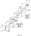
- Fig. 4 is a diagram illustrating an optical path in the optical path changing unit 2.
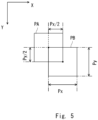
- Fig. 5 is a diagram illustrating a pixel display position in the pixel shift display.
- a configuration in which pixel shift display is performed using a birefringent element is used as in Patent Literature 2.
- Patent Literature 2 For the details of the pixel shift display, the same configuration and method as those of Patent Literature 2 can be used. Therefore, detailed description will not be repeated.
- the projection unit 111 which is an optical system of the projector 110 will be described with reference to Fig. 2 .
- the projection unit 111 includes the pixel shift display unit 1.
- the pixel shift display unit 1 is provided on an optical exit side of a color combination prism (cross dichroic prism) 18 that emits three pieces of red, green, and blue light incident from separate optical paths toward one optical path.
- a color combination prism cross dichroic prism
- the projection unit 111 includes a light source 11, and an integrator 12 and a polarized-light combination element 13 provided on a side on which light from the light source 11 travels.
- a high-pressure mercury lamp, a metal halide lamp, or the like is used as the light source 11.
- White light emitted from the light source 11 is reflected by a reflector 11a that has a rectilinear or paraboloid of revolution and is incident as substantially parallel light on the integrator 12.
- the integrator 12 spatially uniformizes intensity of the incident white light.
- the polarized-light combination element 13 is an optical element that includes a plurality of polarized beam splitters arranged in parallel in a strip form and configured in a flat shape and a phase difference plate, and aligns polarization directions of incident light polarized at random in a constant polarization direction and emits the light.
- the polarized-light combination element 13 converts incident light polarized at random into a P wave.
- the polarized-light combination element 13 may align the incident light to an S wave and subsequently convert the S wave into a P wave using a rotator (not illustrated).
- the projection unit 111 further includes a cross dichroic mirror 14.
- the cross dichroic mirror 14 separates white light from the polarized-light combination element 13 into light B containing a blue component and light Y containing a yellow component and causes the pieces of light to be emitted along separate optical paths.
- the blue light B passing through the cross dichroic mirror 14 is reflected by the dichroic mirror 15 and then is incident on a wire grid 16 serving as a polarized beam splitter (PBS).
- the dichroic mirror 15 may be a known mirror formed of an aluminum deposition film or the like.
- the wire grid 16 transmits the P wave and reflects the S wave. Since the light B from the cross dichroic mirror 14 is a P wave, the light B is transmitted through the wire grid 16 and is incident on a blue liquid crystal display element 17.
- the blue liquid crystal display element 17 reflects the incident light B toward the wire grid 16 while modulating a polarized component (that is, a P wave component) of the incident light B into the S wave according to the intensity of the blue component of a display image. For the light reflected from the blue liquid crystal display element 17, only the S wave component is reflected by the wire grid 16 and the light is incident on the color combination prism 18.
- the yellow light Y passing through the cross dichroic mirror 14 is incident on a dichroic mirror 20 via the dichroic mirror 19.
- the dichroic mirror 19 may be a known mirror formed of an aluminum deposition film or the like.
- the yellow light Y is separated into green light G and red light R, the green light G is reflected, and the red light R is transmitted.
- a green liquid crystal display element 22 and a wire grid 21 serving as a PBS, and a red liquid crystal display element 24 and a wire grid 23 serving as a PBS are provided respectively.
- the function is the same as that of the blue liquid crystal display element 17 and the wire grid 16 used for the light B. Accordingly, only the S wave component obtained through polarization modulation by the green liquid crystal display element 22 in the green light G is incident on the color combination prism 18. Only the S wave component obtained through polarization modulation by the red liquid crystal display element 24 in the red light R is incident on the color combination prism 18.
- the selection and disposition of each optical element to the color combination prism 18 are not limited to Fig. 1 and can be appropriately modified.
- the liquid crystal display elements 17, 22, and 24 are, for example, liquid crystal on silicon (LCOS) panels and a plurality of pixels are arranged in an array form.
- the liquid crystal display elements 17, 22, and 24 are spatial modulators that modulate and emit light based on pixel data.
- Each pixel of the liquid crystal display elements 17, 22, and 24 performs gradation display with a predetermined number of bits.
- each of the liquid crystal display elements 17, 22, and 24 has a resolution of 4K.
- Any of the liquid crystal display elements 17, 22, and 24 are not limited to a reflection type, but may be of a transmission type.
- the color combination prism 18 combines the light B, the light G, and the light R incident from each lateral surface and a rear surface and emit the light from the front surface.
- the light emitted from the color combination prism 18 is incident on a projection lens 7 serving as a projection optical system via the optical path changing unit 2 of the pixel shift display unit 1.
- the projection lens 7 projects incident illumination light toward the screen 114 (see Fig. 1 ) and forms an image to perform image display.
- the projection unit 111 can project a color image to the screen 114.
- the pixel shift display unit 1 includes the optical path changing unit 2 which is an optical element assembly, the projection lens 7, a polarization control driver 8, and a shutter control driver 9.
- the optical path changing unit 2 includes a half-wavelength plate 31, a polarization angle rotation element (a first polarization conversion element) 3, a birefringent element 4, a shutter element (a second polarization conversion element) 5, and a polarizer (polarization plate) 6 which are disposed in sequence from an incident side of light.
- the optical elements 3, 4, 5, and 6 may be configured as a layered structure or may be supported by a member formed of transparent glass or the like.
- the light from the color combination prism 18 is incident from the half-wavelength plate 31 and is emitted from the polarizer 6.
- the light from the polarizer 6 is incident on the projection lens 7 serving as a projection optical system.
- the half-wavelength plate 31 is installed so that an optical axis (a phase advance axis or a phase delay axis) T of the half-wavelength plate 31 is inclined at 22.5° around a traveling direction (that is, an optical axis) of the light with respect to the polarization direction of the incident light (the S wave) to rotate the polarization direction of light 27 of the incident S wave by 45°.
- the light emitted from the half-wavelength plate 31 is polarized rightward at 45° with respect to the polarization direction of the incident light when viewed in a direction oriented toward the polarizer 6 from the half-wavelength plate 31 as in Fig. 4 .
- the polarization angle rotation element 3 converts light polarized rightward at 45° into light polarized leftward at 45° by rotating a polarization angle (polarization direction) of the incident light by 90° around the optical axis.
- light polarized rightward at 45° is referred to as an R wave and light polarized leftward at 45° is referred to as an L wave.
- the conversion is performed based on an output voltage (an output signal) of the polarization control driver 8 whenever a display image in the liquid crystal display elements 17, 22, and 24 is updated.
- the polarization angle rotation element 3 can control polarization according to High/Low of a pulse signal output from the polarization control driver 8.
- a transmission-type liquid crystal panel configured using nematic liquid crystal or the like is used as an optical element that has such an optical rotation function.
- the birefringent element 4 is an optical element formed of a substance (for example, a crystal) causing birefringence and shifts an optical path at the time of emission according to a polarization direction of the incident R wave or L wave.
- the birefringent element 4 is also an optical lowpass filter (OLPF).
- OLPF optical lowpass filter
- the shutter element 5 has a similar configuration as the polarization angle rotation element 3 and converts the R wave into the L wave (or the L wave into the R wave) by rotating a polarization angle of incident light by 90° around the optical axis according to an application voltage by the shutter control driver 9.
- the shutter element 5 can control polarization according to High/Low of a pulse signal output from the shutter control driver 9.
- the polarizer 6 selects and emits only light in one polarization direction in light of two polarization directions set by the polarization angle rotation element 3 and discards light of the other polarization direction.
- the polarizer 6 may be of transmission type or reflection type.
- the polarizer 6 in the embodiment is, for example, a wire grid and is disposed so that only the R wave is passed and the L wave is blocked.
- the projection lens 7 expands and projects the light from the polarizer 6 to the screen 114.
- the projection lens 7 may be configured using a known lens. Therefore, detailed description will be omitted.
- a pixel display position is switched for each sub-frame image.
- a display position of a pixel on the screen 114 will be described with reference to Fig. 5.
- Fig. 5 schematically illustrates a display pixel position of one pixel.
- the horizontal direction of the screen 114 is an X direction and the vertical direction thereof is a Y direction.
- a pixel in the sub-frame image A is a pixel PA and a pixel in the sub-frame image B is a pixel PB.
- the pixels PA and PB are pixels that have the same pixel address.
- the position of the pixel PA is referred to as a first pixel display position and the position of the pixel PB is referred to as a second pixel display position.
- the pixels PA and PB are shifted by Px/2 in the X direction.
- the pixels PA and PB are shifted by Py/2 in the Y direction.
- Px is a pixel pitch in the X direction and Py is a pixel pitch in the Y direction. Accordingly, the pixel that has the same pixel address is projected to the first pixel display position in the sub-frame image A and is projected to the second pixel display position in the sub-frame pixel B. Accordingly, a display position (projection position) of the sub-frame image A and a display position (projection position) of the sub-frame image B are shifted by a half of a pixel.
- the polarization control driver 8 and the shutter control driver 9 generate pulse signals. Specifically, the polarization control driver 8 controls the polarization angle rotation element 3 so that the L wave is incident on the birefringent element 4 in the sub-frame image A and the R wave is incident on the birefringent element 4 in the sub-frame image B.
- the polarization control driver 8 may supply the polarization angle rotation element 3 with a pulse signal of which High and Low are switched at 120 Hz.
- the shutter control driver 9 may control the shutter element 5 so that the R wave is incident on the polarizer 6 when the sub-frame images are displayed. Specifically, for the sub-frame image A in which light of the L wave is incident on the birefringent element 4, the shutter element 5 converts the light from the L wave to the R wave. For the sub-frame B in which light of the R wave is incident on the birefringent element 4, the shutter element 5 causes the light to remain as the R wave. When the sub-frame images A and B are switches at 120 Hz, the shutter control driver 9 may supply the shutter element 5 with a pulse signal of which High and Low are switched at 120 Hz.
- each pixel is projected to the first pixel display position in the sub-frame image A and each pixel is projected to the second pixel display position in the sub-frame image B. That is, a projection position of a video on the screen 114 is switched at a predetermined period.
- a period in which the L wave is incident on the polarizer 6 may be provided. Thus, crosstalk can be suppressed.
- the optical path changing unit 2 shifts the optical path of the light from the liquid crystal display element according to a control signal so that the projection position by the projection lens 7 is switched at a predetermined period.
- the pixel shift display can be performed on a video projected by the projection lens 7.
- the optical path is changed using the birefringent element 4 to perform the pixel shift display.
- the optical path can also be changed using a piezoelectric actuator as in Patent Literature 1.
- the optical path may be changed for each sub-frame image according to another configuration.
- ON and OFF of the pixel shift display can be switched.
- the optical path changing unit 2 changes an optical path for each sub-frame image. That is, the optical path changing unit 2 changes an optical path so that the first pixel display position and the second pixel display position are alternately switched.
- the optical path changing unit 2 does not change the optical path. That is, the pixel display positions are normally the same position, for example, the normal first pixel display position.
- Fig. 6 is a block diagram illustrating a configuration of the video processing device 140.
- the video processing device 140 includes a determination unit 143, a control signal generation unit 145, a display image generation unit 146, an addition unit 147, and an output port 148.
- An original video is input to the determination unit 143 and the display image generation unit 146.
- the original video is, for example, a CG video generated by the video processing device 140 or a camera video acquired by a camera.
- a complete image may not be formed.
- a resolution of the original video is higher than a display resolution of the liquid crystal display elements 17, 22, and 24.
- the resolution of the original video is 8K and the display resolution of the liquid crystal display elements 17, 22, and 24 is 4K.
- a frame rate of the original video is, for example, 120 Hz. That is, a frame image of the original video is switched at each (1/120) sec. Of course, the frame rate is not limited to 120 Hz.
- the determination unit 143 determines whether to perform the pixel shift display based on the original video. When a motion of the original video is slower than a threshold, the determination unit 143 turns on the pixel shift display. When the motion is faster than the threshold, the determination unit 143 turns off the pixel shift display. For example, the determination unit 143 compares two or more continuous frame images of the original video. Then, when a motion between the adjacent frame images is small, the determination unit 143 turns on the pixel shift display. Conversely, when the motion between the adjacent frame images is large, the determination unit 143 turns off the pixel shift display.
- the determination unit 143 outputs a determination signal indicating a determination result to the control signal generation unit 145 and the display image generation unit 146.
- the determination unit 143 may perform determination based on a motion of an entire frame image or may perform determination according to a partial motion of a frame image or a motion of a target included in a frame image. Alternatively, the determination unit 143 may perform determination according to a motion other than the motion of the original video.
- the control signal generation unit 145 generates a control signal based on a determination result by the determination unit 143.
- the control signal includes an ON/OFF signal indicating ON/OFF of the pixel shift display and a High/Low signal indicating a pixel display position when the pixel shift display is turned on.
- the ON/OFF signal is 1-bit data. When a motion of the video is slow, the ON/OFF signal is a value indicating ON of the pixel shift display. When a motion of the video is fast, the ON/OFF signal is a value indicating OFF of the pixel shift display.
- the High/Low signal is 1-bit data. For example, when the pixel display position is the first pixel display position, the High/Low signal is a first value. When the pixel display position is the second pixel display position, the High/Low signal is a second value. When the pixel shift display is turned on, the first and second values are alternately repeated at a given period in the High/Low signal. When the pixel shift display is turned off, the High/Low signal is the same normal value. In this way, the control signal generation unit 145 generates a control signal with a total of 2 bits. The control signal generation unit 145 outputs the generated control signal to the addition unit 147.
- the display image generation unit 146 generates a display image from the original video based on a determination result by the determination unit 143.
- the display image corresponds to an image generated by the liquid crystal display elements 17, 22, and 24.
- the display image is configured using pixel data (RGB data) of each display pixel of the liquid crystal display elements 17, 22, and 24. For example, when the video processing device 140 acquires information regarding the liquid crystal display elements 17, 22, and 24 via the interface unit 130, a display resolution or the like can be understood.
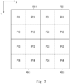
- Fig. 7 is a diagram illustrating pixels of the original video and display pixels in the liquid crystal display elements 17, 22, and 24.
- the liquid crystal display element 17 will be described as a representative of the liquid crystal display elements 17, 22, and 24.
- pixels P11 to P44 4x4 pixels in the original video are referred to as pixels P11 to P44.
- the pixels P11 to P44 correspond to 2x2 display pixels PD11 to PD22 of the liquid crystal display element 17. That is, four pixels of the original video correspond to one display pixel in the liquid crystal display element 17.
- a gradation value of the pixel P11 of the original video is referred to as a gradation value of the display pixel PD11.
- gradation values of the pixels P31, P13, and P33 of the original video are referred to as gradation values of the display pixels PD21, PD12, and PD22.
- gradation values of the pixels P22, P42, P24, and P44 are referred to as gradation values of the display pixels PD11, PD21, PD12, and PD22.
- the pixels P11 and P22 are displayed using the same display pixel PD11. That is, during a display period of the sub-frame image A (hereinafter referred to as a first display period), the gradation value of the display pixel PD11 of the liquid crystal display element 17 is the gradation value of the pixel P11. During a display period of the sub-frame image B (hereinafter referred to as a second display period), the gradation pixel of the display pixel PD11 of the liquid crystal display element 17 is the gradation value of the pixel P22.
- the two sub-frame images A and B can be generated from an image of one frame (original image) of the original video. That is, the gradation value of each pixel of the sub-frame images A and B can be determined from the gradation values of the original image.
- the sub-frame images A and B matched appropriately to the number of bits of the gradation values of the liquid crystal display element may be generated.
- the display image generation unit 146 when the pixel shift display is turned on, the display image generation unit 146 generates the sub-frame images A and B as display images from the original video.
- a method of generating the sub-frame images A and B is not limited to the foregoing method.
- the display image generation unit 146 may generate the sub-frame images A and B based on the original image in which two or more frames of the original video continue.
- a projected image of one frame is formed by the two sub-frame images A and B.
- the display image generation unit 146 when the motion of the video is fast, the pixel shift display is turned off.
- the display image generation unit 146 generates the display images from the original video according to another method.
- the display image generation unit 146 generates the display images of one frame from an image of one frame of the original video.
- a gradation value of the display pixel PD11 can be generated.
- the display image generation unit 146 sets an average value of the gradation values of the four pixels P11, P12, P21, and P22 to a gradation value of the display pixel PD11.
- the display image generation unit 146 sets a gradation value of one pixel among the four pixels P11, P12, P21, and P22 as a representative value to a gradation value of the display pixel PD11.
- the display images of one frame are generated from a frame image of one frame of the original video.
- the video processing device 140 is an IG
- the video processing device 140 can generate the original video with any resolution. Therefore, when the pixel shift display is turned off, the video processing device 140 may generate the original video with the same resolution as that of the display image.
- the display image generation unit 146 changes a scheme of generating a display video from the original video.
- the display image generation unit 146 generates the display images by using pixel data of a first pixel among n pixels in the display image in which a projection position is a first projection position and using pixel data of a second pixel among n pixels in the display image in which a projection position is a second projection position.
- the display image generation unit 146 When the determination unit 143 determines that the pixel shift display is not performed, the display image generation unit 146 generates the display images by using pixel data of one pixel among n pixels as a representative value or using an average value of the pixel data of the n pixels.
- n is not limited to 4 and may be 2 or more.
- the display image generation unit 146 generates the display images according to the resolution of the liquid crystal display element 17 based on the original video.
- the sub-frame images A and B when the pixel shift display is turned on are set as the display images.
- a projected image of one frame is formed by the two sub-frame images A and B.
- a projected image of one frame is formed by the display images of one frame when the pixel shift display is turned off.
- the display image generation unit 146 may generate the display images based on two or more continuous frame images of the original video.
- the display image generation unit 146 outputs the generated display images to the addition unit 147.
- the addition unit 147 adds the control signal to the display image.
- the control signal is 2-bit data.
- the addition unit 147 adds the control signal to pixel data (RGB data) of the display image.
- the addition unit 147 substitutes the first one pixel of the first line of the display image or a part of several pixels of the RGB data with the control signal.
- the addition unit 147 embeds the control signal which is a metadata in the display image.
- the addition unit 147 embeds the control signal on a low-bit side of the RGB data, an influence on the projected image can be reduced.
- the addition unit 147 embeds the control signal in the same bit of the same normal pixel address.
- the addition unit 147 is a display video signal generation unit that generates a display video signal by adding the control signal to the display image. That is, the addition unit 147 generates the display video signal in which the control signal is embedded as metadata in the RGB data.
- the display video signal generated by the addition unit 147 is transmitted to the interface unit 130 via the output port 148.
- the output port 148 is, for example, a DisplayPort.
- the video processing device 140 generates a display video signal including the display image and the control signal.
- the display video signal includes pixel data (RGB data) of the display image.
- a frame rate of the display image is 120 Hz and matches a frame rate of the liquid crystal display element 17.
- the liquid crystal display element 17 switches between the display images for each (1/120) sec.
- the RGB data of the display image is data indicating each gradation of the liquid crystal display elements 17, 22, and 24.
- the control signal includes the ON/OFF signal of the pixel shift display and the High/Low signal indicating polarity (a pixel display position) in the pixel shift display.
- the control signal is embedded in a part of the pixel data (the RGB data).
- Fig. 8 is a control block diagram illustrating a configuration of the projection unit 111.
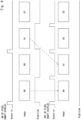
- Fig. 9 is a timing chart illustrating a process in the projector 110.
- the projection unit 111 includes an input port 121, a digital signal processor (DSP) 122, a decoder 123, a delay unit 124, a phase shift unit 125, and a switching unit 126.
- DSP digital signal processor
- the input port 121 is a DisplayPort.
- the display video signal from the video processing device 140 is input to the input port 121 via the interface unit 130.
- the display video signal from the input port 121 is input to the DSP 122 and the decoder 123.
- the DSP 122 generates a display driving signal of the liquid crystal display element 17 based on the display video signal.
- the display driving signal includes pixel data (RGB data) corresponding to a gradation value of each pixel.
- the DSP 122 outputs the display driving signal to the liquid crystal display element 17. Then, the liquid crystal display element 17 generates a display image based on pixel data (B data) of the display element.
- the liquid crystal display element 17 includes a display driver that drives a scanning line and a signal line based on the display driving signal. Accordingly, based on the pixel data of the display pixel, each pixel of the liquid crystal display element 17 realizes gradation display.
- the liquid crystal display elements 22 and 24 perform a similar process as the process of the liquid crystal display element 17, the liquid crystal display elements 22 and 24 are omitted in Fig. 8 .
- the liquid crystal display elements 22 and 24 perform gradation display based on G data and R data, respectively.
- the liquid crystal display elements 17, 22, and 24 modulate and emit light based on the pixel data (RGB data) of the display images included in the display video signal. Accordingly, the projection unit 111 can form a display image in which the RGB light is combined.
- the decoder 123 decodes the display image to extract the control signal. As described above, the control signal is embedded in the same bit of the same pixel address. Accordingly, the decoder 123 can extract the control signal embedded in the display image.
- the decoder 123 outputs an ON/OFF signal to the delay unit 124 and outputs a High/Low signal to the phase shift unit 125.
- the phase shift unit 125 shifts a phase of the High/Low signal and adjusts a timing of the High/Low signal for the display image. For example, according to a processing time in the DSP 122, the phase shift unit 125 shifts the phase of the High/Low signal by several clocks. Then, the phase shift unit 125 outputs the High/Low signal to the switching unit 126.
- the delay unit 124 adjusts the timings of the High/Low signal and the ON/OFF signal by delaying the ON/OFF signal by a predetermined time. The delay unit 124 outputs the ON/OFF signal to the switching unit 126 and the liquid crystal display element 17.
- the switching unit 126 serves as a control unit that controls the optical path changing unit 2 based on the ON/OFF signal and the High/Low signal.
- the switching unit 126 switches between ON and OFF of the pixel shift display based on the ON/OFF signal.
- the switching unit 126 controls the polarization control driver 8 and the shutter control driver 9 so that the optical path changing unit 2 switches the optical path at a period (120 Hz) corresponding to the sub-frame period.
- the sub-frame image A in which the display image is projected to the first display pixel position and the sub-frame image B in which the display image is projected to the second pixel display position are alternately switched.
- the switching unit 126 controls the polarization control driver 8 and the shutter control driver 9 so that the optical path changing unit 2 does not switch the optical path.
- the polarization control driver 8 and the shutter control driver 9 supply a given voltage to each of the polarization angle rotation element 3 and the shutter element 5. Thus, the display images are projected to the same normal position.
- a display frame rate of the display image is 120 Hz which is the same between ON and OFF of the pixel shift display. That is, the liquid crystal display element 17 switches between the display images at 120 Hz.
- the sub-frame image A and the sub-frame image B are alternately switched and displayed at 120 Hz.
- two sub-frame images A and B are generated as display images from one frame image of the original video.
- the video processing device 140 generates sub-frame images A0 and B0 from a frame image of frame number 0 of the original video.
- the video processing device 140 generates sub-frame images A1 and B1 from a frame image of frame number 1 of the original video.
- the High/Low signal is at H.
- the sub-frame images B0 and B1 the High/Low signal is at L.
- one display image is generated from one frame image of the original video.
- the video processing device 140 generates the display image A0 from the frame image of frame number 0 of the original video. Further, the video processing device 140 generates display images A1 to A3 from the frame images of frame numbers 1 to 3 of the original video.
- a frame rate of the original video is denoted by Vsync_in.
- Vsync_in a frame rate of the original video.
- the projection unit 111 turns off the pixel shift display. For example, when a target in the video is moving at a high speed, the video is displayed at a high frame rate. Thus, a motion of the target is displayed smoothly. On the other hand, in a scene in which a motion is slow, display delay does not occur even when the video is displayed at a low frame rate. Therefore, the projection unit 111 turns on the pixel shift display. Thus, in the scene in which the motion is slow, the image can be displayed with a high resolution. Thus, appropriate display can be performed according to a scene.
- the switching unit 126 may switch between ON and OFF of the pixel shift display for each frame. In this way, display can be dynamically switched according to a motion of the video. Alternatively, the switching unit 126 may switch between ON and OFF of the pixel shift display for each scene.
- the projection unit 111 can easily perform the pixel shift display. For example, when the pixel shift display is performed under external control, it is necessary for a CPU or the like to intervene. Therefore, it is difficult to perform control in which the ON/OFF of the pixel shift display and a speed of a motion of the video are matched in units of frames.
- the control signal is embedded in the pixel data, the ON/OFF of the pixel shift display and the speed of the motion of the video can be matched in units of frames. That is, it is possible to easily adjust a timing of the display switching.
- a frame rate when the determination unit 143 determines that the pixel shift display is performed is twice a frame rate at the same projection position (the same image display position) when the determination unit determines that the pixel shift display is not performed.
- the display image is alternately projected to the first pixel display position (the first projection position) and the second pixel display position (the second projection position).
- the display image is projected to the first pixel display position.
- a frame rate at the first pixel display position (the first projection position) when the pixel shift display is not performed is twice a frame rate at the first pixel display position (the first projection position) when the pixel shift display is performed.
- the frame rate at the first pixel display position is a frequency at which the display image is repeatedly projected to the first pixel display position (the first projection position).
- the frame rate of the display image projected to the first image display position is 120 Hz when the pixel shift display is turned off
- the frame rate of the display image projected to the first image display position is 60 Hz when the pixel shift display is turned on.
- the video processing device 140 When the video processing device 140 is an IG that generates a CG video, a resolution and a frame rate of the video can be changed arbitrarily.
- the video processing device 140 can change the resolution and the frame rate of the video according to a motion of the video.
- the video processing device 140 can generate a video at a high frame rate and a low resolution in a scene in which a motion is fast, and can generate a video at a low frame rate and a high resolution in a scene in which a motion is slow. Since the video processing device 140 may not generate a video at a high frame rate and a high resolution, a processing load of the video processing device 140 can be reduced.
- the video processing device 140 may generate a control signal according to performance (an imaging frame rate and an imaging resolution) of a camera. For example, the video processing device 140 generates a control signal so that the pixel shift display is turned on when a camera video is acquired at a resolution of 8K and a frame rate of 60 Hz, and the pixel shift display is turned off when a camera video is acquired at a resolution of 4K and a frame rate of 120 Hz. Thus, the camera video can be appropriately displayed.
- the foregoing resolution or frame rate is a general example and is not limited to the following value.
- the video processing device 140 generates a display image of 8K and 30P when the pixel shift display is turned on.
- the video processing device 140 generates a display image of 4K and 60P when the pixel shift display is turned off.
- a frame rate control process for example, see Japanese Unexamined Patent Application Publication No. 2012-93479 and Japanese Unexamined Patent Application Publication No. 2015-194596
- an error diffusion process for example, see Japanese Unexamined Patent Application Publication No. 2015-87631
- a frame rate control process is performed using a plurality of continuous frames as a set.
- a video signal when the pixel shift display is performed is a signal by which the sub-frames A and B are alternately repeated. Therefore, when the frame rate control process is performed on continuous (sub-) frames, a defect may occur. Accordingly, when the pixel shift display is performed, control is performed such that the frame rate control process is performed separately for each frame of the sub-frame A and each frame of the sub-frame B which are the same projection position.
- the ON/OFF signal input to the liquid crystal display element 17 is turned on (when the pixel shift display is performed)
- the frame rate control process is performed for every plurality of alternate frames.
- the ON/OF signal input to the liquid crystal display element 17 is turned off (when the pixel shift process is not performed)
- the frame rate control process is performed using a plurality of continuous frames as a set.
- control is performed such that the error diffusion process is similarly performed separately for each frame of the sub-frame A and each frame of the sub-frame B which are the same projection position when the pixel shift display is performed.
- the ON/OFF signal input to the liquid crystal display element 17 is turned on (when the pixel shift display is performed)
- the error diffusion process is performed for every plurality of alternate frames.
- the ON/OF signal input to the liquid crystal display element 17 is turned off (when the pixel shift process is not performed), the error diffusion process is performed using a plurality of continuous frames as a set.
- the optical path changing unit 2 may sequentially switch three or more pixel display positions.
- the optical path changing unit 2 may change the optical path so that four pixel display positions are sequentially switched.
- the first pixel display position is a reference
- the second pixel display position is shifted by 0.5 pixels in only the X direction
- a third pixel display position is shifted by 0.5 pixels in only the Y direction
- a fourth pixel display position is shifted by 0.5 pixels in the X and Y directions.
- the first pixel display position corresponds to the pixel P 11
- the second pixel display position corresponds to the pixel P21
- the third pixel display position corresponds to the pixel P12
- the fourth pixel display position corresponds to the pixel P22.
- the number of pixel display positions at the time of turning on the pixel shift display can also be changed step by step according to a speed of a motion of a video.
- the video processing device 140 can divide a motion of a video into three steps and switch between OFF of the pixel shift display, the pixel shift display at two pixel display positions, and pixel shift display at four display pixel positions.
- the video processing device 140 sets two thresholds for a motion of a video.
- a first threshold is a value indicating that a motion of the video is faster than that of a second threshold.
- the projection unit 111 turns off the pixel shift display.
- the projection unit 111 switches four pixel display positions and performs the pixel shift display.
- the projection unit 111 switches two pixel display positions and performs the pixel shift display.
- a control signal indicating the pixel display positions is 2-bit data.
- a frame rate of an original video can be changed step by step according to a motion of a video. Accordingly, display at a higher frame rate is possible in a video in which a motion is faster and a display at a lower frame rate is possible in a video in which a motion is slower. In this way, a processing load in the video processing device 140 can be reduced.
- control signal is used to switch between ON and OFF of the pixel shift display, but the control signal can also be used for other purposes.
- the video processing device 140 may generate the control signal in order to switch between two displays. Specifically, the video processing device 140 may generate a control signal for switching ON and OFF of 3D display. In this case, when the 3D display is turned on, the video processing device 140 alternately generates a left image and a right image as in the sub-frame images A and B. When the 3D display is turned off, the video processing device 140 generates a display image as in the time of turning off the pixel shift display. Thus, a 3-dimensional image can be displayed.
- the video processing device 140 may generate a control signal for switching between ON and OFF of infrared image display.
- the infrared image display When the infrared image display is turned on, an infrared image and a visible image are alternately generated as in the sub-frame images A and B.
- the video processing device 140 When the infrared image display is turned off, the video processing device 140 generates a display image as in the time of turning off the pixel shift display. Thus, the infrared image and the visible image can be alternately displayed.
- the pixel shift ON/OFF signal and the signal indicating the pixel display position in the case of the pixel shift ON have been described as different signals, but it is also realized an application in which these signals are used as one signal.
- Some or all of the foregoing processes may be performed by a computer program.
- the above-described program is stored using various types of non-transitory computer readable medium to be supplied to a computer.
- the non-transitory computer readable medium includes various types of tangible storage media.
- non-transitory computer readable medium examples include a magnetic recording medium (for example, a flexible disk, a magnetic tape, or a hard disk drive), a magneto-optical recording medium (for example, a magneto-optical disc), a CD-read-only memory (ROM), a CD-R, a CD-R/W, and a semiconductor memory (for example, a mask ROM or a programmable ROM (PROM), an erasable PROM (EPROM), and a flash ROM, and a random-access memory (RAM)).
- the program may be supplied to a computer by various types of transitory computer readable media. Examples of the transitory computer readable medium include an electrical signal, an optical signal, and an electromagnetic wave.
- a transitory computer readable medium can supply the program via a wired communication path such as an electrical wire or an optical fiber or a wireless communication path.
- the present disclosure can be applied to a video processing device and a display system displaying an image.
Landscapes
- Engineering & Computer Science (AREA)
- Physics & Mathematics (AREA)
- General Physics & Mathematics (AREA)
- Computer Hardware Design (AREA)
- Theoretical Computer Science (AREA)
- Chemical & Material Sciences (AREA)
- Crystallography & Structural Chemistry (AREA)
- Nonlinear Science (AREA)
- Signal Processing (AREA)
- Multimedia (AREA)
- Optics & Photonics (AREA)
- Mathematical Physics (AREA)
- Control Of Indicators Other Than Cathode Ray Tubes (AREA)
- Projection Apparatus (AREA)
- Liquid Crystal (AREA)
- Liquid Crystal Display Device Control (AREA)
- Transforming Electric Information Into Light Information (AREA)
Claims (7)
- Videoverarbeitungsvorrichtung (140), umfassend:eine Bestimmungseinheit (143), die dazu konfiguriert ist, ein Originalvideo zu empfangen und eine Bewegung zwischen benachbarten Bildern des Originalvideos zu bestimmen;eine Steuersignal-Erzeugungseinheit (145), die so konfiguriert ist, dass sie basierend auf einem Bestimmungsergebnis der Bestimmungseinheit ein Steuersignal erzeugt, wobei das Steuersignal ein erstes Signal und ein zweites Signal umfasst;eine Anzeigebild-Erzeugungseinheit (146), die so konfiguriert ist, dass sie das Originalvideo empfängt und auf der Grundlage des Bestimmungsergebnisses durch die Bestimmungseinheit ein Anzeigebild aus dem Originalvideo erzeugt; undeine Hinzufügungseinheit (147), die so konfiguriert ist, dass sie durch Hinzufügen des Steuersignals zum Anzeigebild ein Anzeigevideosignal erzeugt, wobei die Hinzufügungseinheit so konfiguriert ist, dass sie das erste Pixel der ersten Zeile des Anzeigebilds durch das Steuersignal ersetzt,wobeiwenn die Bewegung größer als ein vorgegebener Schwellenwert ist,die Bestimmungseinheit (143) bestimmt, die Pixelverschiebungsanzeige nicht durchzuführen,die Anzeigebild-Erzeugungseinheit (146) das Anzeigebild eines Einzelbildes aus einem Einzelbild des Originalvideos erzeugt, unddie Steuersignal-Erzeugungseinheit (145) das Steuersignal so erzeugt, dass das erste Signal AUS der Pixelverschiebungsanzeige anzeigt und das zweite Signal einen konstanten Wert hat, undwenn die Bewegung kleiner als der vorgegebene Schwellenwert ist,die Bestimmungseinheit (143) bestimmt, die Pixelverschiebungsanzeige durchzuführen,die Anzeigebild-Erzeugungseinheit (146) das Anzeigebild aus zwei Teilbildern aus einem Einzelbild des Originalvideos erzeugt, unddie Steuersignal-Erzeugungseinheit (145) das Steuersignal erzeugt, so dass das erste Signal EIN der Pixelverschiebungsanzeige anzeigt und ein erster Pixelanzeigepositionswert und ein zweiter Pixelanzeigepositionswert abwechselnd in einer gegebenen Periode im zweiten Signal wiederholt werden, wobei die ersten und zweiten Pixelanzeigepositionswerte verschoben werden, um jeweils die beiden um ein halbes Pixel verschobenen Teilbilder auf einen Bildschirm zu projizieren.
- Videoverarbeitungsvorrichtung nach Anspruch 1, wobei ein Anzeigepixel des Anzeigebildes n (wobei n eine ganze Zahl gleich oder größer als 2 ist) Pixel des Originalvideos entspricht,wenn die Bestimmungseinheit (143) entscheidet, die Pixelverschiebungsanzeige durchzuführen, die Anzeigebild-Erzeugungseinheit (146) das Anzeigebild unter Verwendung von Pixeldaten eines ersten Pixels unter den n Pixeln in einem Anzeigebild erzeugt, in dem das erste Signal der erste Wert ist und Pixeldaten eines zweiten Pixels unter den n Pixeln in einem Anzeigebild verwendet werden, bei dem das zweite Signal der zweite Wert ist, undwenn die Bestimmungseinheit (143) entscheidet, die Pixelverschiebungsanzeige nicht durchzuführen, die Anzeigebild-Erzeugungseinheit (146) das Anzeigebild unter Verwendung von Pixeldaten eines Pixels unter den n Pixeln als repräsentativem Wert oder unter Verwendung eines Durchschnittswerts von Pixeldaten der n Pixel erzeugt.
- Pixelverschiebungsanzeigevorrichtung, umfassend:einen Decoder;einen digitalen Signalprozessor, kurz DSP;einen Eingangsanschluss, der zum Empfang eines Anzeigevideosignals gemäß Anspruch 1 oder 2 konfiguriert ist, wobei der Eingangsanschluss mit dem Decoder und dem digitalen Signalprozessor verbunden ist;einen räumlichen Modulator (17, 22, 24), der zum Modulieren und Emittieren von Licht basierend auf Pixeldaten eines Anzeigetreibersignals konfiguriert ist, das vom DSP basierend auf dem Anzeigevideosignal erzeugt wird;ein optisches Projektionssystem, das so konfiguriert ist, dass es Licht vom räumlichen Modulator projiziert;eine Schalteinheit (126), die dazu konfiguriert ist, zwischen EIN und AUS einer Pixelverschiebungsanzeige basierend auf dem vom Decoder aus dem Anzeigevideosignal extrahierten Steuersignal umzuschalten; undeine optische Pfadänderungseinheit (7), die dazu konfiguriert ist, einen optischen Pfad des Lichts vom räumlichen Modulator zu verschieben, so dass eine Projektionsposition durch das optische Projektionssystem in der gegebenen Periode von der ersten Pixelanzeigeposition zur zweiten Pixelanzeigeposition umgeschaltet wird, wenn das Steuersignal EIN der Pixelverschiebungsanzeige anzeigt.
- Pixelverschiebungsanzeigevorrichtung nach Anspruch 3, wobeiwenn die Pixelverschiebungsanzeige nicht durchgeführt wird, die Projektionsposition des Anzeigebildes eine erste Projektionsposition ist,wenn die Pixelverschiebungsanzeige durchgeführt wird, die Projektionsposition abwechselnd zwischen der ersten Projektionsposition und einer zweiten Projektionsposition umgeschaltet wird, undeine Bildrate an der ersten Projektionsposition, wenn das Steuersignal AUS der Pixelverschiebungsanzeige anzeigt, doppelt so hoch ist wie eine Bildrate an der ersten Projektionsposition, wenn das Steuersignal EIN der Pixelverschiebungsanzeige anzeigt.
- Anzeigesystem, umfassend:eine Videoverarbeitungsvorrichtung nach Anspruch 1 oder 2, die so konfiguriert ist, dass sie aus dem Originalvideo ein Anzeigevideosignal erzeugt; undeine Pixelverschiebungsanzeigevorrichtung nach Anspruch 3 oder 4, die so konfiguriert ist, dass sie die Pixelverschiebungsanzeige basierend auf dem Anzeigevideosignal durchführt.
- Videoverarbeitungsverfahren, umfassend:einen Schritt zum Empfangen eines Originalvideos;einen Schritt zum Bestimmen einer Bewegung benachbarter Bilder des Originalvideos;einen Schritt zum Erzeugen eines Steuersignals basierend auf einem Bestimmungsergebnis, wobei das Steuersignal ein erstes Signal und ein zweites Signal umfasst;einen Schritt zum Erzeugen eines Anzeigebildes aus dem Originalvideo, basierend auf dem Bestimmungsergebnis; undeinen Schritt des Erzeugens eines Anzeigevideosignals durch Hinzufügen des Steuersignals zum Anzeigebild, wobei ein erstes Pixel der ersten Zeile des Anzeigebilds durch das Steuersignal ersetzt wird, wobei wenn die Bewegung größer als ein vorgegebener Schwellenwert ist,die Pixelverschiebungsanzeige nicht durchgeführt wird, das Anzeigebild aus einem Einzelbild aus einem Einzelbild des Originalvideos erzeugt wird, unddas Steuersignal erzeugt wird, so dass das erste Steuersignal AUS der Pixelverschiebungsanzeige anzeigt und das zweite Signal einen konstanten Wert hat, undwenn die Bewegung kleiner als der vorgegebene Schwellenwert ist,die Pixelverschiebungsanzeige durchgeführt wird,das Anzeigebild aus zwei Unterbildern aus einem Einzelbild des Originalvideos erzeugt wird, unddas Steuersignal erzeugt wird, so dass das erste Signal EIN der Pixelverschiebungsanzeige anzeigt und ein erster Pixelanzeigepositionswert und ein zweiter Pixelanzeigepositionswert abwechselnd in einer gegebenen Periode im zweiten Signal wiederholt werden,wobei die ersten und zweiten Pixelanzeigepositionswerte verschoben werden, um jeweils die beiden um ein halbes Pixel verschobenen Teilbilder auf einen Bildschirm zu projizieren.
- Computerprogrammprodukt, das Anweisungen umfasst, die, wenn das Programm von einem Computer ausgeführt wird, den Computer veranlassen, das Verfahren nach Anspruch 6 auszuführen.
Applications Claiming Priority (2)
| Application Number | Priority Date | Filing Date | Title |
|---|---|---|---|
| JP2017118954A JP6791034B2 (ja) | 2017-06-16 | 2017-06-16 | 表示システム、映像処理装置、画素ずらし表示装置、映像処理方法、表示方法、及びプログラム |
| PCT/JP2018/007244 WO2018230049A1 (ja) | 2017-06-16 | 2018-02-27 | 表示システム、映像処理装置、画素ずらし表示装置、映像処理方法、表示方法、及びプログラム |
Publications (3)
| Publication Number | Publication Date |
|---|---|
| EP3640933A1 EP3640933A1 (de) | 2020-04-22 |
| EP3640933A4 EP3640933A4 (de) | 2020-04-22 |
| EP3640933B1 true EP3640933B1 (de) | 2023-11-22 |
Family
ID=64660993
Family Applications (1)
| Application Number | Title | Priority Date | Filing Date |
|---|---|---|---|
| EP18818369.3A Active EP3640933B1 (de) | 2017-06-16 | 2018-02-27 | Anzeigesystem, videoverarbeitungsvorrichtung, pixelverschiebungsanzeigevorrichtung, videoverarbeitungsverfahren, anzeigeverfahren und programm |
Country Status (5)
| Country | Link |
|---|---|
| US (1) | US11381790B2 (de) |
| EP (1) | EP3640933B1 (de) |
| JP (1) | JP6791034B2 (de) |
| CN (1) | CN110770816B (de) |
| WO (1) | WO2018230049A1 (de) |
Families Citing this family (6)
| Publication number | Priority date | Publication date | Assignee | Title |
|---|---|---|---|---|
| CN112399157A (zh) * | 2019-08-15 | 2021-02-23 | 中强光电股份有限公司 | 投影机及投影方法 |
| US11716209B2 (en) * | 2020-04-14 | 2023-08-01 | The Regents Of The University Of Colorado, A Body Corporate | Systems and methods for azimuthal multiplexing three-dimensional diffractive optics |
| CN114079757A (zh) * | 2020-08-13 | 2022-02-22 | 深圳光峰科技股份有限公司 | 投影系统及投影设备 |
| EP4207009B1 (de) | 2020-12-24 | 2025-12-31 | Samsung Electronics Co., Ltd. | Elektronische vorrichtung und steuerungsverfahren dafür |
| EP4321908A4 (de) * | 2021-05-20 | 2024-10-09 | Samsung Electronics Co., Ltd. | Verfahren und vorrichtung zur luminanzsteuerung |
| JP7838334B2 (ja) * | 2022-03-15 | 2026-04-01 | セイコーエプソン株式会社 | プロジェクション装置およびプロジェクション装置の制御方法 |
Family Cites Families (41)
| Publication number | Priority date | Publication date | Assignee | Title |
|---|---|---|---|---|
| JPS5466238A (en) | 1977-11-02 | 1979-05-28 | Kojima Kiko | Seed germ in seed germ machine for *shiitake* sawdust and cover skriking in apparatus |
| US20020063807A1 (en) * | 1999-04-19 | 2002-05-30 | Neal Margulis | Method for Performing Image Transforms in a Digital Display System |
| JP2001157229A (ja) * | 1999-11-25 | 2001-06-08 | Olympus Optical Co Ltd | 映像表示装置 |
| KR100792283B1 (ko) * | 2001-08-07 | 2008-01-07 | 삼성전자주식회사 | 이동물체 자동 추적장치 및 방법 |
| MY139438A (en) * | 2004-05-06 | 2009-09-30 | Thomson Licensing Sa | Pixel shift display with minimal noise |
| JP2007110441A (ja) * | 2005-10-13 | 2007-04-26 | Fujifilm Corp | 撮像装置およびその処理方法 |
| JP2008139700A (ja) * | 2006-12-04 | 2008-06-19 | Ricoh Co Ltd | 画像表示装置 |
| JP2008271413A (ja) * | 2007-04-24 | 2008-11-06 | Olympus Corp | 画像表示装置、撮像装置、処理プログラム、画像表示装置の制御方法 |
| JP4418827B2 (ja) * | 2007-05-16 | 2010-02-24 | 三菱電機株式会社 | 画像表示装置及び方法、並びに画像発生装置及び方法 |
| US8913000B2 (en) * | 2007-06-15 | 2014-12-16 | Ricoh Co., Ltd. | Video playback on electronic paper displays |
| JP5298507B2 (ja) * | 2007-11-12 | 2013-09-25 | セイコーエプソン株式会社 | 画像表示装置及び画像表示方法 |
| JP4831081B2 (ja) * | 2008-01-22 | 2011-12-07 | ソニー株式会社 | 送信装置及びフレームレート変換システム |
| CN101667401B (zh) * | 2008-09-03 | 2013-01-09 | 奇美电子股份有限公司 | 液晶面板驱动方法及液晶显示器 |
| CN101808188B (zh) * | 2009-02-12 | 2012-08-08 | 瑞昱半导体股份有限公司 | 图像处理装置与图像处理方法 |
| JP5185202B2 (ja) * | 2009-06-03 | 2013-04-17 | キヤノン株式会社 | 画像処理装置及び画像処理装置の制御方法 |
| JP5569084B2 (ja) * | 2010-03-25 | 2014-08-13 | セイコーエプソン株式会社 | 画像表示装置および画像表示方法 |
| JP5538093B2 (ja) | 2010-06-29 | 2014-07-02 | 日本放送協会 | 画像表示装置および画像表示方法 |
| JP5375795B2 (ja) | 2010-10-26 | 2013-12-25 | 株式会社Jvcケンウッド | 液晶表示装置、液晶表示素子の駆動装置及び駆動方法 |
| CN103119640A (zh) * | 2010-09-27 | 2013-05-22 | Jvc建伍株式会社 | 液晶显示装置、液晶显示元件的驱动装置以及驱动方法 |
| CN103534744A (zh) * | 2011-02-25 | 2014-01-22 | 特里利特技术有限公司 | 具有移动元件的照明装置 |
| JP5772091B2 (ja) | 2011-03-11 | 2015-09-02 | 株式会社Jvcケンウッド | 画素ずらし表示装置、画素ずらし表示方法、画素ずらし表示装置を備える投射型表示装置 |
| CN102376236B (zh) * | 2011-09-16 | 2013-12-25 | 广东威创视讯科技股份有限公司 | 提高点阵显示屏分辨率的方法、装置及点阵显示屏系统 |
| JP5904754B2 (ja) * | 2011-10-17 | 2016-04-20 | キヤノン株式会社 | 情報処理システム、情報処理装置、それらの制御方法、およびプログラム |
| JP5862393B2 (ja) * | 2012-03-19 | 2016-02-16 | セイコーエプソン株式会社 | プロジェクター |
| JP6107007B2 (ja) * | 2012-09-06 | 2017-04-05 | セイコーエプソン株式会社 | プロジェクター |
| US20140085632A1 (en) * | 2012-09-24 | 2014-03-27 | Kyle Preston | Pixel-Shifting Spectrometer on Chip |
| EP3033877A4 (de) * | 2013-08-12 | 2017-07-12 | Intel Corporation | Verfahren für niederleistungs-videokompression und -übertragung |
| JP6197583B2 (ja) | 2013-10-31 | 2017-09-20 | 株式会社Jvcケンウッド | 液晶表示装置、駆動装置、及び駆動方法 |
| JP6331382B2 (ja) * | 2013-12-26 | 2018-05-30 | セイコーエプソン株式会社 | 画像表示装置、および画像表示装置の制御方法 |
| JP6364609B2 (ja) * | 2014-03-17 | 2018-08-01 | パナソニックIpマネジメント株式会社 | 投写型画像表示装置、及び画像信号生成装置 |
| JP6237415B2 (ja) | 2014-03-31 | 2017-11-29 | 株式会社Jvcケンウッド | 映像表示装置 |
| JP6415113B2 (ja) * | 2014-05-29 | 2018-10-31 | オリンパス株式会社 | 撮像装置、画像処理方法 |
| US9344696B2 (en) * | 2014-07-29 | 2016-05-17 | Texas Instruments Incorporated | Methods and apparatus for optical display using multiple spatial light modulators for increased resolution |
| CN104157229B (zh) * | 2014-07-30 | 2016-08-24 | 京东方科技集团股份有限公司 | 一种阵列基板的检测方法和设备 |
| EP3024231A1 (de) * | 2014-11-21 | 2016-05-25 | Thomson Licensing | Verfahren, Vorrichtung und System zur Korrektur von Fehlern stereoskopischer Displays |
| CN105988266A (zh) * | 2015-02-05 | 2016-10-05 | 深圳市绎立锐光科技开发有限公司 | 投影设备、投影控制系统及投影控制方法 |
| KR102689919B1 (ko) * | 2015-08-18 | 2024-07-30 | 매직 립, 인코포레이티드 | 가상 및 증강 현실 시스템들 및 방법들 |
| JP2017118954A (ja) | 2015-12-28 | 2017-07-06 | アンブローズアンドカンパニー株式会社 | 宝飾品の製造方法および宝飾品 |
| CN106507075A (zh) * | 2016-11-18 | 2017-03-15 | 海信集团有限公司 | 一种投影图像处理方法、装置及投影显示系统 |
| JP2018084686A (ja) * | 2016-11-24 | 2018-05-31 | 株式会社リコー | 画像投影装置および画像投影装置の制御方法 |
| JP6766662B2 (ja) * | 2017-01-25 | 2020-10-14 | 株式会社リコー | 画像処理装置、画像投影装置、および画像処理方法 |
-
2017
- 2017-06-16 JP JP2017118954A patent/JP6791034B2/ja active Active
-
2018
- 2018-02-27 CN CN201880039907.5A patent/CN110770816B/zh active Active
- 2018-02-27 WO PCT/JP2018/007244 patent/WO2018230049A1/ja not_active Ceased
- 2018-02-27 EP EP18818369.3A patent/EP3640933B1/de active Active
-
2019
- 2019-12-13 US US16/714,458 patent/US11381790B2/en active Active
Also Published As
| Publication number | Publication date |
|---|---|
| WO2018230049A1 (ja) | 2018-12-20 |
| CN110770816A (zh) | 2020-02-07 |
| US11381790B2 (en) | 2022-07-05 |
| JP2019003108A (ja) | 2019-01-10 |
| EP3640933A1 (de) | 2020-04-22 |
| CN110770816B (zh) | 2022-06-14 |
| EP3640933A4 (de) | 2020-04-22 |
| JP6791034B2 (ja) | 2020-11-25 |
| US20200120316A1 (en) | 2020-04-16 |
Similar Documents
| Publication | Publication Date | Title |
|---|---|---|
| EP3640933B1 (de) | Anzeigesystem, videoverarbeitungsvorrichtung, pixelverschiebungsanzeigevorrichtung, videoverarbeitungsverfahren, anzeigeverfahren und programm | |
| US10205923B2 (en) | Apparatus and method for processing a projected image, and projection display system | |
| JP7053103B2 (ja) | 投影システムおよび方法 | |
| US9022582B2 (en) | High dynamic range projection system | |
| JP7309360B2 (ja) | 画像投射装置およびその制御方法 | |
| CN114374828B (zh) | 显示设备、显示系统及显示方法 | |
| US6984040B2 (en) | Synchronizing periodic variation of a plurality of colors of light and projection of a plurality of sub-frame images | |
| EP3845964B1 (de) | Beleuchtungsvorrichtung und anzeigevorrichtung | |
| US10070106B2 (en) | Optical system designs for generation of light fields using spatial light modulators | |
| US7154508B2 (en) | Displaying least significant color image bit-planes in less than all image sub-frame locations | |
| CN108663883A (zh) | 一种投影显示系统 | |
| JP2005208646A (ja) | シーケンシャルカラーデバイスおよび揺動装置を備えた表示システム | |
| US10880527B2 (en) | Video display device | |
| JP2010175907A (ja) | 投射型表示装置及びその表示方法 | |
| EP2963493B1 (de) | Bildprojektionsvorrichtung | |
| JP2022091477A (ja) | 画像投射装置、画像投射装置の制御方法、及びプログラム | |
| KR101453451B1 (ko) | 위상지연 방식을 이용한 고휘도 입체영상상영장치 및 이를 구동하는 방법 | |
| JP7354801B2 (ja) | 表示装置、表示装置の制御方法 | |
| CN113039484A (zh) | 图像显示装置 | |
| JP2010096932A (ja) | 画像表示方法、画像表示装置および画像表示プログラム | |
| Kupiec et al. | Multiview multiperspective time multiplexed autostereoscopic display | |
| JP2004151649A (ja) | プロジェクタ | |
| JP2008090239A (ja) | 投射型画像表示装置 | |
| CN120416444A (zh) | 激光投影设备、控制方法及控制装置 | |
| JP2009086163A (ja) | 画像表示装置 |
Legal Events
| Date | Code | Title | Description |
|---|---|---|---|
| STAA | Information on the status of an ep patent application or granted ep patent |
Free format text: STATUS: THE INTERNATIONAL PUBLICATION HAS BEEN MADE |
|
| PUAI | Public reference made under article 153(3) epc to a published international application that has entered the european phase |
Free format text: ORIGINAL CODE: 0009012 |
|
| STAA | Information on the status of an ep patent application or granted ep patent |
Free format text: STATUS: REQUEST FOR EXAMINATION WAS MADE |
|
| 17P | Request for examination filed |
Effective date: 20191212 |
|
| A4 | Supplementary search report drawn up and despatched |
Effective date: 20200323 |
|
| AK | Designated contracting states |
Kind code of ref document: A1 Designated state(s): AL AT BE BG CH CY CZ DE DK EE ES FI FR GB GR HR HU IE IS IT LI LT LU LV MC MK MT NL NO PL PT RO RS SE SI SK SM TR |
|
| AX | Request for extension of the european patent |
Extension state: BA ME |
|
| DAV | Request for validation of the european patent (deleted) | ||
| DAX | Request for extension of the european patent (deleted) | ||
| STAA | Information on the status of an ep patent application or granted ep patent |
Free format text: STATUS: EXAMINATION IS IN PROGRESS |
|
| 17Q | First examination report despatched |
Effective date: 20211119 |
|
| GRAP | Despatch of communication of intention to grant a patent |
Free format text: ORIGINAL CODE: EPIDOSNIGR1 |
|
| STAA | Information on the status of an ep patent application or granted ep patent |
Free format text: STATUS: GRANT OF PATENT IS INTENDED |
|
| INTG | Intention to grant announced |
Effective date: 20230718 |
|
| GRAS | Grant fee paid |
Free format text: ORIGINAL CODE: EPIDOSNIGR3 |
|
| GRAA | (expected) grant |
Free format text: ORIGINAL CODE: 0009210 |
|
| STAA | Information on the status of an ep patent application or granted ep patent |
Free format text: STATUS: THE PATENT HAS BEEN GRANTED |
|
| AK | Designated contracting states |
Kind code of ref document: B1 Designated state(s): AL AT BE BG CH CY CZ DE DK EE ES FI FR GB GR HR HU IE IS IT LI LT LU LV MC MK MT NL NO PL PT RO RS SE SI SK SM TR |
|
| REG | Reference to a national code |
Ref country code: GB Ref legal event code: FG4D |
|
| REG | Reference to a national code |
Ref country code: CH Ref legal event code: EP |
|
| REG | Reference to a national code |
Ref country code: DE Ref legal event code: R096 Ref document number: 602018061529 Country of ref document: DE |
|
| REG | Reference to a national code |
Ref country code: IE Ref legal event code: FG4D |
|
| REG | Reference to a national code |
Ref country code: LT Ref legal event code: MG9D |
|
| REG | Reference to a national code |
Ref country code: NL Ref legal event code: MP Effective date: 20231122 |
|
| PG25 | Lapsed in a contracting state [announced via postgrant information from national office to epo] |
Ref country code: GR Free format text: LAPSE BECAUSE OF FAILURE TO SUBMIT A TRANSLATION OF THE DESCRIPTION OR TO PAY THE FEE WITHIN THE PRESCRIBED TIME-LIMIT Effective date: 20240223 |
|
| PG25 | Lapsed in a contracting state [announced via postgrant information from national office to epo] |
Ref country code: IS Free format text: LAPSE BECAUSE OF FAILURE TO SUBMIT A TRANSLATION OF THE DESCRIPTION OR TO PAY THE FEE WITHIN THE PRESCRIBED TIME-LIMIT Effective date: 20240322 |
|
| PG25 | Lapsed in a contracting state [announced via postgrant information from national office to epo] |
Ref country code: LT Free format text: LAPSE BECAUSE OF FAILURE TO SUBMIT A TRANSLATION OF THE DESCRIPTION OR TO PAY THE FEE WITHIN THE PRESCRIBED TIME-LIMIT Effective date: 20231122 |
|
| REG | Reference to a national code |
Ref country code: AT Ref legal event code: MK05 Ref document number: 1634585 Country of ref document: AT Kind code of ref document: T Effective date: 20231122 |
|
| PG25 | Lapsed in a contracting state [announced via postgrant information from national office to epo] |
Ref country code: NL Free format text: LAPSE BECAUSE OF FAILURE TO SUBMIT A TRANSLATION OF THE DESCRIPTION OR TO PAY THE FEE WITHIN THE PRESCRIBED TIME-LIMIT Effective date: 20231122 |
|
| PG25 | Lapsed in a contracting state [announced via postgrant information from national office to epo] |
Ref country code: AT Free format text: LAPSE BECAUSE OF FAILURE TO SUBMIT A TRANSLATION OF THE DESCRIPTION OR TO PAY THE FEE WITHIN THE PRESCRIBED TIME-LIMIT Effective date: 20231122 |
|
| PG25 | Lapsed in a contracting state [announced via postgrant information from national office to epo] |
Ref country code: ES Free format text: LAPSE BECAUSE OF FAILURE TO SUBMIT A TRANSLATION OF THE DESCRIPTION OR TO PAY THE FEE WITHIN THE PRESCRIBED TIME-LIMIT Effective date: 20231122 |
|
| PG25 | Lapsed in a contracting state [announced via postgrant information from national office to epo] |
Ref country code: NL Free format text: LAPSE BECAUSE OF FAILURE TO SUBMIT A TRANSLATION OF THE DESCRIPTION OR TO PAY THE FEE WITHIN THE PRESCRIBED TIME-LIMIT Effective date: 20231122 Ref country code: LT Free format text: LAPSE BECAUSE OF FAILURE TO SUBMIT A TRANSLATION OF THE DESCRIPTION OR TO PAY THE FEE WITHIN THE PRESCRIBED TIME-LIMIT Effective date: 20231122 Ref country code: IS Free format text: LAPSE BECAUSE OF FAILURE TO SUBMIT A TRANSLATION OF THE DESCRIPTION OR TO PAY THE FEE WITHIN THE PRESCRIBED TIME-LIMIT Effective date: 20240322 Ref country code: GR Free format text: LAPSE BECAUSE OF FAILURE TO SUBMIT A TRANSLATION OF THE DESCRIPTION OR TO PAY THE FEE WITHIN THE PRESCRIBED TIME-LIMIT Effective date: 20240223 Ref country code: ES Free format text: LAPSE BECAUSE OF FAILURE TO SUBMIT A TRANSLATION OF THE DESCRIPTION OR TO PAY THE FEE WITHIN THE PRESCRIBED TIME-LIMIT Effective date: 20231122 Ref country code: BG Free format text: LAPSE BECAUSE OF FAILURE TO SUBMIT A TRANSLATION OF THE DESCRIPTION OR TO PAY THE FEE WITHIN THE PRESCRIBED TIME-LIMIT Effective date: 20240222 Ref country code: AT Free format text: LAPSE BECAUSE OF FAILURE TO SUBMIT A TRANSLATION OF THE DESCRIPTION OR TO PAY THE FEE WITHIN THE PRESCRIBED TIME-LIMIT Effective date: 20231122 Ref country code: PT Free format text: LAPSE BECAUSE OF FAILURE TO SUBMIT A TRANSLATION OF THE DESCRIPTION OR TO PAY THE FEE WITHIN THE PRESCRIBED TIME-LIMIT Effective date: 20240322 |
|
| PG25 | Lapsed in a contracting state [announced via postgrant information from national office to epo] |
Ref country code: SE Free format text: LAPSE BECAUSE OF FAILURE TO SUBMIT A TRANSLATION OF THE DESCRIPTION OR TO PAY THE FEE WITHIN THE PRESCRIBED TIME-LIMIT Effective date: 20231122 Ref country code: RS Free format text: LAPSE BECAUSE OF FAILURE TO SUBMIT A TRANSLATION OF THE DESCRIPTION OR TO PAY THE FEE WITHIN THE PRESCRIBED TIME-LIMIT Effective date: 20231122 Ref country code: PL Free format text: LAPSE BECAUSE OF FAILURE TO SUBMIT A TRANSLATION OF THE DESCRIPTION OR TO PAY THE FEE WITHIN THE PRESCRIBED TIME-LIMIT Effective date: 20231122 Ref country code: NO Free format text: LAPSE BECAUSE OF FAILURE TO SUBMIT A TRANSLATION OF THE DESCRIPTION OR TO PAY THE FEE WITHIN THE PRESCRIBED TIME-LIMIT Effective date: 20240222 Ref country code: LV Free format text: LAPSE BECAUSE OF FAILURE TO SUBMIT A TRANSLATION OF THE DESCRIPTION OR TO PAY THE FEE WITHIN THE PRESCRIBED TIME-LIMIT Effective date: 20231122 Ref country code: HR Free format text: LAPSE BECAUSE OF FAILURE TO SUBMIT A TRANSLATION OF THE DESCRIPTION OR TO PAY THE FEE WITHIN THE PRESCRIBED TIME-LIMIT Effective date: 20231122 |
|
| PG25 | Lapsed in a contracting state [announced via postgrant information from national office to epo] |
Ref country code: DK Free format text: LAPSE BECAUSE OF FAILURE TO SUBMIT A TRANSLATION OF THE DESCRIPTION OR TO PAY THE FEE WITHIN THE PRESCRIBED TIME-LIMIT Effective date: 20231122 |
|
| PG25 | Lapsed in a contracting state [announced via postgrant information from national office to epo] |
Ref country code: CZ Free format text: LAPSE BECAUSE OF FAILURE TO SUBMIT A TRANSLATION OF THE DESCRIPTION OR TO PAY THE FEE WITHIN THE PRESCRIBED TIME-LIMIT Effective date: 20231122 |
|
| PG25 | Lapsed in a contracting state [announced via postgrant information from national office to epo] |
Ref country code: SK Free format text: LAPSE BECAUSE OF FAILURE TO SUBMIT A TRANSLATION OF THE DESCRIPTION OR TO PAY THE FEE WITHIN THE PRESCRIBED TIME-LIMIT Effective date: 20231122 |
|
| PG25 | Lapsed in a contracting state [announced via postgrant information from national office to epo] |
Ref country code: SM Free format text: LAPSE BECAUSE OF FAILURE TO SUBMIT A TRANSLATION OF THE DESCRIPTION OR TO PAY THE FEE WITHIN THE PRESCRIBED TIME-LIMIT Effective date: 20231122 Ref country code: SK Free format text: LAPSE BECAUSE OF FAILURE TO SUBMIT A TRANSLATION OF THE DESCRIPTION OR TO PAY THE FEE WITHIN THE PRESCRIBED TIME-LIMIT Effective date: 20231122 Ref country code: RO Free format text: LAPSE BECAUSE OF FAILURE TO SUBMIT A TRANSLATION OF THE DESCRIPTION OR TO PAY THE FEE WITHIN THE PRESCRIBED TIME-LIMIT Effective date: 20231122 Ref country code: IT Free format text: LAPSE BECAUSE OF FAILURE TO SUBMIT A TRANSLATION OF THE DESCRIPTION OR TO PAY THE FEE WITHIN THE PRESCRIBED TIME-LIMIT Effective date: 20231122 Ref country code: EE Free format text: LAPSE BECAUSE OF FAILURE TO SUBMIT A TRANSLATION OF THE DESCRIPTION OR TO PAY THE FEE WITHIN THE PRESCRIBED TIME-LIMIT Effective date: 20231122 Ref country code: DK Free format text: LAPSE BECAUSE OF FAILURE TO SUBMIT A TRANSLATION OF THE DESCRIPTION OR TO PAY THE FEE WITHIN THE PRESCRIBED TIME-LIMIT Effective date: 20231122 Ref country code: CZ Free format text: LAPSE BECAUSE OF FAILURE TO SUBMIT A TRANSLATION OF THE DESCRIPTION OR TO PAY THE FEE WITHIN THE PRESCRIBED TIME-LIMIT Effective date: 20231122 |
|
| REG | Reference to a national code |
Ref country code: DE Ref legal event code: R097 Ref document number: 602018061529 Country of ref document: DE |
|
| PLBE | No opposition filed within time limit |
Free format text: ORIGINAL CODE: 0009261 |
|
| STAA | Information on the status of an ep patent application or granted ep patent |
Free format text: STATUS: NO OPPOSITION FILED WITHIN TIME LIMIT |
|
| PG25 | Lapsed in a contracting state [announced via postgrant information from national office to epo] |
Ref country code: MC Free format text: LAPSE BECAUSE OF FAILURE TO SUBMIT A TRANSLATION OF THE DESCRIPTION OR TO PAY THE FEE WITHIN THE PRESCRIBED TIME-LIMIT Effective date: 20231122 |
|
| REG | Reference to a national code |
Ref country code: CH Ref legal event code: PL |
|
| PG25 | Lapsed in a contracting state [announced via postgrant information from national office to epo] |
Ref country code: LU Free format text: LAPSE BECAUSE OF NON-PAYMENT OF DUE FEES Effective date: 20240227 |
|
| PG25 | Lapsed in a contracting state [announced via postgrant information from national office to epo] |
Ref country code: CH Free format text: LAPSE BECAUSE OF NON-PAYMENT OF DUE FEES Effective date: 20240229 |
|
| PG25 | Lapsed in a contracting state [announced via postgrant information from national office to epo] |
Ref country code: SI Free format text: LAPSE BECAUSE OF FAILURE TO SUBMIT A TRANSLATION OF THE DESCRIPTION OR TO PAY THE FEE WITHIN THE PRESCRIBED TIME-LIMIT Effective date: 20231122 |
|
| 26N | No opposition filed |
Effective date: 20240823 |
|
| PG25 | Lapsed in a contracting state [announced via postgrant information from national office to epo] |
Ref country code: SI Free format text: LAPSE BECAUSE OF FAILURE TO SUBMIT A TRANSLATION OF THE DESCRIPTION OR TO PAY THE FEE WITHIN THE PRESCRIBED TIME-LIMIT Effective date: 20231122 Ref country code: LU Free format text: LAPSE BECAUSE OF NON-PAYMENT OF DUE FEES Effective date: 20240227 Ref country code: CH Free format text: LAPSE BECAUSE OF NON-PAYMENT OF DUE FEES Effective date: 20240229 |
|
| REG | Reference to a national code |
Ref country code: BE Ref legal event code: MM Effective date: 20240229 |
|
| PG25 | Lapsed in a contracting state [announced via postgrant information from national office to epo] |
Ref country code: BE Free format text: LAPSE BECAUSE OF NON-PAYMENT OF DUE FEES Effective date: 20240229 |
|
| PG25 | Lapsed in a contracting state [announced via postgrant information from national office to epo] |
Ref country code: FR Free format text: LAPSE BECAUSE OF NON-PAYMENT OF DUE FEES Effective date: 20240229 |
|
| PG25 | Lapsed in a contracting state [announced via postgrant information from national office to epo] |
Ref country code: IE Free format text: LAPSE BECAUSE OF NON-PAYMENT OF DUE FEES Effective date: 20240227 |
|
| PG25 | Lapsed in a contracting state [announced via postgrant information from national office to epo] |
Ref country code: IE Free format text: LAPSE BECAUSE OF NON-PAYMENT OF DUE FEES Effective date: 20240227 Ref country code: FR Free format text: LAPSE BECAUSE OF NON-PAYMENT OF DUE FEES Effective date: 20240229 Ref country code: BE Free format text: LAPSE BECAUSE OF NON-PAYMENT OF DUE FEES Effective date: 20240229 |
|
| PG25 | Lapsed in a contracting state [announced via postgrant information from national office to epo] |
Ref country code: CY Free format text: LAPSE BECAUSE OF FAILURE TO SUBMIT A TRANSLATION OF THE DESCRIPTION OR TO PAY THE FEE WITHIN THE PRESCRIBED TIME-LIMIT; INVALID AB INITIO Effective date: 20180227 |
|
| PG25 | Lapsed in a contracting state [announced via postgrant information from national office to epo] |
Ref country code: HU Free format text: LAPSE BECAUSE OF FAILURE TO SUBMIT A TRANSLATION OF THE DESCRIPTION OR TO PAY THE FEE WITHIN THE PRESCRIBED TIME-LIMIT; INVALID AB INITIO Effective date: 20180227 |
|
| PG25 | Lapsed in a contracting state [announced via postgrant information from national office to epo] |
Ref country code: FI Free format text: LAPSE BECAUSE OF FAILURE TO SUBMIT A TRANSLATION OF THE DESCRIPTION OR TO PAY THE FEE WITHIN THE PRESCRIBED TIME-LIMIT Effective date: 20231122 |
|
| PG25 | Lapsed in a contracting state [announced via postgrant information from national office to epo] |
Ref country code: TR Free format text: LAPSE BECAUSE OF FAILURE TO SUBMIT A TRANSLATION OF THE DESCRIPTION OR TO PAY THE FEE WITHIN THE PRESCRIBED TIME-LIMIT Effective date: 20231122 |
|
| PGFP | Annual fee paid to national office [announced via postgrant information from national office to epo] |
Ref country code: GB Payment date: 20260106 Year of fee payment: 9 |
|
| PGFP | Annual fee paid to national office [announced via postgrant information from national office to epo] |
Ref country code: DE Payment date: 20260102 Year of fee payment: 9 |