EP3640675B1 - Schätzung des winkels eines menschlichen zieles unter verwendung von millimeterwellenradar - Google Patents
Schätzung des winkels eines menschlichen zieles unter verwendung von millimeterwellenradar Download PDFInfo
- Publication number
- EP3640675B1 EP3640675B1 EP19203217.5A EP19203217A EP3640675B1 EP 3640675 B1 EP3640675 B1 EP 3640675B1 EP 19203217 A EP19203217 A EP 19203217A EP 3640675 B1 EP3640675 B1 EP 3640675B1
- Authority
- EP
- European Patent Office
- Prior art keywords
- range
- doppler
- target
- angle
- arrival
- Prior art date
- Legal status (The legal status is an assumption and is not a legal conclusion. Google has not performed a legal analysis and makes no representation as to the accuracy of the status listed.)
- Active
Links
- 238000000034 method Methods 0.000 claims description 57
- 238000001228 spectrum Methods 0.000 claims description 33
- 230000029058 respiratory gaseous exchange Effects 0.000 claims description 6
- 230000001131 transforming effect Effects 0.000 claims description 2
- 230000035565 breathing frequency Effects 0.000 claims 1
- 241000282412 Homo Species 0.000 description 25
- 230000003068 static effect Effects 0.000 description 16
- 230000000875 corresponding effect Effects 0.000 description 15
- 230000006870 function Effects 0.000 description 8
- 230000033001 locomotion Effects 0.000 description 7
- 239000013598 vector Substances 0.000 description 6
- 230000001427 coherent effect Effects 0.000 description 5
- 230000001747 exhibiting effect Effects 0.000 description 4
- 230000010354 integration Effects 0.000 description 3
- 230000005855 radiation Effects 0.000 description 3
- 239000004065 semiconductor Substances 0.000 description 3
- 229910000577 Silicon-germanium Inorganic materials 0.000 description 2
- 230000008859 change Effects 0.000 description 2
- 230000000694 effects Effects 0.000 description 2
- 238000001914 filtration Methods 0.000 description 2
- 239000000463 material Substances 0.000 description 2
- 229910044991 metal oxide Inorganic materials 0.000 description 2
- 150000004706 metal oxides Chemical class 0.000 description 2
- NCGICGYLBXGBGN-UHFFFAOYSA-N 3-morpholin-4-yl-1-oxa-3-azonia-2-azanidacyclopent-3-en-5-imine;hydrochloride Chemical compound Cl.[N-]1OC(=N)C=[N+]1N1CCOCC1 NCGICGYLBXGBGN-UHFFFAOYSA-N 0.000 description 1
- LEVVHYCKPQWKOP-UHFFFAOYSA-N [Si].[Ge] Chemical compound [Si].[Ge] LEVVHYCKPQWKOP-UHFFFAOYSA-N 0.000 description 1
- 230000004931 aggregating effect Effects 0.000 description 1
- 238000004458 analytical method Methods 0.000 description 1
- 230000005540 biological transmission Effects 0.000 description 1
- 230000015572 biosynthetic process Effects 0.000 description 1
- 238000004891 communication Methods 0.000 description 1
- 230000000295 complement effect Effects 0.000 description 1
- 230000002596 correlated effect Effects 0.000 description 1
- 238000001514 detection method Methods 0.000 description 1
- 238000006073 displacement reaction Methods 0.000 description 1
- 238000005516 engineering process Methods 0.000 description 1
- 238000005755 formation reaction Methods 0.000 description 1
- 230000006872 improvement Effects 0.000 description 1
- 230000000737 periodic effect Effects 0.000 description 1
- 230000008569 process Effects 0.000 description 1
- 230000036387 respiratory rate Effects 0.000 description 1
- 238000010845 search algorithm Methods 0.000 description 1
- 210000000779 thoracic wall Anatomy 0.000 description 1
Images


Classifications
-
- G—PHYSICS
- G01—MEASURING; TESTING
- G01S—RADIO DIRECTION-FINDING; RADIO NAVIGATION; DETERMINING DISTANCE OR VELOCITY BY USE OF RADIO WAVES; LOCATING OR PRESENCE-DETECTING BY USE OF THE REFLECTION OR RERADIATION OF RADIO WAVES; ANALOGOUS ARRANGEMENTS USING OTHER WAVES
- G01S13/00—Systems using the reflection or reradiation of radio waves, e.g. radar systems; Analogous systems using reflection or reradiation of waves whose nature or wavelength is irrelevant or unspecified
- G01S13/02—Systems using reflection of radio waves, e.g. primary radar systems; Analogous systems
- G01S13/06—Systems determining position data of a target
- G01S13/08—Systems for measuring distance only
- G01S13/10—Systems for measuring distance only using transmission of interrupted, pulse modulated waves
- G01S13/26—Systems for measuring distance only using transmission of interrupted, pulse modulated waves wherein the transmitted pulses use a frequency- or phase-modulated carrier wave
-
- G—PHYSICS
- G01—MEASURING; TESTING
- G01S—RADIO DIRECTION-FINDING; RADIO NAVIGATION; DETERMINING DISTANCE OR VELOCITY BY USE OF RADIO WAVES; LOCATING OR PRESENCE-DETECTING BY USE OF THE REFLECTION OR RERADIATION OF RADIO WAVES; ANALOGOUS ARRANGEMENTS USING OTHER WAVES
- G01S13/00—Systems using the reflection or reradiation of radio waves, e.g. radar systems; Analogous systems using reflection or reradiation of waves whose nature or wavelength is irrelevant or unspecified
- G01S13/02—Systems using reflection of radio waves, e.g. primary radar systems; Analogous systems
- G01S13/50—Systems of measurement based on relative movement of target
- G01S13/58—Velocity or trajectory determination systems; Sense-of-movement determination systems
- G01S13/583—Velocity or trajectory determination systems; Sense-of-movement determination systems using transmission of continuous unmodulated waves, amplitude-, frequency-, or phase-modulated waves and based upon the Doppler effect resulting from movement of targets
- G01S13/584—Velocity or trajectory determination systems; Sense-of-movement determination systems using transmission of continuous unmodulated waves, amplitude-, frequency-, or phase-modulated waves and based upon the Doppler effect resulting from movement of targets adapted for simultaneous range and velocity measurements
-
- G—PHYSICS
- G01—MEASURING; TESTING
- G01S—RADIO DIRECTION-FINDING; RADIO NAVIGATION; DETERMINING DISTANCE OR VELOCITY BY USE OF RADIO WAVES; LOCATING OR PRESENCE-DETECTING BY USE OF THE REFLECTION OR RERADIATION OF RADIO WAVES; ANALOGOUS ARRANGEMENTS USING OTHER WAVES
- G01S13/00—Systems using the reflection or reradiation of radio waves, e.g. radar systems; Analogous systems using reflection or reradiation of waves whose nature or wavelength is irrelevant or unspecified
- G01S13/02—Systems using reflection of radio waves, e.g. primary radar systems; Analogous systems
- G01S13/06—Systems determining position data of a target
- G01S13/42—Simultaneous measurement of distance and other co-ordinates
- G01S13/44—Monopulse radar, i.e. simultaneous lobing
- G01S13/449—Combined with MTI or Doppler processing circuits
-
- A—HUMAN NECESSITIES
- A61—MEDICAL OR VETERINARY SCIENCE; HYGIENE
- A61B—DIAGNOSIS; SURGERY; IDENTIFICATION
- A61B5/00—Measuring for diagnostic purposes; Identification of persons
- A61B5/05—Detecting, measuring or recording for diagnosis by means of electric currents or magnetic fields; Measuring using microwaves or radio waves
- A61B5/0507—Detecting, measuring or recording for diagnosis by means of electric currents or magnetic fields; Measuring using microwaves or radio waves using microwaves or terahertz waves
-
- G—PHYSICS
- G01—MEASURING; TESTING
- G01S—RADIO DIRECTION-FINDING; RADIO NAVIGATION; DETERMINING DISTANCE OR VELOCITY BY USE OF RADIO WAVES; LOCATING OR PRESENCE-DETECTING BY USE OF THE REFLECTION OR RERADIATION OF RADIO WAVES; ANALOGOUS ARRANGEMENTS USING OTHER WAVES
- G01S13/00—Systems using the reflection or reradiation of radio waves, e.g. radar systems; Analogous systems using reflection or reradiation of waves whose nature or wavelength is irrelevant or unspecified
- G01S13/02—Systems using reflection of radio waves, e.g. primary radar systems; Analogous systems
- G01S13/06—Systems determining position data of a target
- G01S13/42—Simultaneous measurement of distance and other co-ordinates
- G01S13/44—Monopulse radar, i.e. simultaneous lobing
- G01S13/4454—Monopulse radar, i.e. simultaneous lobing phase comparisons monopulse, i.e. comparing the echo signals received by an interferometric antenna arrangement
-
- G—PHYSICS
- G01—MEASURING; TESTING
- G01S—RADIO DIRECTION-FINDING; RADIO NAVIGATION; DETERMINING DISTANCE OR VELOCITY BY USE OF RADIO WAVES; LOCATING OR PRESENCE-DETECTING BY USE OF THE REFLECTION OR RERADIATION OF RADIO WAVES; ANALOGOUS ARRANGEMENTS USING OTHER WAVES
- G01S13/00—Systems using the reflection or reradiation of radio waves, e.g. radar systems; Analogous systems using reflection or reradiation of waves whose nature or wavelength is irrelevant or unspecified
- G01S13/02—Systems using reflection of radio waves, e.g. primary radar systems; Analogous systems
- G01S13/50—Systems of measurement based on relative movement of target
- G01S13/505—Systems of measurement based on relative movement of target using Doppler effect for determining closest range to a target or corresponding time, e.g. miss-distance indicator
-
- G—PHYSICS
- G01—MEASURING; TESTING
- G01S—RADIO DIRECTION-FINDING; RADIO NAVIGATION; DETERMINING DISTANCE OR VELOCITY BY USE OF RADIO WAVES; LOCATING OR PRESENCE-DETECTING BY USE OF THE REFLECTION OR RERADIATION OF RADIO WAVES; ANALOGOUS ARRANGEMENTS USING OTHER WAVES
- G01S13/00—Systems using the reflection or reradiation of radio waves, e.g. radar systems; Analogous systems using reflection or reradiation of waves whose nature or wavelength is irrelevant or unspecified
- G01S13/02—Systems using reflection of radio waves, e.g. primary radar systems; Analogous systems
- G01S13/50—Systems of measurement based on relative movement of target
- G01S13/58—Velocity or trajectory determination systems; Sense-of-movement determination systems
- G01S13/581—Velocity or trajectory determination systems; Sense-of-movement determination systems using transmission of interrupted pulse modulated waves and based upon the Doppler effect resulting from movement of targets
- G01S13/582—Velocity or trajectory determination systems; Sense-of-movement determination systems using transmission of interrupted pulse modulated waves and based upon the Doppler effect resulting from movement of targets adapted for simultaneous range and velocity measurements
-
- G—PHYSICS
- G01—MEASURING; TESTING
- G01S—RADIO DIRECTION-FINDING; RADIO NAVIGATION; DETERMINING DISTANCE OR VELOCITY BY USE OF RADIO WAVES; LOCATING OR PRESENCE-DETECTING BY USE OF THE REFLECTION OR RERADIATION OF RADIO WAVES; ANALOGOUS ARRANGEMENTS USING OTHER WAVES
- G01S13/00—Systems using the reflection or reradiation of radio waves, e.g. radar systems; Analogous systems using reflection or reradiation of waves whose nature or wavelength is irrelevant or unspecified
- G01S13/66—Radar-tracking systems; Analogous systems
- G01S13/72—Radar-tracking systems; Analogous systems for two-dimensional tracking, e.g. combination of angle and range tracking, track-while-scan radar
- G01S13/723—Radar-tracking systems; Analogous systems for two-dimensional tracking, e.g. combination of angle and range tracking, track-while-scan radar by using numerical data
- G01S13/726—Multiple target tracking
-
- G—PHYSICS
- G01—MEASURING; TESTING
- G01S—RADIO DIRECTION-FINDING; RADIO NAVIGATION; DETERMINING DISTANCE OR VELOCITY BY USE OF RADIO WAVES; LOCATING OR PRESENCE-DETECTING BY USE OF THE REFLECTION OR RERADIATION OF RADIO WAVES; ANALOGOUS ARRANGEMENTS USING OTHER WAVES
- G01S13/00—Systems using the reflection or reradiation of radio waves, e.g. radar systems; Analogous systems using reflection or reradiation of waves whose nature or wavelength is irrelevant or unspecified
- G01S13/88—Radar or analogous systems specially adapted for specific applications
-
- G—PHYSICS
- G01—MEASURING; TESTING
- G01S—RADIO DIRECTION-FINDING; RADIO NAVIGATION; DETERMINING DISTANCE OR VELOCITY BY USE OF RADIO WAVES; LOCATING OR PRESENCE-DETECTING BY USE OF THE REFLECTION OR RERADIATION OF RADIO WAVES; ANALOGOUS ARRANGEMENTS USING OTHER WAVES
- G01S7/00—Details of systems according to groups G01S13/00, G01S15/00, G01S17/00
- G01S7/02—Details of systems according to groups G01S13/00, G01S15/00, G01S17/00 of systems according to group G01S13/00
- G01S7/41—Details of systems according to groups G01S13/00, G01S15/00, G01S17/00 of systems according to group G01S13/00 using analysis of echo signal for target characterisation; Target signature; Target cross-section
- G01S7/411—Identification of targets based on measurements of radar reflectivity
-
- G—PHYSICS
- G01—MEASURING; TESTING
- G01S—RADIO DIRECTION-FINDING; RADIO NAVIGATION; DETERMINING DISTANCE OR VELOCITY BY USE OF RADIO WAVES; LOCATING OR PRESENCE-DETECTING BY USE OF THE REFLECTION OR RERADIATION OF RADIO WAVES; ANALOGOUS ARRANGEMENTS USING OTHER WAVES
- G01S7/00—Details of systems according to groups G01S13/00, G01S15/00, G01S17/00
- G01S7/02—Details of systems according to groups G01S13/00, G01S15/00, G01S17/00 of systems according to group G01S13/00
- G01S7/41—Details of systems according to groups G01S13/00, G01S15/00, G01S17/00 of systems according to group G01S13/00 using analysis of echo signal for target characterisation; Target signature; Target cross-section
- G01S7/418—Theoretical aspects
-
- A—HUMAN NECESSITIES
- A61—MEDICAL OR VETERINARY SCIENCE; HYGIENE
- A61B—DIAGNOSIS; SURGERY; IDENTIFICATION
- A61B5/00—Measuring for diagnostic purposes; Identification of persons
- A61B5/08—Detecting, measuring or recording devices for evaluating the respiratory organs
- A61B5/0816—Measuring devices for examining respiratory frequency
-
- A—HUMAN NECESSITIES
- A61—MEDICAL OR VETERINARY SCIENCE; HYGIENE
- A61B—DIAGNOSIS; SURGERY; IDENTIFICATION
- A61B5/00—Measuring for diagnostic purposes; Identification of persons
- A61B5/103—Detecting, measuring or recording devices for testing the shape, pattern, colour, size or movement of the body or parts thereof, for diagnostic purposes
- A61B5/11—Measuring movement of the entire body or parts thereof, e.g. head or hand tremor, mobility of a limb
- A61B5/1113—Local tracking of patients, e.g. in a hospital or private home
-
- A—HUMAN NECESSITIES
- A61—MEDICAL OR VETERINARY SCIENCE; HYGIENE
- A61B—DIAGNOSIS; SURGERY; IDENTIFICATION
- A61B5/00—Measuring for diagnostic purposes; Identification of persons
- A61B5/103—Detecting, measuring or recording devices for testing the shape, pattern, colour, size or movement of the body or parts thereof, for diagnostic purposes
- A61B5/11—Measuring movement of the entire body or parts thereof, e.g. head or hand tremor, mobility of a limb
- A61B5/113—Measuring movement of the entire body or parts thereof, e.g. head or hand tremor, mobility of a limb occurring during breathing
- A61B5/1135—Measuring movement of the entire body or parts thereof, e.g. head or hand tremor, mobility of a limb occurring during breathing by monitoring thoracic expansion
-
- A—HUMAN NECESSITIES
- A61—MEDICAL OR VETERINARY SCIENCE; HYGIENE
- A61B—DIAGNOSIS; SURGERY; IDENTIFICATION
- A61B5/00—Measuring for diagnostic purposes; Identification of persons
- A61B5/72—Signal processing specially adapted for physiological signals or for diagnostic purposes
- A61B5/7225—Details of analog processing, e.g. isolation amplifier, gain or sensitivity adjustment, filtering, baseline or drift compensation
-
- A—HUMAN NECESSITIES
- A61—MEDICAL OR VETERINARY SCIENCE; HYGIENE
- A61B—DIAGNOSIS; SURGERY; IDENTIFICATION
- A61B5/00—Measuring for diagnostic purposes; Identification of persons
- A61B5/72—Signal processing specially adapted for physiological signals or for diagnostic purposes
- A61B5/7235—Details of waveform analysis
- A61B5/7253—Details of waveform analysis characterised by using transforms
- A61B5/7257—Details of waveform analysis characterised by using transforms using Fourier transforms
-
- G—PHYSICS
- G01—MEASURING; TESTING
- G01S—RADIO DIRECTION-FINDING; RADIO NAVIGATION; DETERMINING DISTANCE OR VELOCITY BY USE OF RADIO WAVES; LOCATING OR PRESENCE-DETECTING BY USE OF THE REFLECTION OR RERADIATION OF RADIO WAVES; ANALOGOUS ARRANGEMENTS USING OTHER WAVES
- G01S7/00—Details of systems according to groups G01S13/00, G01S15/00, G01S17/00
- G01S7/02—Details of systems according to groups G01S13/00, G01S15/00, G01S17/00 of systems according to group G01S13/00
- G01S7/28—Details of pulse systems
- G01S7/285—Receivers
- G01S7/288—Coherent receivers
- G01S7/2883—Coherent receivers using FFT processing
-
- G—PHYSICS
- G01—MEASURING; TESTING
- G01S—RADIO DIRECTION-FINDING; RADIO NAVIGATION; DETERMINING DISTANCE OR VELOCITY BY USE OF RADIO WAVES; LOCATING OR PRESENCE-DETECTING BY USE OF THE REFLECTION OR RERADIATION OF RADIO WAVES; ANALOGOUS ARRANGEMENTS USING OTHER WAVES
- G01S7/00—Details of systems according to groups G01S13/00, G01S15/00, G01S17/00
- G01S7/02—Details of systems according to groups G01S13/00, G01S15/00, G01S17/00 of systems according to group G01S13/00
- G01S7/35—Details of non-pulse systems
- G01S7/352—Receivers
- G01S7/356—Receivers involving particularities of FFT processing
Definitions
- the present invention relates generally to an electronic system and method, and, in particular embodiments, to estimating angle of human target using a millimeter-wave (mmWave) radar.
- mmWave millimeter-wave
- the distance between the radar and a target is determined by transmitting a frequency modulated signal, receiving a reflection of the frequency modulated signal (also referred to as the echo), and determining a distance based on a time delay and/or frequency difference between the transmission and reception of the frequency modulated signal.
- some radar systems include a transmit antenna to transmit the radio-frequency (RF) signal, and a receive antenna to receive the reflected RF signal, as well as the associated RF circuitry used to generate the transmitted signal and to receive the RF signal.
- multiple antennas may be used to implement directional beams using phased array techniques.
- a multiple-input and multiple-output (MIMO) configuration with multiple chipsets can be used to perform coherent and non-coherent signal processing as well.
- US 2011/102242 A1 describes a radar apparatus.
- a method of estimating an angle of arrival of a radar signal reflected on a human target includes: receiving the reflected radar signal with first and second antennas of a millimeter-wave radar; transforming the reflected radar signal received with the first and second antennas to generate first and second range spectrum, respectively; generating a first range-Doppler map based on the first range spectrum; generating a second range-Doppler map based on the second range spectrum; determining or estimating a Doppler velocity based on the first range-Doppler map or the second range-Doppler map; macro-compensating the first range-Doppler map and the second range-Doppler map by selecting a peak in the first range-Doppler map or the second range-Doppler map based on the determined Doppler velocity; identifying an index of the first macro-compensated range-Doppler map corresponding to an identified target; estimating a phase difference based on the first and second macro-compensated range-Doppler maps and the identified
- a millimeter-wave radar includes: first and second receiving antennas configured to receive a reflected radar signal, and a controller.
- the controller is configured to: transform the reflected radar signal received with the first and second receiving antennas to generate first and second range spectrum, respectively; generate a first range-Doppler map based on the first range spectrum; generate a second range-Doppler map based on the second range spectrum; determine or estimate a Doppler velocity based on the first range-Doppler map or the second range-Doppler map; compensate the first range-Doppler map and the second range-Doppler map by selecting a peak in the first range-Doppler map or the second range-Doppler map based on the determined Doppler velocity; identify an index of the first macro-compensated range-Doppler map corresponding to an identified target; estimate a phase difference based on the first and second macro-compensated range-Doppler maps and the identified index; and estimate an angle of arrival of the reflected signal based on the phase difference
- a method of estimating an angle of arrival of a radar signal reflected on a human target includes: transmitting a radar signal towards the human target using a millimeter-wave radar, the transmitted radar signal including a sequence of pulses; receiving the reflected radar signal with first and second antennas of a millimeter-wave radar; determining a range of the human target based on the reflected signal; determining a Doppler velocity of the human target based on the reflected radar signal and the determined range of the human target; generating first and second compensated range-Doppler maps based on the reflected radar signal, the determined range of the human target, and the determined Doppler velocity; identifying an index of the first compensated range-Doppler map corresponding to an identified target; estimating a phase difference based on the first and second compensated range-Doppler maps and the identified index; and estimating the angle of arrival based on the phase difference.
- the present invention will be described with respect to embodiments in a specific context, a method of determining the angle of arrival of radar signals reflected from humans using a millimeter-wave radar having at least two receiving antennas and operating as a frequency-modulated continuous-wave (FMCW) radar.
- Embodiments of the present invention may be extended to other types of radars, such as pulsed radars.
- estimating the angle of arrival of a radar signal reflected in a human is improved by compensating for Doppler components before calculating the angle of arrival using a phase mono-pulse algorithm.
- the macro-Doppler component of a moving human is subtracted from a range-Doppler map before estimating the angle of arrival.
- Doppler components associated with vital signs e.g., breathing are compensated before estimating the angle of arrival.
- a millimeter-wave radar may be used to determine the angle of arrival of radar signals reflected in a human.
- Figure 1 shows radar system 100, according to an embodiment of the present invention.
- Radar system 100 includes millimeter-wave radar 102 and processor 104.
- millimeter-wave radar 102 transmits a plurality of radiation pulses 106, such as chirps, towards scene 108.
- the chirps are linear chirps (i.e., the instantaneous frequency of the chirp varies linearly with time).
- the transmitted radiation pulses 106 are reflected by objects in scene 108.
- the reflected radiation pulses (not shown in Figure 1 ), which are also referred to as the echo signal, are detected by millimeter-wave radar 102 and processed by processor 104 to, for example, determine the angle of arrival of the echo signal.
- the objects in scene 108 may include static humans, such as lying human 110, humans exhibiting low and infrequent motions, such as standing human 112, and moving humans, such as running or walking human 114 and 116.
- the objects in scene 108 may also include static objects, such as furniture and periodic movement equipment (not shown). Other objects may also be present in scene 108.
- Processor 104 analyses the echo data to determine the location of humans using signal processing techniques. For example, in some embodiments, a range FFT is used for estimating the range component of the location of a detected human (i.e., how far is the human from the millimeter-wave radar). The azimuth component of the location of the detected human may be determined using angle estimation techniques.
- a range FFT is used for estimating the range component of the location of a detected human (i.e., how far is the human from the millimeter-wave radar).
- the azimuth component of the location of the detected human may be determined using angle estimation techniques.
- Processor 104 may be implemented as a general purpose processor, controller or digital signal processor (DSP) that includes, for example, combinatorial circuits coupled to a memory.
- the DSP may be implemented with an ARM architecture, for example.
- processor 104 may be implemented as a custom application specific integrated circuit (ASIC).
- processor 104 includes a plurality of processors, each having one or more processing cores.
- processor 104 includes a single processor having one or more processing cores.
- decoder 302 using software running in a general purpose micro-controller or processor having, for example, a CPU coupled to a memory and implemented with an ARM or x86 architecture.
- Some embodiments may be implemented as a combination of hardware accelerator and software running on a DSP or general purpose micro-controller.
- Millimeter-wave radar 102 operates as a FMCW radar that includes a millimeter-wave radar sensor circuit, a transmitting antenna, and at least two receiving antennas. Millimeter-wave radar 102 transmits and receives signals in the 20 GHz to 122 GHz range. Alternatively, frequencies outside of this range, such as frequencies between 1 GHz and 20 GHz, or frequencies between 122 GHz, and 300 GHz, may also be used.
- the echo signals received by the receiving antennas of millimeter-wave radar 102 are filtered and amplified using band-pass filter (BPFs), low-pass filter (LPFs), mixers, low-noise amplifier (LNAs), and intermediate frequency (IF) amplifiers in ways known in the art.
- BPFs band-pass filter
- LPFs low-pass filter
- LNAs low-noise amplifier
- IF intermediate frequency amplifier
- the echo signals are then digitized using one or more analog-to-digital converters (ADCs) for further processing.
- ADCs analog-to-digital converters
- Angle estimation for determining the azimuth component of the location of static or moving targets (e.g., humans) using a millimeter-wave radar may be performed using a phase mono-pulse algorithm.
- Figure 2 illustrates an operation of an exemplary implementation of a phase mono-pulse technique for estimating the angle of arrival of incident signals.
- receiving antennas 206 and 208 of millimeter-wave radar 102 which are separated by a distance d, receive incident signals 202 and 204 after being reflected in objects in scene 108.
- Receiving antennas 206 and 208 receive incident signals 202 and 204 at different times based on the angle of arrival ⁇ . For example, when incident signal 204 arrives at receiving antenna 208, incident signal 202 is at a distance d 1 from receiving antenna 206.
- phase difference ⁇ ⁇ 2 ⁇ ⁇ ⁇ d ⁇ sin ⁇
- ⁇ is the wavelengths of incident signals 202 and 204
- d is the distance between receiving antennas 206 and 208
- Figure 3 illustrates a flow chart of embodiment method 300 of estimating the angle of arrival, according to an embodiment of the present invention.
- Method 300 may be implemented, for example, by millimeter-wave radar 102.
- the millimeter-wave radar transmits a sequence of pulses, such as FMCW chirps, towards a scene, such as scene 108.
- a positive ⁇ represents an up-chirp and a negative ⁇ represents a down-chirp.
- Receiver RX1 receives signal S RX using a respective receiving antenna, such as receiving antenna 206 during step 304.
- receiver RX2 receives signal S RX using a respective receiving antenna, such as receiving antenna 208 during step 314.
- Signal S RX includes the reflected pulses.
- range spectra are generated, e.g., using an FFT, in fast time, based on the reflected pulses received by receiver RX 1 (e.g., using intermediate frequency signal S IF ). For example, in some embodiments, each received pulse is processed to generate a corresponding intermediate signal pulse, and an FFT is performed on each corresponding intermediate signal pulse to generate a corresponding spectrum. Terms that are independent of time t f appear as a phase offset in the frequency domain.
- Such peak may be associated with a target (i.e., a target present in the range R associated with the bin in which the peak is present).
- step 316 range spectra are generated, in fast time, based on the reflected pulses received by receiver RX2 in a similar manner as in step 306.
- range bins of the spectrum generated during step 306 are associated with targets (e.g., humans).
- targets are identified during step 308 using a peak searching algorithm that compares the value of each bin with a threshold.
- a peak f p is identified by scanning the range bin vector from, e.g., left to right, and by detecting a negative slope from adjacent bins.
- a peak f p is identified in bin o .
- range bins adjacent to the bin exhibiting a peak are also associated with a target to account for possible errors in the range bin identification (e.g., one bin before and one bin after the range bin exhibiting the peak, two bins before and two bins after the range bin exhibiting the peak, etc.). In some embodiments, therefore, a set of bins is used as an initial coarse estimate for range detection. In some embodiments, multiple targets are identified. Method 300 may also apply to multiple targets.
- range bins of the spectrum generated during step 316 are associated with targets (e.g., humans) during step 318. However, since the target range bins identified during step 308 are typically equal to the target range bins identified during step 318, some embodiments skip step 318.
- a range-Doppler map is generated using a Doppler FFT on the identified target range bins (step 308) of the range spectrum generated during step 306.
- a range-Doppler map is generated by performing an FFT, in slow time, for the range bins associated with the target in step 308.
- the range-Doppler map results in a map having an axis (e.g., the x axis) associated with range R, and an axis (e.g., the y axis) associated with Doppler velocity v.
- a peak at an index (x i ,y j ) of the range-Doppler map is associated with a target present at range R i and traveling with Doppler velocity v j , where range R i corresponds with bin i of the range bins, and Doppler velocity v j corresponds with bin j of the Doppler velocity bins.
- a range-Doppler map is generated using a Doppler FFT on the identified target range bins (step 308 or 318) of the range spectrum generated during step 316.
- a range-Doppler index is identified for each target based on the range-Doppler map generated during step 310.
- the range-Doppler indices are identified using a two-dimensional (2D) peak search algorithm.
- a range-Doppler index is identified during step 322 for each target based on the range-Doppler map generated during step 320.
- range-Doppler indices identified during step 312 are typically equal to range-Doppler indices identified during step 322, some embodiments may skip step 322.
- a phase difference between signals received by receivers RX1 and RX2 is determined for each identified target based on the range-Doppler maps (generated during steps 310 and 320) using the range-Doppler indices determined during steps 312 (and 322).
- the angle of arrival is estimated using a phase mono-pulse algorithm, such as by using Equation 2.
- the estimated angle of arrival is stored for further processing (e.g., for target location predictions or to improve the accuracy of future angle of arrival estimates).
- the accuracy of the estimated angle ⁇ depends on the accuracy of the phase difference ⁇ .
- the phase difference ⁇ may be affected, for example, by Doppler components of the target. For example, when M pulses are transmitted towards a static object, phase and amplitude of each of the corresponding M reflected pulses are substantially identical to each other. When the target object is moving (e.g., a moving human), the phase information of each of the M reflected pulses varies depending on the direction of movement, velocity, etc.
- the Doppler frequency f d may result in a change in amplitude and phase of intermediate frequency signal S IF over slow time.
- t s represents the slow time across chirps in a frame
- ⁇ k is a constant
- T PRT is the pulse repetition time (i.e., the time between two consecutive chirps)
- Np is the number of chirps in the frame
- T PRT is equal to 500 ⁇ s
- Np is equal to 16 or 32.
- the macro-Doppler components associated with a moving human are estimated and subtracted from the range-Doppler map (steps 310 and 320) before extracting the phase difference (in step 324), thus compensating for effects of Doppler components in the estimation of angle of arrival ⁇ , thereby increasing the angle of arrival ⁇ accuracy.
- the macro-Doppler components associated with a moving human are subtracted from the range-Doppler map by extracting the peak from the I + jQ data from the range-Doppler map.
- Doppler components of the target may also affect range estimations (step 308).
- Figure 4 shows ambiguity function X of a conventional FMCW waveform.
- the error contribution of the Doppler components associated with the Doppler velocity v to range R is zero.
- the target Doppler velocity v is not zero (either positive or negative Doppler velocity v)
- the range uncertainty determined based on the ambiguity function X is ⁇ 2 range bins.
- range bins 23-27 are also considered when generating the range-Doppler map during step 310 (and 320).
- Method 300 is sensitive to SNR. For example, low SNR in the range spectrum generated in step 306 may result in failure to identify a target.
- SNR is improved by performing coherent integration of N received pulses (e.g., during step 306), where N is the total number of chirps in a frame.
- N is the total number of chirps in a frame.
- an ADC is used to sample the signal received by a receiver (e.g., in step 304).
- An FFT is performed on each pulse received in fast time (e.g., in step 306).
- N FFTs of consecutive pulses are added up coherently (i.e., range bin by range bin) before, e.g., step 308.
- the coherently integrated FFT has higher SNR than each individual FFT because uncorrelated noise of each individual FFT tends to cancel out when integrated while correlated information (e.g., the peak representing the range of the target) does not.
- correlated information e.g., the peak representing the range of the target
- N is equal to 16 or 32. Other number of pulses for coherent integration may also be used.
- low SNR in the range-Doppler map may result in an error in the estimated angle of arrival ⁇ .
- Figure 5 shows a graph of angle estimation error using a phase mono-pulse technique versus SNR of the range-Doppler map after Doppler velocity compensation.
- Performing angle estimation with low SNR may also result in the angle estimation at the edges of the filed-of-view (FoV) of the millimeter-wave radar to jump from one side to the other side of the FoV, meaning that the target may be estimated to be, e.g., at 25°, when the target is actually at -25°.
- FoV filed-of-view
- some embodiments estimate the angle of arrival ⁇ (step 326) based on the range-Doppler maps generated in steps 310 and 320 only if the SNR of the range-Doppler maps are above an SNR threshold (e.g., higher than 10 dB).
- the SNR threshold is based on the range threshold used to identify peaks during step 308. For example, in an embodiment, the range threshold for peak identification during step 306 is th 1 , and the SNR threshold for determining whether to estimate angle of arrival ⁇ is 1.2 ⁇ th 1 .
- Figure 6 illustrates a flow chart of embodiment method 600 of estimating the angle of arrival, according to an embodiment of the present invention.
- Method 600 may be implemented, for example, by millimeter-wave radar 102.
- the millimeter-wave radar transmits a sequence of pulses in a similar manner as in step 302.
- receivers RX1 and RX2 receive reflected pulses in a similar manner as in steps 304 and 314, respectively.
- Some embodiments use more than two antennas for determining angle of arrival.
- range spectra are generated on a frame of pulses received by receiver RX1 and RX2 in a similar manner as in steps 306 and 316, respectively.
- coherent integration of the range spectra of the frame is performed to generate an integrated spectrum.
- range bins of the integrated range spectrum are associated with targets in a similar manner as in step 308.
- the range bins are identified taking into account range uncertainty (e.g., based on the ambiguity function). In some embodiments, it is possible to identify multiple targets.
- range-Doppler maps are respectively generated based on respective range spectra (generated in steps 606 and 630) using the targets identified in step 610.
- the Doppler velocity of each identified target is determined based on the range-Doppler map generated in step 612 (and/or in step 632).
- the range-Doppler map (e.g., generated in step 612) is compensated for the corresponding Doppler velocity of each identified target.
- the range-Doppler map is, in effect, compensated for the Doppler component of the identified target.
- the range-Doppler map (e.g., generated in step 632) is compensated for the corresponding Doppler velocity of each identified target.
- the SNR for each target range-Doppler index (e.g., from step 616) is determined in step 618. If it is determined during step 620 that the SNR of a target range-Doppler index is sufficiently high (e.g., higher than 1.2 times the range threshold), such target range-Doppler index is used to extract phase difference during step 624. If it is determined that the SNR is low (e.g., lower than 1.2 times the range threshold), then, in some embodiments, the associated phase information is discarded and not used for estimating the angle of arrival, e.g., as described with respect to step 818.
- step 624 a phase difference between signals received by receivers RX1 and RX2 is determined for each identified target in a similar manner as in step 324.
- step 626 the angle of arrival is determined in a similar manner as in step 326.
- micro-Doppler components associated with vital signs of the static human target may cause a phase rotation of the signal at the range where the static human target is present, thereby affecting the accuracy of the estimated angle ⁇ .
- the respiratory rate of a static human may range from 12 to 20 breaths per minute (0.2 Hz - 0.4 Hz) and may have an associated displacement of the chest wall of up to around 7.5 mm.
- the phase rotation associated with Doppler components generated by vitals of the target human is compensated by aggregating the mean Doppler FFT data on the identified target range over a time sufficient to capture the frequency of the vital (e.g., 3.2 seconds for breathing).
- the vital frequency is estimated by performing a peak search on the generated Doppler FFT.
- the bin showing the vital frequency is used to determine the angle of arrival based on the signals received by receivers RX1 and RX2.
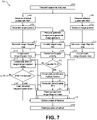
- Figure 7 illustrates a flow chart of embodiment method 700 of estimating the angle of arrival, according to an embodiment of the present invention.
- Method 700 may operate in a similar manner as method 600.
- Method 700 also compensate for Doppler components associated with vital signals of a static human. For example, during step 702, it is determined whether the target human is static or moving. If the target human is moving, method 700 proceeds in a similar manner as method 600.
- the zero-Doppler peak values of the compensated range-Doppler map are captured over a plurality of frames (step 703) in respective vectors (one per receiver) and an FFT of the vector is computed during step 704.
- an array is used to accumulate peaks over multiple frames during step 703.
- the zero-Doppler FFT vector is used to compensate the range-Doppler maps from steps 616 and 634 for micro-Doppler components, such as breathing, hand movements, etc., during step 705.
- the respective zero-Doppler vectors are based on the range-Doppler maps generated in steps 612 and 632 without compensating them in steps 616 and 634. Performing steps 703, 704, and 705 advantageously allows for compensating for low frequency Doppler velocities (e.g., lower than 1 Hz).
- each frame takes 200 ⁇ s
- 16 frames may be used during step 704, resulting in the utilization of 3.2 seconds of data.
- Different number of frames and frames with a different duration may be used.
- step 724 when the humans are moving, the phase difference is determined in a similar manner as in step 624. If the humans are static, however, the phase difference is based in the micro-Doppler compensated range-Doppler maps from step 705 (one for each receiver) instead of the compensated range-Doppler maps from steps 616 and 634.
- the angle of arrival is estimated in step 626 based on the phase difference determined in step 724.
- methods 300, 600 and 700 are performed continuously.
- target tracking and angle tracking is performed to improve the accuracy of the estimated angle of arrival.
- Figure 8 illustrates a flow chart of embodiment method 800 of estimating the angle of arrival, according to an embodiment of the present invention. The discussion that follows assumes that method 800 is implemented as part of method 600 (some steps have been omitted for clarity purposes). However, method 800 may be implemented with other methods of estimating the angle of arrival, such as methods 300, or 700, for example.
- Step 826 the angle of arrival is determined.
- Step 826 includes steps 802, 804, 806, 808, 810, 812, and 816. In some embodiments, one or more of steps 806, 808, 810, 812, and 816 are skipped.
- step 802 an initial angle of arrival is estimated using the phase mono-pulse algorithm based on the phase difference extracted in step 624 for each identified target.
- each identified target is associated with a tracked target (e.g., previously stored in memory) based on the range and Doppler velocity (estimated in step 616). For example, during step 804, the range and Doppler velocity of each identified target may be compared with historic tracks of previously identified targets (e.g., stored in memory). Each identified target, then, may be associated with a track in which the last reported range and Doppler velocity are closest to it.
- a new track is created.
- correlation between variations of identified targets are performed to determine if the identified target is a ghost human (e.g., a target suddenly appears in a location that would have required a human to move faster than humanly possible). If a target is identified as a ghost human, then no track is associated with such identified target. In some embodiments, static humans are not tracked (only tracked when the human moves).
- Tracks that are not associated with an identified target may be cancelled. Other tracking methods may be used.
- the difference in angle of arrival estimated in step 802 and the previous angle of arrival is determined during step 806. If the difference is greater that a threshold (which may be determined, for example, based on the velocity of a typical moving human), the angle of arrival is not updated. For example, in some embodiments, if the difference is greater that a threshold, the angle of arrival determined during step 802 is not used for tracking purposes, and not used for reporting the angle of arrival during step 826. For example, some embodiments may use a predicted angle of arrival (e.g., generated during step 810) instead of the estimated angle of arrival (estimated during step 802) for tracking purposes (e.g., storing in memory) and as an output of step 826.
- a threshold which may be determined, for example, based on the velocity of a typical moving human
- a sequence of Q angles of arrivals (where Q includes Q-1 previously stored angles of arrival and the currently estimated angle of arrival) is filtered using a median filter to remove outliers during step 808.
- a prediction of angle of arrival change for each identified target is generated based on an estimate of tangential velocity of each identified target (e.g., based on previously stored range and angle of arrival for the respective identified target).
- Weighting between the predicted angle of arrival and the estimated angle of arrival is performed during step 812. For example, if an identified target has an SNR higher than an SNR threshold (see step 620) and the difference in angle of arrival estimated in step 802 and the previous angle of arrival is lower than an angle threshold (see step 806), then the weights used for the predicted angle (step 810) and the measured angled (802, 808) may be 0.5 for each.
- the weights used for the predicted angle (step 810) and the measured angled (802, 808) may be 1 and 0, respective (in other words, no weight is assigned to the estimated angle of arrival and 100% weight is assigned to the predicted angle of arrival.
- the weights applied to the predicted angle of arrival and the estimated angle of arrival may be predetermined. In other embodiments, the weights applied to the predicted angle of arrival and the estimated angle of arrival are dynamically generated using, e.g., a Kalman filter or Bayesian techniques, or according to a predetermined rule(s).
- the angle of arrival is smoothened using a moving average.
- Advantages of some embodiments include the capability of accurately estimating angle of arrival of radar signals reflected in moving or static humans in low SNR regimes. Additional advantages include the improvement of SNR of reflected radar signals, thereby improving the estimate of angle of arrival. By improving the SNR, the update rate (i.e., the times in which the angle of arrival is updated - see step 620, for example) is increased. In some embodiments, by improving the estimation of the angle of arrival and by increasing the rate in which the angle of arrival is estimated, the estimation of the location of a human (including the azimuth component), and the tracking of the human in space are also improved.
- Some embodiments, such as methods 300, 600, 700 and 800, may be used in various applications Figures 9-12 show non-limiting examples of applications of methods 300, 600, 700, and 800.
- Figure 9 shows room 900 having sound system 902, according to an embodiment of the present invention.
- millimeter-wave radar 102 estimates the azimuth component of humans by estimating the angle of arrival using, e.g., method 300, 600, 700, or 800.
- Controller 904 receives (e.g., wirelessly) the azimuth components of moving (114) or static (112) humans and causes sound system 902 to direct sound to the direction of humans (e.g., using beamforming techniques known in the art).
- FIG 10 shows hotel hallway 1000, according to an embodiment of the present invention.
- millimeter-wave radar 102 (which may be installed in a ceiling of hotel hallway 1000, for example) controls one or more hotel room functions based on tracking the angle of arrival of humans moving in hotel hallway 1000. For example, in some embodiments, millimeter-wave radar 102 determines whether humans are inside each hotel room based on estimating and tracking the angle of arrival of humans as they move through hotel hallway 1000. Based on the detected human movement, millimeter-wave-radar 102 determines if humans have entered or exited each hotel room, and counts the number of humans entering or exiting each hotel room. Controller 1002 controls lights and/or HVAC of each hotel room based on the number of humans in each hotel room (e.g., controller 1002 turns off lights and HVAC in a hotel room having no humans).
- FIG 11 shows automatic gates 1102 and 1104, according to an embodiment of the present invention.
- Automatic doors 1102 and 1104 include respective millimeter-wave radars 1021 and 1022. During normal operation, millimeter-wave radars 1021 and 1022 causes automatic doors 1102 and 1104 to open or close based on humans movement. Millimeter-wave radars 102 1 and 102 2 also count the number of humans crossing in each direction by tracking the angle of arrival of human targets as they move through respective fields-of view 1106 and 1108 of millimeter-wave radars 1102 and 1104.
- millimeter-wave radars 102 1 and 102 2 are installed in automatic gates 1102 and 1104 and have the capability of detecting angle of arrival in a horizontal direction (i.e., parallel to the floor).
- Figure 12 shows another embodiment that operates in a similar manner as the embodiment of Figure 11 .
- the embodiment of Figure 12 has millimeter-wave radars 102 1 and 102 2 installed at a ceiling and having the capability of detecting angle of arrival in a vertical direction (i.e., perpendicular to the floor).
Landscapes
- Engineering & Computer Science (AREA)
- Radar, Positioning & Navigation (AREA)
- Remote Sensing (AREA)
- Physics & Mathematics (AREA)
- Computer Networks & Wireless Communication (AREA)
- General Physics & Mathematics (AREA)
- Health & Medical Sciences (AREA)
- Life Sciences & Earth Sciences (AREA)
- Biophysics (AREA)
- Molecular Biology (AREA)
- Nuclear Medicine, Radiotherapy & Molecular Imaging (AREA)
- Pathology (AREA)
- Biomedical Technology (AREA)
- Heart & Thoracic Surgery (AREA)
- Medical Informatics (AREA)
- Radiology & Medical Imaging (AREA)
- Surgery (AREA)
- Animal Behavior & Ethology (AREA)
- General Health & Medical Sciences (AREA)
- Public Health (AREA)
- Veterinary Medicine (AREA)
- Electromagnetism (AREA)
- Radar Systems Or Details Thereof (AREA)
Claims (15)
- Ein Verfahren (300, 600) zum Schätzen eines Ankunftswinkels (θ) eines an einem menschlichen Ziel reflektierten Radarsignals, das Verfahren umfassend:
Empfangen (304,314, 604, 628) des reflektierten Radarsignals (RX1, RX2) mit einer ersten und einer zweiten Antenne eines Millimeterwellenradars;Transformieren des mit der ersten und zweiten Antenne empfangenen reflektierten Radarsignals (RX1, RX2), um jeweils ein erstes und zweites Entfernungsspektrum (306,316, 606, 630) zu erzeugen;Erzeugen einer ersten Entfernungs-/Doppler-Karte (310, 612) basierend auf dem ersten Entfernungsspektrum;Erzeugen einer zweiten Entfernungs-/Doppler-Karte (320, 632) basierend auf dem zweiten Entfernungsspektrum;Bestimmen oder Schätzen (614) einer Doppler-Geschwindigkeit (v) basierend auf der ersten Entfernungs-/Doppler-Karte oder der zweiten Entfernungs-/Doppler-Karte; Makrokompensieren (616, 634) der ersten Entfernungs-/Doppler-Karte und der zweiten Entfernungs-/Doppler-Karte durch Auswählen einer Spitze in der ersten Entfernungs-/Doppler-Karte oder der zweiten Entfernungs-/Doppler-Karte basierend auf der bestimmten Doppler-Geschwindigkeit (v);Identifizieren eines Index der ersten makrokompensierten Entfernungs-/Doppler-Karte entsprechend einem identifizierten Ziel;Schätzen (324) einer Phasendifferenz (Δφ) basierend auf der ersten und zweiten makrokompensierten Entfernungs-/Doppler-Karte und dem identifizierten Index; und Schätzen (326) des Ankunftswinkels (θ) basierend auf der Phasendifferenz (Δφ). - Das Verfahren gemäß Anspruch 1, ferner umfassend ein Identifizieren (308, 610) eines Satzes von Zielentfernungs-Bins basierend auf dem ersten Entfernungsspektrum, wobei das Erzeugen der ersten Entfernungs-/Doppler-Karte (310, 612) ferner auf dem Satz von Zielentfernungs-Bins basiert.
- Das Verfahren gemäß Anspruch 2, wobei das Identifizieren (308, 610) des Satzes von Zielentfernungs-Bins auf einer Mehrdeutigkeitsfunktion (X) basiert, die einem übertragenen Radarsignal zugeordnet ist.
- Das Verfahren gemäß Anspruch 2 oder 3, wobei der Satz von Zielentfernungs-Bins eine Mehrzahl von aufeinanderfolgenden Entfernungs-Bins umfasst.
- Das Verfahren gemäß einem der Ansprüche 2 bis 4, wobei das Identifizieren des Satzes von Zielentfernungs-Bins ein Ausführen einer Spitzen-Suche auf dem ersten Entfernungsspektrum umfasst, um ein identifiziertes Zielentfernungs-Bin zu erzeugen.
- Das Verfahren gemäß Anspruch 5, wobei der Satz von Zielentfernungs-Bins zumindest drei Entfernungs-Bins umfasst, wobei die drei Entfernungs-Bins an dem identifizierten Zielentfernungs-Bin zentriert sind.
- Das Verfahren gemäß einem der vorangehenden Ansprüche, das Erzeugen (306, 606) des ersten Entfernungsspektrums umfassend:
Ausführen von N Fourier-Transformationen an N jeweiligen Impulsen des mit der ersten Antenne empfangenen reflektierten Radarsignals (RX1, RX2), um N Entfernungsspektren zu erzeugen, wobei N eine positive Ganzzahl größer als 1 ist; und
kohärentes Integrieren der N Entfernungsspektren, um das erste Entfernungsspektrum zu erzeugen. - Das Verfahren gemäß Anspruch 7, wobei N gleich 16 oder 32 ist.
- Das Verfahren gemäß Anspruch 7 oder 8, wobei N einer Gesamtanzahl von Impulsen innerhalb eines Frames entspricht.
- Das Verfahren gemäß einem der vorangehenden Ansprüche, ferner umfassend:
Erzeugen (614) eines Null-Doppler-Arrays basierend auf einer ersten oder zweiten makro kompensierten Entfernungs-/Doppler-Karte;Bestimmen einer Vitalfrequenz eines Vitalzeichens eines Menschen durch Auswählen einer Spitze des Null-Doppler-Arrays; undMikrokompensieren (705) der ersten und zweiten Entfernungs-/Doppler-Karte oder der ersten und zweiten makrokompensierten Entfernungs-/Doppler-Karte basierend auf der Vitalfrequenz. - Das Verfahren gemäß Anspruch 10, wobei das Bestimmen der Vitalfrequenz ein Ausführen (704) einer Fourier-Transformation in langsamer Zeit basierend auf der ersten Entfernungs-/Doppler-Karte umfasst.
- Das Verfahren gemäß Anspruch 10 oder 11, wobei das Vitalzeichen der Atmung eines Menschen entspricht, und wobei die Vitalfrequenz einer Atemfrequenz eines Menschen entspricht.
- Das Verfahren gemäß einem der Ansprüche 10 bis 12, wobei das Bestimmen der Vitalfrequenz ein Akkumulieren (703) von Null-Doppler-Spitzenwerten der ersten makrokompensierten Entfernungs-/Doppler-Karte über eine Mehrzahl von Frames umfasst.
- Das Verfahren gemäß einem der Ansprüche 10 bis 13, wobei die Vitalfrequenz eine Frequenz von weniger als 1 Hz aufweist.
- Ein Millimeterwellen-Radar (100), umfassend:
eine erste und eine zweite Empfangsantenne, die ausgebildet sind, ein reflektiertes Radarsignal (RX1, RX2) zu empfangen; und
eine Steuerung (904), die ausgebildet ist zum:
Transformieren des mit der ersten und zweiten Empfangsantenne empfangenen reflektierten Radarsignals (RX1, RX2), um jeweils ein erstes und zweites Entfernungsspektrum zu erzeugen;Erzeugen einer ersten Entfernungs-/Doppler-Karte (310, 612) basierend auf dem ersten Entfernungsspektrum;Erzeugen einer zweiten Entfernungs-/Doppler-Karte basierend auf dem zweiten Entfernungsspektrum;Bestimmen oder Schätzen einer Doppler-Geschwindigkeit (v) basierend auf der ersten Entfernungs-/Doppler-Karte oder der zweiten Entfernungs-/Doppler-Karte;Kompensieren der ersten Entfernungs-/Doppler-Karte und der zweiten Entfernungs-/Doppler-Karte durch Auswählen einer Spitze in der ersten Entfernungs-/Doppler-Karte oder der zweiten Entfernungs-/Doppler-Karte basierend auf der bestimmten Doppler-Geschwindigkeit (v); Identifizieren eines Index der ersten makrokompensierten Entfernungs-/Doppler-Karte entsprechend einem identifizierten Ziel;Schätzen einer Phasendifferenz (Δφ) basierend auf der ersten und zweiten makrokompensierten Entfernungs-/Doppler-Karte und dem identifizierten Index; undSchätzen eines Ankunftswinkels (θ) des reflektierten Signals basierend auf der Phasendifferenz (Δφ).
Applications Claiming Priority (1)
| Application Number | Priority Date | Filing Date | Title |
|---|---|---|---|
| US16/162,144 US11125869B2 (en) | 2018-10-16 | 2018-10-16 | Estimating angle of human target using mmWave radar |
Publications (2)
| Publication Number | Publication Date |
|---|---|
| EP3640675A1 EP3640675A1 (de) | 2020-04-22 |
| EP3640675B1 true EP3640675B1 (de) | 2022-07-20 |
Family
ID=68281022
Family Applications (1)
| Application Number | Title | Priority Date | Filing Date |
|---|---|---|---|
| EP19203217.5A Active EP3640675B1 (de) | 2018-10-16 | 2019-10-15 | Schätzung des winkels eines menschlichen zieles unter verwendung von millimeterwellenradar |
Country Status (3)
| Country | Link |
|---|---|
| US (1) | US11125869B2 (de) |
| EP (1) | EP3640675B1 (de) |
| CN (1) | CN111060903B (de) |
Families Citing this family (35)
| Publication number | Priority date | Publication date | Assignee | Title |
|---|---|---|---|---|
| KR102628655B1 (ko) * | 2018-06-29 | 2024-01-24 | 삼성전자주식회사 | 레이더 구동 장치 및 방법 |
| US11340329B2 (en) * | 2018-12-07 | 2022-05-24 | Apple Inc. | Electronic devices with broadband ranging capabilities |
| US11782148B2 (en) * | 2019-03-25 | 2023-10-10 | Texas Instruments Incorporated | Radar system |
| US11221397B2 (en) * | 2019-04-05 | 2022-01-11 | Texas Instruments Incorporated | Two-dimensional FFT computation |
| US11187782B2 (en) * | 2019-04-10 | 2021-11-30 | GM Global Technology Operations LLC | Radar system with enhanced angular resolution and method for enhancing angular resolution in a radar system |
| US11835649B2 (en) * | 2019-06-28 | 2023-12-05 | Smart Radar System, Inc. | Method and apparatus for radar signal processing using convolutional neural network |
| US11821977B2 (en) * | 2019-07-10 | 2023-11-21 | Samsung Electronics Co., Ltd. | Target detection and tracking for feature extraction |
| US11378674B2 (en) * | 2019-07-12 | 2022-07-05 | GM Global Technology Operations LLC | Object position and movement estimation using radar |
| US20210181303A1 (en) * | 2019-12-16 | 2021-06-17 | Semiconductor Components Industries, Llc | Calibrating array antennas based on signal energy distribution as a function of angle |
| KR20210101957A (ko) * | 2020-02-11 | 2021-08-19 | 삼성전자주식회사 | 레이더 시스템에서의 객체 속도 검출 방법 및 장치 |
| US11567185B2 (en) * | 2020-05-05 | 2023-01-31 | Infineon Technologies Ag | Radar-based target tracking using motion detection |
| WO2021258358A1 (zh) * | 2020-06-24 | 2021-12-30 | 华为技术有限公司 | 目标检测方法、装置、雷达以及车辆 |
| CN111983595B (zh) * | 2020-07-14 | 2023-11-10 | 北京航空航天大学杭州创新研究院 | 一种室内定位的方法及装置 |
| US11899095B2 (en) * | 2020-09-17 | 2024-02-13 | Texas Instruments Incorporated | Doppler processing in frequency-modulated continuous wave radar systems using dither |
| US11846700B2 (en) * | 2020-10-01 | 2023-12-19 | Texas Instruments Incorporated | On-field phase calibration |
| CN112419736A (zh) * | 2020-10-30 | 2021-02-26 | 航天信息股份有限公司 | 一种基于电子标识设备的运动车辆的实时定位方法及系统 |
| CN114325623B (zh) * | 2020-11-05 | 2024-05-28 | 北京航空航天大学 | 一种基于毫米波雷达的人体肢体运动信息测量方法 |
| JP2022076392A (ja) * | 2020-11-09 | 2022-05-19 | 株式会社アイシン | 生体検知装置 |
| US20220192493A1 (en) * | 2020-12-18 | 2022-06-23 | Movano Inc. | Method for monitoring a health parameter of a person that involves producing a pulse wave signal from radio frequency scanning |
| EP4024077A1 (de) * | 2021-01-04 | 2022-07-06 | Aptiv Technologies Limited | Verfahren und system zur komprimierung von radardaten |
| CN112859187B (zh) * | 2021-01-06 | 2022-11-08 | 路晟(上海)科技有限公司 | 被探测物的姿态识别方法和装置、设备及系统 |
| CN112731332A (zh) * | 2021-01-13 | 2021-04-30 | 路晟悠拜(重庆)科技有限公司 | 基于毫米波的静态目标存在识别方法及系统 |
| TWI767601B (zh) * | 2021-03-10 | 2022-06-11 | 廣達電腦股份有限公司 | 用於室內定位、成像、偵測、姿勢判別、形狀判別的電子裝置及方法 |
| CN113156430B (zh) * | 2021-04-29 | 2023-07-28 | 中国人民解放军空军工程大学 | 一种基于涡旋电磁波雷达的人体目标步态精细识别方法 |
| EP4099047B1 (de) * | 2021-06-01 | 2024-01-10 | Infineon Technologies AG | Vorverarbeitung von radarmessdaten zur objektdetektion |
| IL309199A (en) * | 2021-06-29 | 2024-02-01 | Neteera Tech Ltd | Radar-based range determination and verification |
| CN113835074B (zh) * | 2021-08-04 | 2024-01-16 | 南京常格科技发展有限公司 | 一种基于毫米波雷达的人流量动态监测方法 |
| CN113917423B (zh) * | 2021-09-28 | 2024-05-28 | 纵目科技(上海)股份有限公司 | 多普勒模糊度的计算方法、测量目标速度的方法及装置 |
| CN113866766B (zh) * | 2021-09-29 | 2024-03-22 | 电子科技大学 | 一种基于近场三维成像的雷达散射截面积精确外推方法 |
| JP2023113004A (ja) * | 2022-02-02 | 2023-08-15 | オプテックス株式会社 | 戸開閉制御装置 |
| CN114814815A (zh) * | 2022-03-16 | 2022-07-29 | 华域汽车系统股份有限公司 | 一种基于插值和单点dft滤波的解决信号处理跨越损失的方法 |
| CN114859298B (zh) * | 2022-04-26 | 2024-05-24 | 中国人民解放军空军工程大学 | 前视条件下进动锥体目标微多普勒参数提取方法 |
| CN118042602A (zh) * | 2022-11-11 | 2024-05-14 | 中兴通讯股份有限公司 | 一种均衡无线感知方法、通信节点及存储介质 |
| CN116327160B (zh) * | 2023-01-09 | 2023-11-28 | 北京航空航天大学 | 毫米波雷达生命特征检测中目标随机身体运动的误差校正方法 |
| CN115877346B (zh) * | 2023-03-04 | 2023-05-12 | 安徽隼波科技有限公司 | 一种基于二维相控阵雷达的无人机载脱靶量矢量检测方法 |
Family Cites Families (169)
| Publication number | Priority date | Publication date | Assignee | Title |
|---|---|---|---|---|
| US4241347A (en) | 1978-06-28 | 1980-12-23 | International Telephone And Telegraph Corporation | PRC/FM CW Radar system |
| JPS56100372A (en) * | 1979-12-28 | 1981-08-12 | Ibm | Movinggtarget detector |
| US4549184A (en) * | 1981-06-09 | 1985-10-22 | Grumman Aerospace Corporation | Moving target ordnance control |
| GB2247799A (en) | 1990-09-04 | 1992-03-11 | Gec Ferranti Defence Syst | Radar based navigation aid |
| US6147572A (en) | 1998-07-15 | 2000-11-14 | Lucent Technologies, Inc. | Filter including a microstrip antenna and a frequency selective surface |
| JP3393204B2 (ja) | 1999-10-06 | 2003-04-07 | 株式会社ホンダエレシス | マルチビームレーダ装置 |
| JP4115638B2 (ja) * | 1999-10-19 | 2008-07-09 | 本田技研工業株式会社 | 物体認識装置 |
| WO2001094975A1 (en) | 2000-06-06 | 2001-12-13 | Altratek Inc. | System and method for detection and tracking of targets |
| DE10037099A1 (de) | 2000-07-28 | 2002-02-07 | Wienand Hans Theo | Personenzählvorrichtung |
| JP3680029B2 (ja) | 2001-08-08 | 2005-08-10 | 三菱重工業株式会社 | 金属薄膜の気相成長方法およびその気相成長装置 |
| US7176506B2 (en) | 2001-08-28 | 2007-02-13 | Tessera, Inc. | High frequency chip packages with connecting elements |
| US6538599B1 (en) * | 2001-11-16 | 2003-03-25 | Raytheon Company | Noncoherent gain enhancement technique for non-stationary targets |
| US7948769B2 (en) | 2007-09-27 | 2011-05-24 | Hemisphere Gps Llc | Tightly-coupled PCB GNSS circuit and manufacturing method |
| KR100477647B1 (ko) | 2002-06-01 | 2005-03-23 | 삼성전자주식회사 | 영상의 움직임 보정 장치 및 방법 |
| US6963259B2 (en) | 2002-06-27 | 2005-11-08 | Harris Corporation | High efficiency resonant line |
| JP3833606B2 (ja) | 2002-12-19 | 2006-10-18 | 三菱電機株式会社 | 車載レーダ装置 |
| WO2005066649A2 (en) | 2003-12-29 | 2005-07-21 | Raytheon Canada Limited | Radar receiver motion compensation system and method |
| US7119745B2 (en) | 2004-06-30 | 2006-10-10 | International Business Machines Corporation | Apparatus and method for constructing and packaging printed antenna devices |
| EP1802996A2 (de) | 2004-07-12 | 2007-07-04 | Signal-Labs, Inc. | System und verfahren zur detektion und verfolgung von zielen |
| US7057564B2 (en) | 2004-08-31 | 2006-06-06 | Freescale Semiconductor, Inc. | Multilayer cavity slot antenna |
| US7615856B2 (en) | 2004-09-01 | 2009-11-10 | Sanyo Electric Co., Ltd. | Integrated antenna type circuit apparatus |
| US7692684B2 (en) | 2004-09-27 | 2010-04-06 | Point Grey Research Inc. | People counting systems and methods |
| JP2006234513A (ja) | 2005-02-23 | 2006-09-07 | Toyota Central Res & Dev Lab Inc | 障害物検出装置 |
| US8066642B1 (en) | 2005-05-03 | 2011-11-29 | Sonosite, Inc. | Systems and methods for ultrasound beam forming data control |
| US7596241B2 (en) | 2005-06-30 | 2009-09-29 | General Electric Company | System and method for automatic person counting and detection of specific events |
| US8228382B2 (en) | 2005-11-05 | 2012-07-24 | Ram Pattikonda | System and method for counting people |
| EP1791277A1 (de) | 2005-11-28 | 2007-05-30 | Siemens Aktiengesellschaft | Verfahren und Anordnung zur Kalibrierung von Sendepfaden eines Antennensystems |
| US20070210959A1 (en) | 2006-03-07 | 2007-09-13 | Massachusetts Institute Of Technology | Multi-beam tile array module for phased array systems |
| US7652617B2 (en) * | 2006-06-01 | 2010-01-26 | University Of Florida Research Foundation, Inc. | Radar microsensor for detection, tracking, and classification |
| US7873326B2 (en) | 2006-07-11 | 2011-01-18 | Mojix, Inc. | RFID beam forming system |
| DE102006032539A1 (de) | 2006-07-13 | 2008-01-17 | Robert Bosch Gmbh | FMCW-Radarsensor |
| CN101017202B (zh) * | 2006-12-18 | 2010-05-12 | 电子科技大学 | 一种雷达高度表及采用该表对飞行器位置的测量方法 |
| US7889147B2 (en) | 2007-02-23 | 2011-02-15 | Northrop Grumman Systems Corporation | Modular active phased array |
| US7525474B2 (en) | 2007-03-30 | 2009-04-28 | Honeywell International Inc. | Integrated distance measuring equipment and transponder system and method |
| US7675465B2 (en) | 2007-05-22 | 2010-03-09 | Sibeam, Inc. | Surface mountable integrated circuit packaging scheme |
| US8237259B2 (en) | 2007-06-13 | 2012-08-07 | Infineon Technologies Ag | Embedded chip package |
| JP4415040B2 (ja) | 2007-09-18 | 2010-02-17 | 三菱電機株式会社 | レーダ装置 |
| US7880677B2 (en) | 2007-12-12 | 2011-02-01 | Broadcom Corporation | Method and system for a phased array antenna embedded in an integrated circuit package |
| US8134425B2 (en) | 2007-12-13 | 2012-03-13 | Broadcom Corporation | Method and system for filters embedded in an integrated circuit package |
| JP4861303B2 (ja) | 2007-12-27 | 2012-01-25 | 株式会社日立製作所 | レーダセンサ |
| CN102105810B (zh) | 2008-07-24 | 2013-10-23 | 皇家飞利浦电子股份有限公司 | 三维(3-d)画面捕获 |
| CN101344589A (zh) * | 2008-08-29 | 2009-01-14 | 北京航空航天大学 | 基于gnss反射信号的空间飞行器探测装置 |
| DE102008054570A1 (de) | 2008-12-12 | 2010-06-17 | Robert Bosch Gmbh | FMCW-Radarsensor für Kraftfahrzeuge |
| EP2396887A4 (de) | 2009-02-13 | 2012-08-29 | Freescale Semiconductor Inc | Integrierte schaltung mit frequenzerzeugungsschaltkreisen zur steuerung einer frequenzquelle |
| US20100207805A1 (en) | 2009-02-19 | 2010-08-19 | Agd Systems Limited | Obtaining an indication of a number of moving objects passing speed detection apparatus |
| WO2010115418A2 (de) | 2009-04-06 | 2010-10-14 | Conti Temic Microelectronic Gmbh | Radarsystem mit anordnungen und verfahren zur entkopplung von sende- und empfangssignalen sowie unterdrückung von störeinstrahlungen |
| CN201438747U (zh) | 2009-05-18 | 2010-04-14 | 幻音科技(深圳)有限公司 | 耳塞式耳机 |
| CN101585361A (zh) | 2009-05-25 | 2009-11-25 | 郭文艺 | 汽车防碰撞防车道偏离控制装置 |
| WO2010137390A1 (ja) * | 2009-05-25 | 2010-12-02 | 株式会社 東芝 | レーダ装置 |
| US8861328B2 (en) | 2009-06-17 | 2014-10-14 | Optis Cellular Technology, Llc | Method for antenna calibration in a wideband communication system |
| EP3470963B1 (de) | 2009-07-07 | 2021-03-10 | Elliptic Laboratories AS | Steuerung anhand von bewegungen |
| US9229102B1 (en) * | 2009-12-18 | 2016-01-05 | L-3 Communications Security And Detection Systems, Inc. | Detection of movable objects |
| DE102009055262A1 (de) | 2009-12-23 | 2011-06-30 | Endress + Hauser GmbH + Co. KG, 79689 | Verfahren zur Ermittlung und Überwachung des Füllstands eines Mediums in einem Behälter nach einem Laufzeitmessverfahren |
| CN101799542B (zh) * | 2010-01-08 | 2012-06-20 | 西安电子科技大学 | 基于Adcock天线的外辐射源相干定位雷达测向方法 |
| AU2011223452A1 (en) | 2010-03-05 | 2012-09-06 | University Of Windsor | Radar system and method of manufacturing same |
| US8305261B2 (en) * | 2010-04-02 | 2012-11-06 | Raytheon Company | Adaptive mainlobe clutter method for range-Doppler maps |
| US8725085B2 (en) | 2010-06-03 | 2014-05-13 | Broadcom Corporation | RF front-end module |
| DE102010045980A1 (de) | 2010-09-18 | 2011-05-12 | Daimler Ag | Radarverfahren und Radarsystem |
| US9569003B2 (en) | 2010-09-30 | 2017-02-14 | Broadcom Corporation | Portable computing device including a three-dimensional touch screen |
| US9250319B2 (en) * | 2010-10-21 | 2016-02-02 | Reutech Radar Systems (Proprietary) Limited | Floodlight radar system for detecting and locating moving targets in three dimensions |
| JP5549560B2 (ja) | 2010-11-26 | 2014-07-16 | 富士通株式会社 | Fm−cwレーダ装置、ペアリング方法 |
| JP2012168157A (ja) | 2011-02-11 | 2012-09-06 | National Univ Corp Shizuoka Univ | 車載用のマルチビーム方式レーダ装置、マルチビーム方式レーダ方法およびマルチビーム方式レーダプログラム |
| US8988299B2 (en) | 2011-02-17 | 2015-03-24 | International Business Machines Corporation | Integrated antenna for RFIC package applications |
| JP5930590B2 (ja) * | 2011-03-04 | 2016-06-08 | 富士通テン株式会社 | レーダ装置 |
| US20120280900A1 (en) | 2011-05-06 | 2012-11-08 | Nokia Corporation | Gesture recognition using plural sensors |
| DE102011100907A1 (de) | 2011-05-09 | 2012-01-12 | Daimler Ag | Vorrichtung und Verfahren zur Ermittlung eines Fahrbahnzustands |
| DE102011075725A1 (de) | 2011-05-12 | 2012-11-15 | Robert Bosch Gmbh | Verfahren zum Erkennen von Gesten |
| US8860532B2 (en) | 2011-05-20 | 2014-10-14 | University Of Central Florida Research Foundation, Inc. | Integrated cavity filter/antenna system |
| US9183686B2 (en) | 2011-07-12 | 2015-11-10 | Tyco Fire & Security Gmbh | Method and system for people counting using passive infrared detectors |
| TW201325344A (zh) | 2011-10-20 | 2013-06-16 | Waveconnex Inc | 低輪廓的無線連接器 |
| WO2013082806A1 (en) | 2011-12-09 | 2013-06-13 | Nokia Corporation | Method and apparatus for identifying a gesture based upon fusion of multiple sensor signals |
| US9202105B1 (en) | 2012-01-13 | 2015-12-01 | Amazon Technologies, Inc. | Image analysis for user authentication |
| US9581681B2 (en) * | 2012-06-07 | 2017-02-28 | Hrl Laboratories, Llc | Method and apparatus for processing coded aperture radar (CAR) signals |
| CN102788969B (zh) | 2012-07-04 | 2015-01-28 | 中国人民解放军海军航空工程学院 | 基于短时分数阶傅里叶变换的海面微动目标检测和特征提取方法 |
| US9678573B2 (en) | 2012-07-30 | 2017-06-13 | Microsoft Technology Licensing, Llc | Interaction with devices based on user state |
| US20140070994A1 (en) | 2012-09-13 | 2014-03-13 | Toyota Motor Engineering & Manufacturing North America, Inc. | 3d short range detection with phased array radar |
| US9196951B2 (en) | 2012-11-26 | 2015-11-24 | International Business Machines Corporation | Millimeter-wave radio frequency integrated circuit packages with integrated antennas |
| CN102967854B (zh) | 2012-12-07 | 2014-08-13 | 中国人民解放军海军航空工程学院 | Frft域海杂波中目标的多重分形检测方法 |
| WO2014104189A1 (ja) | 2012-12-26 | 2014-07-03 | 日立化成株式会社 | エキスパンド方法、半導体装置の製造方法、及び半導体装置 |
| US8836596B2 (en) | 2013-01-15 | 2014-09-16 | Cubic Corporation | Filter antenna |
| US9413079B2 (en) | 2013-03-13 | 2016-08-09 | Intel Corporation | Single-package phased array module with interleaved sub-arrays |
| US9746554B2 (en) * | 2013-04-09 | 2017-08-29 | Valeo Radar Systems, Inc. | Radar imaging system and related techniques |
| KR101480348B1 (ko) | 2013-05-31 | 2015-01-09 | 삼성에스디에스 주식회사 | 사람 검출 장치 및 방법과 사람 계수 장치 및 방법 |
| US9459339B2 (en) | 2013-06-13 | 2016-10-04 | Texas Instruments Incorporated | Kalman filter for indoor positioning |
| WO2015022358A1 (en) * | 2013-08-14 | 2015-02-19 | Iee International Electronics & Engineering S.A. | Radar sensing of vehicle occupancy |
| JP6260004B2 (ja) * | 2013-08-29 | 2018-01-17 | パナソニックIpマネジメント株式会社 | レーダシステム及びターゲット検知方法 |
| JP6176007B2 (ja) * | 2013-09-06 | 2017-08-09 | 富士通株式会社 | 探知測距装置 |
| EP3045934A4 (de) * | 2013-09-12 | 2016-10-19 | Panasonic Corp | Radarvorrichtung, fahrzeug und verfahren zur erkennung der geschwindigkeit eines bewegten körpers |
| CN103529444A (zh) | 2013-09-27 | 2014-01-22 | 安徽师范大学 | 一种车载毫米波雷达动目标识别器及识别方法 |
| CN107041169B (zh) | 2013-10-07 | 2019-05-03 | Gn奈康有限公司 | 具有光学传感器的耳机设备 |
| US9753131B2 (en) | 2013-10-09 | 2017-09-05 | Massachusetts Institute Of Technology | Motion tracking via body radio reflections |
| US9759807B2 (en) | 2013-10-25 | 2017-09-12 | Texas Instruments Incorporated | Techniques for angle resolution in radar |
| US9773742B2 (en) | 2013-12-18 | 2017-09-26 | Intel Corporation | Embedded millimeter-wave phased array module |
| US20150181840A1 (en) | 2013-12-31 | 2015-07-02 | i4c Innovations Inc. | Ultra-Wideband Radar System for Animals |
| JP2015141109A (ja) | 2014-01-29 | 2015-08-03 | 富士通テン株式会社 | レーダ装置、及び、信号処理方法 |
| US9704769B2 (en) | 2014-02-27 | 2017-07-11 | STATS ChipPAC Pte. Ltd. | Semiconductor device and method of forming encapsulated wafer level chip scale package (EWLCSP) |
| CN203950036U (zh) | 2014-03-12 | 2014-11-19 | 肖令军 | 一种基于毫米波雷达测距的有人无人直升机避撞系统 |
| CN103837867B (zh) * | 2014-03-20 | 2016-03-30 | 武汉大学 | 一种利用ais信息进行高频雷达天线通道校正的方法 |
| US9921657B2 (en) | 2014-03-28 | 2018-03-20 | Intel Corporation | Radar-based gesture recognition |
| CN106659428B (zh) * | 2014-04-28 | 2020-10-16 | 麻省理工学院 | 通过无线电反射的生命体征监测 |
| CN106415454A (zh) | 2014-04-30 | 2017-02-15 | Lg伊诺特有限公司 | 触控设备、具有该触控设备的可穿戴设备及触控识别方法 |
| US9575560B2 (en) | 2014-06-03 | 2017-02-21 | Google Inc. | Radar-based gesture-recognition through a wearable device |
| US9666553B2 (en) | 2014-06-16 | 2017-05-30 | Texas Instruments Incorporated | Millimeter wave integrated circuit with ball grid array package including transmit and receive channels |
| WO2015200710A2 (en) | 2014-06-25 | 2015-12-30 | University Of Washington | Devices, systems, and methods for detecting gestures using multiple antennas and/or reflections of signals transmitted by the detecting device |
| US10627480B2 (en) | 2014-07-17 | 2020-04-21 | Texas Instruments Incorporated | Distributed radar signal processing in a radar system |
| US9921660B2 (en) | 2014-08-07 | 2018-03-20 | Google Llc | Radar-based gesture recognition |
| US9811164B2 (en) | 2014-08-07 | 2017-11-07 | Google Inc. | Radar-based gesture sensing and data transmission |
| US10094920B2 (en) | 2014-08-27 | 2018-10-09 | Texas Instruments Incorporated | Range resolution in FMCW radars |
| US9784828B2 (en) | 2014-08-27 | 2017-10-10 | Texas Insturments Incorporated | FMCW doppler processing algorithm for achieving CW performance |
| KR101628482B1 (ko) * | 2014-09-18 | 2016-06-21 | 현대자동차주식회사 | 무선신호 분석을 통한 동작 인식 시스템 및 그 방법 |
| US9600080B2 (en) | 2014-10-02 | 2017-03-21 | Google Inc. | Non-line-of-sight radar-based gesture recognition |
| US10539669B2 (en) | 2014-10-08 | 2020-01-21 | Texas Instruments Incorporated | Three dimensional (3D) tracking of objects in a radar system |
| US10634778B2 (en) | 2014-10-21 | 2020-04-28 | Texas Instruments Incorporated | Camera assisted tracking of objects in a radar system |
| US20160118353A1 (en) | 2014-10-22 | 2016-04-28 | Infineon Techologies Ag | Systems and Methods Using an RF Circuit on Isolating Material |
| KR20160058594A (ko) | 2014-11-17 | 2016-05-25 | 삼성전자주식회사 | 로봇 청소기, 단말장치 및 그 제어 방법 |
| US9733340B2 (en) | 2014-11-21 | 2017-08-15 | Texas Instruments Incorporated | Techniques for high arrival angle resolution using multiple nano-radars |
| US9829566B2 (en) | 2014-11-25 | 2017-11-28 | Texas Instruments Incorporated | Controlling radar transmission to enable interference mitigation |
| US20160306034A1 (en) | 2014-12-23 | 2016-10-20 | Infineon Technologies Ag | RF System with an RFIC and Antenna System |
| US10317512B2 (en) | 2014-12-23 | 2019-06-11 | Infineon Technologies Ag | RF system with an RFIC and antenna system |
| US9921295B2 (en) | 2014-12-30 | 2018-03-20 | Texas Instruments Incorporated | Multiple chirp generation in a radar system |
| US9696359B2 (en) | 2014-12-31 | 2017-07-04 | Texas Instruments Incorporated | Dynamic measurement of frequency synthesizer noise spurs or phase noise |
| JP6567832B2 (ja) | 2015-01-29 | 2019-08-28 | 日本電産株式会社 | レーダシステム、レーダ信号処理装置、車両走行制御装置および方法、ならびにコンピュータプログラム |
| US9939524B2 (en) * | 2015-02-04 | 2018-04-10 | Honeywell International Inc. | Systems and methods for measuring velocity with a radar altimeter |
| US10622694B2 (en) | 2015-02-12 | 2020-04-14 | Texas Instruments Incorporated | Dielectric waveguide radar signal distribution |
| US9817109B2 (en) | 2015-02-27 | 2017-11-14 | Texas Instruments Incorporated | Gesture recognition using frequency modulated continuous wave (FMCW) radar with low angle resolution |
| US10481696B2 (en) | 2015-03-03 | 2019-11-19 | Nvidia Corporation | Radar based user interface |
| CN107427206B (zh) | 2015-03-16 | 2019-11-26 | 杜邦德泽责任有限公司 | 用于气管插管的装置 |
| US10067221B2 (en) | 2015-04-06 | 2018-09-04 | Texas Instruments Incorporated | Interference detection in a frequency modulated continuous wave (FMCW) radar system |
| US9835714B2 (en) | 2015-04-09 | 2017-12-05 | Texas Instruments Incorporated | Circuit and method for impedance detection in millimeter wave systems |
| CN111880650A (zh) | 2015-04-30 | 2020-11-03 | 谷歌有限责任公司 | 基于宽场雷达的手势识别 |
| KR102002112B1 (ko) | 2015-04-30 | 2019-07-19 | 구글 엘엘씨 | 제스처 추적 및 인식을 위한 rf―기반 마이크로―모션 추적 |
| US9853365B2 (en) | 2015-05-05 | 2017-12-26 | Texas Instruments Incorporated | Dynamic programming of chirps in a frequency modulated continuous wave (FMCW) radar system |
| US10613208B2 (en) | 2015-05-15 | 2020-04-07 | Texas Instruments Incorporated | Low complexity super-resolution technique for object detection in frequency modulation continuous wave radar |
| EP3098623A1 (de) * | 2015-05-25 | 2016-11-30 | Autoliv Development AB | Fahrzeugradarsystem |
| US20160349845A1 (en) | 2015-05-28 | 2016-12-01 | Google Inc. | Gesture Detection Haptics and Virtual Tools |
| JP6531903B2 (ja) * | 2015-06-01 | 2019-06-19 | パナソニックIpマネジメント株式会社 | 物体検出装置 |
| US9870620B2 (en) * | 2015-06-18 | 2018-01-16 | The Johns Hopkins University | Non-linear associator and motion discriminator |
| US9806040B2 (en) | 2015-07-29 | 2017-10-31 | STATS ChipPAC Pte. Ltd. | Antenna in embedded wafer-level ball-grid array package |
| US10048354B2 (en) | 2015-08-13 | 2018-08-14 | Texas Instruments Incorporated | Chirp frequency non-linearity mitigation in radar systems |
| US20170054449A1 (en) | 2015-08-19 | 2017-02-23 | Texas Instruments Incorporated | Method and System for Compression of Radar Signals |
| US10555256B2 (en) | 2015-09-08 | 2020-02-04 | Texas Instruments Incorporated | Re-sampling with reduced power consumption and complexity |
| US10078131B2 (en) | 2015-09-15 | 2018-09-18 | Texas Instruments Incorporated | Method and apparatus for FMCW radar processing |
| US9886095B2 (en) | 2015-09-24 | 2018-02-06 | Stmicroelectronics Sa | Device and method for recognizing hand gestures using time-of-flight sensing |
| US10061015B2 (en) | 2015-09-30 | 2018-08-28 | Texas Instruments Incorporated | Multi-chip transceiver testing in a radar system |
| US10234542B2 (en) | 2015-09-30 | 2019-03-19 | Texas Instruments Incorporated | Measurement of transceiver performance parameters in a radar system |
| US10264996B2 (en) * | 2015-10-19 | 2019-04-23 | Sayfe Kiaei | Method and apparatus for wirelessly monitoring repetitive bodily movements |
| US10718852B2 (en) | 2015-10-23 | 2020-07-21 | Texas Instruments Incorporated | RF/mm-wave peak detector with high-dynamic range calibration |
| US9759808B2 (en) | 2015-11-12 | 2017-09-12 | Texas Instruments Incorporated | Buffer sample size control for variable chirp radar |
| WO2017084700A1 (de) | 2015-11-17 | 2017-05-26 | Vega Grieshaber Kg | Antennenvorrichtung und verfahren zum senden und/oder empfangen eines signals |
| KR102427185B1 (ko) | 2015-12-09 | 2022-08-01 | 삼성전자 주식회사 | 스위치 운용 방법 및 이를 지원하는 전자 장치 |
| US10746851B2 (en) | 2015-12-18 | 2020-08-18 | Texas Instruments Incorporated | Circuits and methods for determining chirp signal linearity and phase noise of a FMCW radar |
| US10599518B2 (en) | 2015-12-31 | 2020-03-24 | Texas Instruments Incorporated | Protecting data memory in a signal processing system |
| US10530053B2 (en) | 2016-01-13 | 2020-01-07 | Infineon Technologies Ag | System and method for measuring a plurality of RF signal paths |
| US9965043B2 (en) | 2016-01-27 | 2018-05-08 | Wipro Limited | Method and system for recommending one or more gestures to users interacting with computing device |
| US9846228B2 (en) * | 2016-04-07 | 2017-12-19 | Uhnder, Inc. | Software defined automotive radar systems |
| JP2017223461A (ja) * | 2016-06-13 | 2017-12-21 | パナソニックIpマネジメント株式会社 | レーダ装置および検出方法 |
| US10514770B2 (en) | 2016-06-17 | 2019-12-24 | Texas Instruments Incorporated | Hidden Markov model-based gesture recognition with FMCW radar |
| US20180011181A1 (en) * | 2016-07-07 | 2018-01-11 | Infineon Technologies Ag | Radar systems and methods thereof |
| US20180046255A1 (en) | 2016-08-09 | 2018-02-15 | Google Inc. | Radar-based gestural interface |
| FR3055049B1 (fr) * | 2016-08-11 | 2018-07-27 | Thales | Procede de detection radar fmcw a resolution multiple et radar mettant en oeuvre un tel procede |
| CN106980362A (zh) | 2016-10-09 | 2017-07-25 | 阿里巴巴集团控股有限公司 | 基于虚拟现实场景的输入方法及装置 |
| US9935065B1 (en) | 2016-12-21 | 2018-04-03 | Infineon Technologies Ag | Radio frequency device packages and methods of formation thereof |
| US10591596B2 (en) * | 2017-05-11 | 2020-03-17 | GM Global Technology Operations LLC | Doppler resolution improvement in low-duty cycle transmission |
| US10641885B2 (en) * | 2017-07-21 | 2020-05-05 | Honeywell International Inc. | Systems and methods for measuring velocity and acceleration with a radar altimeter |
| CN108469607B (zh) * | 2018-03-16 | 2022-03-22 | 西安电子科技大学 | 基于频率扫描天线的无人机探测雷达测角方法 |
| US10690745B2 (en) * | 2018-04-18 | 2020-06-23 | Raytheon Company | Methods and systems for pulse association of agile emitters |
| US20190346548A1 (en) * | 2018-05-11 | 2019-11-14 | GM Global Technology Operations LLC | Filtering to address range walk effect in range-doppler map |
| US11119185B2 (en) * | 2018-06-07 | 2021-09-14 | GM Global Technology Operations LLC | Resolving doppler ambiguity in multi-input multi-output radar using digital multiple pulse repetition frequencies |
| US10962636B2 (en) * | 2018-08-13 | 2021-03-30 | GM Global Technology Operations LLC | Range and direction of arrival migration with doppler ambiguity estimation |
-
2018
- 2018-10-16 US US16/162,144 patent/US11125869B2/en active Active
-
2019
- 2019-10-15 EP EP19203217.5A patent/EP3640675B1/de active Active
- 2019-10-16 CN CN201910982805.3A patent/CN111060903B/zh active Active
Also Published As
| Publication number | Publication date |
|---|---|
| CN111060903B (zh) | 2024-04-12 |
| US20200116850A1 (en) | 2020-04-16 |
| EP3640675A1 (de) | 2020-04-22 |
| CN111060903A (zh) | 2020-04-24 |
| US11125869B2 (en) | 2021-09-21 |
Similar Documents
| Publication | Publication Date | Title |
|---|---|---|
| EP3640675B1 (de) | Schätzung des winkels eines menschlichen zieles unter verwendung von millimeterwellenradar | |
| CN111157981B (zh) | 多入多出调频连续波雷达系统 | |
| US11016171B2 (en) | Radar sensing with phase correction | |
| JP6726253B2 (ja) | 干渉抑制を用いるレーダー検出 | |
| US11061127B2 (en) | Vehicle radar system | |
| US9470782B2 (en) | Method and apparatus for increasing angular resolution in an automotive radar system | |
| US7961147B1 (en) | Long baseline phase interferometer ambiguity resolution using frequency differences | |
| US11209523B2 (en) | FMCW radar with interference signal rejection | |
| US11592520B2 (en) | FMCW radar with interfering signal suppression in the time domain | |
| KR20180083865A (ko) | 인터리빙된 직렬 송신 및 병렬 수신을 포함하는 레이더 시스템 | |
| CN109477892B (zh) | 用于环境检测的车辆雷达 | |
| US8384587B2 (en) | Radar for aerial target detection fitted to an aircraft notably for the avoidance of obstacles in flight | |
| CN111077514A (zh) | 具有干扰信号抑制的fmcw雷达 | |
| EP4009074B1 (de) | Mimo-radar-verfahren und -system mit co-prime-codierter (cpc) dopplermultiplex-ing (ddm) | |
| US9285469B1 (en) | Multiplatform GMTI radar with enhanced SNR, monopulse | |
| US20230066386A1 (en) | Tdm fmcw radar apparatus and signal processing method of apparatus | |
| US11960023B2 (en) | Radar device | |
| KR101052050B1 (ko) | 다수의 레이더를 가간섭적으로 결합하여 이동 표적의 감지율을 향상시키는 방법 및 그 방법이 적용된 레이더 시스템 | |
| JP3061738B2 (ja) | マルチprf法を用いた測距装置および測距方法 | |
| EP4343368A1 (de) | Radarbasierte segmentierte präsenzerkennung | |
| Radmard et al. | Target's range migration compensation in passive radar | |
| US20240134002A1 (en) | Phase imbalance detection in a frequency modulated continuous wave radar system | |
| US20230176187A1 (en) | Tdm fmcw radar apparatus and signal processing method of apparatus | |
| Weiß | Distributed sensor systems | |
| Lv et al. | Ground moving target indication and parameters estimation using a dual-frequency synthetic aperture radar |
Legal Events
| Date | Code | Title | Description |
|---|---|---|---|
| PUAI | Public reference made under article 153(3) epc to a published international application that has entered the european phase |
Free format text: ORIGINAL CODE: 0009012 |
|
| STAA | Information on the status of an ep patent application or granted ep patent |
Free format text: STATUS: THE APPLICATION HAS BEEN PUBLISHED |
|
| AK | Designated contracting states |
Kind code of ref document: A1 Designated state(s): AL AT BE BG CH CY CZ DE DK EE ES FI FR GB GR HR HU IE IS IT LI LT LU LV MC MK MT NL NO PL PT RO RS SE SI SK SM TR |
|
| AX | Request for extension of the european patent |
Extension state: BA ME |
|
| STAA | Information on the status of an ep patent application or granted ep patent |
Free format text: STATUS: REQUEST FOR EXAMINATION WAS MADE |
|
| 17P | Request for examination filed |
Effective date: 20201016 |
|
| RBV | Designated contracting states (corrected) |
Designated state(s): AL AT BE BG CH CY CZ DE DK EE ES FI FR GB GR HR HU IE IS IT LI LT LU LV MC MK MT NL NO PL PT RO RS SE SI SK SM TR |
|
| GRAP | Despatch of communication of intention to grant a patent |
Free format text: ORIGINAL CODE: EPIDOSNIGR1 |
|
| STAA | Information on the status of an ep patent application or granted ep patent |
Free format text: STATUS: GRANT OF PATENT IS INTENDED |
|
| RIC1 | Information provided on ipc code assigned before grant |
Ipc: A61B 5/113 20060101ALN20220303BHEP Ipc: A61B 5/11 20060101ALN20220303BHEP Ipc: A61B 5/00 20060101ALN20220303BHEP Ipc: G01S 7/35 20060101ALN20220303BHEP Ipc: G01S 7/288 20060101ALN20220303BHEP Ipc: A61B 5/0507 20210101ALI20220303BHEP Ipc: A61B 5/08 20060101ALI20220303BHEP Ipc: G01S 13/72 20060101ALI20220303BHEP Ipc: G01S 13/44 20060101ALI20220303BHEP Ipc: G01S 13/88 20060101ALI20220303BHEP Ipc: G01S 13/58 20060101AFI20220303BHEP |
|
| INTG | Intention to grant announced |
Effective date: 20220324 |
|
| GRAS | Grant fee paid |
Free format text: ORIGINAL CODE: EPIDOSNIGR3 |
|
| GRAA | (expected) grant |
Free format text: ORIGINAL CODE: 0009210 |
|
| STAA | Information on the status of an ep patent application or granted ep patent |
Free format text: STATUS: THE PATENT HAS BEEN GRANTED |
|
| AK | Designated contracting states |
Kind code of ref document: B1 Designated state(s): AL AT BE BG CH CY CZ DE DK EE ES FI FR GB GR HR HU IE IS IT LI LT LU LV MC MK MT NL NO PL PT RO RS SE SI SK SM TR |
|
| REG | Reference to a national code |
Ref country code: CH Ref legal event code: EP |
|
| REG | Reference to a national code |
Ref country code: DE Ref legal event code: R096 Ref document number: 602019017150 Country of ref document: DE |
|
| REG | Reference to a national code |
Ref country code: AT Ref legal event code: REF Ref document number: 1505871 Country of ref document: AT Kind code of ref document: T Effective date: 20220815 |
|
| REG | Reference to a national code |
Ref country code: IE Ref legal event code: FG4D |
|
| REG | Reference to a national code |
Ref country code: LT Ref legal event code: MG9D |
|
| REG | Reference to a national code |
Ref country code: NL Ref legal event code: MP Effective date: 20220720 |
|
| PG25 | Lapsed in a contracting state [announced via postgrant information from national office to epo] |
Ref country code: SE Free format text: LAPSE BECAUSE OF FAILURE TO SUBMIT A TRANSLATION OF THE DESCRIPTION OR TO PAY THE FEE WITHIN THE PRESCRIBED TIME-LIMIT Effective date: 20220720 Ref country code: RS Free format text: LAPSE BECAUSE OF FAILURE TO SUBMIT A TRANSLATION OF THE DESCRIPTION OR TO PAY THE FEE WITHIN THE PRESCRIBED TIME-LIMIT Effective date: 20220720 Ref country code: PT Free format text: LAPSE BECAUSE OF FAILURE TO SUBMIT A TRANSLATION OF THE DESCRIPTION OR TO PAY THE FEE WITHIN THE PRESCRIBED TIME-LIMIT Effective date: 20221121 Ref country code: NO Free format text: LAPSE BECAUSE OF FAILURE TO SUBMIT A TRANSLATION OF THE DESCRIPTION OR TO PAY THE FEE WITHIN THE PRESCRIBED TIME-LIMIT Effective date: 20221020 Ref country code: NL Free format text: LAPSE BECAUSE OF FAILURE TO SUBMIT A TRANSLATION OF THE DESCRIPTION OR TO PAY THE FEE WITHIN THE PRESCRIBED TIME-LIMIT Effective date: 20220720 Ref country code: LV Free format text: LAPSE BECAUSE OF FAILURE TO SUBMIT A TRANSLATION OF THE DESCRIPTION OR TO PAY THE FEE WITHIN THE PRESCRIBED TIME-LIMIT Effective date: 20220720 Ref country code: LT Free format text: LAPSE BECAUSE OF FAILURE TO SUBMIT A TRANSLATION OF THE DESCRIPTION OR TO PAY THE FEE WITHIN THE PRESCRIBED TIME-LIMIT Effective date: 20220720 Ref country code: FI Free format text: LAPSE BECAUSE OF FAILURE TO SUBMIT A TRANSLATION OF THE DESCRIPTION OR TO PAY THE FEE WITHIN THE PRESCRIBED TIME-LIMIT Effective date: 20220720 Ref country code: ES Free format text: LAPSE BECAUSE OF FAILURE TO SUBMIT A TRANSLATION OF THE DESCRIPTION OR TO PAY THE FEE WITHIN THE PRESCRIBED TIME-LIMIT Effective date: 20220720 |
|
| REG | Reference to a national code |
Ref country code: AT Ref legal event code: MK05 Ref document number: 1505871 Country of ref document: AT Kind code of ref document: T Effective date: 20220720 |
|
| PG25 | Lapsed in a contracting state [announced via postgrant information from national office to epo] |
Ref country code: PL Free format text: LAPSE BECAUSE OF FAILURE TO SUBMIT A TRANSLATION OF THE DESCRIPTION OR TO PAY THE FEE WITHIN THE PRESCRIBED TIME-LIMIT Effective date: 20220720 Ref country code: IS Free format text: LAPSE BECAUSE OF FAILURE TO SUBMIT A TRANSLATION OF THE DESCRIPTION OR TO PAY THE FEE WITHIN THE PRESCRIBED TIME-LIMIT Effective date: 20221120 Ref country code: HR Free format text: LAPSE BECAUSE OF FAILURE TO SUBMIT A TRANSLATION OF THE DESCRIPTION OR TO PAY THE FEE WITHIN THE PRESCRIBED TIME-LIMIT Effective date: 20220720 Ref country code: GR Free format text: LAPSE BECAUSE OF FAILURE TO SUBMIT A TRANSLATION OF THE DESCRIPTION OR TO PAY THE FEE WITHIN THE PRESCRIBED TIME-LIMIT Effective date: 20221021 |
|
| REG | Reference to a national code |
Ref country code: DE Ref legal event code: R097 Ref document number: 602019017150 Country of ref document: DE |
|
| PG25 | Lapsed in a contracting state [announced via postgrant information from national office to epo] |
Ref country code: SM Free format text: LAPSE BECAUSE OF FAILURE TO SUBMIT A TRANSLATION OF THE DESCRIPTION OR TO PAY THE FEE WITHIN THE PRESCRIBED TIME-LIMIT Effective date: 20220720 Ref country code: RO Free format text: LAPSE BECAUSE OF FAILURE TO SUBMIT A TRANSLATION OF THE DESCRIPTION OR TO PAY THE FEE WITHIN THE PRESCRIBED TIME-LIMIT Effective date: 20220720 Ref country code: DK Free format text: LAPSE BECAUSE OF FAILURE TO SUBMIT A TRANSLATION OF THE DESCRIPTION OR TO PAY THE FEE WITHIN THE PRESCRIBED TIME-LIMIT Effective date: 20220720 Ref country code: CZ Free format text: LAPSE BECAUSE OF FAILURE TO SUBMIT A TRANSLATION OF THE DESCRIPTION OR TO PAY THE FEE WITHIN THE PRESCRIBED TIME-LIMIT Effective date: 20220720 Ref country code: AT Free format text: LAPSE BECAUSE OF FAILURE TO SUBMIT A TRANSLATION OF THE DESCRIPTION OR TO PAY THE FEE WITHIN THE PRESCRIBED TIME-LIMIT Effective date: 20220720 |
|
| PLBE | No opposition filed within time limit |
Free format text: ORIGINAL CODE: 0009261 |
|
| STAA | Information on the status of an ep patent application or granted ep patent |
Free format text: STATUS: NO OPPOSITION FILED WITHIN TIME LIMIT |
|
| PG25 | Lapsed in a contracting state [announced via postgrant information from national office to epo] |
Ref country code: SK Free format text: LAPSE BECAUSE OF FAILURE TO SUBMIT A TRANSLATION OF THE DESCRIPTION OR TO PAY THE FEE WITHIN THE PRESCRIBED TIME-LIMIT Effective date: 20220720 Ref country code: MC Free format text: LAPSE BECAUSE OF FAILURE TO SUBMIT A TRANSLATION OF THE DESCRIPTION OR TO PAY THE FEE WITHIN THE PRESCRIBED TIME-LIMIT Effective date: 20220720 Ref country code: EE Free format text: LAPSE BECAUSE OF FAILURE TO SUBMIT A TRANSLATION OF THE DESCRIPTION OR TO PAY THE FEE WITHIN THE PRESCRIBED TIME-LIMIT Effective date: 20220720 |
|
| REG | Reference to a national code |
Ref country code: CH Ref legal event code: PL |
|
| REG | Reference to a national code |
Ref country code: BE Ref legal event code: MM Effective date: 20221031 |
|
| 26N | No opposition filed |
Effective date: 20230421 |
|
| PG25 | Lapsed in a contracting state [announced via postgrant information from national office to epo] |
Ref country code: LU Free format text: LAPSE BECAUSE OF NON-PAYMENT OF DUE FEES Effective date: 20221015 Ref country code: AL Free format text: LAPSE BECAUSE OF FAILURE TO SUBMIT A TRANSLATION OF THE DESCRIPTION OR TO PAY THE FEE WITHIN THE PRESCRIBED TIME-LIMIT Effective date: 20220720 |
|
| P01 | Opt-out of the competence of the unified patent court (upc) registered |
Effective date: 20230528 |
|
| PG25 | Lapsed in a contracting state [announced via postgrant information from national office to epo] |
Ref country code: LI Free format text: LAPSE BECAUSE OF NON-PAYMENT OF DUE FEES Effective date: 20221031 Ref country code: CH Free format text: LAPSE BECAUSE OF NON-PAYMENT OF DUE FEES Effective date: 20221031 |
|
| PG25 | Lapsed in a contracting state [announced via postgrant information from national office to epo] |
Ref country code: SI Free format text: LAPSE BECAUSE OF FAILURE TO SUBMIT A TRANSLATION OF THE DESCRIPTION OR TO PAY THE FEE WITHIN THE PRESCRIBED TIME-LIMIT Effective date: 20220720 |
|
| PG25 | Lapsed in a contracting state [announced via postgrant information from national office to epo] |
Ref country code: BE Free format text: LAPSE BECAUSE OF NON-PAYMENT OF DUE FEES Effective date: 20221031 |
|
| PG25 | Lapsed in a contracting state [announced via postgrant information from national office to epo] |
Ref country code: IE Free format text: LAPSE BECAUSE OF NON-PAYMENT OF DUE FEES Effective date: 20221015 |
|
| PGFP | Annual fee paid to national office [announced via postgrant information from national office to epo] |
Ref country code: GB Payment date: 20231020 Year of fee payment: 5 |
|
| PGFP | Annual fee paid to national office [announced via postgrant information from national office to epo] |
Ref country code: FR Payment date: 20231026 Year of fee payment: 5 Ref country code: DE Payment date: 20231218 Year of fee payment: 5 |
|
| PG25 | Lapsed in a contracting state [announced via postgrant information from national office to epo] |
Ref country code: HU Free format text: LAPSE BECAUSE OF FAILURE TO SUBMIT A TRANSLATION OF THE DESCRIPTION OR TO PAY THE FEE WITHIN THE PRESCRIBED TIME-LIMIT; INVALID AB INITIO Effective date: 20191015 |
|
| PG25 | Lapsed in a contracting state [announced via postgrant information from national office to epo] |
Ref country code: CY Free format text: LAPSE BECAUSE OF FAILURE TO SUBMIT A TRANSLATION OF THE DESCRIPTION OR TO PAY THE FEE WITHIN THE PRESCRIBED TIME-LIMIT Effective date: 20220720 |