US11187782B2 - Radar system with enhanced angular resolution and method for enhancing angular resolution in a radar system - Google Patents
Radar system with enhanced angular resolution and method for enhancing angular resolution in a radar system Download PDFInfo
- Publication number
- US11187782B2 US11187782B2 US16/380,498 US201916380498A US11187782B2 US 11187782 B2 US11187782 B2 US 11187782B2 US 201916380498 A US201916380498 A US 201916380498A US 11187782 B2 US11187782 B2 US 11187782B2
- Authority
- US
- United States
- Prior art keywords
- vector
- velocity
- beamforming
- radar system
- equation
- Prior art date
- Legal status (The legal status is an assumption and is not a legal conclusion. Google has not performed a legal analysis and makes no representation as to the accuracy of the status listed.)
- Active, expires
Links
Images


Classifications
-
- G—PHYSICS
- G01—MEASURING; TESTING
- G01S—RADIO DIRECTION-FINDING; RADIO NAVIGATION; DETERMINING DISTANCE OR VELOCITY BY USE OF RADIO WAVES; LOCATING OR PRESENCE-DETECTING BY USE OF THE REFLECTION OR RERADIATION OF RADIO WAVES; ANALOGOUS ARRANGEMENTS USING OTHER WAVES
- G01S13/00—Systems using the reflection or reradiation of radio waves, e.g. radar systems; Analogous systems using reflection or reradiation of waves whose nature or wavelength is irrelevant or unspecified
- G01S13/88—Radar or analogous systems specially adapted for specific applications
- G01S13/93—Radar or analogous systems specially adapted for specific applications for anti-collision purposes
- G01S13/931—Radar or analogous systems specially adapted for specific applications for anti-collision purposes of land vehicles
-
- G—PHYSICS
- G01—MEASURING; TESTING
- G01S—RADIO DIRECTION-FINDING; RADIO NAVIGATION; DETERMINING DISTANCE OR VELOCITY BY USE OF RADIO WAVES; LOCATING OR PRESENCE-DETECTING BY USE OF THE REFLECTION OR RERADIATION OF RADIO WAVES; ANALOGOUS ARRANGEMENTS USING OTHER WAVES
- G01S7/00—Details of systems according to groups G01S13/00, G01S15/00, G01S17/00
- G01S7/02—Details of systems according to groups G01S13/00, G01S15/00, G01S17/00 of systems according to group G01S13/00
- G01S7/28—Details of pulse systems
- G01S7/285—Receivers
-
- G—PHYSICS
- G01—MEASURING; TESTING
- G01S—RADIO DIRECTION-FINDING; RADIO NAVIGATION; DETERMINING DISTANCE OR VELOCITY BY USE OF RADIO WAVES; LOCATING OR PRESENCE-DETECTING BY USE OF THE REFLECTION OR RERADIATION OF RADIO WAVES; ANALOGOUS ARRANGEMENTS USING OTHER WAVES
- G01S13/00—Systems using the reflection or reradiation of radio waves, e.g. radar systems; Analogous systems using reflection or reradiation of waves whose nature or wavelength is irrelevant or unspecified
- G01S13/02—Systems using reflection of radio waves, e.g. primary radar systems; Analogous systems
- G01S13/06—Systems determining position data of a target
- G01S13/08—Systems for measuring distance only
- G01S13/10—Systems for measuring distance only using transmission of interrupted, pulse modulated waves
-
- G—PHYSICS
- G01—MEASURING; TESTING
- G01S—RADIO DIRECTION-FINDING; RADIO NAVIGATION; DETERMINING DISTANCE OR VELOCITY BY USE OF RADIO WAVES; LOCATING OR PRESENCE-DETECTING BY USE OF THE REFLECTION OR RERADIATION OF RADIO WAVES; ANALOGOUS ARRANGEMENTS USING OTHER WAVES
- G01S7/00—Details of systems according to groups G01S13/00, G01S15/00, G01S17/00
- G01S7/02—Details of systems according to groups G01S13/00, G01S15/00, G01S17/00 of systems according to group G01S13/00
- G01S7/28—Details of pulse systems
- G01S7/282—Transmitters
-
- G—PHYSICS
- G01—MEASURING; TESTING
- G01S—RADIO DIRECTION-FINDING; RADIO NAVIGATION; DETERMINING DISTANCE OR VELOCITY BY USE OF RADIO WAVES; LOCATING OR PRESENCE-DETECTING BY USE OF THE REFLECTION OR RERADIATION OF RADIO WAVES; ANALOGOUS ARRANGEMENTS USING OTHER WAVES
- G01S7/00—Details of systems according to groups G01S13/00, G01S15/00, G01S17/00
- G01S7/02—Details of systems according to groups G01S13/00, G01S15/00, G01S17/00 of systems according to group G01S13/00
- G01S7/41—Details of systems according to groups G01S13/00, G01S15/00, G01S17/00 of systems according to group G01S13/00 using analysis of echo signal for target characterisation; Target signature; Target cross-section
-
- G—PHYSICS
- G01—MEASURING; TESTING
- G01S—RADIO DIRECTION-FINDING; RADIO NAVIGATION; DETERMINING DISTANCE OR VELOCITY BY USE OF RADIO WAVES; LOCATING OR PRESENCE-DETECTING BY USE OF THE REFLECTION OR RERADIATION OF RADIO WAVES; ANALOGOUS ARRANGEMENTS USING OTHER WAVES
- G01S13/00—Systems using the reflection or reradiation of radio waves, e.g. radar systems; Analogous systems using reflection or reradiation of waves whose nature or wavelength is irrelevant or unspecified
- G01S13/88—Radar or analogous systems specially adapted for specific applications
- G01S13/93—Radar or analogous systems specially adapted for specific applications for anti-collision purposes
- G01S13/931—Radar or analogous systems specially adapted for specific applications for anti-collision purposes of land vehicles
- G01S2013/9316—Radar or analogous systems specially adapted for specific applications for anti-collision purposes of land vehicles combined with communication equipment with other vehicles or with base stations
-
- G—PHYSICS
- G01—MEASURING; TESTING
- G01S—RADIO DIRECTION-FINDING; RADIO NAVIGATION; DETERMINING DISTANCE OR VELOCITY BY USE OF RADIO WAVES; LOCATING OR PRESENCE-DETECTING BY USE OF THE REFLECTION OR RERADIATION OF RADIO WAVES; ANALOGOUS ARRANGEMENTS USING OTHER WAVES
- G01S13/00—Systems using the reflection or reradiation of radio waves, e.g. radar systems; Analogous systems using reflection or reradiation of waves whose nature or wavelength is irrelevant or unspecified
- G01S13/88—Radar or analogous systems specially adapted for specific applications
- G01S13/93—Radar or analogous systems specially adapted for specific applications for anti-collision purposes
- G01S13/931—Radar or analogous systems specially adapted for specific applications for anti-collision purposes of land vehicles
- G01S2013/93185—Controlling the brakes
-
- G—PHYSICS
- G01—MEASURING; TESTING
- G01S—RADIO DIRECTION-FINDING; RADIO NAVIGATION; DETERMINING DISTANCE OR VELOCITY BY USE OF RADIO WAVES; LOCATING OR PRESENCE-DETECTING BY USE OF THE REFLECTION OR RERADIATION OF RADIO WAVES; ANALOGOUS ARRANGEMENTS USING OTHER WAVES
- G01S13/00—Systems using the reflection or reradiation of radio waves, e.g. radar systems; Analogous systems using reflection or reradiation of waves whose nature or wavelength is irrelevant or unspecified
- G01S13/88—Radar or analogous systems specially adapted for specific applications
- G01S13/93—Radar or analogous systems specially adapted for specific applications for anti-collision purposes
- G01S13/931—Radar or analogous systems specially adapted for specific applications for anti-collision purposes of land vehicles
- G01S2013/9327—Sensor installation details
- G01S2013/93271—Sensor installation details in the front of the vehicles
Definitions
- the subject disclosure relates to a system and method for improving angular resolution in a radar system.
- LIDAR Light Detection and Ranging
- a radar system with enhanced angular resolution it may be desirable to provide a radar system with enhanced angular resolution, a method for enhancing angular resolution of a radar system, and a vehicle implementing such a radar system or method in conjunction with an automated driving system.
- a radar system for use with multiple targets when there is relative motion between the radar system and the multiple targets may include an antenna structured to transmit a radar signal and receive reflected radar signals from targets and a processor operably connected to the antenna.
- the processor may be configured to control the radar system to perform receiving a first reflected signal at a first time.
- the first reflected signal may be characterized by a first vector having a first set of arrival angles.
- the processor may be further configured to control the radar system to perform receiving a second reflected signal at a second time.
- the second reflected signal may be characterized by a second vector having a second set of arrival angles.
- the second set of arrival angles may be equal to the first set of arrival angles plus an angle offset which is calculated based on a velocity hypothesis.
- the processor may be configured to control the radar system to perform translating the first vector by applying the angle offset, thereby calculating a translated first vector.
- the processor may be configured to control the radar system to perform calculating a beamforming spectrum based on the translated first vector and the second vector.
- the processor may be configured to control the radar system to perform identifying peaks in the beamforming spectrum to identify angular positions of the multiple targets.
- the processor may be configured such that the identifying peaks in the beamforming spectrum includes calculating a velocity score of the beamforming spectrum and iteratively adjusting the velocity hypothesis until an optimal velocity hypothesis is determined.
- the optimal velocity hypothesis may be a velocity hypothesis for which the velocity score of the beamforming spectrum reaches a minimum velocity score
- an optimal beamforming spectrum may be a beamforming spectrum generated using the optimal velocity hypothesis.
- the processor may be further configured to control the radar system to perform identifying peaks in the optimal beamforming spectrum to identify angular positions of the multiple targets.
- y 1 is the first vector
- M is the number of reflections
- ⁇ m is the first set of arrival angles
- a( ⁇ m ) [e ⁇ j2 ⁇ / ⁇ x 1 sin ⁇ m . . . e ⁇ j2 ⁇ / ⁇ x N sin ⁇ m ]
- T is the array response at angle ⁇ m where ⁇ is a wavelength and x i is the i-th antenna position;
- c m is a complex reflection coefficient for the signal arriving from angle ⁇ m
- v 1 is a first noise factor.
- y 2 is the second vector
- ⁇ is the angle offset
- a( ⁇ m + ⁇ ) is an array response at angle ⁇ m + ⁇
- b m is a second complex reflector coefficient
- v 2 is a second noise factor.
- the radar system may include N antenna elements, ⁇ is the wavelength; and x 1 , x 2 , . . . , x N are positions of the N antenna elements.
- the beamforming spectrum may be given by the equation
- P ⁇ ( ⁇ ) 1 a H ⁇ ( ⁇ ) ⁇ ( R + ⁇ ⁇ ⁇ I ) - 1 ⁇ a ⁇ ( ⁇ )
- P( ⁇ ) is the beamforming spectrum
- a( ⁇ ) is an array response at angle ⁇
- ⁇ is a regularization factor
- I is an identity matrix
- superscript H represents a Hermitian transpose
- y 1 is the translated first vector and y 2 is the second vector.
- ⁇ ⁇ ⁇ P ⁇ ( ⁇ ) ⁇ 2 ⁇ ⁇ ⁇ ⁇ P ⁇ ( ⁇ ) ⁇ 2 .
- the processor may be further configured to output the optimal velocity hypothesis as an estimated velocity vector corresponding to relative motion between the radar system and the multiple targets.
- the processor may be further configured to output angles corresponding to the peaks in the optimal beamforming spectrum as an estimated angular location of the multiple targets.
- the antenna and the processor may be provided in a vehicle comprising an automated driving system operably connected to the radar system.
- the automated driving system may be structured to autonomously control the vehicle.
- the processor may be configured to transmit the estimated velocity vector and the estimated angular positions of the multiple targets to the automated driving system.
- the automated driving system may be structured to control operation of the vehicle based on the estimated velocity vector and the estimated angular positions of the multiple targets.
- a vehicle may include an automated driving system structured to autonomously control the vehicle.
- the vehicle may further include a radar system operably connected to the automated driving system.
- the radar system may be structured for use with multiple targets when there is relative motion between the radar system and the multiple targets.
- the radar system may include an antenna structured to transmit a radar signal and receive reflected radar signals from targets and a processor operably connected to the antenna.
- the processor may be configured to control the radar system to perform receiving a first reflected signal at a first time.
- the first reflected signal may be characterized by a first vector having a first set of arrival angles.
- the processor may be further configured to perform receiving a second reflected signal at a second time.
- the second reflected signal may be characterized by a second vector having a second set of arrival angles.
- the second set of arrival angles may be equal to the first set of arrival angles plus an angle offset which is calculated based on a velocity hypothesis.
- the processor may be further configured to perform translating the first vector by applying the angle offset, thereby calculating a translated first vector.
- the processor may be further configured to perform calculating a beamforming spectrum based on the translated first vector and the second vector.
- the processor may be further configured to perform identifying peaks in the beamforming spectrum to identify angular positions of the multiple targets.
- the processor may be further configured to perform transmitting the velocity hypothesis to the autonomous driving system as an estimated velocity vector.
- the processor may be further configured to perform transmitting the angular positions of the multiple targets to the autonomous driving system.
- the automated driving system may be structured to control operation of the vehicle based on the estimated velocity vector and the angular positions of the multiple targets.
- the processor may be configured such that the identifying peaks in the beamforming spectrum includes calculating a velocity score of the beamforming spectrum and iteratively adjusting the velocity hypothesis until an optimal velocity hypothesis is determined.
- the optimal velocity hypothesis may be a velocity hypothesis for which the velocity score of the beamforming spectrum reaches a minimum velocity score, and an optimal beamforming spectrum being a beamforming spectrum generated using the optimal velocity hypothesis.
- the processor may be further configured to perform identifying peaks in the optimal beamforming spectrum to identify angular positions of the multiple targets.
- a beamforming method for a radar system for use with multiple targets when there is relative motion between the radar system and the multiple targets may include receiving, with the radar system, a first reflected signal at a first time.
- the first reflected signal may be characterized by a first vector having a first set of arrival angles.
- the beamforming method may further include receiving, with the radar system, a second reflected signal at a second time.
- the second reflected signal may be characterized by a second vector having a second set of arrival angles.
- the second set of arrival angles may be equal to the first set of arrival angles plus an angle offset which is calculated based on a velocity hypothesis.
- the beamforming method may further include translating the first vector by applying the angle offset, thereby calculating a translated first vector.
- the beamforming method may include calculating a beamforming spectrum based on the translated first vector and the second vector.
- the beamforming method may further include identifying peaks in the beamforming spectrum to identify angular positions of the multiple targets.
- the identifying peaks in the beamforming spectrum may include calculating a velocity score of the beamforming spectrum and iteratively adjusting the velocity hypothesis until an optimal velocity hypothesis is determined.
- the optimal velocity hypothesis may be a velocity hypothesis for which the velocity score of the beamforming spectrum reaches a minimum velocity score.
- the optimal beamforming spectrum may be a beamforming spectrum generated using the optimal velocity hypothesis.
- the identifying peaks in the beamforming spectrum may further include identifying peaks in the optimal beamforming spectrum to identify angular positions of the multiple targets.
- y 1 is the first vector
- M is the number of reflections
- ⁇ m is the m th arrival angle.
- a( ⁇ m ) [e ⁇ j2 ⁇ / ⁇ x 1 sin ⁇ m . . . e ⁇ j2 ⁇ / ⁇ x N sin ⁇ m ]
- T is the array response at angle ⁇ m where ⁇ is the wavelength and x i is the i-th antenna position.
- c m is a complex reflector coefficient for the signal arriving from angle ⁇ m
- v 1 is a first noise factor.
- y 2 is the second vector
- ⁇ is the angle offset
- a( ⁇ m + ⁇ ) is an array response at angle ⁇ m + ⁇
- b m is a complex reflector coefficient for the signal arriving from angle ⁇ m + ⁇
- v 2 is a second noise factor.
- the radar system may include N antenna elements, ⁇ is the wavelength; and x 1 , x 2 , . . . , x N are positions of the N antenna elements.
- the beamforming spectrum may be given by the equation
- P ⁇ ( ⁇ ) 1 a H ⁇ ( ⁇ ) ⁇ ( R + ⁇ ⁇ ⁇ I ) - 1 ⁇ a ⁇ ( ⁇ ) .
- P( ⁇ ) is the beamforming spectrum
- a( ⁇ ) is an array response at angle ⁇
- ⁇ is a regularization factor
- I is the identity matrix
- superscript H represents a Hermitian transpose
- R is given by the equation.
- R y 1 y 1 H +y 2 y 2 H .
- y 1 is the translated first vector and y 2 is the second vector.
- P( ⁇ ) is the beamforming spectrum.
- ⁇ is a weighting factor given for example by the equation
- ⁇ ⁇ ⁇ P ⁇ ( ⁇ ) ⁇ 2 ⁇ ⁇ ⁇ ⁇ P ⁇ ( ⁇ ) ⁇ 2 .
- the optimal velocity hypothesis which yields the lowest velocity score, may be reported as an estimated velocity vector corresponding to relative motion between the radar system and the multiple targets. Angles corresponding to the peaks in the optimal beamforming spectrum are reported as the estimated angular location of the multiple targets.
- the beamforming method may include providing the radar system in a vehicle comprising an automated driving system operably connected to the radar system.
- the automated driving system may be structured to autonomously control the vehicle.
- the beamforming method may further include transmitting the estimated velocity vector and the estimated angular positions of the multiple targets to the automated driving system.
- the beamforming method may further include controlling operation of the vehicle based on the estimated velocity vector and the estimated angular positions of the multiple targets.
- FIG. 1 is a schematic diagram of a vehicle according to an exemplary embodiment
- FIG. 2 is a schematic diagram of a radar system according to an exemplary embodiment
- FIG. 3 is a schematic diagram showing a vehicle and detection targets according to an exemplary embodiment
- FIG. 4 is a schematic diagram showing relative motion between a vehicle and detection targets according to an exemplary embodiment
- FIG. 5 is a flowchart illustrating an exemplary embodiment of a beamforming method
- FIG. 6 is a graph showing beamforming spectra according to an exemplary embodiment
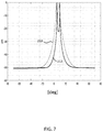
- FIG. 7 is a graph showing beamforming spectra according to an exemplary embodiment
- FIG. 8 is a graph showing a relationship between velocity score and velocity hypothesis according to an exemplary embodiment.
- FIG. 9 is a flowchart illustrating an exemplary embodiment of controlling a vehicle based on an exemplary embodiment of a beamforming method.
- module refers to processing circuitry that may include an application specific integrated circuit (ASIC), an electronic circuit, a processor (shared, dedicated, or group) and memory that executes one or more software or firmware programs, a combinational logic circuit, and/or other suitable components that provide the described functionality.
- ASIC application specific integrated circuit
- processor shared, dedicated, or group
- memory that executes one or more software or firmware programs, a combinational logic circuit, and/or other suitable components that provide the described functionality.
- FIG. 1 shows an exemplary embodiment of a vehicle 10 including an automated driving system 12 and radar system 14 .
- Automated driving system 12 may be operably connected to radar system 14 , and may also include or be operably connected to additional sensors 16 configured to detect a driving environment. Sensors 16 may include a camera, an additional radar system, a LIDAR system, or any combination of these systems.
- automated driving system 12 may calculate a vehicle path plan for vehicle 10 .
- Automated driving system 12 may further include or be operably connected to vehicle controllers 18 configured to control speed, acceleration, braking, steering, or other operations necessary for operating vehicle 10 .
- Automated driving system 12 may control vehicle controllers 18 to operate vehicle 10 according to the calculated vehicle path plan. It will be understood that vehicle 10 may be a fully autonomous vehicle in which automated driving system controls 12 all aspects of the vehicle operation, or vehicle 10 may be a vehicle in which the driver retains some autonomous control and automated driving system 12 is part of a driver assist system configured to assist with a subset of vehicle operations.
- FIG. 2 shows an exemplary embodiment of radar system 14 .
- Radar system 14 may include an antenna 26 structured to transmit a radar signal and receive reflected radar signals from targets.
- Radar system 14 may further include a processor 28 operably connected to antenna 26 and configured to operate on signals received by antenna 26 .
- FIG. 3 shows an exemplary embodiment in which radar system 14 of vehicle 10 may be used to detect a first detection target 20 and a second detection target 22 .
- Detection targets 20 , 22 may represent potential obstacles to operation of the vehicle, such as other vehicles, pedestrians, bicyclists, or landscape features.
- Radar system 14 will have a characteristic angular resolution indicated by angular resolution cell 30 . In other words, even though detection targets 20 , 22 will give multiple reflections radar system 14 will be unable to resolve detection targets 20 , 22 as separate targets due to the angular resolution of radar system 14 , and instead radar system 14 will only detect a single target.
- FIG. 4 shows an exemplary embodiment in which there is relative motion between vehicle 10 , including radar system 14 , and first and second detection targets 20 , 22 .
- the relative motion may be due to motion of the vehicle 10 , motion of detection targets 20 , 22 , or a combination of both, and is represented in FIG. 4 by vector V.
- Detection targets 20 , 22 represent positions relative to vehicle 10 at time t 1
- detection targets 20 ′, 22 ′ represent positions relative to vehicle 10 at time t 2 after the relative motion between vehicle 10 and detection targets 20 , 22 .
- Vector 40 represents the reflection from detection targets 20 , 22 received by radar system 14 at time t 1
- vector 40 ′ represents the reflection from detection targets 20 ′, 22 ′ received by radar system 14 at time t 2 .
- vectors 40 , 40 ′ can be used to individually resolve angular positions of first detection target 20 and second detection target 22 even though first detection target 20 and second detection target 22 are both within an angular resolution cell of radar system 14 .
- FIG. 5 shows an exemplary embodiment of a beamforming method 1000 for individually resolving angular positions of first detection target 20 and second detection target 22 .
- radar system 14 receives a first reflected signal from detection targets 20 , 22 at time t 1 .
- the first reflected signal may be characterized by a first vector 40 having a first arrival angles.
- y 1 is the first vector
- M is the number of reflection angles
- ⁇ m is the m-th index angle of arrival
- ⁇ is the wavelength and x i is the i-th antenna position
- c m is the complex reflector coefficient of the m-th angle of arrival
- v 1 is a first noise factor.
- radar system 14 receives a second reflected signal from detection targets 20 ′, 22 ′ at time t 2 .
- the second reflected signal may be characterized by a second vector 40 having a second set of arrival angles, the second set of arrival angles being equal to the first set of arrival angles plus an angle offset ⁇ .
- Angle offset ⁇ can be calculated by an initial velocity hypothesis for velocity vector V.
- the initial velocity may be calculated from instrumentation of the vehicle, such as a speed sensor, GPS or other suitable instruments, or may be based on a previously calculated velocity hypothesis of vehicle 10 .
- y 2 is the second vector 40 ′
- a( ⁇ m + ⁇ ) is an array response at angle ⁇ m + ⁇
- b m is a the complex reflector coefficient of the reflection from angle ⁇ m + ⁇
- v 2 is a second noise factor
- a translated first vector is calculated by applying the angle offset to the first vector 40 .
- G ( ⁇ ) diag ⁇ e j2 ⁇ / ⁇ x 1 sin ⁇ , . . . ,e j2 ⁇ / ⁇ x N sin ⁇ ⁇ (4);
- N is a number of antenna elements provided in radar system 14
- ⁇ is the wavelength
- x 1 , x 2 , . . . , x N are positions of the N antenna elements.
- a beamforming spectrum is calculated based on the translated first vector y 1 and second vector y 2 .
- translated first vector y 1 and second y 2 should be approximately a sum of the same array response signals a( ⁇ m ) but with different complex reflector coefficients.
- 2 ; Subjected to w H a ( ⁇ ) 1 (5);
- FIG. 6 shows an exemplary embodiment of a beamforming spectrum 200 generated by equation (6).
- graphs 202 , 204 represent Bartlett beamforming spectrum calculated at time t 1 and t 2 without using the translated first vector.
- beamforming spectrum has two very apparent peaks, corresponding to angular locations of first detection target 20 and second detection target 22 .
- FIG. 7 shows an exemplary embodiment of an initial beamforming spectrum 210 calculated with a velocity error compared to an optimal beamforming spectrum 212 with accurate velocity. To achieve the optimal beamforming spectrum 212 , the velocity hypothesis is iteratively adjusted, as described in detail herein.
- a velocity score S E is calculated for the beamforming spectrum calculated in block 116 .
- ⁇ is a normalization factor that can be given by the equation:
- ⁇ ⁇ ⁇ P ⁇ ( ⁇ ) ⁇ 2 ⁇ ⁇ ⁇ ⁇ P ⁇ ( ⁇ ) ⁇ 2 . ( 11 )
- block 120 it is determined whether a minimum velocity score has been identified. If a minimum velocity score has been identified (“Yes” in block 120 ), then the method proceeds to block 124 . If no minimum velocity score has been identified (“No” in block 120 ), then the method proceeds to block 122 .
- the velocity hypothesis used to calculate angle offset ⁇ (and thereby translated first vector y 1 ), is adjusted.
- the adjustment to the velocity hypothesis takes the form of a velocity offset.
- the adjustment may be made by using a coarse grid search over a large span of velocity hypotheses, and then a refined grid search in the vicinity of the most likely candidates.
- the adjustment may be made by an iterative gradient descent, i.e., starting from an initial guess, and each time through choose the next velocity step in a direction that reduces the velocity score.
- FIG. 8 shows an exemplary embodiment of an optimization process of the velocity hypothesis.
- Curve 220 shows a relationship between velocity score and velocity hypothesis in a hypothetical calculation. Each of the dots on curve 220 represents a velocity hypothesis for which the velocity score was calculated. The velocity hypothesis at the minimum of curve 220 is the optimal velocity hypothesis.
- the process returns to block 114 , where a new translated first vector is calculated based on the adjusted velocity hypothesis; block 116 , where a new beamforming spectrum is calculated based on the new translated first vector; and block 118 , where a new velocity score is calculated based on the new beamforming spectrum.
- the velocity hypothesis associated with the minimum velocity score is output as the optimal velocity hypothesis, and the beamforming spectrum associated with the minimum velocity score is output as the optimal beamforming spectrum.
- peaks of the optimal beamforming spectrum are identified and may be output as the angular location of the detection targets 20 , 22 .
- FIG. 9 shows an exemplary embodiment of a method 2000 in which the beamforming method described herein can be used in the context of operating vehicle 10 .
- an optimal velocity hypothesis for vehicle 10 and angular locations of detection targets 20 , 22 are calculated as discussed in detail herein and illustrated in FIG. 5 .
- radar system 14 transmits the optimal velocity hypothesis and angular locations to automated driving system 12 .
- automated driving system 12 adjusts control of vehicle 10 based on the optimal vehicle hypothesis and angular locations of detection targets 20 , 22 .
- the exemplary embodiments described herein result in significant advantages over conventional systems and methods.
- the exemplary embodiments make it possible for a radar system to resolve multiple targets within an angular resolution cell of the radar system.
- the exemplary embodiments functionally improve the angular resolution of a radar system based on relative motion of the radar system.
- the improved angular resolution could allow improved autonomous operation in adverse weather conditions (e.g., rain, snow, fog) and at high speeds.
Abstract
Description
P(θ) is the beamforming spectrum, a(θ) is an array response at angle θ, σ is a regularization factor, I is an identity matrix, superscript H represents a Hermitian transpose, and R is given by the equation R=
wherein N is the number of beamforming angles; and E is given by the equation E=Σθγθ log(γθ). γθ is given by the equation
P(θ) is the beamforming spectrum, a(θ) is an array response at angle θ, σ is a regularization factor, I is the identity matrix, superscript H represents a Hermitian transpose, and R is given by the equation. R=
wherein N is the number of beamforming angles (the beamforming grid points); and E is given by the equation E=−Σθγθ log(γθ). γθ is given by the equation
y 1=Σm=0 M-1 a(θm)c m +v 1 (1);
y 2=Σm=0 M-1 a(θm+Δ)b m +v 2 (2);
G(Δ)=diag{e j2π/λx
P(θ)=minw +w H
R=
S E =E−αZ θ |P(θ)|2 (8).
E=−Σ θγθ log(γθ) (10).
Claims (18)
G(Δ)=diag{e j2π sin Δ/λx
R=
G(Δ)=diag{e j2π/λx
R=
Priority Applications (2)
| Application Number | Priority Date | Filing Date | Title |
|---|---|---|---|
| US16/380,498 US11187782B2 (en) | 2019-04-10 | 2019-04-10 | Radar system with enhanced angular resolution and method for enhancing angular resolution in a radar system |
| DE102020106018.1A DE102020106018A1 (en) | 2019-04-10 | 2020-03-05 | RADAR SYSTEM WITH IMPROVED ANGLE RESOLUTION AND METHOD FOR IMPROVING ANGLE RESOLUTION IN A RADAR SYSTEM |
Applications Claiming Priority (1)
| Application Number | Priority Date | Filing Date | Title |
|---|---|---|---|
| US16/380,498 US11187782B2 (en) | 2019-04-10 | 2019-04-10 | Radar system with enhanced angular resolution and method for enhancing angular resolution in a radar system |
Publications (2)
| Publication Number | Publication Date |
|---|---|
| US20200326408A1 US20200326408A1 (en) | 2020-10-15 |
| US11187782B2 true US11187782B2 (en) | 2021-11-30 |
Family
ID=72613679
Family Applications (1)
| Application Number | Title | Priority Date | Filing Date |
|---|---|---|---|
| US16/380,498 Active 2040-06-25 US11187782B2 (en) | 2019-04-10 | 2019-04-10 | Radar system with enhanced angular resolution and method for enhancing angular resolution in a radar system |
Country Status (2)
| Country | Link |
|---|---|
| US (1) | US11187782B2 (en) |
| DE (1) | DE102020106018A1 (en) |
Families Citing this family (2)
| Publication number | Priority date | Publication date | Assignee | Title |
|---|---|---|---|---|
| CN113009442B (en) * | 2021-02-20 | 2022-12-30 | 森思泰克河北科技有限公司 | Method and device for identifying multipath target of radar static reflecting surface |
| CN114966595A (en) * | 2022-05-20 | 2022-08-30 | 加特兰微电子科技(上海)有限公司 | MIMO sensor, arrival angle approximation degree judging method and target information matching method |
Citations (15)
| Publication number | Priority date | Publication date | Assignee | Title |
|---|---|---|---|---|
| US4845502A (en) * | 1988-04-07 | 1989-07-04 | Carr James L | Direction finding method and apparatus |
| US20050179579A1 (en) * | 2003-12-29 | 2005-08-18 | Pinder Shane D. | Radar receiver motion compensation system and method |
| EP2048514A1 (en) * | 2006-08-04 | 2009-04-15 | Murata Manufacturing Co. Ltd. | Radar target detecting method, and radar device using the method |
| US7714782B2 (en) * | 2004-01-13 | 2010-05-11 | Dennis Willard Davis | Phase arrays exploiting geometry phase and methods of creating such arrays |
| US9007258B2 (en) * | 2011-02-01 | 2015-04-14 | Fujitsu Ten Limited | Radar device and method of calculation of receive power in radar device |
| US20150145716A1 (en) * | 2013-11-22 | 2015-05-28 | Hobbit Wave | Radar using hermetic transforms |
| US20170117946A1 (en) * | 2015-05-13 | 2017-04-27 | Mando Corporation | Apparatus for estimating arrival-angle and apparatus for beam-forming |
| US20180024235A1 (en) * | 2013-10-13 | 2018-01-25 | Oculii Corp | Systems and methods for 4-dimensional radar tracking |
| US20190056506A1 (en) * | 2017-08-17 | 2019-02-21 | GM Global Technology Operations LLC | Doppler measurments to resolve angle of arrival ambiguity of wide aperture radar |
| US20190317191A1 (en) * | 2018-04-11 | 2019-10-17 | Infineon Technologies Ag | Human Detection and Identification in a Setting Using Millimiter-Wave Radar |
| US10509119B2 (en) * | 2018-01-30 | 2019-12-17 | Oculii Corp. | Systems and methods for virtual aperature radar tracking |
| US10620304B2 (en) * | 2013-08-28 | 2020-04-14 | Aveillant Limited | Radar system and associated apparatus and methods |
| US20200116850A1 (en) * | 2018-10-16 | 2020-04-16 | Infineon Technologies Ag | Estimating Angle of Human Target Using mmWave Radar |
| US20200300965A1 (en) * | 2019-03-18 | 2020-09-24 | Nxp Usa, Inc. | Distributed Aperture Automotive Radar System |
| US20200300995A1 (en) * | 2019-03-18 | 2020-09-24 | Nxp Usa, Inc. | Distributed Aperture Automotive Radar System with Alternating Master Radar Devices |
-
2019
- 2019-04-10 US US16/380,498 patent/US11187782B2/en active Active
-
2020
- 2020-03-05 DE DE102020106018.1A patent/DE102020106018A1/en active Pending
Patent Citations (22)
| Publication number | Priority date | Publication date | Assignee | Title |
|---|---|---|---|---|
| US4845502A (en) * | 1988-04-07 | 1989-07-04 | Carr James L | Direction finding method and apparatus |
| US20050179579A1 (en) * | 2003-12-29 | 2005-08-18 | Pinder Shane D. | Radar receiver motion compensation system and method |
| US7714782B2 (en) * | 2004-01-13 | 2010-05-11 | Dennis Willard Davis | Phase arrays exploiting geometry phase and methods of creating such arrays |
| EP2048514A1 (en) * | 2006-08-04 | 2009-04-15 | Murata Manufacturing Co. Ltd. | Radar target detecting method, and radar device using the method |
| US20090231182A1 (en) * | 2006-08-04 | 2009-09-17 | Murata Manufacturing Co., Ltd. | Radar Target Detecting Method, and Appartus Using the Target Detecting Method |
| US7898460B2 (en) * | 2006-08-04 | 2011-03-01 | Murata Manufacturing Co., Ltd. | Radar target detecting method, and apparatus using the target detecting method |
| US9007258B2 (en) * | 2011-02-01 | 2015-04-14 | Fujitsu Ten Limited | Radar device and method of calculation of receive power in radar device |
| US10620304B2 (en) * | 2013-08-28 | 2020-04-14 | Aveillant Limited | Radar system and associated apparatus and methods |
| US10222463B2 (en) * | 2013-10-13 | 2019-03-05 | Oculii Corp. | Systems and methods for 4-dimensional radar tracking |
| US9939522B2 (en) * | 2013-10-13 | 2018-04-10 | Oculii Corp | Systems and methods for 4-dimensional radar tracking |
| US20180188365A1 (en) * | 2013-10-13 | 2018-07-05 | Oculii Corp | Systems and methods for 4-dimensional radar tracking |
| US20180024235A1 (en) * | 2013-10-13 | 2018-01-25 | Oculii Corp | Systems and methods for 4-dimensional radar tracking |
| WO2015105592A2 (en) * | 2013-11-22 | 2015-07-16 | Hobbit Wave | Radar using hermetic transforms |
| US9829568B2 (en) * | 2013-11-22 | 2017-11-28 | VertoCOMM, Inc. | Radar using hermetic transforms |
| US20150145716A1 (en) * | 2013-11-22 | 2015-05-28 | Hobbit Wave | Radar using hermetic transforms |
| US20170117946A1 (en) * | 2015-05-13 | 2017-04-27 | Mando Corporation | Apparatus for estimating arrival-angle and apparatus for beam-forming |
| US20190056506A1 (en) * | 2017-08-17 | 2019-02-21 | GM Global Technology Operations LLC | Doppler measurments to resolve angle of arrival ambiguity of wide aperture radar |
| US10509119B2 (en) * | 2018-01-30 | 2019-12-17 | Oculii Corp. | Systems and methods for virtual aperature radar tracking |
| US20190317191A1 (en) * | 2018-04-11 | 2019-10-17 | Infineon Technologies Ag | Human Detection and Identification in a Setting Using Millimiter-Wave Radar |
| US20200116850A1 (en) * | 2018-10-16 | 2020-04-16 | Infineon Technologies Ag | Estimating Angle of Human Target Using mmWave Radar |
| US20200300965A1 (en) * | 2019-03-18 | 2020-09-24 | Nxp Usa, Inc. | Distributed Aperture Automotive Radar System |
| US20200300995A1 (en) * | 2019-03-18 | 2020-09-24 | Nxp Usa, Inc. | Distributed Aperture Automotive Radar System with Alternating Master Radar Devices |
Also Published As
| Publication number | Publication date |
|---|---|
| US20200326408A1 (en) | 2020-10-15 |
| DE102020106018A1 (en) | 2020-10-15 |
Similar Documents
| Publication | Publication Date | Title |
|---|---|---|
| KR102099851B1 (en) | Method of clustering targets detected by automotive radar system and apparatus for the same | |
| JP6567832B2 (en) | Radar system, radar signal processing apparatus, vehicle travel control apparatus and method, and computer program | |
| US9030349B2 (en) | Moving object detection system | |
| US20070008211A1 (en) | Vehicle mounted radar apparatus | |
| US20210382165A1 (en) | Method and apparatus for processing radar signal by correcting phase distortion | |
| US20160363651A1 (en) | Apparatus for processing signals of radar and method for processing signals thereof | |
| US10969466B2 (en) | Sliding window integration scheme for object detection in a radar system | |
| US20180128916A1 (en) | Object detection in multiple radars | |
| US11187782B2 (en) | Radar system with enhanced angular resolution and method for enhancing angular resolution in a radar system | |
| US20190086512A1 (en) | Method and apparatus for vehicular radar calibration | |
| US11047971B2 (en) | Radar system and control method for use in a moving vehicle | |
| US10345439B2 (en) | Object detection in multiple radars | |
| US10705186B2 (en) | Apparatus for detecting axial misalignment | |
| US20210405186A1 (en) | Obstacle detection system and method using distance sensor | |
| CN112098965B (en) | Carrier attitude angle resolving method based on millimeter wave radar | |
| CN110806580A (en) | Vibration mitigation in radar systems on mobile platforms | |
| CN107783130B (en) | Signal processing method of unmanned vehicle complex environment anti-collision system based on combined waveform | |
| US11181614B2 (en) | Antenna array tilt and processing to eliminate false detections in a radar system | |
| CN110940973B (en) | Angle measurement method and device for radar target detection | |
| CN116106894A (en) | Target tracking method, device and storage medium based on 5D millimeter wave radar | |
| US20220260701A1 (en) | Method and Device for Determining an Angle of a Target Object | |
| US20230384440A1 (en) | Super-Resolution Based on Iterative Multiple-Source Angle-of-Arrival Estimation | |
| CN114488111A (en) | Estimating vehicle speed using radar data | |
| EP3761054A1 (en) | Sensor calibration based on strings of detections | |
| US11360206B2 (en) | Detection device and detection method thereof |
Legal Events
| Date | Code | Title | Description |
|---|---|---|---|
| AS | Assignment |
Owner name: GM GLOBAL TECHNOLOGY OPERATIONS LLC, MICHIGAN Free format text: ASSIGNMENT OF ASSIGNORS INTEREST;ASSIGNORS:BIALER, ODED;KOLPINIZKI, SAMMY;REEL/FRAME:048849/0536 Effective date: 20190408 |
|
| FEPP | Fee payment procedure |
Free format text: ENTITY STATUS SET TO UNDISCOUNTED (ORIGINAL EVENT CODE: BIG.); ENTITY STATUS OF PATENT OWNER: LARGE ENTITY |
|
| STPP | Information on status: patent application and granting procedure in general |
Free format text: NOTICE OF ALLOWANCE MAILED -- APPLICATION RECEIVED IN OFFICE OF PUBLICATIONS |
|
| STPP | Information on status: patent application and granting procedure in general |
Free format text: PUBLICATIONS -- ISSUE FEE PAYMENT VERIFIED |
|
| STCF | Information on status: patent grant |
Free format text: PATENTED CASE |