EP3640417A1 - Schlüssel für einen schliesszylinder - Google Patents
Schlüssel für einen schliesszylinder Download PDFInfo
- Publication number
- EP3640417A1 EP3640417A1 EP18200479.6A EP18200479A EP3640417A1 EP 3640417 A1 EP3640417 A1 EP 3640417A1 EP 18200479 A EP18200479 A EP 18200479A EP 3640417 A1 EP3640417 A1 EP 3640417A1
- Authority
- EP
- European Patent Office
- Prior art keywords
- key
- wear indicator
- wear
- shaft
- locking
- Prior art date
- Legal status (The legal status is an assumption and is not a legal conclusion. Google has not performed a legal analysis and makes no representation as to the accuracy of the status listed.)
- Granted
Links
Images


Classifications
-
- E—FIXED CONSTRUCTIONS
- E05—LOCKS; KEYS; WINDOW OR DOOR FITTINGS; SAFES
- E05B—LOCKS; ACCESSORIES THEREFOR; HANDCUFFS
- E05B19/00—Keys; Accessories therefor
Definitions
- the invention relates to a key for a locking cylinder with the features of the preamble of claim 1.
- the invention relates to a locking system with the features of the independent claim.
- Keys for a lock cylinder of the type mentioned are known from the prior art, for example from DE 1 137 341 A1 .
- Such keys have a key chalk and a key shaft extending from the key chalk, on which incisions for aligning tumblers are formed, which are provided on an associated locking cylinder.
- Such Keys have proven their worth, as they offer a high level of security for consumers due to the large number of individual locking combinations.
- the invention has for its object to enable long-term reliable operation in lock cylinders. It is desirable that a required key exchange is signaled to a user in good time.
- the key is characterized in that the key shaft has a wear indicator for signaling or indicating the state of wear of the key.
- the wear indicator is in particular set up in such a way that when a key is worn, a user is signaled that the key is worn out or that the key needs to be replaced (preventive replacement procurement).
- Such an embodiment has the advantage that a sudden functional failure of a locking cylinder caused by key wear can be largely avoided, since the wear indicator signals when the key is worn that a key exchange is required. Since the key has the softer material in the usual material combinations of key and lock cylinder, the required key exchange is indicated in good time. If the worn key is replaced by a new key, the operation of a locking cylinder can be maintained permanently. This contributes to the safe operation of a locking cylinder and also complete locking systems.
- the key can be designed as a key for a profile cylinder (profile cylinder key) and the locking cylinder can be designed as a profile cylinder.
- the key shaft can go along an axial direction (longitudinal shaft direction) away from the key.
- the key shaft can have a shaft section provided without incisions (“key shaft neck” or “key shaft stalk”) and then a shaft section provided with incisions for aligning tumblers.
- the wear indicator is designed in such a way that a key exchange is signaled when the lock cylinder (belonging to the key) can still be operated by the key for a certain remaining time (the lock cylinder has not yet failed). This favors timely replacement or timely replacement of the key.
- a necessary key exchange can then be signaled when a wear limit value is exceeded, for example 70 percent of the maximum possible wear.
- a wear limit value for example 70 percent of the maximum possible wear.
- the wear indicator can be, for example, in its height (elevation) or depth (depression) relative to a reference surface, for example an end face of a key tip, in accordance with the wear limit value be measured. If the elevation or the deepening is no longer recognizable, the defined wear limit value has been exceeded.
- the wear indicator can be designed independently of the locking features incorporated into the key. This means that the wear indicator is not realized by a locking feature itself, but by a feature that is separate from it and serves as a wear indicator. This favors the perception of the wear indicator and allows the wear indicator to be designed independently of any locking features.
- the wear indicator can be designed separately for incisions and / or profiles or profile features of the key shaft.
- the wear indicator can advantageously be designed as a haptic wear indicator and / or as an optical wear indicator. This allows the wearer to be signaled to the key user by haptic and / or optical means.
- a haptic wear indicator can be designed as a wear feature on the key shaft, which can be felt by the user, for example by means of a "fingernail test”.
- An optical wear indicator can have an optical (wear) feature which differs in particular from the key shank or the end face and which visually signals the wear state to a key user, for example by means of a micrograph, a matt surface or a color coding.
- the wear indicator can have an elevation formed on the key shaft (raised relative to the key shaft or to the key shaft profile) or a depression (deepened relative to the key shaft or key shaft profile). This allows a wear indicator to be provided in a structurally advantageous manner since no further components are required. In this way, the elevation or depression can be made of the same material and in one piece to form the key shaft.
- the wear indicator can expediently have a color coding. This enhances the perception of the wear indicator by highlighting it against the key shaft.
- the color coding can be designed in such a way that it also decreases with the material removal on the key shaft due to wear.
- the color coding can be designed in several stages, for example by means of several, preferably different, color layers. This means that a two-stage traffic light system (green-red) or a three-stage traffic light system (green-orange-red) can be implemented.
- the color green can indicate minor wear, the color orange an already increased wear and the color red a critical wear.
- the color red signals to a key user that an exchange key must be obtained urgently.
- the color coding can be arranged, for example, in a depression or between two elevations of a wear indicator. If the indentation or the elevations relative to their reference surface are no longer recognizable due to wear, the color coding is also removed accordingly.
- the wear indicator can be formed or arranged on the face of the key tip of the key shaft.
- the state of wear of the key tip or the end face of the key tip can thereby be signaled.
- the key tip is of great importance for the operation of the key and the locking cylinder, since when the key is inserted into the locking channel it first comes into contact with components of the locking cylinder and is subject to high wear due to the comparatively long insertion path in the locking channel.
- the key tip also actuates the coupling element or the coupling of the locking cylinder, which couples a cylinder core of the locking cylinder to the locking bit. If the tip of the key is worn too much, it is no longer possible to actuate the locking bar, since the "spinning" described above occurs.
- the key shaft can have incisions for aligning tumblers of a locking cylinder.
- the wear indicator can be formed on or between incisions on the key shaft, in particular on flanks of the incisions, for example on two opposite flanks of an incision of the key shaft. This can be used to signal the state of wear on the notches for aligning the tumblers.
- the incisions on the key shaft are also of great importance for the operation of the key and locking cylinder, since these shift the core pins in the locking cylinder into the release position. If the incisions on the key shaft are too worn out, not all of the core pins can be moved to the release position, so that the cylinder core in the locking cylinder is not released and therefore cannot be turned.
- Such a wear indicator on the incisions can be provided as an alternative or in addition to a wear indicator on the key tip. If there is a wear indicator at the incisions and a wear indicator at the key tip, a particularly meaningful signaling of the state of wear of the key is possible, since wear at the incisions or at the key tip can be the decisive factor for a necessary key exchange.
- the key can be designed as a conventional lock cylinder key or as a reversible key.
- the detection of the state of wear is of great importance for both types of keys.
- a conventional locking cylinder key (beard key) can only be oriented in one direction in the locking channel associated lock cylinder are introduced.
- a reversible key can be inserted into the key channel of an associated locking cylinder in at least two different orientations.
- Figure 1 shows a key known from the prior art for a locking cylinder, which is designated overall by the reference number 1 (key 1 is shown in the "overhead position").
- the key 1 has a key chord 2 and a key shaft 4 which extends away from the key chord 2 along an axial direction 3.
- the key shaft 4 has a key tip 5 at the free end. Notches 6 for actuating the tumblers of an associated locking cylinder are formed on the key shaft 4 (not shown in detail).
- the key 1 is designed as a conventional lock cylinder key (beard key).
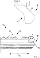
- FIG. 2 shows a key, designated overall by reference number 10, for a locking cylinder according to the present application (only partially shown).
- the structure of the key 10 basically corresponds to that in FIG Figure 1 shown key 1.
- the key 10 has a key chord (not shown) and a key shaft 16 extending away from the key chord along an axial direction 14.
- the key shaft 16 has a key tip 18 at the free end.
- the end face or end face of the key tip 18 is designated by the reference symbol 19 (end face or end face 19).
- Incisions 20 for aligning tumblers of an associated locking cylinder are also provided on the key shaft 16 (provided only once with reference numerals).
- the key 10 is designed as a conventional lock cylinder key (beard key).
- the key shaft 16 also has a wear indicator 22 for signaling the state of wear of the key 10.
- the wear indicator 22 is formed on the end face at the key tip 18 of the key shaft 16.
- the wear indicator 22 has two recesses 24 formed on the key shaft 16, which are recessed relative to the end face 19 (see enlarged view) "Detail A"). The depressions 24 are spaced apart from one another.
- the wear state of the key shaft 16 can be seen in particular on the key tip 18 on the basis of the depressions 24. If the recesses 24 are not or only barely perceptible to the key user, for example optically and / or haptically, the state of wear signals the key user that an exchange of the key 10 is necessary.
- the wear indicator 22 can be designed such that a worn-out state, that is to say a necessary key exchange, is signaled when the lock cylinder associated with the key 10 can still be actuated by the key 10. A worn out state or a necessary key exchange can then be signaled when a defined wear limit value is exceeded, for example 70 percent of the maximum possible wear, as explained above.
- the depths of the depressions 24 correspond to the defined wear limit value. If the recesses 24 are no longer or only barely perceptible to the key user, the defined wear limit value has been reached and the key 10 should be replaced.
- the wear indicator 22 is formed independently of the locking features incorporated in the key 10, for example separately from incisions or profiles or profile features.
- the wear indicator 22 By designing the wear indicator 22 with depressions 24, the wear indicator 22 is initially designed as a haptic wear indicator 22, since the depressions 24 can be felt haptically, for example by a "fingernail test" by the key user.
- the wear indicator 22 By designing the wear indicator 22 with indentations 24, the wear indicator 22 is also designed as an optical wear indicator 22, since the indentations 24 can also be recognized optically, for example by the shadow resulting in the indentations 24.
- the perceptibility of the optical wear indicator 22 can be further improved by forming in the recesses 24 a feature that is optically different from the end face 19, for example a micrograph, a matt surface or a color coding.
- the wear indicator 22 can have a color coding, possibly a multi-level color coding (“traffic light display”), as explained above.
- the key 10 In addition to the wear indicator 22 on the key tip 18, it has a (further) wear indicator 26 which is formed on an incision 20 for aligning tumblers of an associated locking cylinder.
- the wear indicator 26 is formed on the flanks 28 of the incision 20 (see enlarged view “detail B”).
- the wear indicator 26 has two depressions 30 formed on the flanks, which are recessed relative to the flanks 28 (see enlarged view "Detail A"). In each case a recess 30 is arranged on a flank 28, in particular symmetrically with respect to the incision 20.
- the state of wear of an incision 20 in the key shaft 16 can be seen on the basis of the depressions 30. If the recesses 30 are not or only barely perceptible to the key user, for example optically and / or haptically, the state of wear signals the key user that an exchange of the key 10 is necessary.
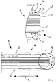
- Figure 4 shows another key for a lock cylinder according to the present application, which is designated overall by the reference numeral 10 (only partially shown).
- the key 10 is designed as a reversible key.
- the key 10 has a key chalk (not shown) and a key shaft 16 which extends away from the key chord along an axial direction 14.
- the key shaft 16 has a key tip 18 at the free end.
- the end face of the key tip 18 is designated by the reference symbol 19 (end face or end face 19).
- incisions 20 are provided on both sides for aligning tumblers of an associated locking cylinder (provided only once with reference numerals).
- the end face 19 has a central section 19 'which is oriented orthogonally to the axial direction 14 and on both sides in each case a section 19' 'which is adjacent and angled to the central section 19' (cf. enlarged view "Detail C").
- the key shaft 16 also has a wear indicator 22 for signaling the state of wear of the key 10.
- the wear indicator 22 is formed on the end face at the key tip 18 of the key shaft 16.
- the Wear indicator 22 has two projections 32, which are formed on key shank 16 and are spaced apart from one another and are raised relative to end face 19 (see enlarged view "Detail C").
- the elevations 32 are each arranged in the angled sections 19 ′′ of the end face 19. Between two raised areas 32 there is an intermediate space 34 (as part of the angled section 19 ′′).
- the level 36 of the floor 36 of the intermediate room 34 can correspond to the sections 19 ′′ (floor 36 of the intermediate room 34 and the relevant angled section 19 ′′ lie on one level).
- the state of wear of the key shaft 16 can be recognized in particular at the key tip 18. If the elevations 32 are not or only barely perceptible to the key user, for example optically and / or haptically, the state of wear signals the key user that an exchange of the key 10 is necessary.
- the wear indicator 22 can be designed in such a way that a worn condition or a necessary key exchange is signaled when a defined wear limit value is exceeded, for example 70 percent of the maximum possible wear, as explained above.
- a defined wear limit value for example 70 percent of the maximum possible wear, as explained above.
- the elevations 32 in their height correspond to the defined wear limit.
- the wear indicator 22 is designed as a haptic wear indicator 22 and also as an optical wear indicator 22.
- the elevations 32 can be felt haptically, for example by a "fingernail test" by the key user.
- the elevations 32 can also be recognized optically, for example by the shadow that results between the elevations 32.
- the perceptibility of the wear indicator 22 can be improved further, between the elevations 32 a feature which is optically different from the end face 19 or the elevations 32 is formed, for example a micrograph, a matt surface or a color coding.
- the wear indicator 22 can have a color coding, possibly a multi-level color coding, as explained above. Such a color coding can be formed between the elevations 32.
Landscapes
- Lock And Its Accessories (AREA)
Abstract
Description
- Die Erfindung betrifft einen Schlüssel für einen Schließzylinder mit den Merkmalen des Oberbegriffs von Anspruch 1. Zudem betrifft die Erfindung ein Schließsystem mit den Merkmalen des nebengeordneten Anspruchs.
- Schlüssel für einen Schließzylinder der eingangs genannten Art sind aus dem Stand der Technik bekannt, bspw. aus der
DE 1 137 341 A1 . Derartige Schlüssel weisen eine Schlüsselreide und einen sich von der Schlüsselreide erstreckenden Schlüsselschaft auf, an dem Einschnitte zum Ausrichten von Zuhaltungen ausgebildet sind, die an einem zugehörigen Schließzylinder vorgesehen sind. Derartige Schlüssel haben sich bewährt, da diese u.a. aufgrund der hohen Anzahl individueller Schließkombinationen für den Verbraucher eine hohe Sicherheit bieten. - Allerdings besteht Raum für Optimierungen. So hat sich in der Praxis gezeigt, dass ein Schlüssel für einen Schließzylinder einem nicht unerheblichen Verschleiß unterliegt. Dieser Schlüsselverschleiß kann dazu führen, dass die Kupplung in einem doppelten Schließzylinder (Doppelzylinder), die einen Zylinderkern mit dem Schließbart koppelt, nicht mehr hinreichend betätigt werden kann. Dann kommt es zu einem "Durchdrehen" des Schließzylinders, da sich der Zylinderkern mit dem Schlüssel drehen lässt, der Schließbart jedoch nicht zugekuppelt wird. Zudem kann Schlüsselverschleiß an den Einschnitten am Schlüsselschaft dazu führen, dass nicht mehr sämtliche Zuhaltungen (Kernstifte) eines Schließzylinders in Freigabestellung verlagert werden können. Somit ist ein zuverlässiger Betrieb eines Schließzylinders nicht dauerhaft gewährleistet, zumal sich der Funktionsausfall nicht ankündigt und je nach Häufigkeit der Betätigung von Schlüssel und Schließzylinder zu unterschiedlichen Zeitpunkten auftritt.
- Der Erfindung liegt die Aufgabe zugrunde, bei Schließzylindern einen dauerhaft zuverlässigen Betrieb zu ermöglichen. Dabei ist wünschenswert, dass einem Anwender rechtzeitig ein erforderlicher Austausch eines Schlüssels signalisiert wird.
- Die Erfindung löst diese Aufgabe durch einen Schlüssel mit den Merkmalen von Anspruch 1. Danach zeichnet sich der Schlüssel dadurch aus, dass der Schlüsselschaft einen Verschleißindikator zur Signalisierung oder zur Anzeige des Verschleißzustands des Schlüssels aufweist.
- Der Verschleißindikator ist insbesondere derart eingerichtet, dass einem Anwender bei verschlissenem Schlüssel signalisiert wird, dass der Schlüssel verschlissen bzw. ein Austausch des Schlüssels erforderlich ist (vorbeugende Ersatzbeschaffung).
- Eine solche Ausgestaltung hat den Vorteil, dass ein durch Schlüsselverschleiß bedingter plötzlicher Funktionsausfall eines Schließzylinders weitgehend vermieden werden kann, da der Verschleißindikator bei verschlissenem Schlüssel signalisiert, dass ein Schlüsselaustausch erforderlich ist. Da bei den üblichen Materialpaarungen von Schlüssel und Schließzylinder der Schlüssel über das weichere Material verfügt, wird der erforderliche Schlüsselaustausch rechtzeitig angezeigt. Wird der verschlissene Schlüssel durch einen neuen Schlüssel ersetzt, kann der Betrieb eines Schließzylinders dauerhaft aufrechterhalten bleiben. Dies trägt zu einem sicheren Betrieb eines Schließzylinders und auch kompletter Schließanlagen bei.
- Der Schlüssel kann als Schlüssel für einen Profilzylinder ausgebildet sein (Profilzylinderschlüssel) und der Schließzylinder kann als Profilzylinder ausgebildet sein. Unabhängig davon kann sich der Schlüsselschaft entlang einer Axialrichtung (Schaftlängsrichtung) von der Schlüsselreide weg erstrecken.
- Der Schlüsselschaft kann an seinem der Schlüsselreide zugewandten Ende einen ohne Einschnitte versehenen Schaftabschnitt aufweisen ("Schlüsselschafthals" oder "Schlüsselschafthalm") und hieran anschließend einen mit Einschnitten zur Ausrichtung von Zuhaltungen versehenen Schaftabschnitt.
- Im Rahmen einer bevorzugten Ausgestaltung ist der Verschleißindikator derart ausgebildet, dass ein Schlüsselaustausch bereits dann signalisiert wird, wenn der (zum Schlüssel zugehörige) Schließzylinder noch über eine gewisse Restdauer durch den Schlüssel betätigbar ist (Funktionsausfall des Schließzylinders liegt noch nicht vor). Dies begünstigt eine rechtzeitige Ersatzbeschaffung oder einen rechtzeitigen Austausch des Schlüssels.
- Dabei kann ein erforderlicher Schlüsselaustausch dann signalisiert werden, wenn ein Verschleißgrenzwert überschritten wird, bspw. 70 Prozent des maximal möglichen Verschleißes. Dies kann derart definiert sein, dass der maximal mögliche Verschleiß 100 Prozent beträgt und bei einem Verschleiß von mehr als 100 Prozent eine Betätigung des Schließzylinders nicht mehr möglich ist. Hierzu kann der Verschleißindikator bspw. in seiner Höhe (Erhebung) oder seiner Tiefe (Vertiefung) relativ zu einer Bezugsfläche, bspw. einer Stirnfläche einer Schlüsselspitze, entsprechend dem Verschleißgrenzwert bemessen sein. Ist die Erhebung oder die Vertiefung nicht mehr erkennbar, ist der definierte Verschleißgrenzwert überschritten.
- Im Konkreten kann der Verschleißindikator unabhängig von dem Schlüssel einverleibten Schließmerkmalen ausgebildet sein. Dies bedeutet, dass der Verschleißindikator nicht durch ein Schließmerkmal selbst realisiert ist, sondern durch ein hiervon separat ausgebildetes und als Verschleißindikator dienendes Merkmal. Dies begünstigt die Wahrnehmung des Verschleißindikators und erlaubt eine Ausgestaltung des Verschleißindikators unabhängig von etwaigen Schließmerkmalen. Bspw. kann der Verschleißindikator separat zu Einschnitten und/oder Profilen bzw. Profilmerkmalen des Schlüsselschafts ausgebildet sein.
- In vorteilhafter Weise kann der Verschleißindikator als haptischer Verschleißindikator und/oder als optischer Verschleißindikator ausgebildet sein. Hiermit kann die Signalisierung des Verschleißzustandes auf haptischem Wege und/oder auf optischem Wege an den Schlüsselnutzer erfolgen. Ein haptischer Verschleißindikator kann als ein Verschleißmerkmal am Schlüsselschaft ausgebildet sein, welches durch den Anwender ertastbar ist, bspw. mittels eines "Fingernageltests". Ein optischer Verschleißindikator kann ein optisches, sich insbesondere von dem Schlüsselschaft oder der Stirnfläche unterscheidendes (Verschleiß-)Merkmal aufweisen, das einem Schlüsselnutzer den Verschleißzustand optisch signalisiert, bspw. mittels einem Schliffbild, einer matten Oberfläche oder einer Farbkodierung.
- Im Rahmen einer bevorzugten Ausgestaltung kann der Verschleißindikator eine am Schlüsselschaft ausgebildete Erhebung (relativ zum Schlüsselschaft bzw. zum Schlüsselschaftprofil erhaben) oder Vertiefung (relativ zum Schlüsselschaft bzw. zum Schlüsselschaftprofil vertieft) aufweisen. Hiermit kann auf konstruktiv günstige Weise ein Verschleißindikator bereitgestellt werden, da keine weiteren Komponenten erforderlich sind. So können die Erhebung oder Vertiefung materialeinheitlich und einstückig zum Schlüsselschaft ausgebildet sein.
- In zweckmäßiger Weise kann der Verschleißindikator eine Farbkodierung aufweisen. Hiermit wird die Wahrnehmung des Verschleißindikators durch farbliche Hervorhebung gegenüber dem Schlüsselschaft begünstigt. Die Farbkodierung kann derart ausgebildet sein, dass diese mit dem durch Verschleiß bedingten Materialabtrag am Schlüsselschaft ebenfalls abnimmt. Die Farbkodierung kann mehrstufig ausgebildet sein, bspw. durch mehrere, vorzugsweise unterschiedliche Farbschichten. Somit lässt sich ein zweistufiges Ampelsystem (grün-rot) oder ein dreistufiges Ampelsystem (grün-orange-rot) realisieren.
- Dabei kann die Farbe grün einen geringen Verschleiß, die Farbe orange einen bereits erhöhten Verschleiß und die Farbe rot einen kritischen Verschleiß signalisieren. Dabei signalisiert die Farbe rot einem Schlüsselnutzer, dass dringend ein Austauschschlüssel beschafft werden muss. Die Farbkodierung kann bspw. in einer Vertiefung oder zwischen zwei Erhebungen eines Verschleißindikators angeordnet sein. Sind die Vertiefung bzw. die Erhebungen relativ zu deren Bezugsfläche verschleißbedingt nicht mehr erkennbar, so ist auch die Farbkodierung entsprechend abgetragen.
- Im Konkreten kann der Verschleißindikator stirnseitig an der Schlüsselspitze des Schlüsselschafts ausgebildet bzw. angeordnet sein. Dadurch kann der Verschleißzustand der Schlüsselspitze bzw. der Stirnfläche der Schlüsselspitze signalisiert werden. Die Schlüsselspitze ist für den Betrieb von Schlüssel und Schließzylinder von hoher Bedeutung, da diese beim Einstecken des Schlüssels in den Schließkanal als erstes mit Komponenten des Schließzylinders in Kontakt gelangt und durch den vergleichsweise langen Einschubweg im Schließkanal einem hohen Verschleiß unterliegt. Zudem betätigt die Schlüsselspitze bei einem doppelten Schließzylinder (Doppelzylinder) das Kupplungselement bzw. die Kupplung des Schließzylinders, welche einen Zylinderkern des Schließzylinders mit dem Schließbart kuppelt. Ist die Schlüsselspitze zu stark verschlissen, ist eine Betätigung des Schließbarts nicht mehr möglich, da es zu dem oben bereits beschriebenen "Durchdrehen" kommt.
- Der Schlüsselschaft kann Einschnitte zur Ausrichtung von Zuhaltungen eines Schließzylinders aufweisen. Alternativ oder ergänzend kann der Verschleißindikator an oder zwischen Einschnitten am Schlüsselschaft ausgebildet sein, insbesondere an Flanken der Einschnitte, bspw. an zwei gegenüberliegenden Flanken eines Einschnitts des Schlüsselschafts. Hiermit kann der Verschleißzustand an den Einschnitten zur Ausrichtung der Zuhaltungen signalisiert werden. Auch die Einschnitte am Schlüsselschaft sind für den Betrieb von Schlüssel und Schließzylinder von hoher Bedeutung, da diese die Kernstifte im Schließzylinder in Freigabestellung verlagern. Sind die Einschnitte am Schlüsselschaft zu sehr verschlissen, können nicht mehr sämtliche Kernstifte in Freigabestellung verlagert werden, so dass der Zylinderkern im Schließzylinder nicht freigegeben ist und somit nicht gedreht werden kann.
- Ein solcher Verschleißindikator an den Einschnitten kann alternativ oder ergänzend zu einem Verschleißindikator an der Schlüsselspitze vorgesehen sein. Sind ein Verschleißindikator an den Einschnitten und ein Verschleißindikator an der Schlüsselspitze vorhanden, ist eine besonders aussagekräftige Signalisierung des Verschleißzustandes des Schlüssels möglich, da ein Verschleiß an den Einschnitten oder an der Schlüsselspitze den Ausschlag für einen erforderlichen Schlüsselaustausch geben kann.
- Im Konkreten kann der Schlüssel als herkömmlicher Schließzylinderschlüssel oder als Wendeschlüssel ausgebildet sein. Die Erkennung des Verschleißzustandes ist bei beiden Schlüsselarten von hoher Bedeutung. Ein herkömmlicher Schließzylinderschlüssel (Bartschlüssel) kann nur in einer Orientierung in den Schließkanal eines zugehörigen Schließzylinders eingeführt werden. Ein Wendeschlüssel kann in zumindest zwei unterschiedlichen Orientierungen in den Schlüsselkanal eines zugehörigen Schließzylinders eingeführt werden.
- Die eingangs genannte Aufgabe wird auch durch ein Schließsystem mit den Merkmalen des nebengeordneten Anspruchs gelöst. Hinsichtlich der damit erzielbaren Vorteile sei auf die diesbezüglichen Ausführungen im Zusammenhang mit Anspruch 1 verwiesen.
- Zur weiteren Ausgestaltung des Schließsystems können die im Zusammenhang mit dem Schlüssel erläuterten oder die in der nachfolgenden Figurenbeschreibung beschriebenen Maßnahmen dienen.
- Die Erfindung wird im Folgenden anhand der Figuren näher erläutert, wobei gleiche oder funktional gleiche Elemente mit identischen Bezugszeichen versehen sind, ggf. jedoch lediglich einmal. Es zeigen:
- Figur 1
- einen Schlüssel für einen Schließzylinder gemäß Stand der Technik;
- Figur 2
- eine erste Ausführungsform eines Schlüssels für einen Schließzylinder gemäß der vorliegenden Anmeldung in einer teilweisen Seitenansicht mit Blick auf den Schlüsselschaft und einer vergrößerten Detailansicht (Detail A);
- Figur 3
- eine weitere Ausführungsform eines Schlüssels für einen Schließzylinder gemäß der vorliegenden Anmeldung in einer teilweisen Seitenansicht mit Blick auf den Schlüsselschaft und einer vergrößerten Detailansicht (Detail B); und
- Figur 4
- eine weitere Ausführungsform eines Schlüssels für einen Schließzylinder gemäß der vorliegenden Anmeldung in einer teilweisen Seitenansicht mit Blick auf den Schlüsselschaft und einer vergrößerten Detailansicht (Detail C).
-
Figur 1 zeigt einen aus dem Stand der Technik bekannten Schlüssel für einen Schließzylinder, der insgesamt mit dem Bezugszeichen 1 bezeichnet ist (Schlüssel 1 ist in "Überkopf-Stellung" abgebildet). Der Schlüssel 1 weist eine Schlüsselreide 2 und einen sich von der Schlüsselreide 2 entlang einer Axialrichtung 3 weg erstreckenden Schlüsselschaft 4 auf. - Der Schlüsselschaft 4 weist am freien Ende eine Schlüsselspitze 5 auf. Am Schlüsselschaft 4 sind Einschnitte 6 zur Betätigung von Zuhaltungen eines zugehörigen Schließzylinders ausgebildet (nicht im Einzelnen dargestellt). Der Schlüssel 1 ist als herkömmlicher Schließzylinderschlüssel (Bartschlüssel) ausgebildet.
-
Figur 2 zeigt einen insgesamt mit dem Bezugszeichen 10 bezeichneten Schlüssel für einen Schließzylinder gemäß der vorliegenden Anmeldung (lediglich teilweise dargestellt). - Der Schlüssel 10 entspricht in seinem Aufbau grundsätzlich dem in
Figur 1 gezeigten Schlüssel 1. So weist der Schlüssel 10 eine Schlüsselreide (nicht dargestellt) und einen sich von der Schlüsselreide entlang einer Axialrichtung 14 weg erstreckenden Schlüsselschaft 16 auf. Der Schlüsselschaft 16 weist am freien Ende eine Schlüsselspitze 18 auf. Die Stirnseite oder Stirnfläche der Schlüsselspitze 18 ist mit dem Bezugszeichen 19 bezeichnet (Stirnseite oder Stirnfläche 19). - Am Schlüsselschaft 16 sind zudem Einschnitte 20 zur Ausrichtung von Zuhaltungen eines zugehörigen Schließzylinders vorgesehen (lediglich einmal mit Bezugszeichen versehen). Der Schlüssel 10 ist als herkömmlicher Schließzylinderschlüssel (Bartschlüssel) ausgebildet.
- Der Schlüsselschaft 16 weist außerdem einen Verschleißindikator 22 zur Signalisierung des Verschleißzustands des Schlüssels 10 auf. Der Verschleißindikator 22 ist stirnseitig an der Schlüsselspitze 18 des Schlüsselschafts 16 ausgebildet. Der Verschleißindikator 22 weist zwei am Schlüsselschaft 16 ausgebildete Vertiefungen 24 auf, die relativ zur Stirnseite 19 vertieft sind (vgl. vergrößerte Darstellung "Detail A"). Die Vertiefungen 24 sind voneinander beabstandet.
- Anhand der Vertiefungen 24 ist der Verschleißzustand des Schlüsselschafts 16 insbesondere an der Schlüsselspitze 18 zu erkennen. Sind die Vertiefungen 24 für den Schlüsselnutzer bspw. optisch und/oder haptisch nicht oder nur noch kaum wahrnehmbar, signalisiert der Verschleißzustand dem Schlüsselnutzer, dass ein Austausch des Schlüssels 10 erforderlich ist.
- Der Verschleißindikator 22 kann derart ausgebildet sein, dass ein verschlissener Zustand, also ein erforderlicher Schlüsselaustausch, bereits dann signalisiert wird, wenn der zum Schlüssel 10 zugehörige Schließzylinder noch durch den Schlüssel 10 betätigbar ist. Ein verschlissener Zustand bzw. ein erforderlicher Schlüsselaustausch kann dann signalisiert werden, wenn ein definierter Verschleißgrenzwert überschritten wird, bspw. 70 Prozent des maximal möglichen Verschleißes, wie oben erläutert.
- Hierzu ist denkbar, dass die Vertiefungen 24 in ihrer Tiefe (Tiefe relativ zur Stirnfläche 19) dem definierten Verschleißgrenzwert entsprechen. Sind die Vertiefungen 24 für den Schlüsselnutzer nicht mehr oder nur noch kaum wahrnehmbar, ist der definierte Verschleißgrenzwert erreicht und der Schlüssel 10 sollte ausgetauscht werden. Der Verschleißindikator 22 ist unabhängig von dem Schlüssel 10 einverleibten Schließmerkmalen ausgebildet, bspw. separat zu Einschnitten oder Profilen bzw. Profilmerkmalen.
- Durch Ausgestaltung des Verschleißindikators 22 mit Vertiefungen 24 ist der Verschleißindikator 22 zunächst als haptischer Verschleißindikator 22 ausgebildet, da die Vertiefungen 24 haptisch spürbar sind, bspw. durch einen "Fingernageltest" durch den Schlüsselnutzer.
Durch Ausgestaltung des Verschleißindikators 22 mit Vertiefungen 24 ist der Verschleißindikator 22 auch als optischer Verschleißindikator 22 ausgebildet, da die Vertiefungen 24 auch optisch erkennbar sind, bspw. durch den sich in den Vertiefungen 24 ergebenden Schatten. - Die Wahrnehmbarkeit des optischen Verschleißindikators 22 lässt sich noch verbessern, indem in den Vertiefungen 24 ein sich von der Stirnfläche 19 optisch unterscheidendes Merkmal ausgebildet ist, bspw. ein Schliffbild, eine matte Oberfläche oder eine Farbkodierung.
- Wie bereits angedeutet, kann der Verschleißindikator 22 eine Farbkodierung aufweisen, ggf. eine mehrstufige Farbkodierung ("Ampel-Anzeige"), wie oben erläutert.
- Der in
Figur 3 dargestellte Schlüssel 10 entspricht weitestgehend dem inFigur 2 beschriebenen Schlüssel 10. Zur Vermeidung von Wiederholungen wird auf die voranstehenden Ausführungen verwiesen. - Der Schlüssel 10 gemäß
Figur 3 weist zusätzlich zu dem Verschleißindikator 22 an der Schlüsselspitze 18 einen (weiteren) Verschleißindikator 26 auf, der an einem Einschnitt 20 zur Ausrichtung von Zuhaltungen eines zugehörigen Schließzylinders ausgebildet ist. - So ist der Verschleißindikator 26 an Flanken 28 des Einschnitts 20 ausgebildet (vgl. vergrößerte Darstellung "Detail B"). Der Verschleißindikator 26 weist zwei an den Flanken ausgebildete Vertiefungen 30 auf, die relativ zu den Flanken 28 vertieft sind (vgl. vergrößerte Darstellung "Detail A"). Dabei ist jeweils eine Vertiefung 30 an einer Flanke 28 angeordnet, insbesondere in Bezug auf den Einschnitt 20 symmetrisch.
- Anhand der Vertiefungen 30 ist der Verschleißzustand eines Einschnittes 20 des Schlüsselschafts 16 zu erkennen. Sind die Vertiefungen 30 für den Schlüsselnutzer bspw. optisch und/oder haptisch nicht oder nur noch kaum wahrnehmbar, signalisiert der Verschleißzustand dem Schlüsselnutzer, dass ein Austausch des Schlüssels 10 erforderlich ist.
- Zur weiteren Ausgestaltung des Verschleißindikators 26 bzw. von dessen Vertiefungen 30 können die im allgemeinen Teil beschriebenen Maßnahmen oder die im Zusammenhang mit dem Verschleißindikator 22 bzw. von dessen Vertiefungen 24 beschriebenen Maßnahmen dienen. Zur Vermeidung von Wiederholungen wird daher auf die dortigen Ausführungen verwiesen.
-
Figur 4 zeigt einen weiteren Schlüssel für einen Schließzylinder gemäß der vorliegenden Anmeldung, der insgesamt mit dem Bezugszeichen 10 bezeichnet ist (lediglich teilweise dargestellt). - Der Schlüssel 10 ist als Wendeschlüssel ausgebildet. Der Schlüssel 10 weist eine Schlüsselreide (nicht dargestellt) und einen sich von der Schlüsselreide entlang einer Axialrichtung 14 weg erstreckenden Schlüsselschaft 16 auf. Der Schlüsselschaft 16 weist am freien Ende eine Schlüsselspitze 18 auf. Die Stirnfläche der Schlüsselspitze 18 ist mit dem Bezugszeichen 19 bezeichnet (Stirnseite oder Stirnfläche 19).
- Am Schlüsselschaft 16 sind beidseitig Einschnitte 20 zur Ausrichtung von Zuhaltungen eines zugehörigen Schließzylinders vorgesehen (lediglich einmal mit Bezugszeichen versehen).
- Die Stirnfläche 19 weist einen zentralen, zur Axialrichtung 14 orthogonal orientierten Abschnitt 19' und beiderseits hierzu jeweils einen zum zentralen Abschnitt 19' benachbarten und angewinkelten Abschnitt 19'' auf (vgl. vergrößerte Darstellung "Detail C").
- Der Schlüsselschaft 16 weist außerdem einen Verschleißindikator 22 zur Signalisierung des Verschleißzustands des Schlüssels 10 auf. Der Verschleißindikator 22 ist stirnseitig an der Schlüsselspitze 18 des Schlüsselschafts 16 ausgebildet. Der Verschleißindikator 22 weist jeweils zwei am Schlüsselschaft 16 ausgebildete und voneinander beabstandete Erhebungen 32 auf, die relativ zur Stirnseite 19 erhaben sind (vgl. vergrößerte Darstellung "Detail C").
- Die Erhebungen 32 sind jeweils in den angewinkelten Abschnitten 19'' der Stirnfläche 19 angeordnet. Zwischen zwei beieinander liegenden Erhebungen 32 ergibt sich (als Teil des abgewinkelten Abschnitts 19'') ein Zwischenraum 34. Der Boden 36 des Zwischenraums 34 kann in seinem Niveau den Abschnitten 19" entsprechen (Boden 36 des Zwischenraums 34 und der betreffende abgewinkelte Abschnitt 19" liegen in einer Ebene).
- Anhand der Erhebungen 32 ist der Verschleißzustand des Schlüsselschafts 16 insbesondere an der Schlüsselspitze 18 erkennbar. Sind die Erhebungen 32 für den Schlüsselnutzer bspw. optisch und/oder haptisch nicht oder nur noch kaum wahrnehmbar, signalisiert der Verschleißzustand dem Schlüsselnutzer, dass ein Austausch des Schlüssels 10 erforderlich ist.
- Der Verschleißindikator 22 kann derart ausgebildet sein, dass ein verschlissener Zustand bzw. ein erforderlicher Schlüsselaustausch dann signalisiert wird, wenn ein definierter Verschleißgrenzwert überschritten wird, bspw. 70 Prozent des maximal möglichen Verschleißes, wie oben erläutert. Hierzu ist denkbar, dass die Erhebungen 32 in ihrer Höhe (Höhe relativ zur Stirnfläche 19 bzw. den angewinkelten Abschnitten 19'') dem definierten Verschleißgrenzwert entsprechen.
- Der Verschleißindikator 22 ist unabhängig von dem Schlüssel 10 einverleibten Schließmerkmalen ausgebildet, bspw. separat zu Einschnitten oder Profilen bzw. Profilmerkmalen.
- Durch Ausgestaltung mit Erhebungen 32 ist der Verschleißindikator 22 als haptischer Verschleißindikator 22 als auch als optischer Verschleißindikator 22 ausgebildet. Die Erhebungen 32 sind haptisch spürbar, bspw. durch einen "Fingernageltest" durch den Schlüsselnutzer. Zudem sind die Erhebungen 32 auch optisch erkennbar, bspw. durch den sich zwischen den Erhebungen 32 ergebenden Schatten.
- Die Wahrnehmbarkeit des Verschleißindikators 22 lässt sich noch verbessern, zwischen den Erhebungen 32 ein sich von der Stirnfläche 19 bzw. den Erhebungen 32 optisch unterscheidendes Merkmal ausgebildet ist, bspw. ein Schliffbild, eine matte Oberfläche oder eine Farbkodierung.
- Wie bereits angedeutet, kann der Verschleißindikator 22 eine Farbkodierung aufweisen, ggf. eine mehrstufige Farbkodierung, wie oben erläutert. Eine solche Farbkodierung kann zwischen den Erhebungen 32 ausgebildet sein.
Claims (10)
- Schlüssel (10) für einen Schließzylinder, mit einer Schlüsselreide und einem sich von der Schlüsselreide weg erstreckenden Schlüsselschaft (16), dadurch gekennzeichnet, dass der Schlüsselschaft (16) einen Verschleißindikator (22, 26) zur Signalisierung des Verschleißzustands des Schlüssels (10) aufweist.
- Schlüssel (10) nach Anspruch 1, dadurch gekennzeichnet, dass der Verschleißindikator (22, 26) derart ausgebildet ist, dass ein Schlüsselaustausch bereits dann signalisiert wird, wenn der zum Schlüssel (10) zugehörige Schließzylinder noch durch den Schlüssel (10) betätigbar ist.
- Schlüssel (10) nach Anspruch 1 oder 2, dadurch gekennzeichnet, dass der Verschleißindikator (22, 26) unabhängig von dem Schlüssel (10) einverleibten Schließmerkmalen ausgebildet ist.
- Schlüssel (10) nach einem der voranstehenden Ansprüche, dadurch gekennzeichnet, dass der Verschleißindikator (22, 26) als haptischer Verschleißindikator (22, 26) und/oder als optischer Verschleißindikator (22, 26) ausgebildet ist.
- Schlüssel (10) nach einem der voranstehenden Ansprüche, dadurch gekennzeichnet, dass der Verschleißindikator (22, 26) eine am Schlüsselschaft (16) ausgebildete Erhebung (32) oder Vertiefung (24, 30) aufweist.
- Schlüssel (10) nach einem der voranstehenden Ansprüche, dadurch gekennzeichnet, dass der Verschleißindikator (22, 26) eine Farbkodierung aufweist.
- Schlüssel (10) nach einem der voranstehenden Ansprüche, dadurch gekennzeichnet, dass der Verschleißindikator (22, 26) stirnseitig an der Schlüsselspitze (18) des Schlüsselschafts (16) ausgebildet ist.
- Schlüssel (10) nach einem der voranstehenden Ansprüche, wobei der Schlüsselschaft (16) Einschnitte (20) zur Ausrichtung von Zuhaltungen eines zugehörigen Schließzylinders aufweist, dadurch gekennzeichnet, dass der Verschleißindikator (22, 26) an oder zwischen Einschnitten (20) am Schlüsselschaft (16) ausgebildet ist, insbesondere an Flanken (28) der Einschnitte (20) .
- Schlüssel (10) nach einem der voranstehenden Ansprüche, dadurch gekennzeichnet, dass der Schlüssel (10) als herkömmlicher Schließzylinderschlüssel oder als Wendeschlüssel ausgebildet ist.
- Schließsystem mit einem Schlüssel (10) nach einem der voranstehenden Ansprüche und einem zugehörigen Schließzylinder.
Priority Applications (8)
| Application Number | Priority Date | Filing Date | Title |
|---|---|---|---|
| PL18200479T PL3640417T3 (pl) | 2018-10-15 | 2018-10-15 | Klucz do wkładki zamka |
| EP18200479.6A EP3640417B1 (de) | 2018-10-15 | 2018-10-15 | Schlüssel für einen schliesszylinder |
| HRP20220403TT HRP20220403T1 (hr) | 2018-10-15 | 2018-10-15 | Ključ za cilindar brave |
| HUE18200479A HUE058724T2 (hu) | 2018-10-15 | 2018-10-15 | Kulcs zárhengerhez |
| SI201830602T SI3640417T1 (sl) | 2018-10-15 | 2018-10-15 | Ključ za cilindrično ključavnico |
| PT182004796T PT3640417T (pt) | 2018-10-15 | 2018-10-15 | Chave para um cilindro de fechadura |
| ES18200479T ES2909032T3 (es) | 2018-10-15 | 2018-10-15 | Llave para un cilindro de cierre |
| RS20220419A RS63187B1 (sr) | 2018-10-15 | 2018-10-15 | Ključ za cilindar brave |
Applications Claiming Priority (1)
| Application Number | Priority Date | Filing Date | Title |
|---|---|---|---|
| EP18200479.6A EP3640417B1 (de) | 2018-10-15 | 2018-10-15 | Schlüssel für einen schliesszylinder |
Publications (2)
| Publication Number | Publication Date |
|---|---|
| EP3640417A1 true EP3640417A1 (de) | 2020-04-22 |
| EP3640417B1 EP3640417B1 (de) | 2022-03-09 |
Family
ID=63862044
Family Applications (1)
| Application Number | Title | Priority Date | Filing Date |
|---|---|---|---|
| EP18200479.6A Active EP3640417B1 (de) | 2018-10-15 | 2018-10-15 | Schlüssel für einen schliesszylinder |
Country Status (8)
| Country | Link |
|---|---|
| EP (1) | EP3640417B1 (de) |
| ES (1) | ES2909032T3 (de) |
| HR (1) | HRP20220403T1 (de) |
| HU (1) | HUE058724T2 (de) |
| PL (1) | PL3640417T3 (de) |
| PT (1) | PT3640417T (de) |
| RS (1) | RS63187B1 (de) |
| SI (1) | SI3640417T1 (de) |
Citations (4)
| Publication number | Priority date | Publication date | Assignee | Title |
|---|---|---|---|---|
| DE1137341B (de) | 1961-04-01 | 1962-09-27 | Karrenberg Fa Wilhelm | Profilzylinder fuer Einsteckschloesser |
| DE19606740A1 (de) * | 1996-02-23 | 1997-09-25 | Ikon Praezisionstechnik | Schloß-Schlüsselsystem |
| DE102004052930B3 (de) * | 2004-10-29 | 2006-03-30 | Bks Gmbh | Sicherheitsschlüssel |
| EP1975350A1 (de) * | 2007-03-27 | 2008-10-01 | Aug. Winkhaus GmbH & Co. KG | Schlüssel für einen Schließzylinder und Schlüssel mit einem Schließzylinder |
-
2018
- 2018-10-15 PT PT182004796T patent/PT3640417T/pt unknown
- 2018-10-15 HU HUE18200479A patent/HUE058724T2/hu unknown
- 2018-10-15 HR HRP20220403TT patent/HRP20220403T1/hr unknown
- 2018-10-15 SI SI201830602T patent/SI3640417T1/sl unknown
- 2018-10-15 EP EP18200479.6A patent/EP3640417B1/de active Active
- 2018-10-15 ES ES18200479T patent/ES2909032T3/es active Active
- 2018-10-15 RS RS20220419A patent/RS63187B1/sr unknown
- 2018-10-15 PL PL18200479T patent/PL3640417T3/pl unknown
Patent Citations (4)
| Publication number | Priority date | Publication date | Assignee | Title |
|---|---|---|---|---|
| DE1137341B (de) | 1961-04-01 | 1962-09-27 | Karrenberg Fa Wilhelm | Profilzylinder fuer Einsteckschloesser |
| DE19606740A1 (de) * | 1996-02-23 | 1997-09-25 | Ikon Praezisionstechnik | Schloß-Schlüsselsystem |
| DE102004052930B3 (de) * | 2004-10-29 | 2006-03-30 | Bks Gmbh | Sicherheitsschlüssel |
| EP1975350A1 (de) * | 2007-03-27 | 2008-10-01 | Aug. Winkhaus GmbH & Co. KG | Schlüssel für einen Schließzylinder und Schlüssel mit einem Schließzylinder |
Also Published As
| Publication number | Publication date |
|---|---|
| HUE058724T2 (hu) | 2022-09-28 |
| ES2909032T3 (es) | 2022-05-05 |
| PT3640417T (pt) | 2022-03-22 |
| HRP20220403T1 (hr) | 2022-05-27 |
| SI3640417T1 (sl) | 2022-04-29 |
| EP3640417B1 (de) | 2022-03-09 |
| RS63187B1 (sr) | 2022-06-30 |
| PL3640417T3 (pl) | 2022-05-30 |
Similar Documents
| Publication | Publication Date | Title |
|---|---|---|
| EP0115568B1 (de) | Zylinderschloss mit Zylindergehäuse und einem Zylinderkern sowie Schlüssel | |
| EP0436496B1 (de) | Schlüssel für Schliesszylinder, insbesondere von Schliessanlagen | |
| DE3827687A1 (de) | Schliessvorrichtung | |
| AT518317B1 (de) | Schlüssel sowie zugehöriges Schloss | |
| EP1922461B1 (de) | Schliessvorrichtung mit einem schliesszylinder und mit einem schlüssel | |
| EP1712714B1 (de) | Kombination eines Flachschlüssels und eines Zylinderschlosses | |
| DE102010012261B4 (de) | Schließsystem | |
| DE29704226U1 (de) | Selbstschneidende Schraube, insbesondere Betonschraube | |
| DE2817966C2 (de) | Flachschlüssel für eine Schließzylinder einer Schließanlage | |
| EP1797277B1 (de) | Bohrwerkzeug mit einem als platte oder kopf ausgebildeten schneidelement | |
| DE2516340C3 (de) | ||
| AT519857B1 (de) | Schlüssel und Zylinderschloss | |
| EP3640417B1 (de) | Schlüssel für einen schliesszylinder | |
| EP1899071B1 (de) | Verfahren zur wiederaufarbeitung einer gebrauchten mahlwalze | |
| EP2273042A2 (de) | Zylinderschloss | |
| AT408562B (de) | Flachschlüssel für ein zylinderschloss | |
| DE60020425T2 (de) | Zuhaltungsschloss und Schlüssel | |
| DE2736331A1 (de) | Schluessel-schlosskombination | |
| EP1726749A2 (de) | Schließzylinder mit einem Schlüssel | |
| EP0129862A2 (de) | Schloss-Schlüsselsystem | |
| AT408678B (de) | Zylinderschloss mit zylindergehäuse und darin verdrehbarem zylinderkern | |
| AT385076B (de) | Schluessel, sowie zylinderschloss mit zylindergehaeuse und einem zylinderkern | |
| DE19732450B4 (de) | Wendeschlüssel-Schließzylinder | |
| DE2835248C3 (de) | Flachschlüssel für Schließzylinder | |
| AT372472B (de) | Zylinderschloss und schluessel, schluessel fuer das zylinderschloss und verfahren zur herstellung des schluessels |
Legal Events
| Date | Code | Title | Description |
|---|---|---|---|
| REG | Reference to a national code |
Ref country code: HR Ref legal event code: TUEP Ref document number: P20220403 Country of ref document: HR |
|
| PUAI | Public reference made under article 153(3) epc to a published international application that has entered the european phase |
Free format text: ORIGINAL CODE: 0009012 |
|
| STAA | Information on the status of an ep patent application or granted ep patent |
Free format text: STATUS: REQUEST FOR EXAMINATION WAS MADE |
|
| 17P | Request for examination filed |
Effective date: 20200123 |
|
| AK | Designated contracting states |
Kind code of ref document: A1 Designated state(s): AL AT BE BG CH CY CZ DE DK EE ES FI FR GB GR HR HU IE IS IT LI LT LU LV MC MK MT NL NO PL PT RO RS SE SI SK SM TR |
|
| AX | Request for extension of the european patent |
Extension state: BA ME |
|
| GRAP | Despatch of communication of intention to grant a patent |
Free format text: ORIGINAL CODE: EPIDOSNIGR1 |
|
| STAA | Information on the status of an ep patent application or granted ep patent |
Free format text: STATUS: GRANT OF PATENT IS INTENDED |
|
| RIC1 | Information provided on ipc code assigned before grant |
Ipc: E05B 19/00 20060101AFI20211026BHEP |
|
| INTG | Intention to grant announced |
Effective date: 20211201 |
|
| GRAS | Grant fee paid |
Free format text: ORIGINAL CODE: EPIDOSNIGR3 |
|
| GRAA | (expected) grant |
Free format text: ORIGINAL CODE: 0009210 |
|
| STAA | Information on the status of an ep patent application or granted ep patent |
Free format text: STATUS: THE PATENT HAS BEEN GRANTED |
|
| AK | Designated contracting states |
Kind code of ref document: B1 Designated state(s): AL AT BE BG CH CY CZ DE DK EE ES FI FR GB GR HR HU IE IS IT LI LT LU LV MC MK MT NL NO PL PT RO RS SE SI SK SM TR |
|
| REG | Reference to a national code |
Ref country code: CH Ref legal event code: EP Ref country code: AT Ref legal event code: REF Ref document number: 1474288 Country of ref document: AT Kind code of ref document: T Effective date: 20220315 |
|
| REG | Reference to a national code |
Ref country code: PT Ref legal event code: SC4A Ref document number: 3640417 Country of ref document: PT Date of ref document: 20220322 Kind code of ref document: T Free format text: AVAILABILITY OF NATIONAL TRANSLATION Effective date: 20220315 |
|
| REG | Reference to a national code |
Ref country code: DE Ref legal event code: R096 Ref document number: 502018009002 Country of ref document: DE |
|
| REG | Reference to a national code |
Ref country code: IE Ref legal event code: FG4D Free format text: LANGUAGE OF EP DOCUMENT: GERMAN |
|
| REG | Reference to a national code |
Ref country code: NL Ref legal event code: FP |
|
| REG | Reference to a national code |
Ref country code: ES Ref legal event code: FG2A Ref document number: 2909032 Country of ref document: ES Kind code of ref document: T3 Effective date: 20220505 |
|
| REG | Reference to a national code |
Ref country code: RO Ref legal event code: EPE |
|
| REG | Reference to a national code |
Ref country code: HR Ref legal event code: T1PR Ref document number: P20220403 Country of ref document: HR |
|
| REG | Reference to a national code |
Ref country code: LT Ref legal event code: MG9D |
|
| REG | Reference to a national code |
Ref country code: DE Ref legal event code: R082 Ref document number: 502018009002 Country of ref document: DE |
|
| PG25 | Lapsed in a contracting state [announced via postgrant information from national office to epo] |
Ref country code: SE Free format text: LAPSE BECAUSE OF FAILURE TO SUBMIT A TRANSLATION OF THE DESCRIPTION OR TO PAY THE FEE WITHIN THE PRESCRIBED TIME-LIMIT Effective date: 20220309 Ref country code: NO Free format text: LAPSE BECAUSE OF FAILURE TO SUBMIT A TRANSLATION OF THE DESCRIPTION OR TO PAY THE FEE WITHIN THE PRESCRIBED TIME-LIMIT Effective date: 20220609 Ref country code: LT Free format text: LAPSE BECAUSE OF FAILURE TO SUBMIT A TRANSLATION OF THE DESCRIPTION OR TO PAY THE FEE WITHIN THE PRESCRIBED TIME-LIMIT Effective date: 20220309 |
|
| REG | Reference to a national code |
Ref country code: GR Ref legal event code: EP Ref document number: 20220401099 Country of ref document: GR Effective date: 20220707 |
|
| PG25 | Lapsed in a contracting state [announced via postgrant information from national office to epo] |
Ref country code: LV Free format text: LAPSE BECAUSE OF FAILURE TO SUBMIT A TRANSLATION OF THE DESCRIPTION OR TO PAY THE FEE WITHIN THE PRESCRIBED TIME-LIMIT Effective date: 20220309 Ref country code: FI Free format text: LAPSE BECAUSE OF FAILURE TO SUBMIT A TRANSLATION OF THE DESCRIPTION OR TO PAY THE FEE WITHIN THE PRESCRIBED TIME-LIMIT Effective date: 20220309 |
|
| REG | Reference to a national code |
Ref country code: HU Ref legal event code: AG4A Ref document number: E058724 Country of ref document: HU |
|
| PG25 | Lapsed in a contracting state [announced via postgrant information from national office to epo] |
Ref country code: SM Free format text: LAPSE BECAUSE OF FAILURE TO SUBMIT A TRANSLATION OF THE DESCRIPTION OR TO PAY THE FEE WITHIN THE PRESCRIBED TIME-LIMIT Effective date: 20220309 Ref country code: EE Free format text: LAPSE BECAUSE OF FAILURE TO SUBMIT A TRANSLATION OF THE DESCRIPTION OR TO PAY THE FEE WITHIN THE PRESCRIBED TIME-LIMIT Effective date: 20220309 |
|
| REG | Reference to a national code |
Ref country code: HR Ref legal event code: ODRP Ref document number: P20220403 Country of ref document: HR Payment date: 20221011 Year of fee payment: 5 |
|
| PG25 | Lapsed in a contracting state [announced via postgrant information from national office to epo] |
Ref country code: IS Free format text: LAPSE BECAUSE OF FAILURE TO SUBMIT A TRANSLATION OF THE DESCRIPTION OR TO PAY THE FEE WITHIN THE PRESCRIBED TIME-LIMIT Effective date: 20220709 Ref country code: AL Free format text: LAPSE BECAUSE OF FAILURE TO SUBMIT A TRANSLATION OF THE DESCRIPTION OR TO PAY THE FEE WITHIN THE PRESCRIBED TIME-LIMIT Effective date: 20220309 |
|
| REG | Reference to a national code |
Ref country code: DE Ref legal event code: R097 Ref document number: 502018009002 Country of ref document: DE |
|
| PLBE | No opposition filed within time limit |
Free format text: ORIGINAL CODE: 0009261 |
|
| STAA | Information on the status of an ep patent application or granted ep patent |
Free format text: STATUS: NO OPPOSITION FILED WITHIN TIME LIMIT |
|
| PG25 | Lapsed in a contracting state [announced via postgrant information from national office to epo] |
Ref country code: DK Free format text: LAPSE BECAUSE OF FAILURE TO SUBMIT A TRANSLATION OF THE DESCRIPTION OR TO PAY THE FEE WITHIN THE PRESCRIBED TIME-LIMIT Effective date: 20220309 |
|
| 26N | No opposition filed |
Effective date: 20221212 |
|
| PG25 | Lapsed in a contracting state [announced via postgrant information from national office to epo] |
Ref country code: MC Free format text: LAPSE BECAUSE OF FAILURE TO SUBMIT A TRANSLATION OF THE DESCRIPTION OR TO PAY THE FEE WITHIN THE PRESCRIBED TIME-LIMIT Effective date: 20220309 |
|
| P01 | Opt-out of the competence of the unified patent court (upc) registered |
Effective date: 20230509 |
|
| GBPC | Gb: european patent ceased through non-payment of renewal fee |
Effective date: 20221015 |
|
| REG | Reference to a national code |
Ref country code: HR Ref legal event code: ODRP Ref document number: P20220403 Country of ref document: HR Payment date: 20231005 Year of fee payment: 6 |
|
| PG25 | Lapsed in a contracting state [announced via postgrant information from national office to epo] |
Ref country code: IE Free format text: LAPSE BECAUSE OF NON-PAYMENT OF DUE FEES Effective date: 20221015 Ref country code: GB Free format text: LAPSE BECAUSE OF NON-PAYMENT OF DUE FEES Effective date: 20221015 |
|
| PG25 | Lapsed in a contracting state [announced via postgrant information from national office to epo] |
Ref country code: CY Free format text: LAPSE BECAUSE OF FAILURE TO SUBMIT A TRANSLATION OF THE DESCRIPTION OR TO PAY THE FEE WITHIN THE PRESCRIBED TIME-LIMIT Effective date: 20220309 |
|
| PG25 | Lapsed in a contracting state [announced via postgrant information from national office to epo] |
Ref country code: MT Free format text: LAPSE BECAUSE OF FAILURE TO SUBMIT A TRANSLATION OF THE DESCRIPTION OR TO PAY THE FEE WITHIN THE PRESCRIBED TIME-LIMIT Effective date: 20220309 |
|
| REG | Reference to a national code |
Ref country code: HR Ref legal event code: ODRP Ref document number: P20220403 Country of ref document: HR Payment date: 20241003 Year of fee payment: 7 |
|
| REG | Reference to a national code |
Ref country code: HR Ref legal event code: ODRP Ref document number: P20220403 Country of ref document: HR Payment date: 20251002 Year of fee payment: 8 |
|
| PGFP | Annual fee paid to national office [announced via postgrant information from national office to epo] |
Ref country code: SI Payment date: 20251002 Year of fee payment: 8 |
|
| REG | Reference to a national code |
Ref country code: CH Ref legal event code: U11 Free format text: ST27 STATUS EVENT CODE: U-0-0-U10-U11 (AS PROVIDED BY THE NATIONAL OFFICE) Effective date: 20251101 |
|
| PGFP | Annual fee paid to national office [announced via postgrant information from national office to epo] |
Ref country code: MK Payment date: 20250922 Year of fee payment: 8 |
|
| PGFP | Annual fee paid to national office [announced via postgrant information from national office to epo] |
Ref country code: HU Payment date: 20251027 Year of fee payment: 8 |
|
| PGFP | Annual fee paid to national office [announced via postgrant information from national office to epo] |
Ref country code: NL Payment date: 20251021 Year of fee payment: 8 Ref country code: LU Payment date: 20251022 Year of fee payment: 8 |
|
| PGFP | Annual fee paid to national office [announced via postgrant information from national office to epo] |
Ref country code: PT Payment date: 20251002 Year of fee payment: 8 |
|
| PGFP | Annual fee paid to national office [announced via postgrant information from national office to epo] |
Ref country code: DE Payment date: 20251021 Year of fee payment: 8 |
|
| PGFP | Annual fee paid to national office [announced via postgrant information from national office to epo] |
Ref country code: AT Payment date: 20251022 Year of fee payment: 8 |
|
| PGFP | Annual fee paid to national office [announced via postgrant information from national office to epo] |
Ref country code: IT Payment date: 20251024 Year of fee payment: 8 |
|
| PGFP | Annual fee paid to national office [announced via postgrant information from national office to epo] |
Ref country code: HR Payment date: 20251002 Year of fee payment: 8 Ref country code: FR Payment date: 20251030 Year of fee payment: 8 |
|
| PGFP | Annual fee paid to national office [announced via postgrant information from national office to epo] |
Ref country code: GR Payment date: 20251022 Year of fee payment: 8 Ref country code: TR Payment date: 20251007 Year of fee payment: 8 Ref country code: BE Payment date: 20251021 Year of fee payment: 8 |
|
| PGFP | Annual fee paid to national office [announced via postgrant information from national office to epo] |
Ref country code: CH Payment date: 20251101 Year of fee payment: 8 |
|
| PGFP | Annual fee paid to national office [announced via postgrant information from national office to epo] |
Ref country code: CZ Payment date: 20251009 Year of fee payment: 8 |
|
| PGFP | Annual fee paid to national office [announced via postgrant information from national office to epo] |
Ref country code: PL Payment date: 20251002 Year of fee payment: 8 Ref country code: BG Payment date: 20251023 Year of fee payment: 8 |
|
| PGFP | Annual fee paid to national office [announced via postgrant information from national office to epo] |
Ref country code: RO Payment date: 20251003 Year of fee payment: 8 Ref country code: SK Payment date: 20251008 Year of fee payment: 8 |
|
| PGFP | Annual fee paid to national office [announced via postgrant information from national office to epo] |
Ref country code: RS Payment date: 20251002 Year of fee payment: 8 |
|
| PGFP | Annual fee paid to national office [announced via postgrant information from national office to epo] |
Ref country code: ES Payment date: 20251216 Year of fee payment: 8 |