EP3639652A1 - Forstanhänger - Google Patents
Forstanhänger Download PDFInfo
- Publication number
- EP3639652A1 EP3639652A1 EP19190199.0A EP19190199A EP3639652A1 EP 3639652 A1 EP3639652 A1 EP 3639652A1 EP 19190199 A EP19190199 A EP 19190199A EP 3639652 A1 EP3639652 A1 EP 3639652A1
- Authority
- EP
- European Patent Office
- Prior art keywords
- trailer
- steering drawbar
- hydraulic pump
- control block
- forest
- Prior art date
- Legal status (The legal status is an assumption and is not a legal conclusion. Google has not performed a legal analysis and makes no representation as to the accuracy of the status listed.)
- Granted
Links
- 230000008878 coupling Effects 0.000 claims abstract description 19
- 238000010168 coupling process Methods 0.000 claims abstract description 19
- 238000005859 coupling reaction Methods 0.000 claims abstract description 19
- 230000009194 climbing Effects 0.000 claims description 2
- 230000001681 protective effect Effects 0.000 description 2
- 230000002349 favourable effect Effects 0.000 description 1
- 231100000206 health hazard Toxicity 0.000 description 1
Images


Classifications
-
- B—PERFORMING OPERATIONS; TRANSPORTING
- B62—LAND VEHICLES FOR TRAVELLING OTHERWISE THAN ON RAILS
- B62D—MOTOR VEHICLES; TRAILERS
- B62D63/00—Motor vehicles or trailers not otherwise provided for
- B62D63/06—Trailers
- B62D63/08—Component parts or accessories
-
- A—HUMAN NECESSITIES
- A01—AGRICULTURE; FORESTRY; ANIMAL HUSBANDRY; HUNTING; TRAPPING; FISHING
- A01G—HORTICULTURE; CULTIVATION OF VEGETABLES, FLOWERS, RICE, FRUIT, VINES, HOPS OR SEAWEED; FORESTRY; WATERING
- A01G23/00—Forestry
- A01G23/003—Collecting felled trees
-
- B—PERFORMING OPERATIONS; TRANSPORTING
- B60—VEHICLES IN GENERAL
- B60K—ARRANGEMENT OR MOUNTING OF PROPULSION UNITS OR OF TRANSMISSIONS IN VEHICLES; ARRANGEMENT OR MOUNTING OF PLURAL DIVERSE PRIME-MOVERS IN VEHICLES; AUXILIARY DRIVES FOR VEHICLES; INSTRUMENTATION OR DASHBOARDS FOR VEHICLES; ARRANGEMENTS IN CONNECTION WITH COOLING, AIR INTAKE, GAS EXHAUST OR FUEL SUPPLY OF PROPULSION UNITS IN VEHICLES
- B60K17/00—Arrangement or mounting of transmissions in vehicles
- B60K17/28—Arrangement or mounting of transmissions in vehicles characterised by arrangement, location, or type of power take-off
-
- B—PERFORMING OPERATIONS; TRANSPORTING
- B60—VEHICLES IN GENERAL
- B60Y—INDEXING SCHEME RELATING TO ASPECTS CROSS-CUTTING VEHICLE TECHNOLOGY
- B60Y2200/00—Type of vehicle
- B60Y2200/10—Road Vehicles
- B60Y2200/14—Trucks; Load vehicles, Busses
- B60Y2200/147—Trailers, e.g. full trailers or caravans
-
- B—PERFORMING OPERATIONS; TRANSPORTING
- B60—VEHICLES IN GENERAL
- B60Y—INDEXING SCHEME RELATING TO ASPECTS CROSS-CUTTING VEHICLE TECHNOLOGY
- B60Y2200/00—Type of vehicle
- B60Y2200/20—Off-Road Vehicles
- B60Y2200/22—Agricultural vehicles
Definitions
- the invention relates to a forest trailer with a steering drawbar extending from a trailer coupling to a pivot bearing and a hydraulic pump that can be coupled to a towing vehicle via a propeller shaft.
- a control block for controlling at least one hydraulically operated unit and a hydraulic tank connected to the hydraulic pump and the control block are provided.
- a forest trailer can be designed, for example, as a so-called forwarding trailer, which comprises a loading crane with which tree trunks and branches can be deposited in a loading area of the forwarding trailer.
- the invention is based on the object of further improving operational safety in order to protect the operator from leaks. Leaking oil, in particular from hydraulic lines under pressure, poses a serious health hazard to the operator.
- the hydraulic lines are therefore usually additionally provided with a protective jacket.
- the object is achieved by a forest trailer according to the features of claim 1, the hydraulic pump, the control block and the hydraulic tank being arranged on or in the steering drawbar.
- the pump and the hydraulic tank are arranged in the area of the trailer, but the drive train from the towing vehicle to the hydraulic pump is then much more complex, since this has to be designed with multiple joints in order to be able to compensate for the steering mobility of the steering drawbar.
- the hydraulic pump, the control block and the hydraulic tank are arranged on or in the steering drawbar, they remain stationary in relation to one another even when the steering drawbar is turned around the pivot bearing. This then naturally also applies to the hydraulic lines between these components, it being possible in particular for the connection between the hydraulic pump and the control block to be formed by a pressure line and the connection between the hydraulic tank and the hydraulic pump to be formed by a suction line.
- the hydraulic pump can be arranged on an underside, an upper side or inside the steering drawbar.
- the hydraulic pump is expediently protected from external influences by a housing (housing).
- the best protection and the most compact arrangement is to place the hydraulic pump inside the steering drawbar.
- the hydraulic tank is arranged on the top of the steering drawbar and, according to a further embodiment, the control block can then also be attached to the hydraulic tank. The hydraulic pump connected to the hydraulic tank and control block is then optionally arranged on the underside of the steering drawbar or inside the steering drawbar.
- a platform for standing or a seat for sitting an operator for actuating the control block is provided on the top of the steering drawbar. If the control blocks are arranged on the hydraulic tank, this is also at the right height for the operator. If, in addition, the platform or seat is arranged on the end of the steering drawbar that has the trailer coupling and the control block on the end of the steering drawbar that has the pivot bearing, the operator is oriented towards the trailer when operating the control block and thus has a good overview of the loading area and the effective range of the loading crane.
- a step can be provided on the steering drawbar, for example in the form of a step opening formed in a side wall of the steering drawbar.
- the at least one hydraulically operated unit can be formed, for example, by a forestry crane and / or supports for supporting the forest trailer.
- the hydraulic tank there is also the possibility of arranging the hydraulic tank inside the steering drawbar, since this is usually hollow and would offer sufficient space for this. If the hydraulic tank were arranged in the interior of the steering drawbar, it would then also be appropriate to provide the hydraulic pump in the interior of the steering drawbar and in particular in the interior of the hydraulic tank. This would result in a particularly space-saving arrangement.
- the cardan shaft with which the hydraulic pump is connected to the PTO of a towing vehicle, can run above or below the trailer coupling, depending on the arrangement of the hydraulic pump. If the hydraulic pump is arranged inside the steering drawbar or on the underside of the steering drawbar, the cardan shaft would expediently run below the trailer coupling. At An arrangement of the hydraulic pump inside the steering drawbar could also be a course of the propeller shaft above the trailer coupling. This version is of course particularly useful when the hydraulic pump is placed on the top of the steering drawbar.
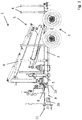
- Forest trailer 1 shown consists essentially of a vehicle frame 2 with a chassis 3, a loading space 5 delimited by a plurality of stanchions 4. Furthermore, a loading crane 6 is mounted at the front end of the vehicle frame 2 and can be actuated hydraulically. To support the forest trailer in the non-attached state or also when the loading crane is in operation, supports 7 are provided which can preferably also be operated hydraulically. At the front end of the vehicle frame a steering drawbar 9 is pivoted about a pivot bearing 8. The pivot bearing 8 has an axis of rotation 10 aligned about a vertical axis (vertical axis). In order to pivot the steering drawbar 9 about the axis of rotation 10 relative to the vehicle frame 2, at least one hydraulically actuable cylinder is provided, which is not shown here, however.
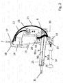
- FIG. 2 shows a first embodiment of a steering drawbar 90 which extends from a trailer coupling 11 to the pivot bearing 8.
- a hydraulic pump 12 is arranged on the underside 90.b of the steering drawbar 90 and is protected by a surrounding housing 13.
- the hydraulic pump 12 is connected to an articulated shaft 14 which can be coupled to a towing vehicle, in particular via its PTO shaft.
- a hydraulic tank 15 is mounted on the upper side 90a of the steering drawbar 90, on which in turn a control block 16 is fastened.
- the control block 16 provides operating levers 17 with which the loading crane 6 and possibly also the supports 7 can be controlled.
- the control block 16 and the hydraulic tank 15 are also protected by a protective rod 18 from external influences, such as falling branches or the like.
- the hydraulic circuit is shown in the schematic representation Fig. 5 evident.
- the hydraulic pump 12 is connected to the oil tank 15 via a suction line 19 and a suction filter 20 and to the control block 16 via a pressure line 21.
- the control block 16 is in turn connected to the hydraulic tank via a return line 22 and a return filter 23.
- hydraulic lines 24, 25 are provided between the control block 16 and the hydraulically operated unit.
- the hydraulic tank 15 with the control block 16 arranged thereon is arranged on the upper side 90a of the steering drawbar 90 at the end having the pivot bearing 8.
- the front region that is to say the region which faces the trailer coupling 11, can therefore have a platform 25 on the upper side 90a of the steering drawbar 90 for an operator to stand.
- a seat for sitting an operator can also be provided in this area.
- a step opening 26 is provided in a side wall of the steering drawbar 19.
- the trailer coupling 11 is in the illustrated embodiment of the Fig. 2 formed as a towing eye, but can also be formed by any other suitable coupling, such as a ball mouth.
- any other suitable coupling such as a ball mouth.
- Figure 1 Both variants are shown, although in practice only one of the two coupling options will be installed.
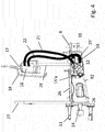
- Steering drawbar 91 shown differs from the exemplary embodiment according to Figure 2 only in that the hydraulic pump 12 is arranged inside the steering drawbar 91. Otherwise, the arrangement of the hydraulic tank 15 and the control block corresponds to the previous embodiment.
- the arrangement of the hydraulic pump 12 in the interior of the steering drawbar 91 means that the propeller shaft 14 projects into the steering drawbar 91 via an opening 90c in the region of the end face and is coupled there to the hydraulic pump.
- the trailer coupling 11 can be attached to the steering drawbar 91 either above or below the propeller shaft 4.
- a design of the drawbar with a connecting plate and a coupling element is particularly suitable for this, as is the case, for example, in the earlier patent application DE 10 2017 126 711 A1 is described in more detail.
- Figure 3 Both a drawbar eye arranged above the articulated shaft 14 and a jaw coupling arranged below the articulated shaft 14 are shown, wherein in practical use only one of the two coupling options will expediently be mounted. So that the operator standing on the platform 25 does not accidentally fall backwards into the area between the towing vehicle and the forest trailer, a support frame 27 can be provided at the front end of the steering drawbar 91.
- FIG 4 shows a further embodiment of a steering drawbar 92, in which the hydraulic pump 12 is arranged inside the steering drawbar 92.
- the hydraulic tank 15 ' is also located here in the interior of the steering drawbar 92.
- the further special feature here is that the hydraulic pump 12 is arranged in the interior of the hydraulic tank 15'.
- the hydraulic pump 12 Expediently arranged on the end face 15'a of the hydraulic tank 15 'facing the front end of the steering drawbar 92, so that the coupling to the propeller shaft 14 can be carried out in a simple manner.
- the suction line 19 can then be made correspondingly short.
- the control block 16 is then mounted on a column 28 so that the operating levers 17 are at a height which is favorable for the operator.
- the hydraulic pump 12, the control block 16 and the hydraulic tank 15, 15 ' are located on or in the steering drawbar.
- these components are arranged in a stationary manner relative to one another even when the steering drawbar 90, 91, 92 turns around the axis of rotation 10.
- the suction line 19, the pressure line 21 and the return line 22 are therefore not subjected to any movements due to a possible steering lock of the steering drawbar and are therefore less susceptible to any damage.
- the interval for exchanging these lines can also be extended accordingly.
- hydraulic lines can still be used flexibly for these lines, one or the other line could also be designed as a rigid pipeline.
Landscapes
- Engineering & Computer Science (AREA)
- Life Sciences & Earth Sciences (AREA)
- Chemical & Material Sciences (AREA)
- Combustion & Propulsion (AREA)
- Transportation (AREA)
- Mechanical Engineering (AREA)
- Biodiversity & Conservation Biology (AREA)
- Ecology (AREA)
- Forests & Forestry (AREA)
- Environmental Sciences (AREA)
- Steering-Linkage Mechanisms And Four-Wheel Steering (AREA)
- Power Steering Mechanism (AREA)
Abstract
Description
- Die Erfindung betrifft einen Forstanhänger mit einer sich von einer Anhängerkupplung bis zu einem Drehlager erstreckenden Lenkdeichsel sowie einer über eine Gelenkwelle mit einem Zugfahrzeug koppelbaren Hydraulikpumpe.
- Weiterhin ist ein Steuerblock zur Steuerung wenigstens eines hydraulisch betriebenen Aggregats und ein mit der Hydraulikpumpe und dem Steuerblock in Verbindung stehendender Hydrauliktank vorgesehen. Ein solcher Forstanhänger kann beispielsweise als sogenannter Rückeanhänger ausgebildet sein, der einen Ladekran umfasst, mit den Baumstämme und Äste in einem Ladebereich des Rückeanhängers abgelegt werden können.
- Aus der
DE 10 2009 029 037 B4 ist ein Forstanhänger mit einer Lenkdeichsel bekannt, wobei die Hydraulikpumpe in einem hohl ausgebildeten Abschnitt der Lenkdeichsel angeordnet ist. Durch diese Anordnung der Hydraulikpumpe ist diese vor Beschädigungen durch Unterlenker, Oberlenker und durch herabfallendes Geäst geschützt. Ein weiterer Vorteil besteht auch darin, dass die an die Hydraulikpumpe angeschlossenen Saug- bzw. Druckleitungen geschützt innerhalb der Deichsel geführt werden können. - Der Erfindung liegt nun die Aufgabe zugrunde, die Betriebssicherheit weiter zu verbessern, um den Bediener vor Leckagen zu schützen. So stellt austretendes Öl, insbesondere aus unter Druck stehenden Hydraulikleitungen eine ernsthafte gesundheitliche Gefahr für den Bediener dar. Die Hydraulikleitungen werden daher üblicherweise zusätzlich mit einer Schutzummantelung versehen.
- Erfindungsgemäß wird die Aufgabe durch einen Forstanhänger gemäß den Merkmalen des Anspruches 1 gelöst, wobei die Hydraulikpumpe, der Steuerblock und der Hydrauliktank an oder in der Lenkdeichsel angeordnet sind.
- Bisher wurde der Hydrauliktank bei Forstanhängern immer im Bereich des eigentlichen Anhängers, d. h. in Fahrtrichtung hinter dem Drehlager der Lenkdeichsel angeordnet. Dies hat aber den entscheidenden Nachteil, dass die Hydraulikleitungen zwischen dem Hydrauliktank und der Hydraulikpumpe sowie dem Steuerblock bei einem Lenkeinschlag der Lenkdeichsel beansprucht werden, um die Relativbewegung zwischen Hydrauliktank, Hydraulikpumpe und Steuerblock auszugleichen. Jede Relativbewegung wirkt sich jedoch negativ auf die Lebensdauer der Hydraulikschläuche aus. Außerdem stellt jede Relativbewegung eine potenzielle Gefahr für eine Beschädigung dar. Um eine Leckage zu vermeiden, sind daher derartige Hydraulikschläuche in bestimmten Zeitintervallen auszutauschen, was mit zusätzlichen Kosten verbunden ist.
- Es ist natürlich auch bekannt, dass man die Pumpe und den Hydrauliktank im Bereich des Anhängers anordnet, jedoch gestaltet sich dann der Antriebstrang vom Zugfahrzeug zur Hydraulikpumpe als wesentlich aufwendiger, da dieser mehrgelenkig ausgebildet werden muss, um die Lenkbeweglichkeit der Lenkdeichsel ausgleichen zu können. Bei der erfindungsgemäßen Anordnung, wonach die Hydraulikpumpe, der Steuerblock und der Hydrauliktank an oder in der Lenkdeichsel angeordnet sind, bleiben diese auch bei einem Lenkeinschlag der Lenkdeichsel um das Drehlager relativ zueinander ortsfest ausgerichtet. Dies gilt dann natürlich auch für die Hydraulikleitungen zwischen diesen Bauteilen, wobei insbesondere die Verbindung zwischen der Hydraulikpumpe und dem Steuerblock durch eine Druckleitung und die Verbindung zwischen dem Hydrauliktank und der Hydraulikpumpe durch eine Saugleitung ausgebildet werden kann.
- Im Rahmen der Erfindung kann die Hydraulikpumpe auf einer Unterseite, einer Oberseite oder im Inneren der Lenkdeichsel angeordnet werden. Bei einer Anordnung auf der Unter- oder Oberseite der Lenkdeichsel wird die Hydraulikpumpe zweckmäßigerweise durch ein Gehäuse (Umhausung) vor äußeren Einflüssen geschützt. Den besten Schutz und die kompakteste Anordnung bietet jedoch eine Platzierung der Hydraulikpumpe im Inneren der Lenkdeichsel. Gemäß einer bevorzugten Ausgestaltung der Erfindung wird der Hydrauliktank auf der Oberseite der Lenkdeichsel angeordnet und gemäß einer weiteren Ausgestaltung kann dann auch der Steuerblock auf dem Hydrauliktank befestigt werden. Die mit dem Hydrauliktank und dem Steuerblock in Verbindung stehende Hydraulikpumpe wird dann wahlweise auf der Unterseite der Lenkdeichsel oder im Inneren der Lenkdeichsel angeordnet.
- Gemäß einer weiteren Ausgestaltung der Erfindung ist auf der Oberseite der Lenkdeichsel eine Plattform zum Stehen oder ein Sitz zum Sitzen einer Bedienperson zur Betätigung des Steuerblocks vorgesehen. Bei einer Anordnung der Steuerblocks auf dem Hydrauliktank befindet sich dieser für die Bedienperson auch gleich in der richtigen Höhe. Wird zudem die Plattform bzw. der Sitz an dem die Anhängerkupplung aufweisenden Ende der Lenkdeichsel und der Steuerblock an dem das Drehlager aufweisenden Ende der Lenkdeichsel angeordnet, ist die Bedienperson bei der Betätigung des Steuerblocks zum Anhänger hin ausgerichtet und hat somit einen guten Überblick über den Ladebereich und den Wirkbereich des Ladekrans. Um das Betreten der Plattform auf der Oberseite der Lenkdeichsel zu erleichtern kann an der Lenkdeichsel eine Trittstufe, beispielsweise in Form einer in eine Seitenwandung der Lenkdeichsel ausgebildeten Trittöffnung vorgesehen werden.
- Das wenigstens eine hydraulisch betriebene Aggregat kann beispielsweise durch einen Forstkran und/oder Stützen zum Abstützen des Forstanhängers ausgebildet werden.
- Gemäß einem weiteren Ausführungsbeispiel der Erfindung besteht auch die Möglichkeit, den Hydrauliktank im Inneren der Lenkdeichsel anzuordnen, da diese üblicherweise hohl ausgebildet ist und hierfür genügend Platz bieten würde. Bei einer Anordnung des Hydrauliktanks im Inneren der Lenkdeichsel würde es sich dann ggf. auch anbieten, die Hydraulikpumpe im Inneren der Lenkdeichsel und insbesondere im Inneren des Hydrauliktanks vorzusehen. Dadurch würde sich eine besonders platzsparende Anordnung ergeben. Die Gelenkwelle, mit der die Hydraulikpumpe mit der Zapfwelle eines Zugfahrzeugs verbunden wird, kann je nach Anordnung der Hydraulikpumpe oberhalb oder unterhalb der Anhängerkupplung verlaufen. Wird die Hydraulikpumpe im Inneren der Lenkdeichsel oder an der Unterseite der Lenkdeichsel angeordnet, würde die Gelenkwelle zweckmäßigerweise unterhalb der Anhängerkupplung verlaufen. Bei einer Anordnung der Hydraulikpumpe im Inneren der Lenkdeichsel käme aber auch ein Verlauf der Gelenkwelle oberhalb der Anhängerkupplung in Betracht. Diese Ausführung bietet sich natürlich insbesondere auch dann an, wenn die Hydraulikpumpe auf der Oberseite der Lenkdeichsel platziert wird.
- Weitere Ausgestaltungen der Erfindung werden im Folgenden anhand der Beschreibung einiger Ausführungsbeispiele und der Zeichnung näher erläutert.
- In der Zeichnung zeigen
- Fig. 1
- eine schematische Seitenansicht eines Forstanhängers,
- Fig. 2
- eine schematische Seitenansicht der Lenkdeichsel gemäß einem ersten Ausführungsbeispiel,
- Fig. 3
- eine schematische Seitenansicht der Lenkdeichsel gemäß einem zweiten Ausführungsbeispiel,
- Fig. 4
- eine schematische Seitenansicht der Lenkdeichsel gemäß einem dritten Ausführungsbeispiel und
- Fig. 5
- eine schematische Darstellung des Hydraulikkreislaufs.
- Der in
Figur 1 dargestellte Forstanhänger 1 besteht im Wesentlichen aus einem Fahrzeugrahmen 2 mit einem Fahrwerk 3, einem durch mehrere Rungen 4 begrenzten Laderaum 5. Ferner ist am vorderen Ende des Fahrzeugrahmens 2 ein Ladekran 6 montiert, der hydraulisch betätigbar ist. Zum Abstützen des Forstanhängers im nichtangehängten Zustand oder auch beim Betrieb des Ladekrans sind Stützen 7 vorgesehen, die vorzugsweise auch hydraulisch betätigt werden können. Am vorderen Ende des Fahrzeugrahmens ist eine um ein Drehlager 8 schwenkbare Lenkdeichsel 9 angehängt. Das Drehlager 8 weist eine um eine Hochachse (vertikale Achse) ausgerichtete Drehachse 10 auf. Um die Lenkdeichsel 9 um die Drehachse 10 relativ zum Fahrzeugrahmen 2 zu verschwenken, ist wenigstens ein hydraulisch betätigbarer Zylinder vorgesehen, der hier jedoch nicht näher dargestellt ist. - Anhand der
Figuren 2 bis 4 werden im Folgenden drei verschiedene Ausgestaltungen (90, 91, 92) der Lenkdeichsel beschrieben. -
Figur 2 zeigt ein erstes Ausführungsbeispiel einer Lenkdeichsel 90, die sich von einer Anhängerkupplung 11 bis zum Drehlager 8 erstreckt. Auf der Unterseite 90.b der Lenkdeichsel 90 ist eine Hydraulikpumpe 12 angeordnet, die durch ein umgebendes Gehäuse 13 geschützt ist. Die Hydraulikpumpe 12 steht mit einer Gelenkwelle 14 in Verbindung, die mit einem Zugfahrzeug, insbesondere über dessen Zapfwelle, koppelbar ist. Auf der Oberseite 90a der Lenkdeichsel 90 ist ein Hydrauliktank 15 montiert, auf dem wiederum ein Steuerblock 16 befestigt ist. Der Steuerblock 16 sieht Bedienhebel 17 vor, mit denen sich der Ladekran 6 und ggf. auch die Stützen 7 steuern lassen. Der Steuerblock 16 und der Hydrauliktank 15 sind zudem über ein Schutzgestänge 18 vor äußeren Einwirkungen, wie herabfallenden Ästen oder dergleichen, geschützt. - Der Hydraulikkreislauf ist aus der schematischen Darstellung gemäß
Fig. 5 ersichtlich. Dabei steht die Hydraulikpumpe 12 über eine Saugleitung 19 und einen Saugfilter 20 mit dem Öltank 15 und über eine Druckleitung 21 mit dem Steuerblock 16 in Verbindung. Der Steuerblock 16 ist wiederum über eine Rücklaufleitung 22 und einen Rücklauffilter 23 mit dem Hydrauliktank verbunden. Zur Steuerung des hydraulisch betriebenen Aggregats (Ladekran 6) sind zwischen Steuerblock 16 und dem hydraulisch betriebenen Aggregat Hydraulikleitungen 24, 25 vorgesehen. - Der Hydrauliktank 15 mit dem darauf angeordneten Steuerblock 16 ist auf der Oberseite 90a der Lenkdeichsel 90 an dem das Drehlager 8 aufweisenden Ende angeordnet. Der vordere Bereich, also der Bereich, welcher der Anhängerkupplung 11 zugewandt ist, kann daher auf der Oberseite 90a der Lenkdeichsel 90 eine Plattform 25 zum Stehen einer Bedienperson aufweisen. Alternativ kann in diesem Bereich aber auch ein Sitz zum Sitzen einer Bedienperson vorgesehen werden. Um das Besteigen der Plattform zu erleichtern, ist in einer Seitenwandung der Lenkdeichsel 19 eine Trittöffnung 26 vorgesehen.
- Die Anhängerkupplung 11 ist im dargestellten Ausführungsbeispiel der
Fig. 2 als Zugöse ausgebildet, kann aber auch durch jede andere geeignete Kupplung, wie beispielsweise ein Kugelmaul, ausgebildet werden. InFigur 1 sind beide Varianten dargestellt, wenngleich in der Praxis nur eine der beiden Kupplungsmöglichkeiten montiert sein wird. - Die in
Figur 3 dargestellte Lenkdeichsel 91 unterscheidet sich vom Ausführungsbeispiel gemäßFigur 2 lediglich dadurch, dass die Hydraulikpumpe 12 im Inneren der Lenkdeichsel 91 angeordnet ist. Ansonsten stimmt die Anordnung des Hydrauliktanks 15 und des Steuerblocks mit dem vorhergehenden Ausführungsbeispiel überein. Die Anordnung der Hydraulikpumpe 12 im Inneren der Lenkdeichsel 91 bedingt, dass die Gelenkwelle 14 über eine Öffnung 90c im Bereich der Stirnseite in die Lenkdeichsel 91 hineinragt und dort mit der Hydraulikpumpe gekoppelt ist. - Bei dieser Ausführung kann die Anhängerkupplung 11 wahlweise oberhalb oder unterhalb der Gelenkwelle 4 an der Lenkdeichsel 91 befestigt werden. Hierfür bietet sich insbesondere eine Ausgestaltung der Zugdeichsel mit einer Anschlussplatte und einem Kupplungselement an, wie dies beispielsweise in der älteren Patentanmeldung
DE 10 2017 126 711 A1 näher beschrieben ist. InFigur 3 ist sowohl eine oberhalb der Gelenkwelle 14 angeordnete Zugöse als auch eine unterhalb der Gelenkwelle 14 angeordnete Maulkupplung dargestellt, wobei im praktischen Gebrauch zweckmäßigerweise nur eine der beiden Kupplungsmöglichkeiten montiert sein wird. Damit die auf der Plattform 25 stehende Bedienperson nicht versehentlich rückwärts in den Bereich zwischen Zugfahrzeug und Forstanhänger fällt, kann am vorderen Ende der Lenkdeichsel 91 ein Abstützrahmen 27 vorgesehen werden. -
Figur 4 zeigt ein weiteres Ausführungsbeispiel einer Lenkdeichsel 92, bei der die Hydraulikpumpe 12 im Inneren der Lenkdeichsel 92 angeordnet ist. Hier befindet sich zudem auch der Hydrauliktank 15' im Inneren der Lenkdeichsel 92. Die weitere Besonderheit besteht dabei darin, dass die Hydraulikpumpe 12 im Inneren des Hydrauliktanks 15' angeordnet ist. Hierzu wird die Hydraulikpumpe 12 zweckmäßigerweise an der dem vorderen Ende der Lenkdeichsel 92 zugewandten Stirnfläche 15'a des Hydrauliktanks 15' angeordnet, damit die Ankopplung an die Gelenkwelle 14 auf einfache Weise erfolgen kann. Die Saugleitung 19 kann dann entsprechend kurz ausgebildet werden. Der Steuerblock 16 wird dann auf einer Säule 28 montiert, damit sich die Bedienhebel 17 in einer für die Bedienperson günstigen Höhe befinden. - Bei allen drei Ausführungsbeispielen befinden sich die Hydraulikpumpe 12, der Steuerblock 16 und der Hydrauliktank 15, 15' an oder in der Lenkdeichsel. Dadurch sind diese Bauteile auch bei einem Lenkeinschlag der Lenkdeichsel 90, 91, 92 um die Drehachse 10 relativ zueinander ortsfest angeordnet. Die Saugleitung 19, die Druckleitung 21 und die Rücklaufleitung 22 sind somit keinen Bewegungen durch einen etwaigen Lenkeinschlag der Lenkdeichsel ausgesetzt und sind daher bezüglich etwaiger Beschädigungen weniger anfällig. Dadurch kann auch das Intervall für den Austausch dieser Leitungen entsprechend verlängert werden. Wenngleich für diese Leitungen weiterhin flexibel Hydraulikleitungen eingesetzt werden können, könnte auch die ein oder andere Leitung als starre Rohrleitung ausgeführt werden.
Claims (13)
- Forstanhänger (1) mit- einer sich von einer Anhängerkupplung (11) bis zu einem Drehlager (8) erstreckenden Lenkdeichsel (9),- einer über eine Gelenkwelle (14) mit einem Zugfahrzeug koppelbaren Hydraulikpumpe (12),- einem Steuerblock (16) zur Steuerung wenigstens eines hydraulisch betriebenen Aggregats und- einem mit der Hydraulikpumpe (12) und dem Steuerblock (16) in Verbindung stehenden Hydrauliktank (15, 15'),dadurch gekennzeichnet, dass
die Hydraulikpumpe (12), der Steuerblock (16) und der Hydrauliktank (15, 15') an oder in der Lenkdeichsel (9) angeordnet sind. - Forstanhänger (1) nach Anspruch 1, dadurch gekennzeichnet, dass die Hydraulikpumpe (12), der Steuerblock (16) und der Hydrauliktank (15, 15') auch bei einem Lenkeinschlag der Lenkdeichsel (9) um das Drehlager (8) relativ zueinander ortsfest angeordnet sind.
- Forstanhänger (1) nach Anspruch 1, dadurch gekennzeichnet, dass die Verbindung zwischen der Hydraulikpumpe (12) und dem Steuerblock (16) durch eine Druckleitung (21) und die Verbindung zwischen dem Hydrauliktank (15, 15') und der Hydraulikpumpe (12) durch eine Saugleitung (19) gebildet wird.
- Forstanhänger (1) nach Anspruch 1, dadurch gekennzeichnet, dass der Hydrauliktank (15) auf einer Oberseite der Lenkdeichsel (90, 91) angeordnet ist.
- Forstanhänger (1) nach Anspruch 4, dadurch gekennzeichnet, dass der Steuerblock (16) auf dem Hydrauliktank (15) befestigt ist.
- Forstanhänger (1) nach Anspruch 1, dadurch gekennzeichnet, dass auf einer Oberseite der Lenkdeichsel (9) eine Plattform (25) zum Stehen oder ein Sitz zum Sitzen einer Bedienperson zur Betätigung des Steuerblocks (16) vorgesehen ist.
- Forstanhänger (1) nach Anspruch 6, dadurch gekennzeichnet, dass die Lenkdeichsel (9) wenigstens eine Seitenwandung aufweist, die eine Trittöffnung (26) zum Besteigen der Plattform (25) aufweist.
- Forstanhänger (1) nach Anspruch 6, dadurch gekennzeichnet, dass die Plattform (25) an einem die Anhängerkupplung (11) aufweisenden Ende der Lenkdeichsel (9) und der Steuerblock (16) an einem das Drehlager (8) aufweisenden Ende der Lenkdeichsel (9) angeordnet sind.
- Forstanhänger (1) nach Anspruch 1, dadurch gekennzeichnet, dass die Hydraulikpumpe (12) auf einer Unterseite, einer Oberseite oder im Innern der Lenkdeichsel (9) angeordnet ist.
- Forstanhänger (1) nach Anspruch 1, dadurch gekennzeichnet, dass der Hydrauliktank (15') im Inneren der Lenkdeichsel (92) angeordnet ist.
- Forstanhänger (1) nach Anspruch 1, dadurch gekennzeichnet, dass im Inneren der Lenkdeichsel (92) wenigstens ein Hohlraum angeordnet ist, der den Hydrauliktank (15') bildet und die Hydraulikpumpe (12) im Inneren des Hohlraums angeordnet ist.
- Forstanhänger (1) nach Anspruch 1, dadurch gekennzeichnet, dass das wenigstens eine hydraulisch betriebene Aggregat durch einen Forstkran (6) und/oder Stützen (7) zum Abstützen des Forstanhängers (1) gebildet wird.
- Forstanhänger (1) nach Anspruch 1, dadurch gekennzeichnet, dass das die Gelenkwelle (14) oberhalb oder unterhalb der Anhängerkupplung (11) angeordnet ist.
Applications Claiming Priority (1)
| Application Number | Priority Date | Filing Date | Title |
|---|---|---|---|
| DE102018125725.2A DE102018125725B3 (de) | 2018-10-17 | 2018-10-17 | Forstanhänger |
Publications (2)
| Publication Number | Publication Date |
|---|---|
| EP3639652A1 true EP3639652A1 (de) | 2020-04-22 |
| EP3639652B1 EP3639652B1 (de) | 2021-09-15 |
Family
ID=67224581
Family Applications (1)
| Application Number | Title | Priority Date | Filing Date |
|---|---|---|---|
| EP19190199.0A Active EP3639652B1 (de) | 2018-10-17 | 2019-08-06 | Forstanhänger |
Country Status (2)
| Country | Link |
|---|---|
| EP (1) | EP3639652B1 (de) |
| DE (1) | DE102018125725B3 (de) |
Citations (7)
| Publication number | Priority date | Publication date | Assignee | Title |
|---|---|---|---|---|
| US2896734A (en) * | 1957-09-27 | 1959-07-28 | Allis Chalmers Mfg Co | Hydraulic steering system for jointed vehicles |
| WO1986004310A1 (en) * | 1985-01-17 | 1986-07-31 | Peritate Limited | Slave unit |
| JPH0748815A (ja) * | 1993-08-05 | 1995-02-21 | Mitsubishi Heavy Ind Ltd | ゲレンデ整地装置の整地車両追従制御装置 |
| DE202007006610U1 (de) * | 2007-05-09 | 2007-07-12 | B. Strautmann & Söhne GmbH u. Co. KG | Hydraulische Fahrwerksfederung an Ladewagen |
| DE102009029037B4 (de) | 2008-09-01 | 2013-08-01 | Steindl Krantechnik Ges.M.B.H. | Forstanhänger mit Knickdeichsel |
| EP3332995A1 (de) * | 2016-12-09 | 2018-06-13 | MÜNZ-Fahrzeugbau GmbH & Co. KG | Zugdeichsel für einen fahrzeuganhänger |
| DE102017126711A1 (de) | 2017-11-14 | 2019-05-16 | Infitec Gmbh | Optischer Filter |
Family Cites Families (3)
| Publication number | Priority date | Publication date | Assignee | Title |
|---|---|---|---|---|
| DE3739561A1 (de) * | 1987-11-22 | 1989-06-01 | Albert Hufgard | Anhaengerfahrzeug |
| DE202017001959U1 (de) * | 2017-04-12 | 2017-04-25 | Roland Wittmann | Zugvorrichtung |
| DE202017106581U1 (de) * | 2017-10-30 | 2017-11-17 | Pfanzelt Maschinenbau Gmbh | Fahrzeug |
-
2018
- 2018-10-17 DE DE102018125725.2A patent/DE102018125725B3/de active Active
-
2019
- 2019-08-06 EP EP19190199.0A patent/EP3639652B1/de active Active
Patent Citations (7)
| Publication number | Priority date | Publication date | Assignee | Title |
|---|---|---|---|---|
| US2896734A (en) * | 1957-09-27 | 1959-07-28 | Allis Chalmers Mfg Co | Hydraulic steering system for jointed vehicles |
| WO1986004310A1 (en) * | 1985-01-17 | 1986-07-31 | Peritate Limited | Slave unit |
| JPH0748815A (ja) * | 1993-08-05 | 1995-02-21 | Mitsubishi Heavy Ind Ltd | ゲレンデ整地装置の整地車両追従制御装置 |
| DE202007006610U1 (de) * | 2007-05-09 | 2007-07-12 | B. Strautmann & Söhne GmbH u. Co. KG | Hydraulische Fahrwerksfederung an Ladewagen |
| DE102009029037B4 (de) | 2008-09-01 | 2013-08-01 | Steindl Krantechnik Ges.M.B.H. | Forstanhänger mit Knickdeichsel |
| EP3332995A1 (de) * | 2016-12-09 | 2018-06-13 | MÜNZ-Fahrzeugbau GmbH & Co. KG | Zugdeichsel für einen fahrzeuganhänger |
| DE102017126711A1 (de) | 2017-11-14 | 2019-05-16 | Infitec Gmbh | Optischer Filter |
Also Published As
| Publication number | Publication date |
|---|---|
| EP3639652B1 (de) | 2021-09-15 |
| DE102018125725B3 (de) | 2019-08-01 |
Similar Documents
| Publication | Publication Date | Title |
|---|---|---|
| EP1851159B1 (de) | Stützausleger für fahrbare arbeitsmaschinen | |
| DE1178723B (de) | Lenkvorrichtung fuer Flurfoerderfahrzeuge | |
| EP2199247A2 (de) | Drehverbindung | |
| DE60017964T2 (de) | Mähmaschine | |
| DE2242109C3 (de) | Lastkraftwagen mit kippbarem Führerhaus, sowie Bedienungsvorrichtung dazu | |
| DE202012102356U1 (de) | Anhängerfahrzeug mit Knickdeichsel | |
| DE102017122343A1 (de) | Bogenabstützung mit Klappteil | |
| DE102015005924A1 (de) | Hubwagen und Vorrichtung zum Transport von Lasten | |
| EP3639652B1 (de) | Forstanhänger | |
| DE2705979A1 (de) | Vorrichtung an einem langen schleppoder anhaengerwagen | |
| DE1260734B (de) | Fahrzeugkran | |
| DE10031024B4 (de) | Kombinationstransportzug zum Transport von Lang- oder Kurzmaterial | |
| DE2733994A1 (de) | Abstuetzung fuer ein kran-fahrgestell | |
| DE1075441B (de) | Sattelschlepperanhänger mit selbsttätiger Kupplungsvorrichtung | |
| DE202014001054U1 (de) | Spritzgerät für ein landwirtschaftliches Kraftfahrzeug | |
| AT520604B1 (de) | Zugdeichsel für Anhänger | |
| DE2649962A1 (de) | Sicherheitslenksaeule | |
| DE19604452B4 (de) | Befestigung für den Anbaurahmen eines Frontladers an einem Trägerfahrzeug | |
| DE3119946A1 (de) | Mobile brecheranlage | |
| DE4032399A1 (de) | Verfahren zum manipulieren eines tankbehaelters von einem kraftfahrzeug beim absatteln und aufsatteln des tankbehaelters und fuer die durchfuehrung des verfahrens eingerichtetes kraftfahrzeug | |
| DE3401705A1 (de) | Zugeinrichtung fuer lkw-anhaengerfahrzeuge | |
| DE2606705A1 (de) | Anordnung des lenkzylinders einer hydrostatischen lenkvorrichtung fuer die gelenkten raeder bei einem landwirtschaftlich nutzbaren fahrzeug, z.b. einem schlepper | |
| DE102009029037A1 (de) | Forstanhänger mit Knickdeichsel | |
| DE202012102970U1 (de) | Forstfahrzeug | |
| DE1756407A1 (de) | Stabilisierungseinrichtung fuer Kraftfahrzeuge mit Verladeapparat |
Legal Events
| Date | Code | Title | Description |
|---|---|---|---|
| PUAI | Public reference made under article 153(3) epc to a published international application that has entered the european phase |
Free format text: ORIGINAL CODE: 0009012 |
|
| STAA | Information on the status of an ep patent application or granted ep patent |
Free format text: STATUS: THE APPLICATION HAS BEEN PUBLISHED |
|
| AK | Designated contracting states |
Kind code of ref document: A1 Designated state(s): AL AT BE BG CH CY CZ DE DK EE ES FI FR GB GR HR HU IE IS IT LI LT LU LV MC MK MT NL NO PL PT RO RS SE SI SK SM TR |
|
| AX | Request for extension of the european patent |
Extension state: BA ME |
|
| STAA | Information on the status of an ep patent application or granted ep patent |
Free format text: STATUS: REQUEST FOR EXAMINATION WAS MADE |
|
| 17P | Request for examination filed |
Effective date: 20201012 |
|
| RBV | Designated contracting states (corrected) |
Designated state(s): AL AT BE BG CH CY CZ DE DK EE ES FI FR GB GR HR HU IE IS IT LI LT LU LV MC MK MT NL NO PL PT RO RS SE SI SK SM TR |
|
| GRAP | Despatch of communication of intention to grant a patent |
Free format text: ORIGINAL CODE: EPIDOSNIGR1 |
|
| STAA | Information on the status of an ep patent application or granted ep patent |
Free format text: STATUS: GRANT OF PATENT IS INTENDED |
|
| RIC1 | Information provided on ipc code assigned before grant |
Ipc: B60K 25/06 20060101ALI20210412BHEP Ipc: B60K 17/28 20060101ALI20210412BHEP Ipc: B62D 63/08 20060101ALI20210412BHEP Ipc: A01G 23/00 20060101AFI20210412BHEP |
|
| INTG | Intention to grant announced |
Effective date: 20210506 |
|
| GRAS | Grant fee paid |
Free format text: ORIGINAL CODE: EPIDOSNIGR3 |
|
| GRAA | (expected) grant |
Free format text: ORIGINAL CODE: 0009210 |
|
| STAA | Information on the status of an ep patent application or granted ep patent |
Free format text: STATUS: THE PATENT HAS BEEN GRANTED |
|
| AK | Designated contracting states |
Kind code of ref document: B1 Designated state(s): AL AT BE BG CH CY CZ DE DK EE ES FI FR GB GR HR HU IE IS IT LI LT LU LV MC MK MT NL NO PL PT RO RS SE SI SK SM TR |
|
| REG | Reference to a national code |
Ref country code: CH Ref legal event code: EP |
|
| REG | Reference to a national code |
Ref country code: DE Ref legal event code: R096 Ref document number: 502019002285 Country of ref document: DE |
|
| REG | Reference to a national code |
Ref country code: IE Ref legal event code: FG4D Free format text: LANGUAGE OF EP DOCUMENT: GERMAN |
|
| REG | Reference to a national code |
Ref country code: AT Ref legal event code: REF Ref document number: 1429787 Country of ref document: AT Kind code of ref document: T Effective date: 20211015 |
|
| REG | Reference to a national code |
Ref country code: LT Ref legal event code: MG9D |
|
| REG | Reference to a national code |
Ref country code: NL Ref legal event code: MP Effective date: 20210915 |
|
| PG25 | Lapsed in a contracting state [announced via postgrant information from national office to epo] |
Ref country code: RS Free format text: LAPSE BECAUSE OF FAILURE TO SUBMIT A TRANSLATION OF THE DESCRIPTION OR TO PAY THE FEE WITHIN THE PRESCRIBED TIME-LIMIT Effective date: 20210915 Ref country code: SE Free format text: LAPSE BECAUSE OF FAILURE TO SUBMIT A TRANSLATION OF THE DESCRIPTION OR TO PAY THE FEE WITHIN THE PRESCRIBED TIME-LIMIT Effective date: 20210915 Ref country code: FI Free format text: LAPSE BECAUSE OF FAILURE TO SUBMIT A TRANSLATION OF THE DESCRIPTION OR TO PAY THE FEE WITHIN THE PRESCRIBED TIME-LIMIT Effective date: 20210915 Ref country code: HR Free format text: LAPSE BECAUSE OF FAILURE TO SUBMIT A TRANSLATION OF THE DESCRIPTION OR TO PAY THE FEE WITHIN THE PRESCRIBED TIME-LIMIT Effective date: 20210915 Ref country code: NO Free format text: LAPSE BECAUSE OF FAILURE TO SUBMIT A TRANSLATION OF THE DESCRIPTION OR TO PAY THE FEE WITHIN THE PRESCRIBED TIME-LIMIT Effective date: 20211215 Ref country code: LT Free format text: LAPSE BECAUSE OF FAILURE TO SUBMIT A TRANSLATION OF THE DESCRIPTION OR TO PAY THE FEE WITHIN THE PRESCRIBED TIME-LIMIT Effective date: 20210915 Ref country code: BG Free format text: LAPSE BECAUSE OF FAILURE TO SUBMIT A TRANSLATION OF THE DESCRIPTION OR TO PAY THE FEE WITHIN THE PRESCRIBED TIME-LIMIT Effective date: 20211215 |
|
| PG25 | Lapsed in a contracting state [announced via postgrant information from national office to epo] |
Ref country code: LV Free format text: LAPSE BECAUSE OF FAILURE TO SUBMIT A TRANSLATION OF THE DESCRIPTION OR TO PAY THE FEE WITHIN THE PRESCRIBED TIME-LIMIT Effective date: 20210915 Ref country code: GR Free format text: LAPSE BECAUSE OF FAILURE TO SUBMIT A TRANSLATION OF THE DESCRIPTION OR TO PAY THE FEE WITHIN THE PRESCRIBED TIME-LIMIT Effective date: 20211216 |
|
| PG25 | Lapsed in a contracting state [announced via postgrant information from national office to epo] |
Ref country code: IS Free format text: LAPSE BECAUSE OF FAILURE TO SUBMIT A TRANSLATION OF THE DESCRIPTION OR TO PAY THE FEE WITHIN THE PRESCRIBED TIME-LIMIT Effective date: 20220115 Ref country code: SM Free format text: LAPSE BECAUSE OF FAILURE TO SUBMIT A TRANSLATION OF THE DESCRIPTION OR TO PAY THE FEE WITHIN THE PRESCRIBED TIME-LIMIT Effective date: 20210915 Ref country code: SK Free format text: LAPSE BECAUSE OF FAILURE TO SUBMIT A TRANSLATION OF THE DESCRIPTION OR TO PAY THE FEE WITHIN THE PRESCRIBED TIME-LIMIT Effective date: 20210915 Ref country code: RO Free format text: LAPSE BECAUSE OF FAILURE TO SUBMIT A TRANSLATION OF THE DESCRIPTION OR TO PAY THE FEE WITHIN THE PRESCRIBED TIME-LIMIT Effective date: 20210915 Ref country code: PT Free format text: LAPSE BECAUSE OF FAILURE TO SUBMIT A TRANSLATION OF THE DESCRIPTION OR TO PAY THE FEE WITHIN THE PRESCRIBED TIME-LIMIT Effective date: 20220117 Ref country code: PL Free format text: LAPSE BECAUSE OF FAILURE TO SUBMIT A TRANSLATION OF THE DESCRIPTION OR TO PAY THE FEE WITHIN THE PRESCRIBED TIME-LIMIT Effective date: 20210915 Ref country code: NL Free format text: LAPSE BECAUSE OF FAILURE TO SUBMIT A TRANSLATION OF THE DESCRIPTION OR TO PAY THE FEE WITHIN THE PRESCRIBED TIME-LIMIT Effective date: 20210915 Ref country code: ES Free format text: LAPSE BECAUSE OF FAILURE TO SUBMIT A TRANSLATION OF THE DESCRIPTION OR TO PAY THE FEE WITHIN THE PRESCRIBED TIME-LIMIT Effective date: 20210915 Ref country code: EE Free format text: LAPSE BECAUSE OF FAILURE TO SUBMIT A TRANSLATION OF THE DESCRIPTION OR TO PAY THE FEE WITHIN THE PRESCRIBED TIME-LIMIT Effective date: 20210915 Ref country code: CZ Free format text: LAPSE BECAUSE OF FAILURE TO SUBMIT A TRANSLATION OF THE DESCRIPTION OR TO PAY THE FEE WITHIN THE PRESCRIBED TIME-LIMIT Effective date: 20210915 Ref country code: AL Free format text: LAPSE BECAUSE OF FAILURE TO SUBMIT A TRANSLATION OF THE DESCRIPTION OR TO PAY THE FEE WITHIN THE PRESCRIBED TIME-LIMIT Effective date: 20210915 |
|
| REG | Reference to a national code |
Ref country code: DE Ref legal event code: R097 Ref document number: 502019002285 Country of ref document: DE |
|
| PLBE | No opposition filed within time limit |
Free format text: ORIGINAL CODE: 0009261 |
|
| STAA | Information on the status of an ep patent application or granted ep patent |
Free format text: STATUS: NO OPPOSITION FILED WITHIN TIME LIMIT |
|
| PG25 | Lapsed in a contracting state [announced via postgrant information from national office to epo] |
Ref country code: DK Free format text: LAPSE BECAUSE OF FAILURE TO SUBMIT A TRANSLATION OF THE DESCRIPTION OR TO PAY THE FEE WITHIN THE PRESCRIBED TIME-LIMIT Effective date: 20210915 |
|
| 26N | No opposition filed |
Effective date: 20220616 |
|
| PG25 | Lapsed in a contracting state [announced via postgrant information from national office to epo] |
Ref country code: SI Free format text: LAPSE BECAUSE OF FAILURE TO SUBMIT A TRANSLATION OF THE DESCRIPTION OR TO PAY THE FEE WITHIN THE PRESCRIBED TIME-LIMIT Effective date: 20210915 |
|
| PG25 | Lapsed in a contracting state [announced via postgrant information from national office to epo] |
Ref country code: IT Free format text: LAPSE BECAUSE OF FAILURE TO SUBMIT A TRANSLATION OF THE DESCRIPTION OR TO PAY THE FEE WITHIN THE PRESCRIBED TIME-LIMIT Effective date: 20210915 |
|
| PG25 | Lapsed in a contracting state [announced via postgrant information from national office to epo] |
Ref country code: MC Free format text: LAPSE BECAUSE OF FAILURE TO SUBMIT A TRANSLATION OF THE DESCRIPTION OR TO PAY THE FEE WITHIN THE PRESCRIBED TIME-LIMIT Effective date: 20210915 |
|
| PG25 | Lapsed in a contracting state [announced via postgrant information from national office to epo] |
Ref country code: LU Free format text: LAPSE BECAUSE OF NON-PAYMENT OF DUE FEES Effective date: 20220806 |
|
| REG | Reference to a national code |
Ref country code: BE Ref legal event code: MM Effective date: 20220831 |
|
| PG25 | Lapsed in a contracting state [announced via postgrant information from national office to epo] |
Ref country code: IE Free format text: LAPSE BECAUSE OF NON-PAYMENT OF DUE FEES Effective date: 20220806 |
|
| PG25 | Lapsed in a contracting state [announced via postgrant information from national office to epo] |
Ref country code: BE Free format text: LAPSE BECAUSE OF NON-PAYMENT OF DUE FEES Effective date: 20220831 |
|
| PGFP | Annual fee paid to national office [announced via postgrant information from national office to epo] |
Ref country code: CH Payment date: 20230902 Year of fee payment: 5 |
|
| PGFP | Annual fee paid to national office [announced via postgrant information from national office to epo] |
Ref country code: FR Payment date: 20230828 Year of fee payment: 5 Ref country code: DE Payment date: 20230802 Year of fee payment: 5 |
|
| PG25 | Lapsed in a contracting state [announced via postgrant information from national office to epo] |
Ref country code: HU Free format text: LAPSE BECAUSE OF FAILURE TO SUBMIT A TRANSLATION OF THE DESCRIPTION OR TO PAY THE FEE WITHIN THE PRESCRIBED TIME-LIMIT; INVALID AB INITIO Effective date: 20190806 |
|
| GBPC | Gb: european patent ceased through non-payment of renewal fee |
Effective date: 20230806 |
|
| PG25 | Lapsed in a contracting state [announced via postgrant information from national office to epo] |
Ref country code: CY Free format text: LAPSE BECAUSE OF FAILURE TO SUBMIT A TRANSLATION OF THE DESCRIPTION OR TO PAY THE FEE WITHIN THE PRESCRIBED TIME-LIMIT Effective date: 20210915 |