EP3638599B1 - Verschlussvorrichtung für flüssigkeitsbehälter - Google Patents
Verschlussvorrichtung für flüssigkeitsbehälter Download PDFInfo
- Publication number
- EP3638599B1 EP3638599B1 EP18731360.6A EP18731360A EP3638599B1 EP 3638599 B1 EP3638599 B1 EP 3638599B1 EP 18731360 A EP18731360 A EP 18731360A EP 3638599 B1 EP3638599 B1 EP 3638599B1
- Authority
- EP
- European Patent Office
- Prior art keywords
- membrane
- neck
- base
- tube
- axial
- Prior art date
- Legal status (The legal status is an assumption and is not a legal conclusion. Google has not performed a legal analysis and makes no representation as to the accuracy of the status listed.)
- Active
Links
Images




Classifications
-
- B—PERFORMING OPERATIONS; TRANSPORTING
- B65—CONVEYING; PACKING; STORING; HANDLING THIN OR FILAMENTARY MATERIAL
- B65D—CONTAINERS FOR STORAGE OR TRANSPORT OF ARTICLES OR MATERIALS, e.g. BAGS, BARRELS, BOTTLES, BOXES, CANS, CARTONS, CRATES, DRUMS, JARS, TANKS, HOPPERS, FORWARDING CONTAINERS; ACCESSORIES, CLOSURES, OR FITTINGS THEREFOR; PACKAGING ELEMENTS; PACKAGES
- B65D47/00—Closures with filling and discharging, or with discharging, devices
- B65D47/04—Closures with discharging devices other than pumps
- B65D47/20—Closures with discharging devices other than pumps comprising hand-operated members for controlling discharge
- B65D47/2018—Closures with discharging devices other than pumps comprising hand-operated members for controlling discharge comprising a valve or like element which is opened or closed by deformation of the container or closure
- B65D47/2031—Closures with discharging devices other than pumps comprising hand-operated members for controlling discharge comprising a valve or like element which is opened or closed by deformation of the container or closure the element being formed by a slit, narrow opening or constrictable spout, the size of the outlet passage being able to be varied by increasing or decreasing the pressure
- B65D47/2037—Closures with discharging devices other than pumps comprising hand-operated members for controlling discharge comprising a valve or like element which is opened or closed by deformation of the container or closure the element being formed by a slit, narrow opening or constrictable spout, the size of the outlet passage being able to be varied by increasing or decreasing the pressure the element being opened or closed by actuating a separate element which causes the deformation, e.g. screw cap closing container slit
Definitions
- the present invention relates to a closure device for a liquid container such as a bottle or gourd body.
- the gourds allow the transport of liquids, in particular to take a drink to the place of the practice of a sporting activity or to school. They generally include a container intended to receive the liquid and a removable closure system coupling to the container.
- a closure system comprising a fixed ring intended to be mounted on a bottle body, the ring carrying a shutter extending in a neck which is axially movable.
- the shutter closes the orifice of the neck. Pressing on the neck releases the shutter from the orifice of the neck to access the liquid.
- a seal can be arranged under the shutter to improve the seal in the high closed position.
- a spring is interposed between the neck and the ring to urge the neck in the high closed position.
- This closure system is intuitive and also allows the bottle to be sealed tightly.
- the gap between the shutter and the neck can jam the lips or the tongue of the user, which can interfere with the use of the bottle, in particular by young children.
- this closure system has a relatively large number of parts, which increases its cost and complicates the disassembly and assembly of the system for cleaning.
- US2007181523 describes a known closure system according to the preamble of claim 1 attached.
- One of the aims of the present invention is to provide a closure device for a container exhibiting an actuation which can be easily performed, in particular by young children, exhibiting good sealing quality and comprising a limited number of parts.
- the subject of the invention is a closure device for a liquid container as described in claim 1.
- the membrane can thus be opened by axial thrust from the neck.
- the closure device is easy to operate, so it is easily understood from an early age.
- the membrane allows the closure device to present a good seal.
- the closure device has a limited number of parts. It is completely removable and easy to clean.
- the neck can be mounted to move on the base between a high closing position and a low opening position over an axial stroke allowing that in the low open position, the membrane resiliently urges the neck to return to the high closed position. .
- the neck returns to the high closed position. This allows the gourd to be closed tightly when the gourd is not in use.
- the membrane then plays, on the one hand, the role of a seal and, on the other hand, the role of a return spring in the high closing position of the neck away from the base.
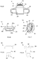
- the figure 1 shows a closure device 1 for a container 2 of liquid, such as a body of a bottle or gourd, for example made of plastic material, allowing in particular the transport of a drink.
- a container 2 of liquid such as a body of a bottle or gourd, for example made of plastic material, allowing in particular the transport of a drink.
- the closure device 1 comprises a base 3 intended to be mounted on the container 2, for example in a removable manner, a neck 4 movably mounted on the base 3 between a high closed position in which the liquid cannot leave the container 2 ( figure 2 ) and a low opening position in which the user can access the liquid ( figure 11 ).
- the base 3 comprises a base 5 and a tube 7.
- the base 3 is preferably made in one piece, for example of plastic material.
- the base 5 has an annular portion, the interior of which carries a fixing means 6, such as a complementary screw thread to the container 2, configured to reversibly secure the base 3 to the container 2 ( figure 2 ).
- the base 5 is closed radially around the tube 7 by a wall 9, for example plane of the base 5 and perpendicular to the axis of the tube 7, the tube 7 projecting from the wall 9 on the side of the neck 4, for example centrally in relation to the plinth 5.
- the base 5 can also carry an articulation member 10 and a locking element 11 intended to cooperate with a cover (not shown) pivotally mounted on the base 3.
- the hollow tube 7 is intended to be placed in communication with the interior of the container 2. At least one orifice 12 is formed in the tube 7, for example at an axial end 13a of the tube 7. The tube 7 thus passes through the base 5 so that once the base 3 is mounted on the container 2 and the neck 4 in the lower open position, the liquid can flow through the tube 7.
- the closure device 1 further comprises an elastic membrane 14 arranged in an opening 15 of the neck 4 ( figures 5 and 6 ).
- the membrane 14 has the general shape of a disc complementary to the circular opening 15 of the neck 4.
- the membrane 14 comprises at least one slit 16 closed on itself in the rest position when the neck 4 is in the upper closed position, thus obstructing the opening 15 of the neck 4 in a sealed manner.
- the membrane 14 is for example a flexible synthetic material such as a silicone material or a thermoplastic elastomer (TPE).
- TPE thermoplastic elastomer
- the membrane 14 is in one piece. It can be obtained by molding.
- the slot 16 is for example formed by a cutout of the membrane 14.
- the membrane 14 and the opening 15 of the neck 4 comprise for example an annular groove 17 able to cooperate with a complementary annular rib 18, one being carried by the membrane 14, the other being carried by the opening 15.
- the annular groove 17 is for example formed in the membrane 14 ( figure 6 ) and the annular rib 18 is formed in the opening 15 of the neck 4 ( figure 5 ) Or vice versa.
- the annular groove 17 and the annular rib 18 allow the tight fitting and maintenance of the membrane 14 in the opening 15 of the neck 4.
- the membrane 14 can be easily disassembled in order to be cleaned and possibly replaced.
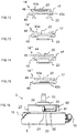
- the tube 7 is arranged at the rear of the membrane 14 in the high closing position of the neck 4 so that the lowering of the neck 4 towards the base 3 in the low opening position in the axial direction of the tube 7, opens the membrane 14 by deformation of the at least one slot 16 by the axial end 13a of the tube 7. More precisely, the axial end 13a of the tube 7 engages through the at least one slot 16 to open the membrane 14 ( figures 10 and 11 ).
- the axial end 13a of the tube 7 thus deforms the elastic membrane 14 to free a passage for the liquid ( figures 2 and 11 ).
- the neck 4 is movably mounted on the base 3 between a high closing position and a low opening position on an axial stroke d allowing for example that in the low opening position, the membrane 14 resiliently urges the return of the neck. 4 in high closed position ( figure 2 ).
- the axial stroke d can be between 4mm and 6mm, such as of the order of 5mm.
- the high position of the neck 4 moves the tube 7 away from the membrane 14 which returns to a rest position, closed on itself. So when the user releases the pressure exerted on the neck 4, the neck 4 returns to the high closed position. This allows the gourd to be closed tightly when the gourd is not in use.
- the membrane 14 then plays, on the one hand, the role of a seal and, on the other hand, a role of a return spring in the high closed position of the neck 4 away from the base 3.
- an additional elastic member 19 such as an elastic blade or a helical spring, interposed between the neck 4 and the base 3 to urge the neck 4 in the high closing position (dotted on the figure). figure 2 ).
- An additional elastic member 19 makes it possible to secure the return to the high closing position independently of any wear of the membrane 14. The closing device 1 is thus urged into the high closing position when no pressure is exerted on the neck. 4, by biasing the membrane 14 and / or by biasing the additional elastic member 19.
- the annular groove 17 can be formed in asymmetric annular beads 45, 46 of the membrane 14, the inner bead 45 (side containing 2) being thicker than the outer bead 46, the inner bead 45 cooperating with a complementary shoulder 47 of the neck. 4 ( figures 5 and 6 ).
- This asymmetry of the membrane 14 allows it to be more difficult to push out from the inside than to push out from the outside of the container 2. The membrane 14 can thus be removed more easily when it is pushed by the. user from outside the neck 4 only when it is pushed by the tube 7.
- the at least one slot 16 is formed in a flat wall 20 of the membrane 14 ( figure 6 ).
- the wall 20 is for example arranged in at least one recess 43a, 43b of the membrane 14, the recess 43a, 43b here forming an annular step in the membrane 14.
- the at least one recess 43b is preferably located on the side of the membrane 14 intended to cooperate with the axial end 13a of the tube 7.
- the wall 20 is arranged in two recesses 43a, 43b of the membrane 14. , formed in the two opposite faces of the membrane 14.
- the at least one recess 43a, 43b creates a zone of rigidity which favors the return of the membrane 14 to the rest position, which improves the quality of the elastic return of the membrane 14 to the high closed position.
- the orifice 12 of the tube 7 located at the axial end 13a of the tube 7 can thus be closed by the membrane 14 in the high position of closing ( figure 2 ).
- the membrane 14 then acts as a front seal, closing the orifice 12 of the tube 7 in a leaktight manner in the high closed position.
- the membrane 14 further comprises here two slots 16 which intersect perpendicularly in a cross ( figure 7 ).
- This cross shape improves the seal between the tube 7 and the membrane 14 in the low opening position and makes it possible to balance the force applied to the neck 4 to deform and open the membrane 14.
- the return force of the membrane 14 towards the high closed position is also optimized.
- the ends 21 of the at least one slot 16 divide into two branches, ending in "Y". This "Y" shape makes it possible to limit tears or cracks in the ends 21 of the slots 16.
- At least a portion of the tube 7 is in a frustoconical shape.
- the tube 7 has for example a two-stage shape, comprising a distal portion 13 surmounting a proximal portion 22, the proximal portion 22 projecting directly from the wall 9 of the base 5, the distal portion 13 having a narrower passage than the proximal portion 22 ( figure 4a ).
- the axial end 13a of the distal portion 13 of the tube 7 allowing the opening of the membrane 14 has a frustoconical shape ( figure 4a ).
- the angle ⁇ 1 between the conical surface of the axial end 13a and the axis of the tube 7 is for example between 1 ° and 25 °.
- the frustoconical shape in which the axial end 13a of the tube 7 is inscribed allows progressive opening of the membrane 14, generating a progressive force to be exerted for the user, which is more ergonomic. In addition, this allows a gradual tensioning of the membrane 14, limiting the wear of the membrane 14. This shape also allows better plating of the lips of the at least one slot 16 against the axial end 13a, allowing '' obtain a very good seal between the membrane 14 and the tube 7.
- the angle ⁇ 2 between the conical surface of the base 13b and a plane perpendicular to the axis of the tube 7 is for example between 90 ° and 115 °.
- the membrane 14 can also include a radial sealing member 23 formed by a ring carrying an annular end lip ( figure 6 ).
- the membrane 14 is in one piece with the radial sealing member 23.
- the annular sealing lip is intended to be in contact with the tube 7 of the base 3 and more precisely, with the base 13b of the distal portion 13 of the tube 7, in particular in the low open position ( figure 11 ).
- the neck 4 and the base 3 further include cooperation means making it possible to maintain and guide the neck 4 relative to the base 3.
- the cooperation means comprise for example at least one axial groove 24 cooperating with at least one complementary lug 25, one being carried by the neck 4, the other being carried by the base 3 ( figures 3 and 5 ).
- the axial groove 24 extends in the axial direction of the tube 7. It has an axial stop 26 against which the lug 25 bears in the high closed position.
- the base 3 is provided with two diametrically opposed axial grooves 24, for example carried by a crown 27 of the base 3, the crown 27 surmounting the base 5 and concentrically surrounding the proximal portion 22 of the tube 7 ( figure 4a ).
- the neck 4 carries for example two lugs 25 extending radially towards one another. The lugs 25 protrude from the end of a skirt 28 of the neck 4 ( figure 5 ).
- the tube 7 of the base 3, and more particularly the proximal portion 22 of the tube 7, to be cylindrical and cooperate with a cylindrical guide 29 complementary to the neck 4 to guide the axial and rotary displacement of the neck 4 with respect to to the base 3.
- the cylindrical guide 29 extends for example from the skirt 28 of the neck 4, inside the skirt 28 and concentrically with respect to the axis of the tube 7.
- the end of the cylindrical guide 29 can form a stop for the neck 4 when the neck 4 is lowered against the wall 9 of the base 5 in the low open position ( figure 11 ), limiting the axial travel d of the neck 4 ( figure 2 ).
- the fact that the end of the cylndrique guide 29 is located inside the neck 4 also makes it possible to avoid pinching the user's fingers in the low open position.
- the cooperation means are also configured to guide the assembly and disassembly of the neck 4 on the base 3.
- the cooperation means comprise at least one mounting groove 30, communicating with the axial groove. 24 and cooperating with the at least one lug 25 ( figure 3 ).
- the mounting groove 30 extends partially around the periphery of the neck 4 or of the base 3, allowing a “push-turned” type mounting, also called a “bayonet” mounting. ”Or“ quarter turn ”assembly.
- the mounting groove 30 extends for example over an angle of between 30 ° (1/12 turn) and 90 ° (quarter turn).
- the base 3 to carry two diametrically opposed mounting grooves 30, carried by the crown 27 of the base 3 ( figures 3 and 4a ).
- the mounting groove 30 is configured to guide a gradual lowering of the neck 4 towards the base 3 simultaneously with the rotation of the neck 4 during the mounting of the neck 4.
- the mounting groove 30 comprises for example an assembly ramp 31, linear ( figure 3 ).
- the mounting groove 30 may further include an annular groove 32, perpendicular to the axial groove 24 and interposed between the axial groove 24 and the mounting ramp 31.
- the annular groove 32 and the axial groove 24 meet perpendicularly to the opposite the axial stop 26.
- the axial groove 24 is for example deeper than the assembly groove 30.
- the at least one lug 25 “falls” into the axial groove 24, which makes it possible to inform the user of the correct assembly. of the neck 4.
- the user presses the neck 4 to deform it and remove the at least one lug 25 from the axial groove 24 and to engage it on the mounting groove 30.
- a security is thus added making it possible to avoid unintentional dismantling of the neck 4 or the dismantling of the neck 4, in particular by a child.
- the mounting groove 30 may further include an indexing clip 33 interposed between the mounting groove 30 and the axial groove 24.
- the indexing clip 33 is formed by an extra thickness. It allows the indexing of the position of the lug 25 in the axial groove 24. When the user feels that he has passed the hard point of the indexing clip 33, he knows that the closure device 1 is assembled correctly and that the gourd can be used.
- a mark 24 can be arranged on the outside of the skirt 28 of the neck 4 to facilitate the identification of the angular position of the neck 4 allowing the insertion of at least one lug 25 in the guide groove 30 ( figure 1 ).
- the user pivots the neck 4 on the base 3 until a mounting position is found for the insertion of at least one lug 25 in the mounting groove 30.
- the latter is gradually inserted into the at least one mounting ramp 31 in order to lower itself to the low opening position and then to be guided in rotation by the at least one annular groove 32.
- the at least one lug 25 enters the at least one axial groove 24.
- the neck 4 "released”, “goes up” to the at least one axial stop 26 ( figure 3 ).
- the user When removing the neck 4, the user begins by lowering the neck 4 to place it in the low open position. Then he presses the neck 4 to come out of the axial groove 24 before turning it. The at least one lug 25 then rises the guide ramp 30 until the neck 4 becomes detached from the base 3.
- the at least one mounting groove 30 mounting and removing the neck 4 in the base 3 is very easy to perform.
- the assembly groove 30 drives the neck 4 directly to the assembled position of use. Turning the neck 4 on the base 3 to position it correctly is also very intuitive. Furthermore, the fact of having to push while turning the neck 4 in order to be able to dismantle it adds security to prevent dismantling by a child.
- the closure device 1 may further include an air inlet membrane 35, arranged in an orifice in the wall 9 of the base 5 of the base 3 ( figure 2 ).
- the air inlet membrane 35 is for example a flexible synthetic material, such as a silicone material or a thermoplastic elastomer (TPE).
- TPE thermoplastic elastomer
- the air inlet membrane 35 is formed by an elastic element having at least one slot 38, closed in the rest state ( figure 8 and 9 ).
- the slot 38 is able to open when the pressure in the container 2 is lower than the external pressure, that is to say the pressure prevailing in the space located between the base 3 and the neck 4, to allow the entry of air into the container 2 when the liquid flows through the tube 7.
- the air inlet membrane 35 comprises a hollow elastic member in one piece having an open end 36 and a concave end 37 in which at least one slit 38 is formed, the slit 38 being closed in the state. rest, closing the concave end 37.
- the concave end 37 extends from the side of the container 2 ( figure 2 ).
- the air inlet membrane 35 may include a retaining bead 39 arranged on the side of the open end 25 and an annular extra thickness 40 making it possible to retain the air inlet membrane 35 in the orifice of the wall 9. ( figures 8 and 9 ).
- the air inlet membrane 35 can also be molded onto the wall 9.
- the neck 4 In use, at rest, the neck 4 is urged in the high closing position by the elasticity of the membrane 14 and possibly by the additional elastic member 19 ( figure 2 ).
- the slots 16 of the membrane 14 are closed on themselves.
- the membrane 14 is then not deformed and closed in a sealed manner.
- the membrane 14 is arranged against the orifice 12 of the tube 7 preventing the flow of liquid out of the tube 7.
- the at least one slot 38 of the air inlet membrane 35 is closed ( figure 2 ).
- the user When the user wishes to drink, he presses for example with his mouth on the neck 4, exerting axial pressure on the neck 4 which translates towards the base 3.
- the proximal cylindrical portion 22 of the tube 7 cooperates with the cylindrical guide 29 complementary to the neck 4 to guide the axial displacement of the neck 4 towards the base 3.
- the lowering of the neck 4 towards the base 3 deforms the at least one slot 16 of the membrane 14 by pushing from the axial end 13a of the tube 7.
- the axial end 13a of the tube 7 engages through the at least a slot 16 to open the membrane 14 ( figure 10 ).
- the frustoconical shape in which the axial end 13a is inscribed allows a progressive deformation and therefore a progressive opening of the membrane 14 ( figure 10 ).
- the slot 38 of the air inlet membrane 35 can open to allow the entry of air into the container 2 when the liquid flows through the tube 7.
- the closure device 1 thus allows the user to access the liquid in the container 2 by simply pressing the mouth on the neck 4.
- the closure device 1 is therefore simple, easy to use and has very little parts: two membranes 14, 35, a base 3, a neck 4 and possibly an additional elastic member 19.
- the membrane 14 indeed plays on the one hand, a role of seal making it possible to obtain a tight closure of the closure device 1 and makes it possible to guarantee the seal around the tube 7 open in the lower open position.
- the membrane 14 acts as a return spring in the high closing position of the neck 4 away from the base 3.
- the limited number of parts lowers the manufacturing cost and facilitates assembly and disassembly. of the closure device 1 by the user for cleaning.
- the closure device 1 is completely removable, which facilitates cleaning and allows, if necessary, easy replacement of the membrane 14.
- the figure 12 shows a second embodiment of a membrane 14 ′.
- This embodiment differs from the previous one by the fact that the at least one slot 16 is formed in a wall 20 'convex of the membrane 14'.
- This curved 20 'wall allows in particular to improve the sealing tightness of the orifice 12 of the tube 7 by the membrane 14 'in the high closed position.
- the figure 13 shows a third embodiment of a membrane 14 "for which the at least one slot 16 is formed in a flat wall 20 of the membrane 14".
- the wall 20 is arranged in a single recess 43a of the membrane 14 "forming an annular step which is not located on the side of the membrane 14" intended to cooperate with the axial end 13a of the tube 7.
- the figure 14 shows a fourth embodiment of a membrane 14 "'.
- This embodiment differs from the third embodiment in that the wall 20 is arranged in a recess 44 at the frustoconical edge of the membrane 14 "'.
- the figure 15 shows a fifth embodiment of a membrane 14 "". This embodiment differs from the first embodiment in that the membrane 14 "" does not include a radial sealing member.
- the figure 16 shows a second embodiment of the mounting groove 30 'of the cooperation means.
- the mounting groove 30 ' has a general “U” shape.
- the mounting groove 30 ' has an axial mounting groove 41 and an annular groove 32', perpendicular to the axial groove 24 and the axial mounting groove 41, the annular groove 32 'being interposed between the axial groove 24 and the groove axial mounting 41.
- the annular groove 32 'and the axial groove 24 meet perpendicularly, opposite the axial stop 26.
- the user pivots the neck 4 on the base 3 until a mounting position is found allowing the lugs 25 to fit into the mounting grooves 30 '. Then, the user presses on the neck 4 and pivots it so that the lugs 25 follow the annular grooves 32 '. After the indexing clips 33 have passed, the lugs 25 enter the axial grooves 24 where the neck 4 urged in the high closing position “rises” until it comes against the axial stops 26.
- the user When removing the neck 4, the user begins by lowering the neck 4 to place it in the low open position before pressing it to turn it.
- the neck 4 can be released from the base 3 after the lugs 25 have passed through the axial mounting grooves 41.
- the assembly and disassembly of the neck 4 in the base 3 is therefore very simple.
- the mounting groove 30 drives the neck 4 directly into the position of use. Turn the neck 4 on the base 3 to position it correctly is very intuitive. Furthermore, when dismantling, the fact of having to push the neck 4 to turn it secures the closing of the device 1.
- the figure 17 shows a third embodiment of the mounting groove 30 "of the cooperation means of the closure device 1.
- This third example differs from the previous one in that the annular mounting groove 32 "and the axial groove 24 meet on the side of the axial stop 26.
- the user pivots the neck 4 on the base 3 until a mounting position is found allowing the lugs 16 to fit into the axial mounting grooves 41 '. Then, the user presses on the neck 4 and pivots it so that the lugs 25 follow the annular grooves 32 ", pass the hard points of the indexing clips 33 and enter the axial grooves 24, completing the assembly of the neck 4 which remains positioned in the high closing position.
- the user presses and then turns the neck 4 until the lugs 16 are positioned facing the emerging ends of the mounting grooves 30 ".
- the assembly and disassembly of the neck 4 in the base 3 is very simple.
- the mounting grooves 30 "guide the neck 4 to the assembled position of use. Turning the neck 4 on the base 3 to position it correctly is therefore very intuitive.
- the figure 18 shows a fourth embodiment of the mounting groove 30 "'of the cooperation means of the closure device 1.
- the mounting groove 30 "' is configured to guide a gradual lowering of the neck 4 towards the base 3 simultaneously with the rotation of the neck 4 during the assembly of the neck 4.
- the mounting groove 30 "'comprises at least one rounded portion 48 located between the emerging end of the mounting groove 30"' and the axial groove 24.
- the figure 18 illustrates an example in which the rounded portion 48 extends over the entire mounting groove 30 "'and has the shape of an arc of a circle.
- the mounting groove may for example have a rounded portion in "S" shape.
Landscapes
- Engineering & Computer Science (AREA)
- Mechanical Engineering (AREA)
- Closures For Containers (AREA)
- Containers And Packaging Bodies Having A Special Means To Remove Contents (AREA)
Claims (14)
- Verschlussvorrichtung (1) für einen Flüssigkeitsbehälter (2), welche umfasst:- ein Unterteil (3), das dazu bestimmt ist, auf dem Behälter (2) angebracht zu werden, wobei das Unterteil (3) ein Rohr (7) umfasst, das dazu bestimmt ist, mit dem Inneren des Behälters (2) in Verbindung gebracht zu werden,- einen Ausguss (4), der auf dem Unterteil (3) beweglich zwischen einer hohen Verschlussposition und einer niedrigen Öffnungsposition angebracht ist,- eine elastische Membran (14; 14'; 14"; 14'"; 14""), die in einer Öffnung (15) des Ausgusses (4) angeordnet ist, wobei die Membran (14; 14'; 14"; 14"'; 14"") wenigstens einen Schlitz (16) umfasst, der in einer Ruheposition in sich geschlossen ist, wenn sich der Ausguss (4) in der hohen Verschlussposition befindet, wobei das Rohr (7) in der hohen Verschlussposition des Ausgusses (4) hinten an der Membran (14; 14'; 14"; 14'"; 14"") angeordnet ist, so dass das Absenken des Ausgusses (4) zum Unterteil (3) hin in die Öffnungsposition die Membran (14; 14'; 14"; 14'"; 14"") durch Verformung des wenigstens einen Schlitzes (16) durch das axiale Ende (13a) des Rohres (7) öffnet, dadurch gekennzeichnet, dass in der niedrigen Öffnungsposition das axiale Ende (13a) des Rohres (7) durch den wenigstens einen Schlitz (16) hindurchgeschoben ist, um die Membran (14; 14'; 14"; 14"'; 14"") zu öffnen, wobei das axiale Ende (13a) des Rohres (7), welches das Öffnen der Membran (14; 14'; 14"; 14"'; 14"") ermöglicht, eine Kegelstumpfform aufweist.
- Verschlussvorrichtung (1) nach dem vorhergehenden Anspruch, dadurch gekennzeichnet, dass der Ausguss (4) auf dem Unterteil (3) beweglich zwischen der hohen Verschlussposition und der niedrigen Öffnungsposition entlang eines axialen Weges (d) angebracht ist, der es ermöglicht, dass in der niedrigen Öffnungsposition die auseinanderbewegten Lippen der Membran (14; 14'; 14"; 14'"; 14"") gegen das axiale Ende (13a) des Rohres (7) drücken, welches die Membran (14; 14'; 14"; 14'"; 14"") durchquert, wobei sie eine elastische Beaufschlagung zur Rückkehr des Ausgusses (4) in die hohe Verschlussposition bewirken.
- Verschlussvorrichtung (1) nach einem der vorhergehenden Ansprüche, dadurch gekennzeichnet, dass in der hohen Verschlussposition die Membran (14; 14'; 14"; 14'"; 14"") am axialen Ende (13a) des Rohres (7) anliegend angeordnet ist, um das Rohr (7) zu verschließen.
- Verschlussvorrichtung (1) nach einem der vorhergehenden Ansprüche, dadurch gekennzeichnet, dass die Membran (14; 14'; 14"; 14'"; 14"") wenigstens zwei Schlitze (16) umfasst, welche sich senkrecht überkreuzen, wobei vorzugsweise die Enden (21) der Schlitze (16) in einem "Y" enden.
- Verschlussvorrichtung (1) nach einem der vorhergehenden Ansprüche, dadurch gekennzeichnet, dass die Membran (14; 14'; 14"; 14'") ein Organ zur radialen Abdichtung (23) umfasst, das von einer Hülse gebildet wird, die eine ringförmige Endlippe trägt, die dazu bestimmt ist, sich mit dem Rohr (7) des Unterteils (3) in Kontakt zu befinden.
- Verschlussvorrichtung (1) nach dem vorhergehenden Anspruch, dadurch gekennzeichnet, dass ein Fuß (13b) des Rohres (7), der von dem axialen Ende (13a) überragt wird, eine Kegelstumpfform aufweist, die dazu bestimmt ist, mit dem Organ zur radialen Abdichtung (23) zusammenzuwirken.
- Verschlussvorrichtung (1) nach einem der vorhergehenden Ansprüche, dadurch gekennzeichnet, dass der wenigstens eine Schlitz (16) in einer Wand (20; 20') der Membran (14; 14'; 14"; 14'"; 14"") ausgebildet ist, die in wenigstens einer Vertiefung (43a, 43b) der Membran (14; 14'; 14"; 14"'; 14"") angeordnet ist, welche eine ringförmige Stufe in der Membran (14; 14'; 14"; 14"'; 14"") bildet.
- Verschlussvorrichtung (1) nach einem der vorhergehenden Ansprüche, dadurch gekennzeichnet, dass der Ausguss (4) und das Unterteil (3) Mittel zum Zusammenwirken umfassen, zum Halten und zur Führung des Ausgusses (4) in Bezug auf das Unterteil (3), wobei die Mittel zum Zusammenwirken wenigstens eine axiale Nut (24) umfassen, die mit wenigstens einem komplementären Ansatz (25) zusammenwirkt, wobei eines davon von dem Ausguss (4) getragen wird und das andere von dem Unterteil (3) getragen wird, wobei die axiale Nut (24) einen axialen Anschlag (26) für den Ansatz (25) in der hohen Verschlussposition aufweist.
- Verschlussvorrichtung (1) nach dem vorhergehenden Anspruch, dadurch gekennzeichnet, dass die Mittel zum Zusammenwirken außerdem wenigstens eine Montagenut (30; 30'; 30"; 30'") umfassen, die mit der axialen Nut (24) in Verbindung steht und mit dem wenigstens einen Ansatz (25) zusammenwirkt.
- Verschlussvorrichtung (1) nach dem vorhergehenden Anspruch, dadurch gekennzeichnet, dass die wenigstens eine Montagenut (30; 30"') dafür ausgelegt ist, ein allmähliches Absenken des Ausgusses (4) zum Unterteil (3) hin gleichzeitig mit der Drehung des Ausgusses (4) bei der Montage des Ausgusses (4) zu führen.
- Verschlussvorrichtung (1) nach einem der Ansprüche 9 oder 10, dadurch gekennzeichnet, dass die wenigstens eine axiale Nut (24) tiefer als die wenigstens eine Montagenut (30; 30'; 30"; 30"') ist.
- Verschlussvorrichtung (1) nach einem der Ansprüche 9 bis 11, dadurch gekennzeichnet, dass die wenigstens eine Montagenut (30; 30'; 30"; 30'") einen zwischen der Montagenut (30; 30'; 30"; 30'") und der axialen Nut (24) angeordneten Rastclip (33) zur Indexierung der Position des wenigstens einen Ansatzes (25) aufweist.
- Verschlussvorrichtung (1) nach einem der vorhergehenden Ansprüche, dadurch gekennzeichnet, dass das Rohr (7) einen zylindrischen proximalen Abschnitt (22) umfasst, der aus einem Sockel (5) des Unterteils (3) vorsteht, wobei der proximale Abschnitt (22) mit einer komplementären zylindrischen Führung (29) des Ausgusses (4) zusammenwirkt, um die axiale und rotierende Bewegung des Ausgusses (4) in Bezug auf das Unterteil (3) zu führen.
- Verschlussvorrichtung (1) nach einem der vorhergehenden Ansprüche, dadurch gekennzeichnet, dass sie eine Lufteinlassmembran (35) umfasst, die in einer Öffnung des Unterteils (3) angeordnet ist, wobei die Lufteinlassmembran (35) wenigstens einen Schlitz (38) aufweist, der im Ruhezustand geschlossen ist und in der Lage ist, sich zu öffnen, um den Eintritt von Luft in den Behälter (2) zu ermöglichen.
Applications Claiming Priority (2)
| Application Number | Priority Date | Filing Date | Title |
|---|---|---|---|
| FR1755339A FR3067704B1 (fr) | 2017-06-14 | 2017-06-14 | Dispositif de fermeture pour contenant de liquide |
| PCT/EP2018/063815 WO2018228802A1 (fr) | 2017-06-14 | 2018-05-25 | Dispositif de fermeture pour contenant de liquide |
Publications (2)
| Publication Number | Publication Date |
|---|---|
| EP3638599A1 EP3638599A1 (de) | 2020-04-22 |
| EP3638599B1 true EP3638599B1 (de) | 2021-06-30 |
Family
ID=59974538
Family Applications (1)
| Application Number | Title | Priority Date | Filing Date |
|---|---|---|---|
| EP18731360.6A Active EP3638599B1 (de) | 2017-06-14 | 2018-05-25 | Verschlussvorrichtung für flüssigkeitsbehälter |
Country Status (4)
| Country | Link |
|---|---|
| EP (1) | EP3638599B1 (de) |
| CN (1) | CN211894327U (de) |
| FR (1) | FR3067704B1 (de) |
| WO (1) | WO2018228802A1 (de) |
Family Cites Families (3)
| Publication number | Priority date | Publication date | Assignee | Title |
|---|---|---|---|---|
| US6494346B2 (en) * | 2001-01-25 | 2002-12-17 | Seaquist Closures Foreign, Inc. | Inverted package dispensing system |
| DE102004010845B3 (de) * | 2004-03-05 | 2005-05-25 | Seaquist-Löffler Kunststoffwerk Gmbh | Verschluß für einen fließfähiges Gut enthaltenden Behälter |
| FR2950272B1 (fr) * | 2009-09-23 | 2012-06-01 | Oreal | Distributeur de produit cosmetique sur une surface de reception, dispositif de distribution et procede associe. |
-
2017
- 2017-06-14 FR FR1755339A patent/FR3067704B1/fr active Active
-
2018
- 2018-05-25 CN CN201890000937.0U patent/CN211894327U/zh active Active
- 2018-05-25 WO PCT/EP2018/063815 patent/WO2018228802A1/fr not_active Ceased
- 2018-05-25 EP EP18731360.6A patent/EP3638599B1/de active Active
Also Published As
| Publication number | Publication date |
|---|---|
| CN211894327U (zh) | 2020-11-10 |
| FR3067704A1 (fr) | 2018-12-21 |
| EP3638599A1 (de) | 2020-04-22 |
| WO2018228802A1 (fr) | 2018-12-20 |
| FR3067704B1 (fr) | 2021-02-12 |
Similar Documents
| Publication | Publication Date | Title |
|---|---|---|
| EP2177449B1 (de) | Vorrichtung zur Verteilung von Flüssigkeit, die mit einem Dichtungsorgan mit einem Elastomerteil ausgestattet ist | |
| CA2118388C (fr) | Ensemble de distribution equipe d'un organe de fermeture unidirectionnel | |
| EP2475585B1 (de) | Flüssigkeitsspender | |
| EP0410858A2 (de) | Abgabevorrichtung für wenigstens ein flüssiges Produkt, insbesondere kosmetischer oder pharmazeutischer Art | |
| EP0432070A1 (de) | Unverletzbarhahn versehen mit einer Vorrichtung zur Besteuerung | |
| WO2000063095A1 (fr) | Organe de fixation pour distributeur de produit fluide et distributeur comportant un tel organe | |
| EP0960829B1 (de) | Ventil sowie Aufbewahrungs- und Ausgabevorrichtung mit einem solchen Ventil | |
| EP0764590B1 (de) | Aufbewahrungs- und Spendevorrichtung | |
| WO2016071880A1 (fr) | Gobelet permettant le remplissage par le dessous et dispositif de connexion pour le globelet | |
| FR3075764A1 (fr) | Bouteille munie d'un dispositif de verrouillage dans le bouchon | |
| EP1661822B1 (de) | Verpackung und Ausgabevorrichtung für ein Produkt | |
| WO2018228802A1 (fr) | Dispositif de fermeture pour contenant de liquide | |
| EP2694389B1 (de) | Stopper mit einem schiebepfropfen und mehreren verteilungslöchern | |
| EP1070670B1 (de) | Membranpumpe und damit ausgerüsteter Behälter | |
| EP4039612A1 (de) | Verbesserter ausgussstopfen zur befestigung am hals eines behälters | |
| EP0010028B1 (de) | Verschlusselement mit Selbstausrichtung des Stöpsels | |
| EP1050480B1 (de) | Membranpumpe mit einer zumindest in einem Teilbereich der Peripherie befindlichen, bevorzugten Verformungszone, und damit ausgerüsteter Behälter | |
| FR3073373B1 (fr) | Tete d'application et de distribution de produit cosmetique, et dispositif de conditionnement associe | |
| FR2731680A1 (fr) | Dispositif de distribution de liquide pour recipients tels que bidons pour cyclistes | |
| EP1248735A2 (de) | Dichtungsvorrichtung für behälter | |
| EP0049180B1 (de) | Einstückige Ausgabekappe für unter Druck stehende Behälter und entsprechende Einheit | |
| FR2737194A1 (fr) | Capsule distributrice de produit pour flacon, et flacon equipe de cette capsule | |
| FR2767798A1 (fr) | Tete de distribution d'un liquide, dispositif de conditionnement ainsi equipe et procede de fabrication | |
| FR2496598A3 (fr) | Bidon en matiere plastique, notamment pour cyclistes | |
| EP0911271A1 (de) | Verschlussvorrichtung und Flakon versehen mit diesem Verschluss |
Legal Events
| Date | Code | Title | Description |
|---|---|---|---|
| STAA | Information on the status of an ep patent application or granted ep patent |
Free format text: STATUS: UNKNOWN |
|
| STAA | Information on the status of an ep patent application or granted ep patent |
Free format text: STATUS: THE INTERNATIONAL PUBLICATION HAS BEEN MADE |
|
| PUAI | Public reference made under article 153(3) epc to a published international application that has entered the european phase |
Free format text: ORIGINAL CODE: 0009012 |
|
| STAA | Information on the status of an ep patent application or granted ep patent |
Free format text: STATUS: REQUEST FOR EXAMINATION WAS MADE |
|
| 17P | Request for examination filed |
Effective date: 20191125 |
|
| AK | Designated contracting states |
Kind code of ref document: A1 Designated state(s): AL AT BE BG CH CY CZ DE DK EE ES FI FR GB GR HR HU IE IS IT LI LT LU LV MC MK MT NL NO PL PT RO RS SE SI SK SM TR |
|
| AX | Request for extension of the european patent |
Extension state: BA ME |
|
| DAV | Request for validation of the european patent (deleted) | ||
| DAX | Request for extension of the european patent (deleted) | ||
| GRAP | Despatch of communication of intention to grant a patent |
Free format text: ORIGINAL CODE: EPIDOSNIGR1 |
|
| STAA | Information on the status of an ep patent application or granted ep patent |
Free format text: STATUS: GRANT OF PATENT IS INTENDED |
|
| INTG | Intention to grant announced |
Effective date: 20210203 |
|
| GRAS | Grant fee paid |
Free format text: ORIGINAL CODE: EPIDOSNIGR3 |
|
| GRAA | (expected) grant |
Free format text: ORIGINAL CODE: 0009210 |
|
| STAA | Information on the status of an ep patent application or granted ep patent |
Free format text: STATUS: THE PATENT HAS BEEN GRANTED |
|
| AK | Designated contracting states |
Kind code of ref document: B1 Designated state(s): AL AT BE BG CH CY CZ DE DK EE ES FI FR GB GR HR HU IE IS IT LI LT LU LV MC MK MT NL NO PL PT RO RS SE SI SK SM TR |
|
| REG | Reference to a national code |
Ref country code: CH Ref legal event code: EP |
|
| REG | Reference to a national code |
Ref country code: AT Ref legal event code: REF Ref document number: 1406178 Country of ref document: AT Kind code of ref document: T Effective date: 20210715 |
|
| REG | Reference to a national code |
Ref country code: DE Ref legal event code: R096 Ref document number: 602018019399 Country of ref document: DE |
|
| REG | Reference to a national code |
Ref country code: IE Ref legal event code: FG4D Free format text: LANGUAGE OF EP DOCUMENT: FRENCH |
|
| REG | Reference to a national code |
Ref country code: LT Ref legal event code: MG9D |
|
| PG25 | Lapsed in a contracting state [announced via postgrant information from national office to epo] |
Ref country code: FI Free format text: LAPSE BECAUSE OF FAILURE TO SUBMIT A TRANSLATION OF THE DESCRIPTION OR TO PAY THE FEE WITHIN THE PRESCRIBED TIME-LIMIT Effective date: 20210630 Ref country code: HR Free format text: LAPSE BECAUSE OF FAILURE TO SUBMIT A TRANSLATION OF THE DESCRIPTION OR TO PAY THE FEE WITHIN THE PRESCRIBED TIME-LIMIT Effective date: 20210630 Ref country code: BG Free format text: LAPSE BECAUSE OF FAILURE TO SUBMIT A TRANSLATION OF THE DESCRIPTION OR TO PAY THE FEE WITHIN THE PRESCRIBED TIME-LIMIT Effective date: 20210930 |
|
| REG | Reference to a national code |
Ref country code: NL Ref legal event code: MP Effective date: 20210630 |
|
| REG | Reference to a national code |
Ref country code: AT Ref legal event code: MK05 Ref document number: 1406178 Country of ref document: AT Kind code of ref document: T Effective date: 20210630 |
|
| PG25 | Lapsed in a contracting state [announced via postgrant information from national office to epo] |
Ref country code: RS Free format text: LAPSE BECAUSE OF FAILURE TO SUBMIT A TRANSLATION OF THE DESCRIPTION OR TO PAY THE FEE WITHIN THE PRESCRIBED TIME-LIMIT Effective date: 20210630 Ref country code: SE Free format text: LAPSE BECAUSE OF FAILURE TO SUBMIT A TRANSLATION OF THE DESCRIPTION OR TO PAY THE FEE WITHIN THE PRESCRIBED TIME-LIMIT Effective date: 20210630 Ref country code: LV Free format text: LAPSE BECAUSE OF FAILURE TO SUBMIT A TRANSLATION OF THE DESCRIPTION OR TO PAY THE FEE WITHIN THE PRESCRIBED TIME-LIMIT Effective date: 20210630 Ref country code: NO Free format text: LAPSE BECAUSE OF FAILURE TO SUBMIT A TRANSLATION OF THE DESCRIPTION OR TO PAY THE FEE WITHIN THE PRESCRIBED TIME-LIMIT Effective date: 20210930 Ref country code: GR Free format text: LAPSE BECAUSE OF FAILURE TO SUBMIT A TRANSLATION OF THE DESCRIPTION OR TO PAY THE FEE WITHIN THE PRESCRIBED TIME-LIMIT Effective date: 20211001 |
|
| PG25 | Lapsed in a contracting state [announced via postgrant information from national office to epo] |
Ref country code: ES Free format text: LAPSE BECAUSE OF FAILURE TO SUBMIT A TRANSLATION OF THE DESCRIPTION OR TO PAY THE FEE WITHIN THE PRESCRIBED TIME-LIMIT Effective date: 20210630 Ref country code: EE Free format text: LAPSE BECAUSE OF FAILURE TO SUBMIT A TRANSLATION OF THE DESCRIPTION OR TO PAY THE FEE WITHIN THE PRESCRIBED TIME-LIMIT Effective date: 20210630 Ref country code: SK Free format text: LAPSE BECAUSE OF FAILURE TO SUBMIT A TRANSLATION OF THE DESCRIPTION OR TO PAY THE FEE WITHIN THE PRESCRIBED TIME-LIMIT Effective date: 20210630 Ref country code: AT Free format text: LAPSE BECAUSE OF FAILURE TO SUBMIT A TRANSLATION OF THE DESCRIPTION OR TO PAY THE FEE WITHIN THE PRESCRIBED TIME-LIMIT Effective date: 20210630 Ref country code: CZ Free format text: LAPSE BECAUSE OF FAILURE TO SUBMIT A TRANSLATION OF THE DESCRIPTION OR TO PAY THE FEE WITHIN THE PRESCRIBED TIME-LIMIT Effective date: 20210630 Ref country code: NL Free format text: LAPSE BECAUSE OF FAILURE TO SUBMIT A TRANSLATION OF THE DESCRIPTION OR TO PAY THE FEE WITHIN THE PRESCRIBED TIME-LIMIT Effective date: 20210630 Ref country code: PT Free format text: LAPSE BECAUSE OF FAILURE TO SUBMIT A TRANSLATION OF THE DESCRIPTION OR TO PAY THE FEE WITHIN THE PRESCRIBED TIME-LIMIT Effective date: 20211102 Ref country code: RO Free format text: LAPSE BECAUSE OF FAILURE TO SUBMIT A TRANSLATION OF THE DESCRIPTION OR TO PAY THE FEE WITHIN THE PRESCRIBED TIME-LIMIT Effective date: 20210630 Ref country code: SM Free format text: LAPSE BECAUSE OF FAILURE TO SUBMIT A TRANSLATION OF THE DESCRIPTION OR TO PAY THE FEE WITHIN THE PRESCRIBED TIME-LIMIT Effective date: 20210630 |
|
| PG25 | Lapsed in a contracting state [announced via postgrant information from national office to epo] |
Ref country code: PL Free format text: LAPSE BECAUSE OF FAILURE TO SUBMIT A TRANSLATION OF THE DESCRIPTION OR TO PAY THE FEE WITHIN THE PRESCRIBED TIME-LIMIT Effective date: 20210630 |
|
| REG | Reference to a national code |
Ref country code: DE Ref legal event code: R097 Ref document number: 602018019399 Country of ref document: DE |
|
| PG25 | Lapsed in a contracting state [announced via postgrant information from national office to epo] |
Ref country code: DK Free format text: LAPSE BECAUSE OF FAILURE TO SUBMIT A TRANSLATION OF THE DESCRIPTION OR TO PAY THE FEE WITHIN THE PRESCRIBED TIME-LIMIT Effective date: 20210630 |
|
| PLBE | No opposition filed within time limit |
Free format text: ORIGINAL CODE: 0009261 |
|
| STAA | Information on the status of an ep patent application or granted ep patent |
Free format text: STATUS: NO OPPOSITION FILED WITHIN TIME LIMIT |
|
| PG25 | Lapsed in a contracting state [announced via postgrant information from national office to epo] |
Ref country code: AL Free format text: LAPSE BECAUSE OF FAILURE TO SUBMIT A TRANSLATION OF THE DESCRIPTION OR TO PAY THE FEE WITHIN THE PRESCRIBED TIME-LIMIT Effective date: 20210630 |
|
| 26N | No opposition filed |
Effective date: 20220331 |
|
| PG25 | Lapsed in a contracting state [announced via postgrant information from national office to epo] |
Ref country code: IT Free format text: LAPSE BECAUSE OF FAILURE TO SUBMIT A TRANSLATION OF THE DESCRIPTION OR TO PAY THE FEE WITHIN THE PRESCRIBED TIME-LIMIT Effective date: 20210630 |
|
| REG | Reference to a national code |
Ref country code: CH Ref legal event code: PL |
|
| REG | Reference to a national code |
Ref country code: BE Ref legal event code: MM Effective date: 20220531 |
|
| GBPC | Gb: european patent ceased through non-payment of renewal fee |
Effective date: 20220525 |
|
| PG25 | Lapsed in a contracting state [announced via postgrant information from national office to epo] |
Ref country code: MC Free format text: LAPSE BECAUSE OF FAILURE TO SUBMIT A TRANSLATION OF THE DESCRIPTION OR TO PAY THE FEE WITHIN THE PRESCRIBED TIME-LIMIT Effective date: 20210630 Ref country code: LU Free format text: LAPSE BECAUSE OF NON-PAYMENT OF DUE FEES Effective date: 20220525 Ref country code: LI Free format text: LAPSE BECAUSE OF NON-PAYMENT OF DUE FEES Effective date: 20220531 Ref country code: CH Free format text: LAPSE BECAUSE OF NON-PAYMENT OF DUE FEES Effective date: 20220531 |
|
| PG25 | Lapsed in a contracting state [announced via postgrant information from national office to epo] |
Ref country code: LT Free format text: LAPSE BECAUSE OF FAILURE TO SUBMIT A TRANSLATION OF THE DESCRIPTION OR TO PAY THE FEE WITHIN THE PRESCRIBED TIME-LIMIT Effective date: 20210630 Ref country code: IE Free format text: LAPSE BECAUSE OF NON-PAYMENT OF DUE FEES Effective date: 20220525 |
|
| PG25 | Lapsed in a contracting state [announced via postgrant information from national office to epo] |
Ref country code: GB Free format text: LAPSE BECAUSE OF NON-PAYMENT OF DUE FEES Effective date: 20220525 Ref country code: BE Free format text: LAPSE BECAUSE OF NON-PAYMENT OF DUE FEES Effective date: 20220531 |
|
| P01 | Opt-out of the competence of the unified patent court (upc) registered |
Effective date: 20230526 |
|
| PG25 | Lapsed in a contracting state [announced via postgrant information from national office to epo] |
Ref country code: MK Free format text: LAPSE BECAUSE OF FAILURE TO SUBMIT A TRANSLATION OF THE DESCRIPTION OR TO PAY THE FEE WITHIN THE PRESCRIBED TIME-LIMIT Effective date: 20210630 Ref country code: CY Free format text: LAPSE BECAUSE OF FAILURE TO SUBMIT A TRANSLATION OF THE DESCRIPTION OR TO PAY THE FEE WITHIN THE PRESCRIBED TIME-LIMIT Effective date: 20210630 |
|
| PG25 | Lapsed in a contracting state [announced via postgrant information from national office to epo] |
Ref country code: HU Free format text: LAPSE BECAUSE OF FAILURE TO SUBMIT A TRANSLATION OF THE DESCRIPTION OR TO PAY THE FEE WITHIN THE PRESCRIBED TIME-LIMIT; INVALID AB INITIO Effective date: 20180525 |
|
| PG25 | Lapsed in a contracting state [announced via postgrant information from national office to epo] |
Ref country code: TR Free format text: LAPSE BECAUSE OF FAILURE TO SUBMIT A TRANSLATION OF THE DESCRIPTION OR TO PAY THE FEE WITHIN THE PRESCRIBED TIME-LIMIT Effective date: 20210630 |
|
| PG25 | Lapsed in a contracting state [announced via postgrant information from national office to epo] |
Ref country code: MT Free format text: LAPSE BECAUSE OF FAILURE TO SUBMIT A TRANSLATION OF THE DESCRIPTION OR TO PAY THE FEE WITHIN THE PRESCRIBED TIME-LIMIT Effective date: 20210630 |
|
| PGFP | Annual fee paid to national office [announced via postgrant information from national office to epo] |
Ref country code: DE Payment date: 20260625 Year of fee payment: 9 |
|
| PGFP | Annual fee paid to national office [announced via postgrant information from national office to epo] |
Ref country code: FR Payment date: 20260529 Year of fee payment: 9 |