EP3636441B1 - Tintenzirkulationsvorrichtung und tintenausstossvorrichtung - Google Patents
Tintenzirkulationsvorrichtung und tintenausstossvorrichtung Download PDFInfo
- Publication number
- EP3636441B1 EP3636441B1 EP19198660.3A EP19198660A EP3636441B1 EP 3636441 B1 EP3636441 B1 EP 3636441B1 EP 19198660 A EP19198660 A EP 19198660A EP 3636441 B1 EP3636441 B1 EP 3636441B1
- Authority
- EP
- European Patent Office
- Prior art keywords
- ink
- heater
- flow channel
- temperature
- channel pipe
- Prior art date
- Legal status (The legal status is an assumption and is not a legal conclusion. Google has not performed a legal analysis and makes no representation as to the accuracy of the status listed.)
- Active
Links
Images


Classifications
-
- B—PERFORMING OPERATIONS; TRANSPORTING
- B41—PRINTING; LINING MACHINES; TYPEWRITERS; STAMPS
- B41J—TYPEWRITERS; SELECTIVE PRINTING MECHANISMS, i.e. MECHANISMS PRINTING OTHERWISE THAN FROM A FORME; CORRECTION OF TYPOGRAPHICAL ERRORS
- B41J2/00—Typewriters or selective printing mechanisms characterised by the printing or marking process for which they are designed
- B41J2/005—Typewriters or selective printing mechanisms characterised by the printing or marking process for which they are designed characterised by bringing liquid or particles selectively into contact with a printing material
- B41J2/01—Ink jet
- B41J2/17—Ink jet characterised by ink handling
- B41J2/18—Ink recirculation systems
-
- B—PERFORMING OPERATIONS; TRANSPORTING
- B41—PRINTING; LINING MACHINES; TYPEWRITERS; STAMPS
- B41J—TYPEWRITERS; SELECTIVE PRINTING MECHANISMS, i.e. MECHANISMS PRINTING OTHERWISE THAN FROM A FORME; CORRECTION OF TYPOGRAPHICAL ERRORS
- B41J2/00—Typewriters or selective printing mechanisms characterised by the printing or marking process for which they are designed
- B41J2/005—Typewriters or selective printing mechanisms characterised by the printing or marking process for which they are designed characterised by bringing liquid or particles selectively into contact with a printing material
- B41J2/01—Ink jet
- B41J2/17—Ink jet characterised by ink handling
- B41J2/175—Ink supply systems ; Circuit parts therefor
-
- B—PERFORMING OPERATIONS; TRANSPORTING
- B41—PRINTING; LINING MACHINES; TYPEWRITERS; STAMPS
- B41J—TYPEWRITERS; SELECTIVE PRINTING MECHANISMS, i.e. MECHANISMS PRINTING OTHERWISE THAN FROM A FORME; CORRECTION OF TYPOGRAPHICAL ERRORS
- B41J2/00—Typewriters or selective printing mechanisms characterised by the printing or marking process for which they are designed
- B41J2/005—Typewriters or selective printing mechanisms characterised by the printing or marking process for which they are designed characterised by bringing liquid or particles selectively into contact with a printing material
- B41J2/01—Ink jet
- B41J2/015—Ink jet characterised by the jet generation process
- B41J2/04—Ink jet characterised by the jet generation process generating single droplets or particles on demand
- B41J2/045—Ink jet characterised by the jet generation process generating single droplets or particles on demand by pressure, e.g. electromechanical transducers
- B41J2/04501—Control methods or devices therefor, e.g. driver circuits, control circuits
- B41J2/04563—Control methods or devices therefor, e.g. driver circuits, control circuits detecting head temperature; Ink temperature
-
- B—PERFORMING OPERATIONS; TRANSPORTING
- B41—PRINTING; LINING MACHINES; TYPEWRITERS; STAMPS
- B41J—TYPEWRITERS; SELECTIVE PRINTING MECHANISMS, i.e. MECHANISMS PRINTING OTHERWISE THAN FROM A FORME; CORRECTION OF TYPOGRAPHICAL ERRORS
- B41J2/00—Typewriters or selective printing mechanisms characterised by the printing or marking process for which they are designed
- B41J2/005—Typewriters or selective printing mechanisms characterised by the printing or marking process for which they are designed characterised by bringing liquid or particles selectively into contact with a printing material
- B41J2/01—Ink jet
- B41J2/015—Ink jet characterised by the jet generation process
- B41J2/04—Ink jet characterised by the jet generation process generating single droplets or particles on demand
- B41J2/045—Ink jet characterised by the jet generation process generating single droplets or particles on demand by pressure, e.g. electromechanical transducers
- B41J2/04501—Control methods or devices therefor, e.g. driver circuits, control circuits
- B41J2/0458—Control methods or devices therefor, e.g. driver circuits, control circuits controlling heads based on heating elements forming bubbles
-
- B—PERFORMING OPERATIONS; TRANSPORTING
- B41—PRINTING; LINING MACHINES; TYPEWRITERS; STAMPS
- B41J—TYPEWRITERS; SELECTIVE PRINTING MECHANISMS, i.e. MECHANISMS PRINTING OTHERWISE THAN FROM A FORME; CORRECTION OF TYPOGRAPHICAL ERRORS
- B41J2/00—Typewriters or selective printing mechanisms characterised by the printing or marking process for which they are designed
- B41J2/005—Typewriters or selective printing mechanisms characterised by the printing or marking process for which they are designed characterised by bringing liquid or particles selectively into contact with a printing material
- B41J2/01—Ink jet
- B41J2/015—Ink jet characterised by the jet generation process
- B41J2/04—Ink jet characterised by the jet generation process generating single droplets or particles on demand
- B41J2/045—Ink jet characterised by the jet generation process generating single droplets or particles on demand by pressure, e.g. electromechanical transducers
- B41J2/04501—Control methods or devices therefor, e.g. driver circuits, control circuits
- B41J2/04581—Control methods or devices therefor, e.g. driver circuits, control circuits controlling heads based on piezoelectric elements
Definitions
- Embodiments described herein relate generally to a liquid circulation device, a liquid discharge device, and an inkjet printer.
- a liquid discharge device which includes a liquid circulation device configured to circulate a liquid such as an ink and jets the liquid from a liquid discharge head to a recording medium such as a paper sheet is known.
- a configuration including a heater that heats the liquid to make viscosity suitable for discharging the liquid is also known.
- a temperature sensor is provided at the same part as a heating unit of the heater, a temperature of the liquid flowing into the liquid discharge head is assumed, and the heater is controlled based on the assumed value.
- EP2977209 A1 discloses a liquid circulation device comprising flow channel pipes connected to an ink discharge head, supply pumps and a heater.
- the invention also relates to an ink discharge device according to claim 5 comprising an ink discharge head configured to discharge an ink; and an ink circulation device.
- the invention further relates to an inkjet printer according to claim 6 comprising a paper cassette; a paper conveying mechanism; and an ink discharge device according to claim 5.
- Embodiments provide a liquid circulation device and a liquid discharge device capable of heating a liquid to an appropriate temperature.
- a liquid circulation device in general, includes a first flow channel pipe, a first pump, a first diameter expanded portion, a second flow channel pipe, a second pump, a second diameter expanded portion, and a heater.
- a secondary side of the first flow channel pipe is connected to a liquid discharge head configured to discharge a liquid.
- the first pump is provided midway through the first flow channel pipe.
- the first diameter expanded portion is provided midway through the first flow channel pipe on a secondary side of the first pump, and formed to include a flow channel cross-sectional area larger than a flow channel cross-sectional area of the first flow channel pipe.
- a primary side of the second flow channel pipe is connected to the liquid discharge head.
- the second pump is provided midway through the second flow channel pipe.
- the second diameter expanded portion is provided midway through the second flow channel pipe on a primary side of the second pump, and formed to include a flow channel cross-sectional area larger than a flow channel cross-sectional area of the second flow channel pipe.
- the heater is provided on a primary side of the liquid discharge head and configured to heat the liquid.
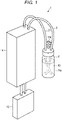
- FIG. 1 is a perspective diagram illustrating a configuration of the ink jet recording apparatus 1 according to the first embodiment.
- FIG. 2 is an explanatory diagram illustrating the configuration of the ink jet recording apparatus 1.
- FIG. 3 is a block diagram illustrating the configuration of the ink jet recording apparatus 1.
- the ink jet recording apparatus 1 includes one or more tanks 11, a liquid discharge head 12, the ink circulation device 13 configured to circulate an ink (liquid) 90 between the tank 11 and the liquid discharge head 12, a case 14 configured to contain the ink circulation device 13, a central processing unit (CPU) 15 that is a processor (a control unit), a program memory 16, a random access memory (RAM) 17, a communication interface (I/F) 18, a head controller 19, and a control board 20.
- CPU central processing unit
- CPU central processing unit
- CPU central processing unit
- program memory 16 a random access memory
- I/F communication interface
- head controller 19 a control board 20.
- the number of the tanks 11 to be provided is the same as the number of types of the ink 90 to be discharged by the ink jet recording apparatus 1.
- the types of the ink 90 refer to a color, a characteristic, and the like of the ink 90.
- descriptions are given of the ink jet recording apparatus 1 configured to discharge one color of the ink 90. Therefore, one tank 11 is provided.
- the tank 11 is filled with the ink 90 and attached to the ink circulation device 13.
- the tank 11 may be a container used repeatedly, capable of being refilled with the ink 90 when a remaining amount of the ink 90 decreases.
- the tank 11 may be a disposable type container, which is replaced with a container filled with the ink 90 when the remaining amount of the ink 90 decreases.
- the tank 11 includes a tank body 11a and an air filter 11b provided on the tank body 11a.
- the tank body 11a communicates with an atmosphere via the air filter 11b.
- the liquid discharge head 12 discharges one or two colors of the inks 90.
- the ink jet recording apparatus 1 is configured to discharge one color of the ink 90. Therefore, the liquid discharge head 12 configured to discharge one color of the ink 90 will be described.
- the liquid discharge head 12 includes one or more rows of nozzle arrays 12b in which a plurality of nozzle holes 12a are arranged in one direction.
- an actuator including a piezoelectric element or a diaphragm is driven, a plurality of pressure chambers 12c of the actuator disposed to be opposed to a nozzle plate including the nozzle array 12b. Accordingly, the liquid discharge head 12 jets the ink 90 of the pressure chamber 12c to a recording medium from the nozzle holes 12a opposed to the pressure chambers 12c.
- the liquid discharge head 12 internally includes an ink flow channel configured to supply the ink 90 to each pressure chamber 12c, a supply port 12d provided on a primary side of the ink flow channel, and a discharge port 12e provided on a secondary side of the ink flow channel.
- One or more of the supply port 12d and the discharge port 12e are provided depending on the number of the nozzle holes 12a or the number of rows of the nozzle arrays 12b.
- the liquid discharge head 12 is disposed, for example, in a posture in which the plurality of nozzle holes 12a opens downward in a direction of gravity.
- the ink circulation device 13 includes a first flow channel pipe 21, a first pump 22, a first diameter expanded portion 23, a first pressure sensor 24, a first valve 25, a second flow channel pipe 31, a second pump 32, a second diameter expanded portion 33, a second pressure sensor 34, a second valve 35, a heater 36, a first temperature sensor 37, and a second temperature sensor 38.
- a primary side of the first flow channel pipe 21 is connected to the tank 11, and a secondary side thereof is connected to the supply port 12d of the liquid discharge head 12.
- the first flow channel pipe 21 is, for example, a tube formed of a resin material.
- the first flow channel pipe 21 is configured of, for example, a plurality of tubes formed to have a predetermined length, and the tubes can be connected to respective components by so-called pipe connection.
- the first pump 22 is, for example, a diaphragm pump.
- the first pump 22 supplies the ink 90 of the tank 11 to the liquid discharge head 12.
- the first pump 22 is provided midway through the first flow channel pipe 21.
- the first diameter expanded portion 23 is provided midway through the first flow channel pipe 21 on a secondary side of the first pump 22.
- the first diameter expanded portion 23 is formed such that a flow channel cross-sectional area perpendicular to a flow direction of the ink 90 is larger than a flow channel cross-sectional area of the first flow channel pipe 21 perpendicular to the flow direction of the ink 90, and the first diameter expanded portion 23 is formed to have a predetermined length in the flow direction of the ink 90. That is, the first diameter expanded portion 23 forms a liquid chamber of which a flow channel cross-sectional area is larger than the flow channel cross-sectional area of the first flow channel pipe 21, between the first pump 22 and the liquid discharge head 12.
- the first diameter expanded portion 23 reduces pulsation of the ink 90 which is discharged from the first pump 22 on the primary side to be supplied from the first flow channel pipe 21 to the liquid discharge head 12.
- the liquid chamber formed by the first diameter expanded portion 23 may have a cylindrical shape, a rectangular columnar shape, or any other shape, as long as the pulsation of the ink 90 can be reduced.
- the first diameter expanded portion 23 is, for example, disposed side by side with the first pump 22 along the direction of gravity.
- the first pressure sensor 24 is provided on the first flow channel pipe 21 on a secondary side of the first diameter expanded portion 23.
- the first pressure sensor 24 detects a pressure of the ink 90 of the first flow channel pipe 21 on the secondary side of the first diameter expanded portion 23.
- the first valve 25 is provided on the first flow channel pipe 21 on the secondary side of the first diameter expanded portion 23.
- the first valve 25 is provided between the first flow channel pipe 21 and the first pressure sensor 24.
- the first valve 25 is a solenoid valve that opens and closes a flow channel of the first flow channel pipe 21 on the secondary side of the first diameter expanded portion 23.
- the first valve 25 is a pressure adjustment mechanism that adjusts the pressure in the first flow channel pipe 21 by opening and closing.
- a primary side of the second flow channel pipe 31 is connected to the discharge port 12e of the liquid discharge head 12, and a secondary side thereof is connected to the tank 11.
- the second flow channel pipe 31 is, for example, a tube formed of a resin material.
- the second flow channel pipe 31 is configured of, for example, a plurality of tubes formed to have a predetermined length, and the tubes can be connected to respective components by so-called pipe connection.
- the second pump 32 is, for example, a diaphragm pump.
- the second pump 32 returns the ink 90, which flows in the ink flow channel in the liquid discharge head 12 and is not discharged by the liquid discharge head 12, to the tank 11.
- the second pump 32 is provided midway through the second flow channel pipe 31.
- the second diameter expanded portion 33 is provided midway through the second flow channel pipe 31 on a primary side of the second pump 32.
- the second diameter expanded portion 33 is formed such that a flow channel cross-sectional area perpendicular to the flow direction of the ink 90 is larger than a flow channel cross-sectional area of the second flow channel pipe 31 perpendicular to the flow direction of the ink 90, and the second diameter expanded portion 33 is formed to have a predetermined length in the flow direction of the ink 90. That is, the second diameter expanded portion 33 forms a liquid chamber of which a flow channel cross-sectional area is larger than the flow channel cross-sectional area of the second flow channel pipe 31, between the liquid discharge head 12 and the second pump 32.
- the second diameter expanded portion 33 reduces the pulsation of the ink 90 which was discharged from the liquid discharge head 12 and sucked into the second pump 32 on a secondary side.
- the liquid chamber formed by the second diameter expanded portion 33 may have a cylindrical shape, a rectangular columnar shape, or any other shape, as long as the pulsation of the ink 90 can be reduced.
- the second diameter expanded portion 33 is, for example, disposed side by side with the second pump 32 along the direction of gravity.
- the second pressure sensor 34 is provided on the second flow channel pipe 31, on a secondary side of the liquid discharge head 12 and a primary side of the second diameter expanded portion 33.
- the second pressure sensor 34 detects a pressure of the ink 90 of the second flow channel pipe 31, on the secondary side of the liquid discharge head 12 and the primary side of the second diameter expanded portion 33.
- the second valve 35 is provided on the second flow channel pipe 31, on the secondary side of the liquid discharge head 12 and the primary side of the second diameter expanded portion 33.
- the second valve 35 is provided between the second flow channel pipe 31 and the second pressure sensor 34.
- the second valve 35 is a solenoid valve that opens and closes a flow channel of the second flow channel pipe 31 on the secondary side of the second diameter expanded portion 33.
- the second valve 35 is a pressure adjustment mechanism that adjusts the pressure in the second flow channel pipe 31 by opening and closing.
- the heater 36 includes a heating unit configured to heat a heating object by generating heat.
- the heating unit of the heater 36 is attached to the heating object.
- the heater 36 is provided on the secondary side of the first pump 22 and a primary side of the supply port 12d of the liquid discharge head 12.
- the heater 36 is provided on the first flow channel pipe 21, on the secondary side of the first pump 22 and a primary side of the first diameter expanded portion 23. The heater 36 heats the ink 90 flowing through the first flow channel pipe 21 by heating the first flow channel pipe 21.
- the first temperature sensor 37 is provided on a secondary side of the discharge port 12e of the liquid discharge head 12 and a primary side of the second pump 32.
- the first temperature sensor 37 is provided on the second diameter expanded portion 33 and detects the temperature of the ink 90 in the second diameter expanded portion 33.
- the first temperature sensor 37 is electrically connected to the CPU 15, and transmits detected temperature information (a detected value) to the CPU 15 as an electric signal.
- the first temperature sensor 37 is, for example, a thermistor.
- the second temperature sensor 38 is provided on the heater 36.
- the second temperature sensor 38 detects the temperature of the heater 36.
- the second temperature sensor 38 is electrically connected to the CPU 15, and transmits detected temperature information (a detected value) to the CPU 15 as an electric signal.
- the second temperature sensor 38 is, for example, a thermistor.
- the case 14 is formed to have a rectangular parallelepiped shape having a predetermined volume of a containing space therein.
- the case 14 contains each component except for both ends of the first flow channel pipe 21 and the second flow channel pipe 31 of the ink circulation device 13, respectively connected to the tank 11 and the liquid discharge head 12.
- the CPU 15 controls, for example, the whole ink jet recording apparatus 1.
- the CPU 15 realizes various processes by executing a program.
- the CPU 15 is electrically connected to the program memory 16, the RAM 17, the communication I/F 18, the head controller 19, and the control board 20 in the ink jet recording apparatus 1.
- the CPU 15 is configured to output an operation instruction to each unit of the ink jet recording apparatus 1 according to an operation command from an external device and to notify the external device of various information acquired from each unit.
- the CPU 15 performs various processes by using the RAM 17 and executing a program stored in the program memory 16.
- the program memory 16 is a storage unit.
- the program memory 16 is, for example, a read only memory (ROM), and is a non-rewritable nonvolatile memory that stores a program, control data, and the like.
- ROM read only memory
- the RAM 17 is a storage unit.
- the RAM 17 is formed of a volatile memory.
- the RAM 17 is, for example, a working memory.
- the RAM 17 stores, for example, a setting value used when the heater 36 heats the ink 90.
- the RAM 17 stores, as the setting value used when heating the ink 90, a target temperature of the ink 90 and a threshold value which is a temperature (an upper limit temperature) with which the heater 36 is determined to be abnormal.
- the threshold value an upper limit value of the temperature of the heater 36 itself is set.
- the threshold value is appropriately set considering the type of the ink 90, a peripheral configuration, safety, and the like.
- the threshold value is the temperature of the heater 36 which can avoid damage to peripheral parts existing around the heater 36 or destruction of the device.
- the communication I/F 18 is an interface configured to communicate with the external device such as a host control device 100.
- the communication I/F 18 receives printing data in response to a print request from the external device.
- the communication I/F 18 is electrically connected to the CPU 15 and configures an interface that transmits and receives data to and from the external device.
- the head controller 19 drives the liquid discharge head 12 based on an instruction from the CPU 15.
- the head controller 19 is electrically connected to a drive circuit 12f of the liquid discharge head 12.
- the CPU 15, the program memory 16, the RAM 17, the communication I/F 18, and the head controller 19 are mounted on the control board 20.
- the control board 20 is contained, for example, in the case 14, and electrically connected to the first pump 22, the first pressure sensor 24, the first valve 25, the second pump 32, the second pressure sensor 34, and the second valve 35.
- the control board 20 includes a drive circuit 20a that receives a signal of a pressure value transmitted from the first pressure sensor 24 and the second pressure sensor 34 and drives and controls the first pump 22, the first valve 25, the second pump 32, and the second valve 35.
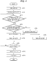
- FIG. 4 is a flowchart illustrating a flow of a process of controlling the temperature of the ink 90 of the ink circulation device 13 provided on the ink jet recording apparatus 1.
- the CPU 15 drives the ink circulation device 13 and circulates the ink (liquid) 90 between the tank 11 and the liquid discharge head 12 (Act 1).
- the CPU 15 drives the first pump 22 and the second pump 32, supplies the ink 90 in the tank 11 to the liquid discharge head 12, and returns the ink of the liquid discharge head 12 to the tank 11.
- the CPU 15 determines whether the temperature (a detected value) detected by the first temperature sensor 37 is equal to or lower than the target temperature of the ink 90 stored in the RAM 17 (Act 3). If the temperature of the ink 90, detected by the first temperature sensor 37 is higher than the target temperature of the ink 90 (NO in Act 3), the CPU 15 turns the heater 36 off or keeps the heater 36 off (Act 4).
- the CPU 15 determines whether the temperature (a detected value) of the heater 36 detected by the second temperature sensor 38 is equal to or less than threshold value stored in the RAM 17 (Act 5). If the temperature of the heater 36 detected by the second temperature sensor 38 is higher than the threshold value (NO in Act 5), the CPU 15 determines that the heater 36 is abnormal (Act 6) and turns the heater 36 off or keeps the heater 36 off (Act 4). If the temperature of the heater 36, detected by the second temperature sensor 38 is equal to or lower than the threshold value (YES in Act 5), the CPU 15 determines that the heater 36 is normal (Act 7) and turns the heater 36 on or keeps the heater 36 on (Act 8).
- the CPU 15 determines whether there is a stop instruction (Act 9).
- the stop instruction include an external command from the host control device 100 or the like and a stop instruction issued by a program or the like when an abnormality in the temperature detected by the first temperature sensor 37 and the second temperature sensor 38 is detected.
- the stop instruction include an instruction to stop the heating of the ink 90 by the heater 36 and an instruction to stop the circulation of the ink 90.
- the stop instruction is, for example, an instruction to stop the circulation of the ink 90 from the host control device 100.
- the process returns to Act 3, and the CPU 15 repeatedly performs the heating control processes of the ink 90. If there is the instruction to stop the circulation of the ink 90 (YES in Act 9), the CPU 15 turns the heater 36 off or keeps the heater 36 off (Act 10), and stops the first pump 22 and the second pump 32 (Act 11).
- the ink jet recording apparatus 1 configured in this manner includes the heater 36 provided on the first flow channel pipe 21, on the primary side of the liquid discharge head 12 and the secondary side of the first pump 22. Accordingly, the ink 90 supplied to the liquid discharge head 12 can be heated.
- the ink jet recording apparatus 1 is provided with the first temperature sensor 37 on the secondary side of the liquid discharge head 12, and configured to heat the ink 90 by the heater 36 if the temperature detected by the first temperature sensor 37 is equal to or lower than the target temperature of the ink 90.
- the ink jet recording apparatus 1 having the configuration can control the heater 36 based on the temperature of the ink 90 detected by the first temperature sensor 37 correlated with the temperature of the ink 90 in the liquid discharge head 12.
- FIG. 5 is an explanatory diagram illustrating the temperature of the ink 90 detected by the first temperature sensor 37 as a solid line, and illustrating the temperature of the ink 90 in the liquid discharge head 12 detected by a thermistor provided in the liquid discharge head 12 as a broken line. As illustrated in FIG. 5 , it can be seen that there is a correlation between the temperature of the second diameter expanded portion 33 detected by the first temperature sensor 37, and the temperature of the ink 90 in the liquid discharge head 12 detected by the thermistor.
- the ink jet recording apparatus 1 controls on and off of the heater 36 based on the temperature of the ink 90 detected by the first temperature sensor 37. Accordingly, the heater 36 can be controlled based on the temperature of the ink 90 even if a unit configured to detect a temperature such as a temperature sensor is not provided on the liquid discharge head 12.
- the ink jet recording apparatus 1 can perform feedback control to control the heater 36 by comparing the temperature of the ink 90 detected by the first temperature sensor 37 with the target temperature. In this manner, the ink jet recording apparatus 1 can manage the temperature of the ink 90 such that the ink 90 has an appropriate viscosity. As a result, since the liquid discharge head 12 can discharge the ink 90 accurately and stably, the ink jet recording apparatus 1 can obtain high printing performance.
- the ink jet recording apparatus 1 determines that the heater 36 is abnormal and turns the heater 36 off. According to the configuration, the ink jet recording apparatus 1 can avoid damage to a peripheral part existing around the heater 36 or destruction of the device due to excessive heating by abnormal heating of the heater 36. As a result, the ink jet recording apparatus 1 can ensure high safety. As described above, according to the ink jet recording apparatus 1 according to an exemplary embodiment, the liquid (ink 90) can be heated to an appropriate temperature.
- the present disclosure is not limited to the exemplary embodiments, the scope of the invention is defined by the claims.
- the ink jet recording apparatus 1 may have a configuration capable of discharging various types of ink.
- two tanks 11, one liquid discharge head 12A, and two ink circulation devices 13 configured to circulate the two tanks 11 and the liquid discharge head 12A may be provided to discharge two different types of the ink 90.
- an ink jet recording apparatus configured to jet four colors of the ink 90 may include four tanks 11, two liquid discharge heads 12A, four ink circulation devices 13, and two cases 14. That is, according to the color and type of the ink 90 to be used, an ink jet recording apparatus capable of jetting multi-kinds or multi-colors of the ink 90 can be provided by appropriately combining the components.
- the RAM 17 stores the target temperature and the threshold value of the ink 90
- the threshold value used for determining the abnormality of the heater 36 may be stored in the program memory 16 to obtain a configuration in which the threshold value cannot be set.
- the target temperature of the ink 90 may be rewritable by setting by the host control device 100 or the like.
- the CPU 15 may change the heating temperature of the heater 36. If the configuration is adopted, the CPU 15 may perform feedback control to change the heating temperature of the heater 36 based on the temperature of the ink 90 detected by the first temperature sensor 37.
- a moving mechanism configured to move the liquid discharge head 12 may further be provided.
- a transport motor configured to transport the recording medium, a carriage motor configured to control a position of the liquid discharge head 12, and the like may further be provided.
- the liquid used in the ink jet recording apparatuses 1 and 1A is not limited to the ink 90, and the present disclosure can be applied for a liquid discharge device that discharges a liquid other than the ink 90. Examples of the liquid discharge device using the liquid other than the ink 90 may include a device that discharges a liquid containing conductive particles configured to form a wiring pattern of a printed wiring board.
- the liquid discharge device can be used, for example, in a 3D printer, an industrial manufacturing machine, and a medical application.
- the actuator of the liquid discharge head 12 may be configured to change the pressure chamber 12c by electrically deforming the diaphragm and may be configured to discharge the ink 90 from the nozzle using thermal energy of heater and the like.
- the CPU 15 determines the normal or abnormal of the heater 36 by determining the temperature of the heater 36 detected by the second temperature sensor 38 and the threshold value, but the present disclosure is not limited thereto.
- the CPU 15 may transmit the determined information to the host control device 100 and display a state of the heater 36 on the host control device 100.
- liquid discharge device 1 including the program memory 16 and the RAM 17 as a storage unit.
- the present disclosure is not limited thereto, and another storage device may be provided.
- the CPU 15 controls the whole ink jet recording apparatus 1, but the present disclosure is not limited thereto.
- the CPU 15 may control only the ink circulation device 13 and the other configurations in the ink jet recording apparatus 1 may be processed by a processing device that is a processor other than the CPU 15.
- a description was given of a configuration using the CPU 15 as the processor, but the processor is not limited to the CPU 15 and can be set as appropriate.
- the liquid can be heated to an appropriate temperature.
Landscapes
- Ink Jet (AREA)
Claims (6)
- Tintenzirkulationsvorrichtung (13), umfassend:ein erstes Strömungskanalrohr (21), von dem eine sekundäre Seite mit einem Tintenausstoßkopf (12) verbunden ist, der konfiguriert ist, um Tinte auszustoßen;eine erste Pumpe (22), die im ersten Strömungskanalrohr bereitgestellt ist,einen ersten Abschnitt mit erweitertem Durchmesser (23), der im ersten Strömungskanalrohr auf der sekundären Seite der ersten Pumpe bereitgestellt ist, wobei der erste Abschnitt mit erweitertem Durchmesser einen Strömungskanal-Querschnittsbereich umfasst, der größer als ein Strömungskanal-Querschnittsbereich des ersten Strömungskanalrohrs ist;ein zweites Strömungskanalrohr (31), von dem eine primäre Seite mit dem Tintenausstoßkopf verbunden ist;eine zweite Pumpe (32), die in dem zweiten Strömungskanalrohr bereitgestellt ist;einen zweiten Abschnitt mit erweitertem Durchmesser (33), der in dem zweiten Strömungskanalrohr auf der primären Seite der zweiten Pumpe bereitgestellt ist, wobei der zweite Abschnitt mit erweitertem Durchmesser einen Strömungskanal-Querschnittsbereich beinhaltet, der grösser als ein Strömungskanal-Querschnittsbereich des zweitem Strömungskanalrohrs ist,eine Heizvorrichtung (36), die auf der sekundären Seite der ersten Pumpe und der primären Seite des ersten Abschnitts mit erweitertem Durchmesser bereitgestellt und konfiguriert ist, um die Tinte, die durch das erste Strömungskanalrohr fließt, zu erwärmen;einen Heizvorrichtungs-Temperatursensor (38), der auf der Heizvorrichtung bereitgestellt und konfiguriert ist, um eine Temperatur auf der Heizvorrichtung nachzuweisen;einen Temperatursensor (37), der auf dem zweiten Abschnitt mit erweitertem Durchmesser bereitgestellt und konfiguriert ist, um eine Temperatur der Tinte im zweiten Abschnitt mit erweitertem Durchmesser nachzuweisen:eine Speichereinheit (17), die konfiguriert ist, um eine Zieltemperatur der Tinte und eine obere Grenztemperatur der Heizvorrichtung zu speichern; undeine Steuereinheit (15), die konfiguriert ist, um die Heizvorrichtung basierend auf Ergebnissen des Vergleichens eines nachgewiesenen Werts, nachgewiesen durch den Temperatursensor und die Zieltemperatur, und des Vergleichens einer Heizvorrichtungstemperatur, nachgewiesen durch den Heizvorrichtungs-Temperatursensor und der oberen Grenztemperatur der Heizvorrichtung.
- Tintenzirkulationsvorrichtung nach Anspruch 1, wobei die Steuereinheit weiter konfiguriert ist, um die Heizvorrichtung einzuschalten und die Heizvorrichtung eingeschaltet zu halten, wenn der nachgewiesene Wert, nachgewiesen durch den Temperatursensor, gleich wie oder geringer als die Zieltemperatur ist, und die Heizvorrichtungstemperatur, nachgewiesen durch den Heizvorrichtungs-Temperatursensor, gleich wie oder geringer als die obere Grenztemperatur der Heizvorrichtung ist.
- Tintenzirkulationsvorrichtung nach Anspruch 1 oder 2, wobei
die Steuereinheit die Heizvorrichtung daran hindert, die Tinte zu erwärmen, wenn die Heizvorrichtungstemperatur, nachgewiesen durch den Heizvorrichtungs-Temperatursensor die obere Grenztemperatur der Heizvorrichtung übersteigt. - Tintenzirkulationsvorrichtung nach einem der Ansprüche 1 bis 3, weiter umfassend:einen ersten Drucksensor (24), der Druck der Tinte im ersten Strömungskanalrohr nachweist; undeinen zweiten Drucksensor (34), der Druck der Tinte im zweiten Strömungskanalrohr nachweist.
- Tintenausstoßvorrichtung (1) umfassend:einen Tintenausstoßkopf (12), der konfiguriert ist, um Tinte auszustoßen; unddie Tintenzirkulationsvorrichtung (13) nach einem der Ansprüche 1 bis 4.
- Tintenstrahldrucker, umfassend:eine Papierkassette;einen Papierfördermechanismus; undeine Tintenausstoßvorrichtung nach Anspruch 5.
Applications Claiming Priority (1)
| Application Number | Priority Date | Filing Date | Title |
|---|---|---|---|
| JP2018193691A JP7118850B2 (ja) | 2018-10-12 | 2018-10-12 | 液体循環装置及び液体吐出装置 |
Publications (2)
| Publication Number | Publication Date |
|---|---|
| EP3636441A1 EP3636441A1 (de) | 2020-04-15 |
| EP3636441B1 true EP3636441B1 (de) | 2022-11-30 |
Family
ID=67998335
Family Applications (1)
| Application Number | Title | Priority Date | Filing Date |
|---|---|---|---|
| EP19198660.3A Active EP3636441B1 (de) | 2018-10-12 | 2019-09-20 | Tintenzirkulationsvorrichtung und tintenausstossvorrichtung |
Country Status (4)
| Country | Link |
|---|---|
| US (1) | US10987923B2 (de) |
| EP (1) | EP3636441B1 (de) |
| JP (1) | JP7118850B2 (de) |
| CN (1) | CN111038106B (de) |
Families Citing this family (5)
| Publication number | Priority date | Publication date | Assignee | Title |
|---|---|---|---|---|
| WO2021214988A1 (ja) * | 2020-04-24 | 2021-10-28 | 株式会社Fuji | インクジェット装置の制御方法及びインクジェット装置 |
| US12545023B2 (en) | 2020-07-02 | 2026-02-10 | Samsung Display Co., Ltd. | Inkjet printing apparatus and method for manufacturing display device |
| US11697289B2 (en) * | 2020-12-01 | 2023-07-11 | Toshiba Tec Kabushiki Kaisha | Liquid circulation device and liquid discharge apparatus |
| JP7640351B2 (ja) * | 2020-12-01 | 2025-03-05 | 理想テクノロジーズ株式会社 | 液体循環装置及び液体吐出装置 |
| EP4370345B1 (de) * | 2021-07-12 | 2025-12-17 | Bobst Mex Sa | Tintenstrahldrucksystem und verfahren zur steuerung der strahltemperatur |
Family Cites Families (14)
| Publication number | Priority date | Publication date | Assignee | Title |
|---|---|---|---|---|
| JP4971942B2 (ja) * | 2007-10-19 | 2012-07-11 | 富士フイルム株式会社 | インクジェット記録装置及び記録方法 |
| KR20100092223A (ko) * | 2009-02-12 | 2010-08-20 | 삼성전자주식회사 | 어레이형 헤드를 구비하는 잉크젯 프린터 및 그 구동방법 |
| JP2011031397A (ja) * | 2009-07-29 | 2011-02-17 | Olympus Corp | 画像記録装置 |
| JP2011051170A (ja) * | 2009-08-31 | 2011-03-17 | Seiko Epson Corp | 液体噴射装置 |
| JP2014079885A (ja) * | 2012-10-12 | 2014-05-08 | Toshiba Corp | インクジェット印字装置及びそのインク循環制御方法 |
| JP2014144611A (ja) * | 2013-01-30 | 2014-08-14 | Fujifilm Corp | インクジェット記録装置及びインク充填方法 |
| JP5877170B2 (ja) * | 2013-03-21 | 2016-03-02 | 富士フイルム株式会社 | インクジェット記録装置 |
| US9352555B2 (en) * | 2013-09-06 | 2016-05-31 | Riso Kagaku Corporation | Inkjet printer |
| JP2015107599A (ja) * | 2013-12-05 | 2015-06-11 | 東芝テック株式会社 | インクジェット記録装置 |
| JP2017007108A (ja) * | 2015-06-17 | 2017-01-12 | 東芝テック株式会社 | インク循環装置及びインクジェット記録装置 |
| WO2016208533A1 (ja) * | 2015-06-26 | 2016-12-29 | 積水化学工業株式会社 | インクジェット印刷装置及び印刷方法 |
| US9815287B2 (en) | 2016-01-08 | 2017-11-14 | Canon Kabushiki Kaisha | Liquid discharge head and liquid discharge apparatus |
| JP6983504B2 (ja) * | 2016-01-08 | 2021-12-17 | キヤノン株式会社 | 液体吐出ヘッド及び液体吐出装置 |
| JP6695154B2 (ja) | 2016-01-28 | 2020-05-20 | 東芝テック株式会社 | インク循環装置及びプリンタ |
-
2018
- 2018-10-12 JP JP2018193691A patent/JP7118850B2/ja active Active
-
2019
- 2019-08-07 CN CN201910725048.1A patent/CN111038106B/zh active Active
- 2019-08-26 US US16/550,504 patent/US10987923B2/en active Active
- 2019-09-20 EP EP19198660.3A patent/EP3636441B1/de active Active
Also Published As
| Publication number | Publication date |
|---|---|
| JP2020059256A (ja) | 2020-04-16 |
| CN111038106A (zh) | 2020-04-21 |
| US10987923B2 (en) | 2021-04-27 |
| EP3636441A1 (de) | 2020-04-15 |
| JP7118850B2 (ja) | 2022-08-16 |
| CN111038106B (zh) | 2022-01-21 |
| US20200114644A1 (en) | 2020-04-16 |
Similar Documents
| Publication | Publication Date | Title |
|---|---|---|
| EP3636441B1 (de) | Tintenzirkulationsvorrichtung und tintenausstossvorrichtung | |
| TWI564165B (zh) | 流體噴出列印頭、流體噴出裝置、及透過列印頭用於單側熱感測之方法 | |
| US8870325B2 (en) | Compensating for capacitance changes in piezoelectric printhead elements | |
| CN106256551B (zh) | 油墨循环装置及喷墨式记录装置 | |
| JP6978338B2 (ja) | 液体循環装置、及び液体吐出装置 | |
| EP3426493A1 (de) | Kalibrierung eines druckkopfes | |
| US8491075B2 (en) | Method and apparatus for controlling jetting performance in an inkjet printer | |
| EP4008557B1 (de) | Flüssigkeitszirkulationsvorrichtung und flüssigkeitsausgabevorrichtung | |
| JP2018144419A (ja) | インクジェット記録装置及びインクジェット記録装置の制御方法 | |
| JP2003136756A (ja) | インクジェットプリンタ | |
| JP7764260B2 (ja) | 液体循環装置及び液体吐出装置 | |
| JP3402766B2 (ja) | 記録装置、該記録装置の制御方法および記録方法 | |
| JP6506620B2 (ja) | 記録装置、及び、記録ヘッドの温度制御方法 | |
| WO2017188993A1 (en) | Selectively firing a fluid circulation element | |
| JP2009012188A (ja) | インクジェット記録装置 | |
| JP7062458B2 (ja) | 液体吐出装置 | |
| CN115817021B (zh) | 液体循环装置以及液体喷出装置 | |
| JP7242810B2 (ja) | 液体循環装置、及び液体吐出装置 | |
| US20210237438A1 (en) | Inkjet printer and control method of inkjet printer | |
| JP2022087786A (ja) | 液体循環装置及び液体吐出装置 | |
| JP5190337B2 (ja) | 画像記録装置、及び画像記録装置のインク温度制御方法 | |
| JP6164913B2 (ja) | インクジェット記録装置及び記録方法 |
Legal Events
| Date | Code | Title | Description |
|---|---|---|---|
| PUAI | Public reference made under article 153(3) epc to a published international application that has entered the european phase |
Free format text: ORIGINAL CODE: 0009012 |
|
| STAA | Information on the status of an ep patent application or granted ep patent |
Free format text: STATUS: THE APPLICATION HAS BEEN PUBLISHED |
|
| AK | Designated contracting states |
Kind code of ref document: A1 Designated state(s): AL AT BE BG CH CY CZ DE DK EE ES FI FR GB GR HR HU IE IS IT LI LT LU LV MC MK MT NL NO PL PT RO RS SE SI SK SM TR |
|
| AX | Request for extension of the european patent |
Extension state: BA ME |
|
| STAA | Information on the status of an ep patent application or granted ep patent |
Free format text: STATUS: REQUEST FOR EXAMINATION WAS MADE |
|
| 17P | Request for examination filed |
Effective date: 20201015 |
|
| RBV | Designated contracting states (corrected) |
Designated state(s): AL AT BE BG CH CY CZ DE DK EE ES FI FR GB GR HR HU IE IS IT LI LT LU LV MC MK MT NL NO PL PT RO RS SE SI SK SM TR |
|
| GRAP | Despatch of communication of intention to grant a patent |
Free format text: ORIGINAL CODE: EPIDOSNIGR1 |
|
| STAA | Information on the status of an ep patent application or granted ep patent |
Free format text: STATUS: GRANT OF PATENT IS INTENDED |
|
| INTG | Intention to grant announced |
Effective date: 20220614 |
|
| GRAS | Grant fee paid |
Free format text: ORIGINAL CODE: EPIDOSNIGR3 |
|
| GRAA | (expected) grant |
Free format text: ORIGINAL CODE: 0009210 |
|
| STAA | Information on the status of an ep patent application or granted ep patent |
Free format text: STATUS: THE PATENT HAS BEEN GRANTED |
|
| AK | Designated contracting states |
Kind code of ref document: B1 Designated state(s): AL AT BE BG CH CY CZ DE DK EE ES FI FR GB GR HR HU IE IS IT LI LT LU LV MC MK MT NL NO PL PT RO RS SE SI SK SM TR |
|
| REG | Reference to a national code |
Ref country code: CH Ref legal event code: EP Ref country code: GB Ref legal event code: FG4D |
|
| REG | Reference to a national code |
Ref country code: AT Ref legal event code: REF Ref document number: 1534386 Country of ref document: AT Kind code of ref document: T Effective date: 20221215 |
|
| REG | Reference to a national code |
Ref country code: IE Ref legal event code: FG4D |
|
| REG | Reference to a national code |
Ref country code: DE Ref legal event code: R096 Ref document number: 602019022456 Country of ref document: DE |
|
| REG | Reference to a national code |
Ref country code: LT Ref legal event code: MG9D |
|
| REG | Reference to a national code |
Ref country code: NL Ref legal event code: MP Effective date: 20221130 |
|
| PG25 | Lapsed in a contracting state [announced via postgrant information from national office to epo] |
Ref country code: SE Free format text: LAPSE BECAUSE OF FAILURE TO SUBMIT A TRANSLATION OF THE DESCRIPTION OR TO PAY THE FEE WITHIN THE PRESCRIBED TIME-LIMIT Effective date: 20221130 Ref country code: PT Free format text: LAPSE BECAUSE OF FAILURE TO SUBMIT A TRANSLATION OF THE DESCRIPTION OR TO PAY THE FEE WITHIN THE PRESCRIBED TIME-LIMIT Effective date: 20230331 Ref country code: NO Free format text: LAPSE BECAUSE OF FAILURE TO SUBMIT A TRANSLATION OF THE DESCRIPTION OR TO PAY THE FEE WITHIN THE PRESCRIBED TIME-LIMIT Effective date: 20230228 Ref country code: LT Free format text: LAPSE BECAUSE OF FAILURE TO SUBMIT A TRANSLATION OF THE DESCRIPTION OR TO PAY THE FEE WITHIN THE PRESCRIBED TIME-LIMIT Effective date: 20221130 Ref country code: FI Free format text: LAPSE BECAUSE OF FAILURE TO SUBMIT A TRANSLATION OF THE DESCRIPTION OR TO PAY THE FEE WITHIN THE PRESCRIBED TIME-LIMIT Effective date: 20221130 Ref country code: ES Free format text: LAPSE BECAUSE OF FAILURE TO SUBMIT A TRANSLATION OF THE DESCRIPTION OR TO PAY THE FEE WITHIN THE PRESCRIBED TIME-LIMIT Effective date: 20221130 |
|
| REG | Reference to a national code |
Ref country code: AT Ref legal event code: MK05 Ref document number: 1534386 Country of ref document: AT Kind code of ref document: T Effective date: 20221130 |
|
| PG25 | Lapsed in a contracting state [announced via postgrant information from national office to epo] |
Ref country code: RS Free format text: LAPSE BECAUSE OF FAILURE TO SUBMIT A TRANSLATION OF THE DESCRIPTION OR TO PAY THE FEE WITHIN THE PRESCRIBED TIME-LIMIT Effective date: 20221130 Ref country code: PL Free format text: LAPSE BECAUSE OF FAILURE TO SUBMIT A TRANSLATION OF THE DESCRIPTION OR TO PAY THE FEE WITHIN THE PRESCRIBED TIME-LIMIT Effective date: 20221130 Ref country code: LV Free format text: LAPSE BECAUSE OF FAILURE TO SUBMIT A TRANSLATION OF THE DESCRIPTION OR TO PAY THE FEE WITHIN THE PRESCRIBED TIME-LIMIT Effective date: 20221130 Ref country code: IS Free format text: LAPSE BECAUSE OF FAILURE TO SUBMIT A TRANSLATION OF THE DESCRIPTION OR TO PAY THE FEE WITHIN THE PRESCRIBED TIME-LIMIT Effective date: 20230330 Ref country code: HR Free format text: LAPSE BECAUSE OF FAILURE TO SUBMIT A TRANSLATION OF THE DESCRIPTION OR TO PAY THE FEE WITHIN THE PRESCRIBED TIME-LIMIT Effective date: 20221130 Ref country code: GR Free format text: LAPSE BECAUSE OF FAILURE TO SUBMIT A TRANSLATION OF THE DESCRIPTION OR TO PAY THE FEE WITHIN THE PRESCRIBED TIME-LIMIT Effective date: 20230301 |
|
| PG25 | Lapsed in a contracting state [announced via postgrant information from national office to epo] |
Ref country code: NL Free format text: LAPSE BECAUSE OF FAILURE TO SUBMIT A TRANSLATION OF THE DESCRIPTION OR TO PAY THE FEE WITHIN THE PRESCRIBED TIME-LIMIT Effective date: 20221130 |
|
| PG25 | Lapsed in a contracting state [announced via postgrant information from national office to epo] |
Ref country code: SM Free format text: LAPSE BECAUSE OF FAILURE TO SUBMIT A TRANSLATION OF THE DESCRIPTION OR TO PAY THE FEE WITHIN THE PRESCRIBED TIME-LIMIT Effective date: 20221130 Ref country code: RO Free format text: LAPSE BECAUSE OF FAILURE TO SUBMIT A TRANSLATION OF THE DESCRIPTION OR TO PAY THE FEE WITHIN THE PRESCRIBED TIME-LIMIT Effective date: 20221130 Ref country code: EE Free format text: LAPSE BECAUSE OF FAILURE TO SUBMIT A TRANSLATION OF THE DESCRIPTION OR TO PAY THE FEE WITHIN THE PRESCRIBED TIME-LIMIT Effective date: 20221130 Ref country code: DK Free format text: LAPSE BECAUSE OF FAILURE TO SUBMIT A TRANSLATION OF THE DESCRIPTION OR TO PAY THE FEE WITHIN THE PRESCRIBED TIME-LIMIT Effective date: 20221130 Ref country code: CZ Free format text: LAPSE BECAUSE OF FAILURE TO SUBMIT A TRANSLATION OF THE DESCRIPTION OR TO PAY THE FEE WITHIN THE PRESCRIBED TIME-LIMIT Effective date: 20221130 Ref country code: AT Free format text: LAPSE BECAUSE OF FAILURE TO SUBMIT A TRANSLATION OF THE DESCRIPTION OR TO PAY THE FEE WITHIN THE PRESCRIBED TIME-LIMIT Effective date: 20221130 |
|
| PG25 | Lapsed in a contracting state [announced via postgrant information from national office to epo] |
Ref country code: SK Free format text: LAPSE BECAUSE OF FAILURE TO SUBMIT A TRANSLATION OF THE DESCRIPTION OR TO PAY THE FEE WITHIN THE PRESCRIBED TIME-LIMIT Effective date: 20221130 Ref country code: AL Free format text: LAPSE BECAUSE OF FAILURE TO SUBMIT A TRANSLATION OF THE DESCRIPTION OR TO PAY THE FEE WITHIN THE PRESCRIBED TIME-LIMIT Effective date: 20221130 |
|
| REG | Reference to a national code |
Ref country code: DE Ref legal event code: R097 Ref document number: 602019022456 Country of ref document: DE |
|
| PLBE | No opposition filed within time limit |
Free format text: ORIGINAL CODE: 0009261 |
|
| STAA | Information on the status of an ep patent application or granted ep patent |
Free format text: STATUS: NO OPPOSITION FILED WITHIN TIME LIMIT |
|
| 26N | No opposition filed |
Effective date: 20230831 |
|
| PG25 | Lapsed in a contracting state [announced via postgrant information from national office to epo] |
Ref country code: SI Free format text: LAPSE BECAUSE OF FAILURE TO SUBMIT A TRANSLATION OF THE DESCRIPTION OR TO PAY THE FEE WITHIN THE PRESCRIBED TIME-LIMIT Effective date: 20221130 |
|
| REG | Reference to a national code |
Ref country code: CH Ref legal event code: PL |
|
| PG25 | Lapsed in a contracting state [announced via postgrant information from national office to epo] |
Ref country code: LU Free format text: LAPSE BECAUSE OF NON-PAYMENT OF DUE FEES Effective date: 20230920 |
|
| REG | Reference to a national code |
Ref country code: BE Ref legal event code: MM Effective date: 20230930 |
|
| PG25 | Lapsed in a contracting state [announced via postgrant information from national office to epo] |
Ref country code: LU Free format text: LAPSE BECAUSE OF NON-PAYMENT OF DUE FEES Effective date: 20230920 Ref country code: IT Free format text: LAPSE BECAUSE OF FAILURE TO SUBMIT A TRANSLATION OF THE DESCRIPTION OR TO PAY THE FEE WITHIN THE PRESCRIBED TIME-LIMIT Effective date: 20221130 Ref country code: MC Free format text: LAPSE BECAUSE OF FAILURE TO SUBMIT A TRANSLATION OF THE DESCRIPTION OR TO PAY THE FEE WITHIN THE PRESCRIBED TIME-LIMIT Effective date: 20221130 |
|
| REG | Reference to a national code |
Ref country code: IE Ref legal event code: MM4A |
|
| PG25 | Lapsed in a contracting state [announced via postgrant information from national office to epo] |
Ref country code: IE Free format text: LAPSE BECAUSE OF NON-PAYMENT OF DUE FEES Effective date: 20230920 |
|
| PG25 | Lapsed in a contracting state [announced via postgrant information from national office to epo] |
Ref country code: CH Free format text: LAPSE BECAUSE OF NON-PAYMENT OF DUE FEES Effective date: 20230930 |
|
| PG25 | Lapsed in a contracting state [announced via postgrant information from national office to epo] |
Ref country code: IE Free format text: LAPSE BECAUSE OF NON-PAYMENT OF DUE FEES Effective date: 20230920 Ref country code: CH Free format text: LAPSE BECAUSE OF NON-PAYMENT OF DUE FEES Effective date: 20230930 |
|
| PG25 | Lapsed in a contracting state [announced via postgrant information from national office to epo] |
Ref country code: BE Free format text: LAPSE BECAUSE OF NON-PAYMENT OF DUE FEES Effective date: 20230930 |
|
| REG | Reference to a national code |
Ref country code: GB Ref legal event code: 732E Free format text: REGISTERED BETWEEN 20240926 AND 20241002 |
|
| REG | Reference to a national code |
Ref country code: DE Ref legal event code: R081 Ref document number: 602019022456 Country of ref document: DE Owner name: RISO TECHNOLOGIES CORPORATION, JP Free format text: FORMER OWNER: TOSHIBA TEC KABUSHIKI KAISHA, TOKYO, JP |
|
| PG25 | Lapsed in a contracting state [announced via postgrant information from national office to epo] |
Ref country code: BG Free format text: LAPSE BECAUSE OF FAILURE TO SUBMIT A TRANSLATION OF THE DESCRIPTION OR TO PAY THE FEE WITHIN THE PRESCRIBED TIME-LIMIT Effective date: 20221130 |
|
| PG25 | Lapsed in a contracting state [announced via postgrant information from national office to epo] |
Ref country code: BG Free format text: LAPSE BECAUSE OF FAILURE TO SUBMIT A TRANSLATION OF THE DESCRIPTION OR TO PAY THE FEE WITHIN THE PRESCRIBED TIME-LIMIT Effective date: 20221130 |
|
| P01 | Opt-out of the competence of the unified patent court (upc) registered |
Free format text: CASE NUMBER: APP_68090/2024 Effective date: 20241226 |
|
| P02 | Opt-out of the competence of the unified patent court (upc) changed |
Free format text: CASE NUMBER: APP_68424/2024 Effective date: 20241227 |
|
| PG25 | Lapsed in a contracting state [announced via postgrant information from national office to epo] |
Ref country code: CY Free format text: LAPSE BECAUSE OF FAILURE TO SUBMIT A TRANSLATION OF THE DESCRIPTION OR TO PAY THE FEE WITHIN THE PRESCRIBED TIME-LIMIT; INVALID AB INITIO Effective date: 20190920 |
|
| PG25 | Lapsed in a contracting state [announced via postgrant information from national office to epo] |
Ref country code: HU Free format text: LAPSE BECAUSE OF FAILURE TO SUBMIT A TRANSLATION OF THE DESCRIPTION OR TO PAY THE FEE WITHIN THE PRESCRIBED TIME-LIMIT; INVALID AB INITIO Effective date: 20190920 |
|
| PGFP | Annual fee paid to national office [announced via postgrant information from national office to epo] |
Ref country code: DE Payment date: 20250919 Year of fee payment: 7 |
|
| PGFP | Annual fee paid to national office [announced via postgrant information from national office to epo] |
Ref country code: GB Payment date: 20250923 Year of fee payment: 7 |
|
| PGFP | Annual fee paid to national office [announced via postgrant information from national office to epo] |
Ref country code: FR Payment date: 20250917 Year of fee payment: 7 |
|
| PG25 | Lapsed in a contracting state [announced via postgrant information from national office to epo] |
Ref country code: TR Free format text: LAPSE BECAUSE OF FAILURE TO SUBMIT A TRANSLATION OF THE DESCRIPTION OR TO PAY THE FEE WITHIN THE PRESCRIBED TIME-LIMIT Effective date: 20221130 |