EP3636364B1 - Verfahren zur herstellung eines crash-rahmens eines batteriefachs für batterieelektrofahrzeuge - Google Patents
Verfahren zur herstellung eines crash-rahmens eines batteriefachs für batterieelektrofahrzeuge Download PDFInfo
- Publication number
- EP3636364B1 EP3636364B1 EP18199378.3A EP18199378A EP3636364B1 EP 3636364 B1 EP3636364 B1 EP 3636364B1 EP 18199378 A EP18199378 A EP 18199378A EP 3636364 B1 EP3636364 B1 EP 3636364B1
- Authority
- EP
- European Patent Office
- Prior art keywords
- sheets
- battery
- battery compartment
- sheet
- compartment
- Prior art date
- Legal status (The legal status is an assumption and is not a legal conclusion. Google has not performed a legal analysis and makes no representation as to the accuracy of the status listed.)
- Active
Links
Images

Classifications
-
- H—ELECTRICITY
- H01—ELECTRIC ELEMENTS
- H01M—PROCESSES OR MEANS, e.g. BATTERIES, FOR THE DIRECT CONVERSION OF CHEMICAL ENERGY INTO ELECTRICAL ENERGY
- H01M50/00—Constructional details or processes of manufacture of the non-active parts of electrochemical cells other than fuel cells, e.g. hybrid cells
- H01M50/20—Mountings; Secondary casings or frames; Racks, modules or packs; Suspension devices; Shock absorbers; Transport or carrying devices; Holders
- H01M50/233—Mountings; Secondary casings or frames; Racks, modules or packs; Suspension devices; Shock absorbers; Transport or carrying devices; Holders characterised by physical properties of casings or racks, e.g. dimensions
- H01M50/242—Mountings; Secondary casings or frames; Racks, modules or packs; Suspension devices; Shock absorbers; Transport or carrying devices; Holders characterised by physical properties of casings or racks, e.g. dimensions adapted for protecting batteries against vibrations, collision impact or swelling
-
- B—PERFORMING OPERATIONS; TRANSPORTING
- B21—MECHANICAL METAL-WORKING WITHOUT ESSENTIALLY REMOVING MATERIAL; PUNCHING METAL
- B21D—WORKING OR PROCESSING OF SHEET METAL OR METAL TUBES, RODS OR PROFILES WITHOUT ESSENTIALLY REMOVING MATERIAL; PUNCHING METAL
- B21D47/00—Making rigid structural elements or units, e.g. honeycomb structures
- B21D47/01—Making rigid structural elements or units, e.g. honeycomb structures beams or pillars
- B21D47/02—Making rigid structural elements or units, e.g. honeycomb structures beams or pillars by expanding
-
- B—PERFORMING OPERATIONS; TRANSPORTING
- B21—MECHANICAL METAL-WORKING WITHOUT ESSENTIALLY REMOVING MATERIAL; PUNCHING METAL
- B21D—WORKING OR PROCESSING OF SHEET METAL OR METAL TUBES, RODS OR PROFILES WITHOUT ESSENTIALLY REMOVING MATERIAL; PUNCHING METAL
- B21D26/00—Shaping without cutting otherwise than using rigid devices or tools or yieldable or resilient pads, i.e. applying fluid pressure or magnetic forces
- B21D26/02—Shaping without cutting otherwise than using rigid devices or tools or yieldable or resilient pads, i.e. applying fluid pressure or magnetic forces by applying fluid pressure
- B21D26/021—Deforming sheet bodies
-
- B—PERFORMING OPERATIONS; TRANSPORTING
- B21—MECHANICAL METAL-WORKING WITHOUT ESSENTIALLY REMOVING MATERIAL; PUNCHING METAL
- B21D—WORKING OR PROCESSING OF SHEET METAL OR METAL TUBES, RODS OR PROFILES WITHOUT ESSENTIALLY REMOVING MATERIAL; PUNCHING METAL
- B21D26/00—Shaping without cutting otherwise than using rigid devices or tools or yieldable or resilient pads, i.e. applying fluid pressure or magnetic forces
- B21D26/02—Shaping without cutting otherwise than using rigid devices or tools or yieldable or resilient pads, i.e. applying fluid pressure or magnetic forces by applying fluid pressure
- B21D26/053—Shaping without cutting otherwise than using rigid devices or tools or yieldable or resilient pads, i.e. applying fluid pressure or magnetic forces by applying fluid pressure characterised by the material of the blanks
- B21D26/059—Layered blanks
-
- B—PERFORMING OPERATIONS; TRANSPORTING
- B21—MECHANICAL METAL-WORKING WITHOUT ESSENTIALLY REMOVING MATERIAL; PUNCHING METAL
- B21D—WORKING OR PROCESSING OF SHEET METAL OR METAL TUBES, RODS OR PROFILES WITHOUT ESSENTIALLY REMOVING MATERIAL; PUNCHING METAL
- B21D53/00—Making other particular articles
- B21D53/88—Making other particular articles other parts for vehicles, e.g. cowlings, mudguards
-
- H—ELECTRICITY
- H01—ELECTRIC ELEMENTS
- H01M—PROCESSES OR MEANS, e.g. BATTERIES, FOR THE DIRECT CONVERSION OF CHEMICAL ENERGY INTO ELECTRICAL ENERGY
- H01M10/00—Secondary cells; Manufacture thereof
- H01M10/60—Heating or cooling; Temperature control
- H01M10/65—Means for temperature control structurally associated with the cells
- H01M10/658—Means for temperature control structurally associated with the cells by thermal insulation or shielding
-
- H—ELECTRICITY
- H01—ELECTRIC ELEMENTS
- H01M—PROCESSES OR MEANS, e.g. BATTERIES, FOR THE DIRECT CONVERSION OF CHEMICAL ENERGY INTO ELECTRICAL ENERGY
- H01M50/00—Constructional details or processes of manufacture of the non-active parts of electrochemical cells other than fuel cells, e.g. hybrid cells
- H01M50/20—Mountings; Secondary casings or frames; Racks, modules or packs; Suspension devices; Shock absorbers; Transport or carrying devices; Holders
- H01M50/218—Mountings; Secondary casings or frames; Racks, modules or packs; Suspension devices; Shock absorbers; Transport or carrying devices; Holders characterised by the material
- H01M50/22—Mountings; Secondary casings or frames; Racks, modules or packs; Suspension devices; Shock absorbers; Transport or carrying devices; Holders characterised by the material of the casings or racks
- H01M50/222—Inorganic material
- H01M50/224—Metals
-
- H—ELECTRICITY
- H01—ELECTRIC ELEMENTS
- H01M—PROCESSES OR MEANS, e.g. BATTERIES, FOR THE DIRECT CONVERSION OF CHEMICAL ENERGY INTO ELECTRICAL ENERGY
- H01M50/00—Constructional details or processes of manufacture of the non-active parts of electrochemical cells other than fuel cells, e.g. hybrid cells
- H01M50/20—Mountings; Secondary casings or frames; Racks, modules or packs; Suspension devices; Shock absorbers; Transport or carrying devices; Holders
- H01M50/233—Mountings; Secondary casings or frames; Racks, modules or packs; Suspension devices; Shock absorbers; Transport or carrying devices; Holders characterised by physical properties of casings or racks, e.g. dimensions
- H01M50/24—Mountings; Secondary casings or frames; Racks, modules or packs; Suspension devices; Shock absorbers; Transport or carrying devices; Holders characterised by physical properties of casings or racks, e.g. dimensions adapted for protecting batteries from their environment, e.g. from corrosion
-
- H—ELECTRICITY
- H01—ELECTRIC ELEMENTS
- H01M—PROCESSES OR MEANS, e.g. BATTERIES, FOR THE DIRECT CONVERSION OF CHEMICAL ENERGY INTO ELECTRICAL ENERGY
- H01M50/00—Constructional details or processes of manufacture of the non-active parts of electrochemical cells other than fuel cells, e.g. hybrid cells
- H01M50/20—Mountings; Secondary casings or frames; Racks, modules or packs; Suspension devices; Shock absorbers; Transport or carrying devices; Holders
- H01M50/249—Mountings; Secondary casings or frames; Racks, modules or packs; Suspension devices; Shock absorbers; Transport or carrying devices; Holders specially adapted for aircraft or vehicles, e.g. cars or trains
-
- B—PERFORMING OPERATIONS; TRANSPORTING
- B60—VEHICLES IN GENERAL
- B60K—ARRANGEMENT OR MOUNTING OF PROPULSION UNITS OR OF TRANSMISSIONS IN VEHICLES; ARRANGEMENT OR MOUNTING OF PLURAL DIVERSE PRIME-MOVERS IN VEHICLES; AUXILIARY DRIVES FOR VEHICLES; INSTRUMENTATION OR DASHBOARDS FOR VEHICLES; ARRANGEMENTS IN CONNECTION WITH COOLING, AIR INTAKE, GAS EXHAUST OR FUEL SUPPLY OF PROPULSION UNITS IN VEHICLES
- B60K1/00—Arrangement or mounting of electrical propulsion units
- B60K2001/003—Arrangement or mounting of electrical propulsion units with means for cooling the electrical propulsion units
- B60K2001/005—Arrangement or mounting of electrical propulsion units with means for cooling the electrical propulsion units the electric storage means
-
- B—PERFORMING OPERATIONS; TRANSPORTING
- B60—VEHICLES IN GENERAL
- B60K—ARRANGEMENT OR MOUNTING OF PROPULSION UNITS OR OF TRANSMISSIONS IN VEHICLES; ARRANGEMENT OR MOUNTING OF PLURAL DIVERSE PRIME-MOVERS IN VEHICLES; AUXILIARY DRIVES FOR VEHICLES; INSTRUMENTATION OR DASHBOARDS FOR VEHICLES; ARRANGEMENTS IN CONNECTION WITH COOLING, AIR INTAKE, GAS EXHAUST OR FUEL SUPPLY OF PROPULSION UNITS IN VEHICLES
- B60K1/00—Arrangement or mounting of electrical propulsion units
- B60K1/04—Arrangement or mounting of electrical propulsion units of the electric storage means for propulsion
- B60K2001/0405—Arrangement or mounting of electrical propulsion units of the electric storage means for propulsion characterised by their position
- B60K2001/0438—Arrangement under the floor
-
- B—PERFORMING OPERATIONS; TRANSPORTING
- B60—VEHICLES IN GENERAL
- B60R—VEHICLES, VEHICLE FITTINGS, OR VEHICLE PARTS, NOT OTHERWISE PROVIDED FOR
- B60R13/00—Elements for body-finishing, identifying, or decorating; Arrangements or adaptations for advertising purposes
- B60R13/08—Insulating elements, e.g. for sound insulation
- B60R13/0869—Insulating elements, e.g. for sound insulation for protecting heat sensitive parts, e.g. electronic components
-
- B—PERFORMING OPERATIONS; TRANSPORTING
- B60—VEHICLES IN GENERAL
- B60Y—INDEXING SCHEME RELATING TO ASPECTS CROSS-CUTTING VEHICLE TECHNOLOGY
- B60Y2306/00—Other features of vehicle sub-units
- B60Y2306/01—Reducing damages in case of crash, e.g. by improving battery protection
-
- B—PERFORMING OPERATIONS; TRANSPORTING
- B60—VEHICLES IN GENERAL
- B60Y—INDEXING SCHEME RELATING TO ASPECTS CROSS-CUTTING VEHICLE TECHNOLOGY
- B60Y2306/00—Other features of vehicle sub-units
- B60Y2306/05—Cooling
-
- B—PERFORMING OPERATIONS; TRANSPORTING
- B62—LAND VEHICLES FOR TRAVELLING OTHERWISE THAN ON RAILS
- B62D—MOTOR VEHICLES; TRAILERS
- B62D21/00—Understructures, i.e. chassis frame on which a vehicle body may be mounted
- B62D21/15—Understructures, i.e. chassis frame on which a vehicle body may be mounted having impact absorbing means, e.g. a frame designed to permanently or temporarily change shape or dimension upon impact with another body
-
- B—PERFORMING OPERATIONS; TRANSPORTING
- B62—LAND VEHICLES FOR TRAVELLING OTHERWISE THAN ON RAILS
- B62D—MOTOR VEHICLES; TRAILERS
- B62D29/00—Superstructures, understructures, or sub-units thereof, characterised by the material thereof
- B62D29/007—Superstructures, understructures, or sub-units thereof, characterised by the material thereof predominantly of special steel or specially treated steel, e.g. stainless steel or locally surface hardened steel
-
- Y—GENERAL TAGGING OF NEW TECHNOLOGICAL DEVELOPMENTS; GENERAL TAGGING OF CROSS-SECTIONAL TECHNOLOGIES SPANNING OVER SEVERAL SECTIONS OF THE IPC; TECHNICAL SUBJECTS COVERED BY FORMER USPC CROSS-REFERENCE ART COLLECTIONS [XRACs] AND DIGESTS
- Y02—TECHNOLOGIES OR APPLICATIONS FOR MITIGATION OR ADAPTATION AGAINST CLIMATE CHANGE
- Y02E—REDUCTION OF GREENHOUSE GAS [GHG] EMISSIONS, RELATED TO ENERGY GENERATION, TRANSMISSION OR DISTRIBUTION
- Y02E60/00—Enabling technologies; Technologies with a potential or indirect contribution to GHG emissions mitigation
- Y02E60/10—Energy storage using batteries
Definitions
- electric drive vehicles are using an electric drive combined with entrained energy storage as a drive concept.
- electric drive vehicles can be divided into Battery Electric Vehicles (BEV) using purely electric power, Hybrid Electric Vehicles (HEV), Plug-in Hybrid Electric Vehicles (PHEVs) or Range Extended Electric Vehicles (REEV) combining an electric engine with combustion motor.
- BEV Battery Electric Vehicles
- HEV Hybrid Electric Vehicles
- PHEV Plug-in Hybrid Electric Vehicles
- REEV Range Extended Electric Vehicles
- FCV Fuell Cell Vehicles
- FCHV Fuel Cell Hybrid Vehicles
- As an energy storage system high-voltage batteries (accumulators) like a lithium ion batteries are used as a base cell and then interconnected to modules. Various modules are assembled to the final vehicle battery.
- the vehicle battery is protected by a battery compartment, also called battery housing, battery pack, battery case or battery cover.
- components like engine, gear and cooler of conventional vehicles with combustion engines form one part of the load paths and contribute therefore to the car body safety and stiffness as a whole.
- These components are not part of electric vehicles.
- further features like the centre tunnel can be omitted because of space requirements for the battery.
- one conventional load path gets lost.
- high-voltage components must not be located in a load path.
- the centre of gravity is moved to a lower position. The described points result in a smaller deformation space (also called crumble zone or crush zone) to absorb the crash energy and therefore present a challenge for the electric vehicle design.
- the US patent application 2015239331A1 describes a system for absorbing and distributing the side impact energy utilizing an integrated battery pack. The way to absorb the side impact crash energy is executed by using side sills with multiple longitudinal channels. Lumens in the profile creating a distance between battery pack and battery bottom panel.
- the US patent application 2017029034A1 describes a battery assembly where shear pins or other deformable connectors secure edge reinforcements of a tray. During a side impact the shear pins break up and the tray moves laterally away from the impact zone. In this case a gap is constructed between the outside rocker and the battery assembly.
- the US patent application 2016233468A1 describes a battery enclosure which is surrounded by internally reinforced cylindrical impact absorbing elements.
- the battery pack is adjusted without any local protection against an underbody impact.
- the US patent application 2016229308A1 describes a battery housing which is protected by T-shaped guides on the outer surface for stiffeners and absorbing elements. The attachments are orientated to extend either in a horizontal or vertical orientation.
- the WO patent application 2018082898A1 describes a battery housing consisting of tube parts which are brought into engagement by means of the assembly flanges thereof facing each other. Another battery compartment in the form of a tray part is pointed out in the WO patent application 2018046207A1 with a special designed edge section to increase the usable housing volume. For both patent applications, the fulfillment of crash or impact requirements is not solved and therefore both housings cannot autonomously protect themselves or the contained battery modules.
- the topic of integration further functionalities like a thermal management system or sensor technology to measure surrounding conditions or the battery status acquires increasing importance.
- the necessity to integrate also a thermal management system for cooling and heating into the battery compartment structure can be explained with the degree of efficiency for temperature-sensitive lithium-ion drive batteries which amounts to 95%. The remaining 5% represent lost heat and must be led away especially under higher surrounding temperatures or during high-voltage loading because at battery temperatures over 35°C, the charging capacity of the batteries decreases and the aging process is speeded-up.
- a direct cooling system which is integrated into the battery compartment and has direct, more efficient contact with the battery cells
- an indirect cooling system surrounds the battery compartment and therefore indirectly cools the whole compartment without a danger of a short circuit in the case of a leakage.
- the method of can be carried out as a cold-forming operation which means working at room temperature or just with the inherent warming of the equipment during serial production (T ⁇ 120°C), or as a conscious decision using higher temperatures up to 1100°C which is then called hot forming or semi hot forming, like pointed out in WO patent application 9927142A1 .
- T ⁇ 120°C the inherent warming of the equipment during serial production
- hot forming or semi hot forming like pointed out in WO patent application 9927142A1 .
- One big advantage of an inner active media forming process is that the active medium works without fritction so that no wear and abrasion results, which reduces repair costs over production lifetime.
- the DE102010051374A1 describes a pressure vessel where hollow plates are used.
- One example of using hydroforming inside transportation applications is given in the CN patent application C206938686U , where a crash-proof roof beam energy-absorbing box is formed out of an open tube-shape.
- the method of inner active media forming is used for design elements like the Zieta Plopp design chair (https://zieta.pl/plopp-family/ ) where two thin steel sheets are welded together around their edges and inflated under high pressure to give a 3D object.
- the EP patent application 2110189A1 describes a method for dieless forming of a sheet metal whereby a bordering element which is connected with at least one of at least two formed sheet metal elements limits the deformation of the sheet metal elements during forming.
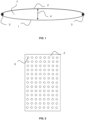
- the vehicle battery or rather the group of battery modules are covered by a battery compartment, preferably shaped as a bowl or a container which is integrated into a crash frame manufactured using an inner active media forming process which provides a deformation space and thus a protection space for impact intrusion.
- a battery compartment preferably shaped as a bowl or a container which is integrated into a crash frame manufactured using an inner active media forming process which provides a deformation space and thus a protection space for impact intrusion.
- at least two metallic sheets are arranged on top of one another whereby different design concepts are possible.
- planar sheets are used.
- the sheets overlap completely. Also linear as well as non-linear overlapping sheets originating from patchwork blanks are possible to apply in the method of the present invention.
- the sheets arranged in the described way are fixed to each other, preferably essentially along the circumference of at least one sheet, and sealed.
- a seal seam welding procedure like a laser beam welding, TIG or plasma welding, GMAW welding or resistance roller seam welding can be used.
- TIG or plasma welding GMAW welding
- resistance roller seam welding can be used.
- different weld shapes and type of joints are possible, depending on the used welding method.
- an edge joint was successfully used during tests as well as a lap joint.
- an edge weld was suitable to create a sealed seam.
- the inner active media forming is preferably a sheet metal hydroforming method according to DIN8584, optionally by using mold-halves as forming tools for the geometry, but more preferably a geometry- and weld seam-depending free forming without any tools to decrease component cost and machine investment.
- the geometry must be influenced by the sheet design, sheet thickness and material strength. Sometimes, the usage of clamping devices is necessary to support the shaping. To influence the resulting component geometry with the sheet design, it is preferable to add welds as limitation elements.
- martensitic steels preferably martensitic stainless steels with a chromium content ⁇ 12%, show a high potential for the method of the present invention.
- the component is manufactured with martensitic steels in annealed delivery condition, followed by an indirect press-hardening process of the component.
- the usage of stainless steel as a consistent material for the whole compartment enables a complete recyclability and processing after component lifetime inside electric arc furnaces to create further products out of stainless steel.
- the same parameters influence the necessary forming pressure.
- the adjusted pressure level varied depending on the used sheet thickness and sheet strength between 40 and 120 bar.
- a further embodiment preferably for the underbody wall or bottom, is to arrange two single components on top of each other to create at least two independent inner spaces used for different functionalities, preferably the outer one as a crash protection and the inner one for thermal management.
- the free inner space with the defined height h i is used by adding auxiliary materials for further or increased functionalities.
- One way to create additional properties is to fill up at least a certain proportion of the deformation space with an insulating material as a further crash and thermal protection for the internally located battery modules. From there, typical auxiliary materials are preferably insulating foams like polyurethane assembly foams used as cavity and hole filling.
- the functionality of the battery compartment manufactured with the method of the present invention is independent from its mounting position within the electric drive vehicle.
- the battery compartment is located over the whole underbody to ensure a maximum battery range, a low centre of gravity and balanced driving dynamics.
- localized constructions like one-side compartments, front or rear-positioning will also work.
- the left and righthand vehicle side (side impact) and the bottom side (underbody slitting) are the preferred sides for using the described battery compartment and its manufacturing method.
- any other vehicle side can become important for safety. It is well known from state-of-the-art vehicles like Hybrid Electric Vehicles that battery compartments could be also positioned behind the rear seat structure or backseat bench.
- the side areas can be optionally protected by structures manufactured according to the method of the present invention, but depending on the vehicle construction just partially.
- Hybrid Electric Vehicles it is possible for Hybrid Electric Vehicles to integrate into the crash frame the battery compartment of the present invention beside and the fuel or hydrogen tank, to have a single crash frame for the whole energy storage.
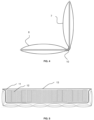
- Fig. 2 illustrates another embodiment of the invention to manufacture a component which can be used for a battery compartment, schematically seen as a view from above to the surface of a sheet 2, whereby limitation elements 5 created by welding are introduced. At these limitation elements 5, the sheets 1, 2 are fixed together. As a result, the limitation elements 5 limit the possible height h i of the space and determine the resulting geometry.
- Fig. 3 illustrates, as a top view, that a component as basically described in Fig. 2 can be manufactured to form a battery compartment with a bottom wall 6 and different side walls 7 by using a bend-forming process at the bending lines 8. The resulting side walls 7 can be welded together at their contact surfaces 9.
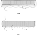
- Fig. 4 shows in a side detail view how a component manufactured according to the invention, e.g. as shown in Fig. 3 , has been bent at a straight angle to form a bottom 6 and a side wall 7, respectively, of a crash frame.
- a component manufactured according to the invention e.g. as shown in Fig. 3
- FIG. 4 shows in a side detail view how a component manufactured according to the invention, e.g. as shown in Fig. 3 , has been bent at a straight angle to form a bottom 6 and a side wall 7, respectively, of a crash frame.
- separate single components as described in figure 1 and 2 can be welded together at 10 to create a resulting battery compartment crash frame with a bottom wall and side walls.
- Fig. 5 illustrates how a component manufactured according to the invention, as shown in e.g. Fig. 3 , has been bent to form a crash frame, into which a battery housing 11 is inserted with installed battery modules 12. The system is covered by a closing plate 13.
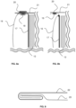
- Fig. 6 illustrates the arrangement of two separate components 14, 15 arranged on top of each other to create at least two independent inner spaces used for different functionalities, preferably the outer one 15 as a crash protection and the inner one 14 for thermal management functions like cooling.
- Fig. 7 illustrates as a side view the use of thinner outer sheets 16 in combination with thicker inner sheets 17 so that mainly the outer sheets are deformed during the inner active media forming process.
- the battery modules 12 in casing 11 can be assembled onto the nearly flat thicker inner sheet 17.
- Fig. 8 a-b illustrate as detail side views of two sealing embodiments at the side walls, providing a closed battery compartment. Both embodiments comprise a thinner outer sheet 16, a thicker inner sheet 17 and the internally located battery modules 12. Further, indentations 18, 19 are provided in the outer surface of the internal active media-formed side walls to create spaces for a sealing layer 20 so that a removable closing plate 21 can be fixed tightly onto the battery compartment.
- the indentation 18 is created by impressing the internal active media-formed side wall from the outside of the thinner outer sheet 16.
- the indentation 19 is created by having a thinner outer sheet 16, the edge of which protrudes outside the thicker inner sheet 17 and is subsequently formed to accommodate the seal material 20.
- Fig. 9 illustrates the fixing of at least one area of the circumferential fixing with a non-welding forming procedure, here folding.
- Two flat metallic sheets 22, 23 arranged on top of one another are bent and folded into each other, creating a sealed seam along their circumference.
Landscapes
- Engineering & Computer Science (AREA)
- Mechanical Engineering (AREA)
- Chemical & Material Sciences (AREA)
- Chemical Kinetics & Catalysis (AREA)
- General Chemical & Material Sciences (AREA)
- Electrochemistry (AREA)
- Fluid Mechanics (AREA)
- Physics & Mathematics (AREA)
- Aviation & Aerospace Engineering (AREA)
- Inorganic Chemistry (AREA)
- Manufacturing & Machinery (AREA)
- Battery Mounting, Suspending (AREA)
- Sealing Battery Cases Or Jackets (AREA)
- Body Structure For Vehicles (AREA)
Claims (13)
- Verfahren zum Herstellen eines Batteriefachs für Elektroantriebsfahrzeuge, das einen Crash-Rahmen mit mindestens einer Komponente umfasst, die einen Raum zwischen zwei Blechen umfasst, wobei das Verfahren dadurch gekennzeichnet ist, dass es die folgenden Schritte umfasst- Bereitstellen von mindestens zwei Metallblechen (1, 2) und Einrichten von mindestens zwei Metallblechen (1, 2) übereinander- Zusammenfügen (3) der mindestens zwei Metallbleche (1, 2) im Wesentlichen an dem Umfang mindestens eines Blechs- Einführen eines Mediums zwischen mindestens zwei Bleche, die zusammengefügt (3) wurden- Anlegen eines Drucks an das Medium, der die Verformung mindestens eines Blechs und das Bilden eines Fachs verursacht, das einen Raum (4) zwischen mindestens zwei Blechen (1, 2) umfasst.
- Verfahren nach Anspruch 1, dadurch gekennzeichnet, dass mindestens zwei Bleche (1, 2) im Wesentlichen planar sind.
- Verfahren nach Anspruch 1 oder 2, dadurch gekennzeichnet, dass mindestens zwei Bleche (1, 2) durch Schweißen oder Falten zusammengefügt (3) werden.
- Verfahren nach einem vorstehenden Anspruch, dadurch gekennzeichnet, dass es weiter den Schritt des Biegens einer Komponente entlang von mindestens zwei Achsen umfasst, um ein Fach zu erzeugen, das mindestens eine Bodenwand (6) und Seitenwände (7) aufweist.
- Verfahren nach einem vorstehenden Anspruch 1-3, dadurch gekennzeichnet, dass es weiter den Schritt des Zusammenfügens einer Vielzahl von Komponenten zum Erzeugen eines Fachs umfasst, das mindestens eine Bodenwand (6) und Seitenwände (7) aufweist.
- Verfahren nach Anspruch 5, dadurch gekennzeichnet, dass das Zusammenfügen (3) der Vielzahl von Komponenten durch Schweißen ausgeführt wird.
- Verfahren nach einem vorstehenden Anspruch, dadurch gekennzeichnet, dass zwei zusammengefügte Metallbleche (1, 2) unterschiedliche Dicken aufweisen.
- Verfahren nach Anspruch 7, dadurch gekennzeichnet, dass sich das Blech (1, 2), das die größere Dicke aufweist, in dem Inneren des Batteriefach befindet.
- Verfahren nach einem vorstehenden Anspruch, dadurch gekennzeichnet, dass mindestens zwei Komponenten aufeinander eingerichtet sind, indem sie mindestens zwei unabhängige Räume (4) zwischen Blechen (1, 2) bereitstellen.
- Verfahren nach Anspruch 9, dadurch gekennzeichnet, dass ein Raum (4) der mindestens zwei unabhängigen Räume zur Verwendung für Wärmemanagement angepasst ist.
- Verfahren nach einem vorstehenden Anspruch, dadurch gekennzeichnet, dass Vertiefungen zum Aufnehmen einer Dichtungsmasse in einer Wand einer Komponente (6, 7) bereitgestellt sind.
- Verfahren nach Anspruch 9, dadurch gekennzeichnet, dass es weiter den Schritt des Auffüllens des geschaffenen Raums aus mindestens zwei unabhängigen Räumen mit einem isolierenden Material als ein weiterer Crash- und Wärmeschutz für die Batteriemodule (12) des darin befindlichen Batteriefachs umfasst.
- Verfahren nach einem vorstehenden Anspruch, dadurch gekennzeichnet, die Metallbleche (1, 2) aus rostfreiem Stahl bestehen.
Priority Applications (11)
| Application Number | Priority Date | Filing Date | Title |
|---|---|---|---|
| EP18199378.3A EP3636364B1 (de) | 2018-10-09 | 2018-10-09 | Verfahren zur herstellung eines crash-rahmens eines batteriefachs für batterieelektrofahrzeuge |
| PL18199378.3T PL3636364T3 (pl) | 2018-10-09 | 2018-10-09 | Sposób wytwarzania ramy zderzeniowej komory akumulatora dla pojazdów akumulatorowych |
| HUE18199378A HUE071435T2 (hu) | 2018-10-09 | 2018-10-09 | Eljárás akkumulátorfoglalat ütközõkeretének gyártására akkumulátoros elektromos jármûvek számára |
| KR1020217008384A KR102917472B1 (ko) | 2018-10-09 | 2019-10-08 | 배터리 전기 차량용 배터리 격실의 충돌 프레임의 제조 방법 |
| PCT/EP2019/077179 WO2020074486A1 (en) | 2018-10-09 | 2019-10-08 | Method for manufacturing a crash frame of a battery compartment for battery electric vehicles |
| MX2021003189A MX2021003189A (es) | 2018-10-09 | 2019-10-08 | Metodo para fabricar un marco contra colision de un compartimiento para baterias para vehiculos electricos a bateria. |
| CN202511404898.3A CN121267040A (zh) | 2018-10-09 | 2019-10-08 | 用于制造用于电池电动车辆的电池仓的碰撞框架的方法 |
| US17/278,021 US11967727B2 (en) | 2018-10-09 | 2019-10-08 | Method for manufacturing a crash frame of a battery compartment for battery electric vehicles |
| CN201980063915.8A CN112770854A (zh) | 2018-10-09 | 2019-10-08 | 用于制造用于电池电动车辆的电池仓的碰撞框架的方法 |
| CA3114690A CA3114690A1 (en) | 2018-10-09 | 2019-10-08 | Method for manufacturing a crash frame of a battery compartment for battery electric vehicles |
| TW108136540A TWI850268B (zh) | 2018-10-09 | 2019-10-09 | 用於電池電動車的電池室的碰撞框架的製造方法 |
Applications Claiming Priority (1)
| Application Number | Priority Date | Filing Date | Title |
|---|---|---|---|
| EP18199378.3A EP3636364B1 (de) | 2018-10-09 | 2018-10-09 | Verfahren zur herstellung eines crash-rahmens eines batteriefachs für batterieelektrofahrzeuge |
Publications (2)
| Publication Number | Publication Date |
|---|---|
| EP3636364A1 EP3636364A1 (de) | 2020-04-15 |
| EP3636364B1 true EP3636364B1 (de) | 2025-04-09 |
Family
ID=63832224
Family Applications (1)
| Application Number | Title | Priority Date | Filing Date |
|---|---|---|---|
| EP18199378.3A Active EP3636364B1 (de) | 2018-10-09 | 2018-10-09 | Verfahren zur herstellung eines crash-rahmens eines batteriefachs für batterieelektrofahrzeuge |
Country Status (10)
| Country | Link |
|---|---|
| US (1) | US11967727B2 (de) |
| EP (1) | EP3636364B1 (de) |
| KR (1) | KR102917472B1 (de) |
| CN (2) | CN121267040A (de) |
| CA (1) | CA3114690A1 (de) |
| HU (1) | HUE071435T2 (de) |
| MX (1) | MX2021003189A (de) |
| PL (1) | PL3636364T3 (de) |
| TW (1) | TWI850268B (de) |
| WO (1) | WO2020074486A1 (de) |
Families Citing this family (16)
| Publication number | Priority date | Publication date | Assignee | Title |
|---|---|---|---|---|
| EP3709387A1 (de) * | 2019-03-11 | 2020-09-16 | voestalpine Metal Forming GmbH | Batteriekasten für eine traktionsbatterie |
| US20220285774A1 (en) * | 2021-03-08 | 2022-09-08 | David Muir | Battery Pack Shield |
| US11394078B1 (en) * | 2021-05-13 | 2022-07-19 | Beta Air, Llc | Battery pack for failure safety |
| DE102021207623A1 (de) | 2021-07-16 | 2023-01-19 | Mahle International Gmbh | Batteriegehäuse zur Aufnahme wenigstens eines Batteriezellenmoduls |
| EP4374453A1 (de) * | 2021-07-23 | 2024-05-29 | Bayerische Motoren Werke Aktiengesellschaft | Antriebsbatterie für ein kraftfahrzeug und kraftfahrzeug mit derartiger antriebsbatterie |
| US12060053B1 (en) | 2021-08-13 | 2024-08-13 | Oshkosh Defense, Llc | Military vehicle with control modes |
| US12083995B1 (en) | 2021-08-13 | 2024-09-10 | Oshkosh Defense, Llc | Power export system for a military vehicle |
| US12130122B1 (en) | 2021-08-13 | 2024-10-29 | Oshkosh Defense, Llc | Military vehicle with battery armor |
| US12583309B1 (en) | 2021-08-13 | 2026-03-24 | Oshkosh Defense, Llc | Hybrid power system for a military vehicle |
| US11383694B1 (en) | 2021-08-13 | 2022-07-12 | Oshkosh Defense, Llc | Electrified military vehicle |
| CN114346046A (zh) * | 2021-12-31 | 2022-04-15 | 潍坊倍力汽车零部件有限公司 | 一种片材内高压管件成型方法 |
| CN116799399B (zh) * | 2022-03-14 | 2025-06-17 | 比亚迪股份有限公司 | 用于电池托盘的边梁、电池托盘、电池包以及车辆 |
| CN116799424B (zh) * | 2022-03-14 | 2025-11-04 | 比亚迪股份有限公司 | 用于电池托盘的边梁、电池托盘、电池包以及车辆 |
| US12555859B2 (en) | 2022-07-07 | 2026-02-17 | Ford Global Technologies, Llc | Battery mounting structure for vehicle |
| CN115436807A (zh) * | 2022-09-01 | 2022-12-06 | 中国第一汽车股份有限公司 | 一种动力电池的测试系统及测试方法 |
| DE102022209210A1 (de) * | 2022-09-05 | 2024-03-07 | Volkswagen Aktiengesellschaft | Verfahren zur Herstellung eines Batteriesystems |
Family Cites Families (61)
| Publication number | Priority date | Publication date | Assignee | Title |
|---|---|---|---|---|
| US2481046A (en) * | 1947-11-13 | 1949-09-06 | Western Engineering Associates | Panel structure |
| US3166831A (en) * | 1962-09-04 | 1965-01-26 | Olin Mathieson | Method of making composite elements |
| US3530029A (en) * | 1968-11-12 | 1970-09-22 | Jerome H Lemelson | Composite sheet forming apparatus and method |
| US5139887A (en) * | 1988-12-27 | 1992-08-18 | Barnes Group, Inc. | Superplastically formed cellular article |
| US5118026A (en) * | 1991-04-05 | 1992-06-02 | Rockwell International Corporation | Method for making titanium aluminide metallic sandwich structures |
| US6251498B1 (en) * | 1993-09-03 | 2001-06-26 | Ibiden Co., Ltd. | Soundproof heat shield member for exhaust manifold |
| US5516600A (en) * | 1994-01-26 | 1996-05-14 | Gnb Battery Technologies Inc. | Temperature-sensitive thermal insulators for lead-acid batteries |
| SE512902C2 (sv) | 1997-11-20 | 2000-06-05 | Ssab Hardtech Ab | Sätt att hydroforma ett ämne |
| DE10103131C2 (de) * | 2001-01-24 | 2002-11-21 | Daimler Chrysler Ag | Verfahren zur Herstellung von Hohlkörpern aus zumindest zwei aufeinanderliegenden Platinen |
| GB0130669D0 (en) * | 2001-12-21 | 2002-02-06 | Cellbond Ltd | Structural component |
| AU2003290853A1 (en) * | 2002-08-02 | 2004-03-11 | Emitec Gesellschaft Fur Emissionstechnologie Mbh | Metallic layer with regions of varying material thickness, method for production of such a metallic layer and honeycomb at least partly made from such metallic layers |
| JP2006122983A (ja) * | 2004-10-29 | 2006-05-18 | Nissan Motor Co Ltd | 液圧成形用予備成形体、液圧成形方法および液圧成形品 |
| DE102006032861A1 (de) * | 2006-07-14 | 2008-01-17 | Emitec Gesellschaft Für Emissionstechnologie Mbh | Erzeugung von Öffnungen in einer Metallfolie sowie damit hergestellte Wabenkörper zur Abgasbehandlung |
| KR100851780B1 (ko) * | 2006-12-27 | 2008-08-13 | 주식회사 성우하이텍 | 차량용 범퍼빔 |
| EP2019193A1 (de) * | 2007-07-26 | 2009-01-28 | Reinz-Dichtungs-Gmbh | Hitzeschild |
| EP2022957B1 (de) * | 2007-07-26 | 2010-04-21 | Reinz-Dichtungs-Gmbh | Verfahren zur Herstellung eines Hitzeschildes |
| US7866531B2 (en) * | 2007-10-31 | 2011-01-11 | Hitachi, Ltd | Multi-sheet structures and method for manufacturing same |
| EP2110189A1 (de) | 2008-04-18 | 2009-10-21 | ETH Zürich | Verfahren zur werkzeuglosen Umformung von Blech |
| WO2010007834A1 (ja) * | 2008-07-17 | 2010-01-21 | トヨタ自動車株式会社 | 緩衝吸音材および吸音構造 |
| JP5608383B2 (ja) * | 2009-02-12 | 2014-10-15 | 豊和繊維工業株式会社 | 自動車用エンジンアンダーカバー |
| DE102010036218A1 (de) | 2010-08-27 | 2012-03-01 | Brandenburgische Technische Universität Cottbus | Schichtelement aus strukturierten wabenförmigen Schichten |
| DE102010051374B4 (de) | 2010-10-20 | 2012-12-06 | Holzner Druckbehälter GmbH | Druckbehälter |
| US20120141851A1 (en) * | 2010-12-06 | 2012-06-07 | Suyu Hou | System and method for enclosing an energy storage device |
| WO2012079156A1 (en) * | 2010-12-17 | 2012-06-21 | Magna International Inc. | Apparatus and method for forming shaped articles from plural sheet metal blanks |
| US20120161472A1 (en) * | 2010-12-22 | 2012-06-28 | Tesla Motors, Inc. | System for Absorbing and Distributing Side Impact Energy Utilizing an Integrated Battery Pack |
| DE102011111229A1 (de) | 2011-08-20 | 2013-02-21 | GEDIA Gebrüder Dingerkus GmbH | Batterieeinhausung für Elektro- und Hybridfahrzeuge |
| TWM422767U (en) * | 2011-08-30 | 2012-02-11 | Silver H Plustechnology Co Ltd | Conductive polymer secondary battery and composite electrode structure thereof |
| ITMI20120148A1 (it) * | 2012-02-03 | 2013-08-04 | Eleda S R L | Pannello fonoassorbente e relativo metodo di realizzazione |
| US20140335368A1 (en) * | 2013-05-13 | 2014-11-13 | Ford Global Technologies, Llc | Method Of Fabricating Roll-Bonded Expanded Load-Bearing Aluminum Laminate Structural Elements For Vehicle |
| JP5900480B2 (ja) * | 2013-05-24 | 2016-04-06 | トヨタ自動車株式会社 | 車両用電池搭載構造 |
| US9052168B1 (en) * | 2013-11-19 | 2015-06-09 | Atieva, Inc. | Electric vehicle undercarriage crumple zone |
| US9054402B1 (en) * | 2013-11-19 | 2015-06-09 | Atieva, Inc. | Electric vehicle battery pack protection system |
| CN203596396U (zh) * | 2013-11-30 | 2014-05-14 | 东莞市金源电池科技有限公司 | 一种防撞击的电动车用锂电池 |
| DE202013009788U1 (de) * | 2013-12-04 | 2014-01-20 | Lisa Dräxlmaier GmbH | Batterie |
| LU92548B1 (de) * | 2014-09-17 | 2016-03-18 | Euro Composites | Wabe, insbesondere verformbare wabe, für leichtbauteile, entsprechendes herstellungsverfahren und sandwichbauteil |
| US9868361B2 (en) * | 2014-12-11 | 2018-01-16 | Ford Global Technologies, Llc | Battery impact absorbing system |
| US9656571B2 (en) | 2015-02-11 | 2017-05-23 | Ford Global Technologies, Llc | Battery enclosure having T-shaped guides on the outer surface for stiffeners and impact absorbing elements |
| US9662997B2 (en) * | 2015-02-11 | 2017-05-30 | Ford Global Technologies, Llc | Method and apparatus for attaching a crushable carbon fiber reinforced polymer structure to the outer surface of a battery enclosure |
| US9931961B2 (en) | 2015-02-11 | 2018-04-03 | Ford Global Technologies, Llc | Battery enclosure surrounded by internally reinforced cylindrical impact absorbing elements |
| JP6520424B2 (ja) | 2015-06-05 | 2019-05-29 | スズキ株式会社 | 車両用バッテリパックの取付け構造 |
| DE102015213860B4 (de) | 2015-07-22 | 2019-06-06 | Volkswagen Aktiengesellschaft | Batterieanordnung in einem elektrisch betriebenen Fahrzeug |
| DE202016103720U1 (de) | 2015-07-30 | 2016-08-31 | Ford Global Technologies, Llc | Gleitender schützender Batteriestützträger |
| US10622687B2 (en) * | 2015-08-10 | 2020-04-14 | Ford Global Technologies, Llc | Battery pack enclosure including integrated fluid channel |
| US10189227B2 (en) * | 2015-10-14 | 2019-01-29 | GM Global Technology Operations LLC | Tailored panel assembly and method of manufacturing the same |
| KR101724926B1 (ko) * | 2015-10-14 | 2017-04-18 | 현대자동차주식회사 | 차량용 리어 플로어 |
| DE102016106021A1 (de) * | 2016-01-21 | 2017-07-27 | Jobst H. KERSPE | Verfahren zur Herstellung eines Batteriegehäuses |
| DE102016108849B3 (de) * | 2016-05-12 | 2017-04-20 | Benteler Automobiltechnik Gmbh | Batteriehalter für ein Kraftfahrzeug |
| US10044006B2 (en) * | 2016-09-07 | 2018-08-07 | Thunder Power New Energy Vehicle Development Company Limited | Offset vehicle crash elements |
| DE102016116729B4 (de) | 2016-09-07 | 2020-12-31 | Kirchhoff Automotive Deutschland Gmbh | Batteriegehäuse für ein elektromotorisch angetriebenes Fahrzeug |
| DE102016120850B4 (de) | 2016-11-02 | 2024-02-22 | Kirchhoff Automotive Deutschland Gmbh | Batteriegehäuse |
| DE102016014191A1 (de) * | 2016-11-29 | 2018-05-30 | Ingenieurgesellschaft Peil | Durch Innendruck-Umformung hergestellter Hohlkörper |
| DE102016125693B4 (de) * | 2016-12-23 | 2021-04-29 | Benteler Automobiltechnik Gmbh | Batterieträger für ein Fahrzeug |
| WO2018127832A1 (en) * | 2017-01-04 | 2018-07-12 | Shape Corp. | Vehicle battery tray structure with nodal modularity |
| DE102017105831C5 (de) * | 2017-03-17 | 2024-02-22 | Benteler Automobiltechnik Gmbh | Batterieträger für ein Fahrzeug |
| CN206938686U (zh) | 2017-03-27 | 2018-01-30 | 宝山钢铁股份有限公司 | 一种前防撞梁吸能盒 |
| KR102256098B1 (ko) * | 2017-04-06 | 2021-06-03 | 주식회사 엘지에너지솔루션 | 루버 핀 형상의 열전도 매개체를 구비한 배터리 팩 |
| WO2018213383A1 (en) * | 2017-05-16 | 2018-11-22 | Shape Corp. | Vehicle battery tray with integrated battery retention and support features |
| DE102017117696B4 (de) * | 2017-08-04 | 2021-04-22 | Deutsches Zentrum für Luft- und Raumfahrt e.V. | Bodensystem für ein Elektrofahrzeug mit einer Kühlstruktur |
| CN207558848U (zh) * | 2017-09-29 | 2018-06-29 | 无锡市华东减震器有限公司 | 一种蓄电池组的冲击防护装置 |
| WO2019071013A1 (en) * | 2017-10-04 | 2019-04-11 | Shape Corp. | BATTERY SUPPORT BOTTOM ASSEMBLY FOR ELECTRIC VEHICLES |
| EP3759761B1 (de) * | 2018-03-01 | 2026-04-08 | Shape Corp. | In fahrzeugbatteriefach integriertes kühlsystem |
-
2018
- 2018-10-09 EP EP18199378.3A patent/EP3636364B1/de active Active
- 2018-10-09 HU HUE18199378A patent/HUE071435T2/hu unknown
- 2018-10-09 PL PL18199378.3T patent/PL3636364T3/pl unknown
-
2019
- 2019-10-08 US US17/278,021 patent/US11967727B2/en active Active
- 2019-10-08 KR KR1020217008384A patent/KR102917472B1/ko active Active
- 2019-10-08 MX MX2021003189A patent/MX2021003189A/es unknown
- 2019-10-08 CN CN202511404898.3A patent/CN121267040A/zh active Pending
- 2019-10-08 CA CA3114690A patent/CA3114690A1/en not_active Abandoned
- 2019-10-08 WO PCT/EP2019/077179 patent/WO2020074486A1/en not_active Ceased
- 2019-10-08 CN CN201980063915.8A patent/CN112770854A/zh active Pending
- 2019-10-09 TW TW108136540A patent/TWI850268B/zh active
Also Published As
| Publication number | Publication date |
|---|---|
| CA3114690A1 (en) | 2020-04-16 |
| KR20210072760A (ko) | 2021-06-17 |
| EP3636364A1 (de) | 2020-04-15 |
| US20210351469A1 (en) | 2021-11-11 |
| CN112770854A (zh) | 2021-05-07 |
| HUE071435T2 (hu) | 2025-09-28 |
| WO2020074486A1 (en) | 2020-04-16 |
| MX2021003189A (es) | 2021-05-27 |
| US11967727B2 (en) | 2024-04-23 |
| TW202100380A (zh) | 2021-01-01 |
| CN121267040A (zh) | 2026-01-06 |
| PL3636364T3 (pl) | 2025-06-02 |
| KR102917472B1 (ko) | 2026-01-23 |
| TWI850268B (zh) | 2024-08-01 |
Similar Documents
| Publication | Publication Date | Title |
|---|---|---|
| US11967727B2 (en) | Method for manufacturing a crash frame of a battery compartment for battery electric vehicles | |
| KR102859533B1 (ko) | 배터리 전기 차량을 위한 열 시스템 | |
| CN109219899B (zh) | 用于车辆电池的壳体以及用于生产这种壳体的方法 | |
| US12181231B2 (en) | Cooling system | |
| JP5552109B2 (ja) | 車載用バッテリートレイおよび車載用バッテリーフレーム | |
| JP2021062710A (ja) | 電動車両用バッテリーケースの製造方法および電動車両用バッテリーケース | |
| US20230014338A1 (en) | Electrical storage battery and vehicle | |
| EP4241911B1 (de) | Verfahren zum herstellen einer geschweissten struktur, geschweisste struktur und batteriegehäuse | |
| JP2021510633A (ja) | 乗用車の曲げ成形された耐荷重構造体 | |
| JP2021063522A (ja) | 高圧タンク搭載構造 | |
| US20230378575A1 (en) | Housing Part, in Particular Lower Housing Part, of an Energy Storage Housing, Energy Storage Housing, and Method for Producing a Housing Part | |
| WO2026068597A1 (en) | Method for laser welding | |
| EP4410579B1 (de) | Seitliches energieabsorptionssystem für fahrzeuge mit elektroantrieb | |
| Olkkonen | Study on manufacturing challenges involved in EV battery welding | |
| US20250141015A1 (en) | Energy Acccumulator Housing, Motor Vehicle, Electric Energy Accumulator, and Series | |
| Lindner | Increased safety for battery electric vehicles by using heat-resistance stainless steels | |
| EP4187701B1 (de) | Seitliche batteriehalterung mit zwei halbzeugen | |
| KR102859257B1 (ko) | 배터리 모듈 케이스의 제조 방법 | |
| US20260024857A1 (en) | Rechargeable energy storage system | |
| CN120824491A (zh) | 边框组件、电池箱体、电池以及用电装置 | |
| TW202201837A (zh) | 冷卻系統 | |
| JP2024165327A (ja) | 電池ケースのケース側壁 |
Legal Events
| Date | Code | Title | Description |
|---|---|---|---|
| PUAI | Public reference made under article 153(3) epc to a published international application that has entered the european phase |
Free format text: ORIGINAL CODE: 0009012 |
|
| STAA | Information on the status of an ep patent application or granted ep patent |
Free format text: STATUS: THE APPLICATION HAS BEEN PUBLISHED |
|
| AK | Designated contracting states |
Kind code of ref document: A1 Designated state(s): AL AT BE BG CH CY CZ DE DK EE ES FI FR GB GR HR HU IE IS IT LI LT LU LV MC MK MT NL NO PL PT RO RS SE SI SK SM TR |
|
| AX | Request for extension of the european patent |
Extension state: BA ME |
|
| STAA | Information on the status of an ep patent application or granted ep patent |
Free format text: STATUS: REQUEST FOR EXAMINATION WAS MADE |
|
| 17P | Request for examination filed |
Effective date: 20201015 |
|
| RBV | Designated contracting states (corrected) |
Designated state(s): AL AT BE BG CH CY CZ DE DK EE ES FI FR GB GR HR HU IE IS IT LI LT LU LV MC MK MT NL NO PL PT RO RS SE SI SK SM TR |
|
| STAA | Information on the status of an ep patent application or granted ep patent |
Free format text: STATUS: EXAMINATION IS IN PROGRESS |
|
| 17Q | First examination report despatched |
Effective date: 20230615 |
|
| REG | Reference to a national code |
Ref country code: DE Ref legal event code: R079 Free format text: PREVIOUS MAIN CLASS: B21D0047020000 Ipc: B21D0026059000 Ref document number: 602018080906 Country of ref document: DE |
|
| GRAP | Despatch of communication of intention to grant a patent |
Free format text: ORIGINAL CODE: EPIDOSNIGR1 |
|
| STAA | Information on the status of an ep patent application or granted ep patent |
Free format text: STATUS: GRANT OF PATENT IS INTENDED |
|
| RIC1 | Information provided on ipc code assigned before grant |
Ipc: B60K 1/04 20190101ALI20241018BHEP Ipc: B60K 1/00 20060101ALI20241018BHEP Ipc: B21D 53/88 20060101ALI20241018BHEP Ipc: B21D 26/021 20110101ALI20241018BHEP Ipc: B21D 47/02 20060101ALI20241018BHEP Ipc: B21D 26/059 20110101AFI20241018BHEP |
|
| INTG | Intention to grant announced |
Effective date: 20241030 |
|
| GRAS | Grant fee paid |
Free format text: ORIGINAL CODE: EPIDOSNIGR3 |
|
| GRAA | (expected) grant |
Free format text: ORIGINAL CODE: 0009210 |
|
| STAA | Information on the status of an ep patent application or granted ep patent |
Free format text: STATUS: THE PATENT HAS BEEN GRANTED |
|
| AK | Designated contracting states |
Kind code of ref document: B1 Designated state(s): AL AT BE BG CH CY CZ DE DK EE ES FI FR GB GR HR HU IE IS IT LI LT LU LV MC MK MT NL NO PL PT RO RS SE SI SK SM TR |
|
| REG | Reference to a national code |
Ref country code: GB Ref legal event code: FG4D |
|
| REG | Reference to a national code |
Ref country code: CH Ref legal event code: EP |
|
| REG | Reference to a national code |
Ref country code: DE Ref legal event code: R096 Ref document number: 602018080906 Country of ref document: DE |
|
| REG | Reference to a national code |
Ref country code: IE Ref legal event code: FG4D |
|
| REG | Reference to a national code |
Ref country code: SE Ref legal event code: TRGR |
|
| REG | Reference to a national code |
Ref country code: NL Ref legal event code: MP Effective date: 20250409 |
|
| PG25 | Lapsed in a contracting state [announced via postgrant information from national office to epo] |
Ref country code: NL Free format text: LAPSE BECAUSE OF FAILURE TO SUBMIT A TRANSLATION OF THE DESCRIPTION OR TO PAY THE FEE WITHIN THE PRESCRIBED TIME-LIMIT Effective date: 20250409 |
|
| REG | Reference to a national code |
Ref country code: AT Ref legal event code: MK05 Ref document number: 1783116 Country of ref document: AT Kind code of ref document: T Effective date: 20250409 |
|
| REG | Reference to a national code |
Ref country code: HU Ref legal event code: AG4A Ref document number: E071435 Country of ref document: HU |
|
| PG25 | Lapsed in a contracting state [announced via postgrant information from national office to epo] |
Ref country code: ES Free format text: LAPSE BECAUSE OF FAILURE TO SUBMIT A TRANSLATION OF THE DESCRIPTION OR TO PAY THE FEE WITHIN THE PRESCRIBED TIME-LIMIT Effective date: 20250409 Ref country code: PT Free format text: LAPSE BECAUSE OF FAILURE TO SUBMIT A TRANSLATION OF THE DESCRIPTION OR TO PAY THE FEE WITHIN THE PRESCRIBED TIME-LIMIT Effective date: 20250811 Ref country code: FI Free format text: LAPSE BECAUSE OF FAILURE TO SUBMIT A TRANSLATION OF THE DESCRIPTION OR TO PAY THE FEE WITHIN THE PRESCRIBED TIME-LIMIT Effective date: 20250409 |
|
| REG | Reference to a national code |
Ref country code: LT Ref legal event code: MG9D |
|
| PG25 | Lapsed in a contracting state [announced via postgrant information from national office to epo] |
Ref country code: GR Free format text: LAPSE BECAUSE OF FAILURE TO SUBMIT A TRANSLATION OF THE DESCRIPTION OR TO PAY THE FEE WITHIN THE PRESCRIBED TIME-LIMIT Effective date: 20250710 Ref country code: NO Free format text: LAPSE BECAUSE OF FAILURE TO SUBMIT A TRANSLATION OF THE DESCRIPTION OR TO PAY THE FEE WITHIN THE PRESCRIBED TIME-LIMIT Effective date: 20250709 |
|
| PGFP | Annual fee paid to national office [announced via postgrant information from national office to epo] |
Ref country code: TR Payment date: 20250930 Year of fee payment: 8 Ref country code: PL Payment date: 20250918 Year of fee payment: 8 |
|
| PG25 | Lapsed in a contracting state [announced via postgrant information from national office to epo] |
Ref country code: BG Free format text: LAPSE BECAUSE OF FAILURE TO SUBMIT A TRANSLATION OF THE DESCRIPTION OR TO PAY THE FEE WITHIN THE PRESCRIBED TIME-LIMIT Effective date: 20250409 |
|
| PG25 | Lapsed in a contracting state [announced via postgrant information from national office to epo] |
Ref country code: HR Free format text: LAPSE BECAUSE OF FAILURE TO SUBMIT A TRANSLATION OF THE DESCRIPTION OR TO PAY THE FEE WITHIN THE PRESCRIBED TIME-LIMIT Effective date: 20250409 |
|
| PG25 | Lapsed in a contracting state [announced via postgrant information from national office to epo] |
Ref country code: AT Free format text: LAPSE BECAUSE OF FAILURE TO SUBMIT A TRANSLATION OF THE DESCRIPTION OR TO PAY THE FEE WITHIN THE PRESCRIBED TIME-LIMIT Effective date: 20250409 |
|
| PG25 | Lapsed in a contracting state [announced via postgrant information from national office to epo] |
Ref country code: RS Free format text: LAPSE BECAUSE OF FAILURE TO SUBMIT A TRANSLATION OF THE DESCRIPTION OR TO PAY THE FEE WITHIN THE PRESCRIBED TIME-LIMIT Effective date: 20250709 |
|
| PG25 | Lapsed in a contracting state [announced via postgrant information from national office to epo] |
Ref country code: IS Free format text: LAPSE BECAUSE OF FAILURE TO SUBMIT A TRANSLATION OF THE DESCRIPTION OR TO PAY THE FEE WITHIN THE PRESCRIBED TIME-LIMIT Effective date: 20250809 |
|
| PG25 | Lapsed in a contracting state [announced via postgrant information from national office to epo] |
Ref country code: LV Free format text: LAPSE BECAUSE OF FAILURE TO SUBMIT A TRANSLATION OF THE DESCRIPTION OR TO PAY THE FEE WITHIN THE PRESCRIBED TIME-LIMIT Effective date: 20250409 |
|
| PGFP | Annual fee paid to national office [announced via postgrant information from national office to epo] |
Ref country code: HU Payment date: 20251027 Year of fee payment: 8 |
|
| PGFP | Annual fee paid to national office [announced via postgrant information from national office to epo] |
Ref country code: DE Payment date: 20251021 Year of fee payment: 8 |
|
| REG | Reference to a national code |
Ref country code: DE Ref legal event code: R097 Ref document number: 602018080906 Country of ref document: DE |
|
| PG25 | Lapsed in a contracting state [announced via postgrant information from national office to epo] |
Ref country code: DK Free format text: LAPSE BECAUSE OF FAILURE TO SUBMIT A TRANSLATION OF THE DESCRIPTION OR TO PAY THE FEE WITHIN THE PRESCRIBED TIME-LIMIT Effective date: 20250409 Ref country code: SM Free format text: LAPSE BECAUSE OF FAILURE TO SUBMIT A TRANSLATION OF THE DESCRIPTION OR TO PAY THE FEE WITHIN THE PRESCRIBED TIME-LIMIT Effective date: 20250409 |
|
| PGFP | Annual fee paid to national office [announced via postgrant information from national office to epo] |
Ref country code: IT Payment date: 20251021 Year of fee payment: 8 |
|
| PGFP | Annual fee paid to national office [announced via postgrant information from national office to epo] |
Ref country code: FR Payment date: 20251030 Year of fee payment: 8 |
|
| PGFP | Annual fee paid to national office [announced via postgrant information from national office to epo] |
Ref country code: SE Payment date: 20251021 Year of fee payment: 8 |
|
| PGFP | Annual fee paid to national office [announced via postgrant information from national office to epo] |
Ref country code: CZ Payment date: 20250930 Year of fee payment: 8 |
|
| PG25 | Lapsed in a contracting state [announced via postgrant information from national office to epo] |
Ref country code: EE Free format text: LAPSE BECAUSE OF FAILURE TO SUBMIT A TRANSLATION OF THE DESCRIPTION OR TO PAY THE FEE WITHIN THE PRESCRIBED TIME-LIMIT Effective date: 20250409 |
|
| PG25 | Lapsed in a contracting state [announced via postgrant information from national office to epo] |
Ref country code: SK Free format text: LAPSE BECAUSE OF FAILURE TO SUBMIT A TRANSLATION OF THE DESCRIPTION OR TO PAY THE FEE WITHIN THE PRESCRIBED TIME-LIMIT Effective date: 20250409 Ref country code: RO Free format text: LAPSE BECAUSE OF FAILURE TO SUBMIT A TRANSLATION OF THE DESCRIPTION OR TO PAY THE FEE WITHIN THE PRESCRIBED TIME-LIMIT Effective date: 20250409 |
|
| PLBE | No opposition filed within time limit |
Free format text: ORIGINAL CODE: 0009261 |
|
| STAA | Information on the status of an ep patent application or granted ep patent |
Free format text: STATUS: NO OPPOSITION FILED WITHIN TIME LIMIT |
|
| REG | Reference to a national code |
Ref country code: CH Ref legal event code: L10 Free format text: ST27 STATUS EVENT CODE: U-0-0-L10-L00 (AS PROVIDED BY THE NATIONAL OFFICE) Effective date: 20260218 |
|
| 26N | No opposition filed |
Effective date: 20260112 |