EP3634793B1 - Transportkühlsystem - Google Patents
Transportkühlsystem Download PDFInfo
- Publication number
- EP3634793B1 EP3634793B1 EP18735452.7A EP18735452A EP3634793B1 EP 3634793 B1 EP3634793 B1 EP 3634793B1 EP 18735452 A EP18735452 A EP 18735452A EP 3634793 B1 EP3634793 B1 EP 3634793B1
- Authority
- EP
- European Patent Office
- Prior art keywords
- transport refrigeration
- energy storage
- refrigerant
- heat exchanger
- storage device
- Prior art date
- Legal status (The legal status is an assumption and is not a legal conclusion. Google has not performed a legal analysis and makes no representation as to the accuracy of the status listed.)
- Active
Links
- 238000005057 refrigeration Methods 0.000 title claims description 72
- 239000003507 refrigerant Substances 0.000 claims description 70
- 238000004146 energy storage Methods 0.000 claims description 52
- 230000037361 pathway Effects 0.000 claims description 7
- 238000004891 communication Methods 0.000 claims description 5
- 238000001816 cooling Methods 0.000 claims description 5
- 239000007788 liquid Substances 0.000 description 8
- CURLTUGMZLYLDI-UHFFFAOYSA-N Carbon dioxide Chemical compound O=C=O CURLTUGMZLYLDI-UHFFFAOYSA-N 0.000 description 6
- 239000007789 gas Substances 0.000 description 6
- QGZKDVFQNNGYKY-UHFFFAOYSA-N Ammonia Chemical compound N QGZKDVFQNNGYKY-UHFFFAOYSA-N 0.000 description 4
- ATUOYWHBWRKTHZ-UHFFFAOYSA-N Propane Chemical compound CCC ATUOYWHBWRKTHZ-UHFFFAOYSA-N 0.000 description 4
- 238000002485 combustion reaction Methods 0.000 description 4
- 229910002092 carbon dioxide Inorganic materials 0.000 description 3
- 239000001569 carbon dioxide Substances 0.000 description 3
- 230000006835 compression Effects 0.000 description 3
- 238000007906 compression Methods 0.000 description 3
- 229910021529 ammonia Inorganic materials 0.000 description 2
- 230000007613 environmental effect Effects 0.000 description 2
- 239000000446 fuel Substances 0.000 description 2
- 239000000463 material Substances 0.000 description 2
- VNWKTOKETHGBQD-UHFFFAOYSA-N methane Chemical compound C VNWKTOKETHGBQD-UHFFFAOYSA-N 0.000 description 2
- 239000001294 propane Substances 0.000 description 2
- RYGMFSIKBFXOCR-UHFFFAOYSA-N Copper Chemical compound [Cu] RYGMFSIKBFXOCR-UHFFFAOYSA-N 0.000 description 1
- XAGFODPZIPBFFR-UHFFFAOYSA-N aluminium Chemical compound [Al] XAGFODPZIPBFFR-UHFFFAOYSA-N 0.000 description 1
- 229910052782 aluminium Inorganic materials 0.000 description 1
- 230000001276 controlling effect Effects 0.000 description 1
- 229910052802 copper Inorganic materials 0.000 description 1
- 239000010949 copper Substances 0.000 description 1
- 230000008878 coupling Effects 0.000 description 1
- 238000010168 coupling process Methods 0.000 description 1
- 238000005859 coupling reaction Methods 0.000 description 1
- 238000005516 engineering process Methods 0.000 description 1
- 238000012986 modification Methods 0.000 description 1
- 230000004048 modification Effects 0.000 description 1
- 239000003345 natural gas Substances 0.000 description 1
- 230000001105 regulatory effect Effects 0.000 description 1
- 230000019491 signal transduction Effects 0.000 description 1
- 238000011144 upstream manufacturing Methods 0.000 description 1
- 238000010792 warming Methods 0.000 description 1
Images

Classifications
-
- B—PERFORMING OPERATIONS; TRANSPORTING
- B60—VEHICLES IN GENERAL
- B60H—ARRANGEMENTS OF HEATING, COOLING, VENTILATING OR OTHER AIR-TREATING DEVICES SPECIALLY ADAPTED FOR PASSENGER OR GOODS SPACES OF VEHICLES
- B60H1/00—Heating, cooling or ventilating [HVAC] devices
- B60H1/00271—HVAC devices specially adapted for particular vehicle parts or components and being connected to the vehicle HVAC unit
- B60H1/00278—HVAC devices specially adapted for particular vehicle parts or components and being connected to the vehicle HVAC unit for the battery
-
- B—PERFORMING OPERATIONS; TRANSPORTING
- B60—VEHICLES IN GENERAL
- B60H—ARRANGEMENTS OF HEATING, COOLING, VENTILATING OR OTHER AIR-TREATING DEVICES SPECIALLY ADAPTED FOR PASSENGER OR GOODS SPACES OF VEHICLES
- B60H1/00—Heating, cooling or ventilating [HVAC] devices
- B60H1/00007—Combined heating, ventilating, or cooling devices
- B60H1/00014—Combined heating, ventilating, or cooling devices for load cargos on load transporting vehicles
-
- B—PERFORMING OPERATIONS; TRANSPORTING
- B60—VEHICLES IN GENERAL
- B60H—ARRANGEMENTS OF HEATING, COOLING, VENTILATING OR OTHER AIR-TREATING DEVICES SPECIALLY ADAPTED FOR PASSENGER OR GOODS SPACES OF VEHICLES
- B60H1/00—Heating, cooling or ventilating [HVAC] devices
- B60H1/00357—Air-conditioning arrangements specially adapted for particular vehicles
- B60H1/00378—Air-conditioning arrangements specially adapted for particular vehicles for tractor or load vehicle cabins
-
- B—PERFORMING OPERATIONS; TRANSPORTING
- B60—VEHICLES IN GENERAL
- B60H—ARRANGEMENTS OF HEATING, COOLING, VENTILATING OR OTHER AIR-TREATING DEVICES SPECIALLY ADAPTED FOR PASSENGER OR GOODS SPACES OF VEHICLES
- B60H1/00—Heating, cooling or ventilating [HVAC] devices
- B60H1/00421—Driving arrangements for parts of a vehicle air-conditioning
- B60H1/00428—Driving arrangements for parts of a vehicle air-conditioning electric
-
- B—PERFORMING OPERATIONS; TRANSPORTING
- B60—VEHICLES IN GENERAL
- B60H—ARRANGEMENTS OF HEATING, COOLING, VENTILATING OR OTHER AIR-TREATING DEVICES SPECIALLY ADAPTED FOR PASSENGER OR GOODS SPACES OF VEHICLES
- B60H1/00—Heating, cooling or ventilating [HVAC] devices
- B60H1/00642—Control systems or circuits; Control members or indication devices for heating, cooling or ventilating devices
- B60H1/00814—Control systems or circuits characterised by their output, for controlling particular components of the heating, cooling or ventilating installation
- B60H1/00878—Control systems or circuits characterised by their output, for controlling particular components of the heating, cooling or ventilating installation the components being temperature regulating devices
- B60H1/00885—Controlling the flow of heating or cooling liquid, e.g. valves or pumps
-
- B—PERFORMING OPERATIONS; TRANSPORTING
- B60—VEHICLES IN GENERAL
- B60H—ARRANGEMENTS OF HEATING, COOLING, VENTILATING OR OTHER AIR-TREATING DEVICES SPECIALLY ADAPTED FOR PASSENGER OR GOODS SPACES OF VEHICLES
- B60H1/00—Heating, cooling or ventilating [HVAC] devices
- B60H1/32—Cooling devices
- B60H1/3204—Cooling devices using compression
- B60H1/3222—Cooling devices using compression characterised by the compressor driving arrangements, e.g. clutches, transmissions or multiple drives
-
- B—PERFORMING OPERATIONS; TRANSPORTING
- B60—VEHICLES IN GENERAL
- B60H—ARRANGEMENTS OF HEATING, COOLING, VENTILATING OR OTHER AIR-TREATING DEVICES SPECIALLY ADAPTED FOR PASSENGER OR GOODS SPACES OF VEHICLES
- B60H1/00—Heating, cooling or ventilating [HVAC] devices
- B60H1/32—Cooling devices
- B60H1/3204—Cooling devices using compression
- B60H1/3227—Cooling devices using compression characterised by the arrangement or the type of heat exchanger, e.g. condenser, evaporator
-
- B—PERFORMING OPERATIONS; TRANSPORTING
- B60—VEHICLES IN GENERAL
- B60H—ARRANGEMENTS OF HEATING, COOLING, VENTILATING OR OTHER AIR-TREATING DEVICES SPECIALLY ADAPTED FOR PASSENGER OR GOODS SPACES OF VEHICLES
- B60H1/00—Heating, cooling or ventilating [HVAC] devices
- B60H1/32—Cooling devices
- B60H1/3204—Cooling devices using compression
- B60H1/3232—Cooling devices using compression particularly adapted for load transporting vehicles
-
- F—MECHANICAL ENGINEERING; LIGHTING; HEATING; WEAPONS; BLASTING
- F25—REFRIGERATION OR COOLING; COMBINED HEATING AND REFRIGERATION SYSTEMS; HEAT PUMP SYSTEMS; MANUFACTURE OR STORAGE OF ICE; LIQUEFACTION SOLIDIFICATION OF GASES
- F25D—REFRIGERATORS; COLD ROOMS; ICE-BOXES; COOLING OR FREEZING APPARATUS NOT OTHERWISE PROVIDED FOR
- F25D11/00—Self-contained movable devices, e.g. domestic refrigerators
- F25D11/003—Transport containers
-
- B—PERFORMING OPERATIONS; TRANSPORTING
- B60—VEHICLES IN GENERAL
- B60H—ARRANGEMENTS OF HEATING, COOLING, VENTILATING OR OTHER AIR-TREATING DEVICES SPECIALLY ADAPTED FOR PASSENGER OR GOODS SPACES OF VEHICLES
- B60H1/00—Heating, cooling or ventilating [HVAC] devices
- B60H1/00271—HVAC devices specially adapted for particular vehicle parts or components and being connected to the vehicle HVAC unit
- B60H2001/00307—Component temperature regulation using a liquid flow
-
- B—PERFORMING OPERATIONS; TRANSPORTING
- B60—VEHICLES IN GENERAL
- B60H—ARRANGEMENTS OF HEATING, COOLING, VENTILATING OR OTHER AIR-TREATING DEVICES SPECIALLY ADAPTED FOR PASSENGER OR GOODS SPACES OF VEHICLES
- B60H1/00—Heating, cooling or ventilating [HVAC] devices
- B60H1/32—Cooling devices
- B60H2001/3286—Constructional features
- B60H2001/3292—Compressor drive is electric only
-
- Y—GENERAL TAGGING OF NEW TECHNOLOGICAL DEVELOPMENTS; GENERAL TAGGING OF CROSS-SECTIONAL TECHNOLOGIES SPANNING OVER SEVERAL SECTIONS OF THE IPC; TECHNICAL SUBJECTS COVERED BY FORMER USPC CROSS-REFERENCE ART COLLECTIONS [XRACs] AND DIGESTS
- Y02—TECHNOLOGIES OR APPLICATIONS FOR MITIGATION OR ADAPTATION AGAINST CLIMATE CHANGE
- Y02E—REDUCTION OF GREENHOUSE GAS [GHG] EMISSIONS, RELATED TO ENERGY GENERATION, TRANSMISSION OR DISTRIBUTION
- Y02E60/00—Enabling technologies; Technologies with a potential or indirect contribution to GHG emissions mitigation
- Y02E60/10—Energy storage using batteries
Definitions
- the present invention relates to a transport refrigeration system and, more particularly, to an energy storage device of the transport refrigeration system.
- Refrigeration systems typically include a compressor, a condenser, an expansion valve, and an evaporator serially connected by refrigerant lines in a closed refrigerant circuit in accord with known refrigerant vapor compression cycles.
- a power unit such as a combustion engine, drives the compressor of the refrigeration unit, and may be diesel powered, natural gas powered, or other type of engine.
- the compressor is driven by the engine shaft either through a belt drive or by a mechanical shaft-to-shaft link.
- the engine of the refrigeration unit drives a generator that generates electrical power, which inturn drives the compressor.
- WO 2016/040435 A1 discloses a system for refrigerating a container used in intermodal freight transport using a hybrid refrigeration system coupling an electrical compressor and/or a heat pump, with a battery, and ultimately with cold energy storage technology.
- a transport refrigeration system includes a transport refrigeration unit constructed and arranged to cool a container; an energy storage device constructed and arranged to provide energy for operating the transport refrigeration unit; at least one electrical pathway operatively coupled between the transport refrigeration unit and the energy storage device for supplying at least electrical energy to the transport refrigeration unit; characterized by a supply refrigerant tube for flowing a refrigerant from the transport refrigeration unit to the energy storage device; and a return refrigerant tube for flowing the refrigerant from the energy storage device to the transport refrigeration unit.
- the energy storage device is remotely located from the transport refrigeration unit.
- the energy storage device is remotely located from the transport refrigeration unit.
- the container is a trailer
- the transport refrigeration unit is mounted to a front wall of the trailer
- the energy storage device is mounted beneath a bottom wall of the trailer.
- the energy storage device includes an energy storage unit and an evaporator subsystem in communication with the supply and return refrigerant tubes for cooling the energy storage unit.
- the energy storage device includes an evaporator heat exchanger constructed and arranged to receive the refrigerant from the supply refrigerant tube and expel the refrigerant into the return refrigerant line.
- the energy storage device includes an evaporator fan assembly constructed and arranged to blow air through the evaporator heat exchanger.
- the energy storage device includes a casing that encloses the energy storage unit, and the evaporator heat exchanger is a tube in contact with and extending about the casing for conductive heat transfer.
- the transport refrigeration unit includes a compressor constructed and arranged to compress the refrigerant, a compressor motor configured to drive the compressor, a condenser heat exchanger operatively couple to the compressor, a condenser fan configured to provide air flow over the condenser heat exchanger, a condenser fan motor for driving the condenser fan, an evaporator heat exchanger operatively coupled to the compressor, an evaporator fan configured to provide air flow over the evaporator heat exchanger, and an evaporator fan motor for driving the evaporator fan.
- the supply refrigerant tube communicates with the transport refrigeration unit between the condenser heat exchanger and the evaporator heat exchanger.
- the transport refrigeration system includes a control valve adapted to control the flow of refrigerant and disposed between a receiver of the transport refrigeration unit and the condenser heat exchanger, wherein the control valve communicates with the supply refrigerant tube.
- the return refrigerant tube communicates with the transport refrigeration unit between the evaporator heat exchanger and the compressor.
- the energy storage device is constructed and arranged to provide electrical energy to at least one of the compressor motor, the condenser fan motor, and the evaporator fan motor.
- the energy storage unit is at least one battery.
- a transport refrigeration system according to the first aspect and a remote energy storage device for providing electrical energy to a refrigeration unit
- the remote energy storage device includes a casing; a battery disposed in the casing; and an evaporator subsystem including a heat exchanger constructed and arranged to receive condensed refrigerant from the refrigeration unit to cool the battery.
- the tractor trailer system 20 may include a tractor or truck 22, a trailer 24 and a transport refrigeration system 26.
- the tractor 22 may include an operator's compartment or cab 28 and a combustion engine 30 is part of the powertrain or drive system of the tractor 22.
- the trailer 24 may be coupled to the tractor 22 and is thus pulled or propelled to desired destinations.
- the trailer may include a top wall 32, a bottom wall 34 opposed to and space from the top wall 32, two side walls 36 spaced from and opposed to one-another, and opposing front and rear walls 38, 40 with the front wall 38 being closest to the tractor 22.
- the trailer 24 may further include doors (not shown) at the rear wall 40, or any other wall.
- the walls 32, 34, 36, 38, 40 together define the boundaries of a cargo compartment 42. It is further contemplated and understood that the cargo compartment 42 may also be divided into two or more smaller compartments for different cargo temperature requirements.
- the trailer 24 is generally constructed to store a cargo (not shown) in the compartment 42.
- the transport refrigeration system 26 may be generally integrated into the trailer 24, and may include a transport refrigeration unit (TRU) 44 and an energy storage device (ESD) 46.
- TRU 44 may be mounted to the front wall 38, and the ESD 46 may generally be mounted remotely.
- the ESD 46 may be secured to, and mounted beneath, the bottom wall 34.
- the cargo is maintained at a desired temperature by cooling of the compartment 42 via the TRU 44 that circulates airflow into and through the cargo compartment 42 of the trailer 24.
- the transport refrigeration system 26 may be applied to any transport container, and not necessarily those used in tractor trailer systems.
- the transport container may be a part of the trailer 24 and constructed to be removed from a framework and wheels (not shown) of the trailer 24 for alternative shipping means (e.g., marine, rail, flight, and others).
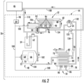
- the components of the TRU 44 may include a compressor assembly 48, a condenser assembly 50, an evaporator assembly 52, a receiver 54, a filter dryer 56, a refrigerant-to-refrigerant heat exchanger 58, an accumulator 59, a thermostatic expansion valve 60, a suction modulation valve 62, and a controller 64.
- the controller 64 may be locally located with the TRU 44, and may include a computer-based processor (e.g., microprocessor) and an electronic storage medium that may be computer readable and writeable.
- the compressor assembly 48 may include a compressor 66 and an electric compressor motor 68 for driving the compressor. The compressor 66 may also be driven by alternative means.
- the compressor 66 and the compressor motor 68 may be linked via an interconnecting drive shaft 70.
- the compressor 66, the compressor motor 68 and the drive shaft 70 may be sealed within a common housing 72.
- the compressor motor 68 may be positioned outside of the compressor housing 72, with the interconnecting drive shaft 70 passing through a shaft seal (not shown) supported by the compressor housing 72.
- the compressor 66 may be a single compressor.
- the single compressor may be a two-stage compressor, a scroll-type compressor or other type of compressor adapted to compress, for example, natural refrigerants.
- the natural refrigerant may be CO2, propane, ammonia, or any other natural refrigerant that may include a global-warming potential (GWP) of about one (1).
- GWP global-warming potential
- the condenser assembly 50 may include a condenser heat exchanger 74, a subcooler heat exchanger 76, and a condenser fan assembly 78 for flowing air through the heat exchangers 74, 76.
- the heat exchangers 74, 76 may include respective tubes 80, 82.
- the fan assembly 78 may include at least one fan 84 and at least one electric fan motor 86 for driving the at least one fan 84 (i.e., two illustrated) that induces the flow of air about the tubes 80, 82 of the respective heat exchangers 74, 76. It is contemplated that alternative means, other than the condenser fan assembly 78, may be applied to induce the flow of air through the condenser heat exchangers 74, 76. It is further contemplated that alternative means, other than the use of the electric fan motor 86, may be applied to drive the condenser fan 84.
- the evaporator assembly 52 may include an evaporator heat exchanger 88 and an evaporator fan assembly 90 for flowing air through the heat exchanger 88.
- the heat exchanger 88 may include tube(s) 92.
- the fan assembly 90 may include at least one fan 94 and at least one electric fan motor 96 for driving the at least one fan 94 (i.e., three illustrated) that supplies a flow of air about the tubes 92 of the heat exchanger 88. It is contemplated that alternative means, other than the evaporator fan assembly 90, may be applied to induce the flow of air through the evaporator heat exchanger 88. It is further contemplated that alternative means, other than the use of the electric fan motor 96, may be applied to drive the evaporator fan 94.
- the transport refrigeration system 26 may further include an electrical pathway or bus 98 that may extend between the ESD 46 and the controller 64.
- the TRU 44 may further include an electrical pathway or bus 100 that may extend between the controller 64 and the various electrical loads including the compressor motor 68, the condenser fan motor(s) 86, the evaporator fan motors 96, and other loads.
- the pathways 98, 100 may include both control pathways that may be wireless or hardwired, and power supply wiring.
- an energy supply pathway may be direct wired from the ESD 46 to the electric motors 68, 86, 96.
- Operation of the TRU 44 may be best understood by starting at the compressor 66 of the compressor assembly 48, where the suction gas (e.g., natural refrigerant) enters the compressor 66 at a suction port 102 and is compressed to a higher temperature and pressure.
- the refrigerant gas is emitted from the compressor 66 at an outlet port 104, and may then flow into the tube(s) 80 of the condenser heat exchanger 74.
- the air flow across the condenser heat exchanger 74 is facilitated by the condenser fan assembly 78.
- the gas within the tubes 80 condenses to a high temperature liquid at a high pressure, and flows to the receiver 54 that provides storage for excess liquid refrigerant during low temperature operation.
- the liquid refrigerant may pass through the subcooler heat exchanger 76 of the condenser assembly 50, through the filter-dryer 56 that keeps the refrigerant clean and dry, then to the refrigerant-to-refrigerant heat exchanger 58 that increases the refrigerant subcooling, and finally to the thermostatic expansion valve 60.
- the liquid refrigerant passes through the orifices of the expansion valve 60, some of the liquid vaporizes into a gas (i.e., flash gas).
- a gas i.e., flash gas
- Return air from the refrigerated space i.e., cargo compartment 42
- the tubes 92 and fins (not shown) of the evaporator heat exchanger 88 As the refrigerant flows through the tubes 92, the remaining liquid refrigerant absorbs heat from the return air, and in so doing, the remaining liquid refrigerant is vaporized.
- the air flow across the evaporator heat exchanger 88 is facilitated by the evaporator fan assembly 90.
- the refrigerant in vapor form, may then flow to the accumulator 59 that may be used to prevent the entry of any liquid refrigerant into the compressor 66.
- the refrigerant, in vapor form, is drawn from the upper part of the suction accumulator through the suction modulation valve 62, and back to the compressor 66.
- a thermostatic expansion valve bulb sensor 106 may be located proximate to an outlet of the evaporator tube 92.
- the bulb sensor 106 is intended to control the thermostatic expansion valve 60, thereby controlling refrigerant superheat at the outlet of the evaporator tube 92. It is further contemplated and understood that the above generally describes a single stage vapor compression system that may be used for many different refrigerants including natural refrigerants such as propane and ammonia. Other refrigerant systems may also be applied that use carbon dioxide (CO2) refrigerant, and that may be a two-stage vapor compression system.
- CO2 carbon dioxide
- the transport refrigeration system 26 may further include supply and return refrigerant tubes 108, 110 each extending between the ESD 46 and the TRU 44.
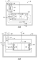
- the ESD 46 may include at least one energy storage unit 112 (e.g., battery or bank of batteries), an evaporator subsystem 114, a generally enclosed outer housing 116, and a generally enclosed casing 118. One, or both, of the housing 116 and the casing 118 may be thermally insulated.
- the batteries 112 may be located in the casing 118.
- the evaporator subsystem 114 and the casing 118 with the batteries 112 may be located in the housing 116.
- the battery cooling, or evaporator, subsystem 114 may include a fan assembly 120, a heat exchanger 122, a temperature sensor 124 that may be located, or exposed to temperatures, in the casing 118, an air duct 126 for the recirculation of air (see arrow 128 in FIG. 3 ), a refrigerant-to-refrigerant heat exchanger 129, a thermostatic expansion valve 131, and a thermostatic expansion valve bulb sensor 133.
- the fan assembly 120 is adapted to flow air across the heat exchanger 122 as, for example, commanded by the controller 64 via signal pathway 98 and dictated by temperature data read from the temperature sensor 124.
- the air may flow through an inlet opening 130 communicating through the casing 118, may circulate about the batteries 112, flow out of the casing 118 via an outlet opening 132. From the outlet opening 132, the air 128 may flow through the air duct 126, and back to the fan assembly 120 for recirculation.
- the batteries may thus be cooled primarily via thermal convection.
- the duct 126 may be an integral part of one or both of the housing 116 and the casing 118.
- the duct walls may be portions of the housing 116 and the casing 118.
- the supply refrigerant tube 108 may extend between, and may be in communication with, an outlet of the filter drier 56 and an inlet of the refrigerant-to-refrigerant heat exchanger 129 adapted to increase refrigerant subcooling prior to the evaporator heat exchanger 122 of the evaporator subsystem 114. More specifically, the evaporator subsystem 114 may further include a control valve 135 juxtaposed in a refrigerant line 134 extending between the refrigerant-to-refrigerant heat exchanger 58 and the filter drier 56. The supply refrigerant tube 108 may be attached to the control valve 130 for controlled communication with the refrigerant line 134.
- the control valve 130 may be controlled by the controller 64 permitting refrigerant flow through the supply refrigerant tube 108 when cooling of the batteries 112 is needed.
- the return refrigerant tube 110 may extend between, and is in communication with, an outlet of the refrigerant-to-refrigerant heat exchanger 129 of the evaporator subsystem 114 and an inlet of the accumulator 59 (i.e., upstream of the accumulator 59 and downstream of the evaporator tube 92).
- the ESD 46 may include any variety of other sensors adapted to communicate with the controller 46, or an independent controller. For example, one sensor may measure the amount of energy remaining in the batteries 112.
- the transport refrigeration system 26 may be powered solely by the ESD 46 with all of the loads (i.e., motors, controller, valves, etc.) being direct current (DC) loads.
- the system 26 may include a generator that may be driven by, for example, a combustion engine (not shown).
- some of the loads may run on alternating current (AC) power and others on DC power.
- the energy storage units 112 may be fuel cells or other means capable of storing electrical energy.
- An ESD 46' may include at least one energy storage unit 112', an evaporator subsystem 114', a generally enclosed outer housing 116', and a generally enclosed casing 118'.
- the housing 116' may be thermally insulated, and the casing 118' may be thermally conductive.
- the energy storage unit 112' may be located in the casing 118', or the casing may be an integral part of the energy storage unit 112' (e.g., an outer wall of the energy storage unit).
- the evaporator subsystem 114' and the casing 118' with the energy storage unit 112' may be located in the housing 116'.
- the evaporator subsystem 114' may not include a fan assembly and may not require an air duct. Instead, the evaporator subsystem 114' may rely on thermal conduction to cool the energy storage unit 112'. More specifically, the evaporator subsystem 114', may include refrigerant tube(s) 122' as a heat exchanger that is in continuous contact with, and generally wraps about, the casing 118'. Alternatively, the flow tubes 122' may be machined directly into the casing 118'.
- the casing 118' may be made of any material with a high thermal conductivity coefficient, and may be made, at least in-part, of copper or aluminum.
- Benefits of the present invention when compared to more traditional systems include lower fuel consumption, and a refrigeration unit that may emit less noise and may be lighter in weight. Furthermore, the present invention includes an energy storage device that may be conveniently and efficiently recharged to meet the power demands of the refrigeration unit while meeting combustion engine power and emission requirements that may be enforced by regulatory/government agencies. Yet further, the present invention provides a means to cool energy storage units thus extending the life of the units.
Landscapes
- Engineering & Computer Science (AREA)
- Physics & Mathematics (AREA)
- Mechanical Engineering (AREA)
- Thermal Sciences (AREA)
- Chemical & Material Sciences (AREA)
- Combustion & Propulsion (AREA)
- General Engineering & Computer Science (AREA)
- Devices That Are Associated With Refrigeration Equipment (AREA)
Claims (15)
- Transportkühlsystem (26), umfassend:eine Transportkühleinheit (44), die konstruiert und angeordnet ist, um einen Behälter zu kühlen;eine Energiespeichervorrichtung (46), die konstruiert und angeordnet ist, um Energie zum Betreiben der Transportkühleinheit bereitzustellen;mindestens einen elektrischen Pfad (100), der zwischen der Transportkühleinheit und der Energiespeichereinrichtung wirkgekoppelt ist, um mindestens elektrische Energie zu der Transportkühleinheit zuzuführen; und gekennzeichnet durchein Versorgungskältemittelrohr (108), um ein Kältemittel von der Transportkühleinheit zu der Energiespeichervorrichtung strömen zu lassen; undein Rückführungskältemittelrohr (110), um das Kältemittels von der Energiespeichervorrichtung zu der Transportkühleinheit strömen zu lassen.
- Transportkühlsystem (26) nach Anspruch 1, wobei die Energiespeichervorrichtung (46) durch die Transportkühleinheit (44) steuerbar gekühlt wird.
- Transportkühlsystem (26) nach Anspruch 1, wobei sich die Energiespeichervorrichtung (46) entfernt von der Transportkühleinheit (44) befindet.
- Transportkühlsystem (26) nach Anspruch 1, wobei der Behälter ein Anhänger (24) ist, die Transportkühleinheit (44) an einer Vorderwand (38) des Anhängers montiert ist und die Energiespeichervorrichtung (46) unterhalb einer Bodenwand (34) des Anhängers montiert ist.
- Transportkühlsystem (26) nach Anspruch 1, wobei die Energiespeichervorrichtung (46) eine Energiespeichereinheit (112) und ein Verdampferteilsystem (114) in Verbindung mit dem Versorgungskältemittelrohr (108) und dem Rückführungskältemittelrohr (110) zum Kühlen der Energiespeichereinheit beinhaltet.
- Transportkühlsystem (26) nach Anspruch 5, wobei die Energiespeichervorrichtung (46) einen Verdampferwärmetauscher (122) beinhaltet, der konstruiert und angeordnet ist, um das Kältemittel aus dem Versorgungskältemittelrohr (108) aufzunehmen und das Kältemittel in die Rückführungskältemittelleitung (110) auszustoßen.
- Transportkühlsystem (26) nach Anspruch 6, wobei die Energiespeichervorrichtung (46) eine Verdampfergebläsebaugruppe (90) beinhaltet, die konstruiert und angeordnet ist, um Luft durch den Verdampferwärmetauscher (122) zu blasen.
- Transportkühlsystem (26) nach Anspruch 6, wobei die Energiespeichervorrichtung (46) ein Gehäuse (118) beinhaltet, das die Energiespeichereinheit umschließt, und der Verdampferwärmetauscher (122) ein Rohr ist, das für eine leitende Wärmeübertragung in Kontakt mit dem Gehäuse steht und sich um dieses erstreckt.
- Transportkühlsystem (26) nach Anspruch 1, wobei die Transportkühleinheit (44) einen Kompressor (66), der konstruiert und angeordnet ist, um das Kältemittel zu komprimieren, einen Kompressormotor (68), der dazu konfiguriert ist, den Kompressor anzutreiben, einen Kondensatorwärmetauscher (74, 76), der mit dem Kompressor wirkgekoppelt ist, ein Kondensatorgebläse (84), das dazu konfiguriert ist, einen Luftstrom über den Kondensatorwärmetauscher bereitzustellen, einen Kondensatorgebläsemotor (86) zum Antreiben des Kondensatorgebläses, einen Verdampferwärmetauscher (88), der mit dem Kompressor wirkgekoppelt ist, ein Verdampfergebläse (94), das dazu konfiguriert ist, einen Luftstrom über den Verdampferwärmetauscher bereitzustellen, und einen Verdampfergebläsemotor (96) zum Antreiben des Verdampfergebläses beinhaltet.
- Transportkühlsystem (26) nach Anspruch 9, wobei das Versorgungskältemittelrohr (108) mit der Transportkühleinheit (44) zwischen dem Kondensatorwärmetauscher (74, 76) und dem Verdampferwärmetauscher (88) in Verbindung steht.
- Transportkühlsystem (26) nach Anspruch 10, ferner umfassend: ein Steuerventil (135), das dazu eingerichtet ist, den Kältemittelstrom zu steuern, und das zwischen einer Aufnahme (54) der Transportkühleinheit (44) und dem Kondensatorwärmetauscher (74, 76) angeordnet ist, wobei das Steuerventil mit dem Versorgungskältemittelrohr (108) in Verbindung steht.
- Transportkühlsystem (26) nach Anspruch 10, wobei das Rückführungskältemittelrohr (110) mit der Transportkühleinheit (44) zwischen dem Verdampferwärmetauscher (88) und dem Kompressor (66) in Verbindung steht.
- Transportkühlsystem (26) nach Anspruch 9, wobei die Energiespeichervorrichtung (46) konstruiert und angeordnet ist, um zumindest einem von dem Kompressormotor (68), dem Kondensatorgebläsemotor (86) und dem Verdampfergebläsemotor (96) elektrische Energie bereitzustellen.
- Transportkühlsystem (26) nach Anspruch 5, wobei die Energiespeichereinheit (121) mindestens eine Batterie ist.
- Transportkühlsystem nach einem der vorhergehenden Ansprüche und eine entfernte Energiespeichervorrichtung (46) zum Bereitstellen von elektrischer Energie an die Kühleinheit (44), wobei die entfernte Energiespeichervorrichtung Folgendes umfasst:ein Gehäuse (118);eine Batterie, die in dem Gehäuse angeordnet ist; undein Verdampferteilsystem (114), das einen Wärmetauscher (122) beinhaltet, der konstruiert und angeordnet ist, um kondensiertes Kältemittel von der Kühleinheit aufzunehmen, um die Batterie zu kühlen.
Applications Claiming Priority (2)
| Application Number | Priority Date | Filing Date | Title |
|---|---|---|---|
| US201762515581P | 2017-06-06 | 2017-06-06 | |
| PCT/US2018/035994 WO2018226649A1 (en) | 2017-06-06 | 2018-06-05 | Transport refrigeration system |
Publications (2)
| Publication Number | Publication Date |
|---|---|
| EP3634793A1 EP3634793A1 (de) | 2020-04-15 |
| EP3634793B1 true EP3634793B1 (de) | 2024-03-06 |
Family
ID=62784233
Family Applications (1)
| Application Number | Title | Priority Date | Filing Date |
|---|---|---|---|
| EP18735452.7A Active EP3634793B1 (de) | 2017-06-06 | 2018-06-05 | Transportkühlsystem |
Country Status (5)
| Country | Link |
|---|---|
| US (2) | US11565568B2 (de) |
| EP (1) | EP3634793B1 (de) |
| CN (1) | CN111183050B (de) |
| ES (1) | ES2973256T3 (de) |
| WO (1) | WO2018226649A1 (de) |
Families Citing this family (32)
| Publication number | Priority date | Publication date | Assignee | Title |
|---|---|---|---|---|
| US10920681B2 (en) * | 2016-12-13 | 2021-02-16 | Carrier Corporation | Pressure control valve system |
| US10654337B2 (en) | 2016-12-21 | 2020-05-19 | Thermo King Corporation | Methods and systems for automatic control of an accessory powered by an auxiliary power unit |
| US11565568B2 (en) * | 2017-06-06 | 2023-01-31 | Carrier Corporation | Transport refrigeration system |
| US10933825B2 (en) | 2017-12-28 | 2021-03-02 | Thermo King Corporation | Operation of vehicle accessories based on predicted runtime of a primary system |
| EP3626490A1 (de) | 2018-09-19 | 2020-03-25 | Thermo King Corporation | Verfahren und systeme zur leistungs- und lastverwaltung einer klimaanlage für den transport |
| EP3626489A1 (de) | 2018-09-19 | 2020-03-25 | Thermo King Corporation | Verfahren und systeme zur energieverwaltung einer klimaanlage für transportfahrzeuge |
| US11273684B2 (en) | 2018-09-29 | 2022-03-15 | Thermo King Corporation | Methods and systems for autonomous climate control optimization of a transport vehicle |
| US11034213B2 (en) | 2018-09-29 | 2021-06-15 | Thermo King Corporation | Methods and systems for monitoring and displaying energy use and energy cost of a transport vehicle climate control system or a fleet of transport vehicle climate control systems |
| US10926610B2 (en) | 2018-10-31 | 2021-02-23 | Thermo King Corporation | Methods and systems for controlling a mild hybrid system that powers a transport climate control system |
| US10875497B2 (en) | 2018-10-31 | 2020-12-29 | Thermo King Corporation | Drive off protection system and method for preventing drive off |
| US11059352B2 (en) | 2018-10-31 | 2021-07-13 | Thermo King Corporation | Methods and systems for augmenting a vehicle powered transport climate control system |
| US10870333B2 (en) | 2018-10-31 | 2020-12-22 | Thermo King Corporation | Reconfigurable utility power input with passive voltage booster |
| US11022451B2 (en) | 2018-11-01 | 2021-06-01 | Thermo King Corporation | Methods and systems for generation and utilization of supplemental stored energy for use in transport climate control |
| US11554638B2 (en) | 2018-12-28 | 2023-01-17 | Thermo King Llc | Methods and systems for preserving autonomous operation of a transport climate control system |
| EP3906172B1 (de) | 2018-12-31 | 2024-04-03 | Thermo King LLC | Verfahren und dessen vorrichtung zur belegung und entschärfung eines suboptimalen ereignises bei einer klimaanlage eines tranportmittels |
| EP3906174B1 (de) | 2018-12-31 | 2024-05-29 | Thermo King LLC | Verfahren und systemen zur feststellung eines feedbacks für die klimasteuerung eines transportmittels |
| EP3906175A1 (de) | 2018-12-31 | 2021-11-10 | Thermo King Corporation | Verfahren und systeme zur bereitstellung von prädiktiver energieverbrauchsrückkopplung zur speisung eines transportklimaregelungssystems unter verwendung externer daten |
| US11072321B2 (en) | 2018-12-31 | 2021-07-27 | Thermo King Corporation | Systems and methods for smart load shedding of a transport vehicle while in transit |
| US11376922B2 (en) | 2019-09-09 | 2022-07-05 | Thermo King Corporation | Transport climate control system with a self-configuring matrix power converter |
| US10985511B2 (en) | 2019-09-09 | 2021-04-20 | Thermo King Corporation | Optimized power cord for transferring power to a transport climate control system |
| US11420495B2 (en) | 2019-09-09 | 2022-08-23 | Thermo King Corporation | Interface system for connecting a vehicle and a transport climate control system |
| US11135894B2 (en) | 2019-09-09 | 2021-10-05 | Thermo King Corporation | System and method for managing power and efficiently sourcing a variable voltage for a transport climate control system |
| US11203262B2 (en) | 2019-09-09 | 2021-12-21 | Thermo King Corporation | Transport climate control system with an accessory power distribution unit for managing transport climate control loads |
| EP3790157A1 (de) | 2019-09-09 | 2021-03-10 | Thermo King Corporation | Optimierte energieverteilung für transportklimatisierungssysteme zwischen einer oder mehreren stationen der elektrischen versorgungsanlagen |
| EP3789221B1 (de) | 2019-09-09 | 2024-06-26 | Thermo King LLC | Priorisierte stromversorgung zur bereitstellung von transportklimakontrolle |
| US11458802B2 (en) | 2019-09-09 | 2022-10-04 | Thermo King Corporation | Optimized power management for a transport climate control energy source |
| US11214118B2 (en) | 2019-09-09 | 2022-01-04 | Thermo King Corporation | Demand-side power distribution management for a plurality of transport climate control systems |
| US11489431B2 (en) | 2019-12-30 | 2022-11-01 | Thermo King Corporation | Transport climate control system power architecture |
| US20210394587A1 (en) * | 2020-06-19 | 2021-12-23 | Carrier Corporation | Integrated cooling system and method for transportion refrigeration unit |
| EP3943321A1 (de) * | 2020-07-23 | 2022-01-26 | Carrier Corporation | Integriertes heiz- und kühlsystem und -verfahren für transportkühleinheit |
| WO2022243876A1 (en) * | 2021-05-17 | 2022-11-24 | H2Cs Hydro Cool Systems Limited | Zero carbon emission and highly efficient intelligent hydrogen-powered refrigeration system for transportation |
| KR102539489B1 (ko) * | 2022-05-27 | 2023-06-05 | 주식회사 일진정공 | 전기냉온장탑차용 냉온장탑 |
Family Cites Families (151)
| Publication number | Priority date | Publication date | Assignee | Title |
|---|---|---|---|---|
| US1476546A (en) * | 1922-07-21 | 1923-12-04 | Nizer Lab Company | Refrigerating food cabinet |
| US1603549A (en) * | 1924-01-16 | 1926-10-19 | Lipman Refrigeration Company | Refrigerating cabinet |
| US1541797A (en) * | 1924-05-12 | 1925-06-16 | Lipman Refrigeration Company | Refrigerating cabinet |
| GB241325A (en) * | 1924-08-06 | 1925-10-22 | French Edward Dennison | Improvements in refrigerating cabinet |
| US1789532A (en) * | 1925-06-13 | 1931-01-20 | Albert H Morrell | Refrigerator cabinet |
| US2231012A (en) * | 1938-12-23 | 1941-02-11 | Dole Refrigerating Co | Cooling apparatus |
| US2356778A (en) * | 1940-01-22 | 1944-08-29 | Willard L Morrison | Evaporator unit construction |
| US2408805A (en) * | 1944-08-11 | 1946-10-08 | Conditioned Air Equipment Co | Refrigerator |
| US2959939A (en) * | 1958-05-01 | 1960-11-15 | Carrier Corp | Refrigerated storage unit |
| GB1032702A (en) * | 1962-11-19 | 1966-06-15 | Electrolux Ltd | Improvements in or relating to refrigerated cabinets |
| US3153919A (en) * | 1962-11-23 | 1964-10-27 | Eskimo Pie Corp | Merchandising freezer with condenser cooling means |
| US3670808A (en) * | 1970-02-09 | 1972-06-20 | Caterpillar Tractor Co | Heating and air-conditioning system for construction equipment |
| US3902332A (en) * | 1974-02-22 | 1975-09-02 | Environmental Container Corp | Refrigerating systems |
| US4015182A (en) * | 1974-06-24 | 1977-03-29 | General Electric Company | Refrigeration system and control therefor |
| US4280330A (en) * | 1977-09-19 | 1981-07-28 | Verdell Harris | Vehicle heating and cooling system |
| US4344299A (en) * | 1980-08-05 | 1982-08-17 | Latzer John B | Transportable compartment refrigeration panel system and method of installing |
| US4720980A (en) * | 1987-03-04 | 1988-01-26 | Thermo King Corporation | Method of operating a transport refrigeration system |
| US5097241A (en) * | 1989-12-29 | 1992-03-17 | Sundstrand Corporation | Cooling apparatus for windings |
| US5187945A (en) * | 1991-05-13 | 1993-02-23 | Reefco Manufacturing Corporation | Refrigerated container |
| US5140826A (en) * | 1991-07-11 | 1992-08-25 | Thermo King Corporation | Method of operating a transport refrigeration unit |
| JP3125198B2 (ja) | 1991-12-04 | 2001-01-15 | 本田技研工業株式会社 | 電気自動車におけるバッテリ温度制御装置 |
| US5333678A (en) * | 1992-03-06 | 1994-08-02 | Onan Corporation | Auxiliary power unit |
| US5272887A (en) * | 1992-08-11 | 1993-12-28 | Zendzian Sr Peter R | Portable refrigeration hold-over pack |
| US5438842A (en) | 1993-06-07 | 1995-08-08 | Economy Cooling, Incorporated | Method and apparatus for cooling a tractor using air from a refrigeration trailer |
| US5456088A (en) * | 1993-11-12 | 1995-10-10 | Thermo King Corporation | Refrigeration unit and method of operating same |
| US5415006A (en) * | 1993-11-18 | 1995-05-16 | Thermo King | Transport refrigeration unit having means for increasing the amount of refrigerant charge available |
| JP3380316B2 (ja) * | 1993-12-28 | 2003-02-24 | 本田技研工業株式会社 | 車両用エアコンディショニング機器制御装置 |
| JP3451142B2 (ja) * | 1994-11-18 | 2003-09-29 | 本田技研工業株式会社 | 温度制御機構を備えたバッテリ組立体 |
| US5901572A (en) * | 1995-12-07 | 1999-05-11 | Rocky Research | Auxiliary heating and air conditioning system for a motor vehicle |
| GB2313436A (en) * | 1996-05-24 | 1997-11-26 | Counterflow Limited | Portable refrigeration device |
| US5682757A (en) * | 1996-08-01 | 1997-11-04 | Smart Power Systems, Inc. | Condensate liquid management system for air conditioner |
| JP3240973B2 (ja) | 1997-03-05 | 2001-12-25 | トヨタ自動車株式会社 | 車両用電池冷却システム |
| US5964089A (en) * | 1997-06-27 | 1999-10-12 | Lynntech, Inc | Diagnostics and control of an on board hydrogen generation and delivery system |
| JP4123541B2 (ja) * | 1997-07-02 | 2008-07-23 | 株式会社デンソー | 電池冷却装置 |
| JP2000110734A (ja) * | 1998-08-07 | 2000-04-18 | Toyota Autom Loom Works Ltd | ハイブリッドコンプレッサ及びその制御方法 |
| JP3480410B2 (ja) * | 2000-01-28 | 2003-12-22 | 株式会社デンソー | 車両用空調装置 |
| US6533031B1 (en) * | 2000-05-09 | 2003-03-18 | Marconi Communications, Inc. | Method for thermal management of a battery in an outdoor equipment cabinet |
| US6745585B2 (en) * | 2000-12-26 | 2004-06-08 | Visteon Global Technologies, Inc. | Electric air conditioner sustain system |
| JP3736437B2 (ja) * | 2000-12-28 | 2006-01-18 | 株式会社デンソー | ハイブリッド車用空調装置 |
| JP2002240547A (ja) * | 2001-02-16 | 2002-08-28 | Toyota Industries Corp | 車両用空調装置及びその運転方法 |
| US6931884B2 (en) * | 2001-03-27 | 2005-08-23 | Thermo King Corporation | Undermount transport temperature control unit |
| DE10218731A1 (de) * | 2001-04-27 | 2002-12-12 | Denso Corp | Klimagerät mit einem durch einen Antrieb angetriebenen Kompressor für Fahrzeuge zum Anhalten ohne Motorbetrieb |
| US6637230B2 (en) * | 2001-04-27 | 2003-10-28 | Denso Corporation | Automotive air-conditioner having sub-compressor driven by electric motor |
| US6512347B1 (en) * | 2001-10-18 | 2003-01-28 | General Motors Corporation | Battery having an integral cooling system |
| US6889762B2 (en) * | 2002-04-29 | 2005-05-10 | Bergstrom, Inc. | Vehicle air conditioning and heating system providing engine on and engine off operation |
| US9694651B2 (en) * | 2002-04-29 | 2017-07-04 | Bergstrom, Inc. | Vehicle air conditioning and heating system providing engine on and off operation |
| US6865901B2 (en) * | 2002-05-29 | 2005-03-15 | Webasto Thermosysteme International Gmbh | System with an internal combustion engine, a fuel cell and a climate control unit for heating and/or cooling the interior of a motor vehicle and process for the operation thereof |
| CN100376416C (zh) * | 2003-02-28 | 2008-03-26 | 株式会社电装 | 用于车辆空调装置的压缩机控制系统 |
| US7096925B2 (en) * | 2003-06-19 | 2006-08-29 | General Motors Corporation | Modular electric HVAC systems for vehicles |
| JP4385678B2 (ja) | 2003-08-05 | 2009-12-16 | 株式会社デンソー | 車両用バッテリ冷却システム |
| US7237397B2 (en) * | 2004-03-10 | 2007-07-03 | Dometic Environmental Corporation | Vehicle with air conditioning arrangement |
| US7316119B2 (en) * | 2004-03-25 | 2008-01-08 | Dometic Environmental Corporation | HVAC system for truck sleepers |
| US7287582B2 (en) * | 2004-05-19 | 2007-10-30 | Eaton Corporation | Shore power system including a HVAC system |
| US20050257545A1 (en) * | 2004-05-24 | 2005-11-24 | Ziehr Lawrence P | Dual compressor HVAC system |
| EP1800074B1 (de) * | 2004-07-22 | 2018-09-26 | Era (Environmental Refrigeration Alternatives) Pty Ltd | Kühlsystem |
| US7145788B2 (en) * | 2004-07-27 | 2006-12-05 | Paccar Inc | Electrical power system for vehicles requiring electrical power while the vehicle engine is not in operation |
| US7150159B1 (en) * | 2004-09-29 | 2006-12-19 | Scs Frigette | Hybrid auxiliary power unit for truck |
| US7543454B2 (en) * | 2005-03-14 | 2009-06-09 | Zero Emission Systems, Inc. | Method and auxiliary system for operating a comfort subsystem for a vehicle |
| GB0506512D0 (en) * | 2005-03-31 | 2005-05-04 | Crabbe Derek J | A heat transfer container |
| JP4867199B2 (ja) * | 2005-05-25 | 2012-02-01 | トヨタ自動車株式会社 | 燃料電池システム |
| US7966839B2 (en) * | 2005-06-30 | 2011-06-28 | Caterpillar Inc. | Method and system for controlling a compressor for an HVAC module |
| US20070000265A1 (en) * | 2005-06-30 | 2007-01-04 | Caterpillar Inc. | Method and system for cooling a work machine compartment |
| US7658083B2 (en) | 2005-07-26 | 2010-02-09 | Ford Global Technologies, Llc | Cooling system and method for cooling a battery in a vehicle |
| US7765831B2 (en) | 2005-09-30 | 2010-08-03 | Thermo King Corporation | Temperature control system and method of operating same |
| US7874166B2 (en) * | 2006-02-14 | 2011-01-25 | Allen-Vanguard Technologies Inc. | Cooling and climate conditioning system for a vehicle |
| US20070251685A1 (en) * | 2006-05-01 | 2007-11-01 | Thermo King Corporation | Temperature control system and method for operating the same |
| US20080014852A1 (en) * | 2006-07-11 | 2008-01-17 | Mielke Richard A | Air conditioner control for vehicular no-idle system using batteries |
| US8863540B2 (en) * | 2006-11-15 | 2014-10-21 | Crosspoint Solutions, Llc | HVAC system controlled by a battery management system |
| US8030880B2 (en) * | 2006-11-15 | 2011-10-04 | Glacier Bay, Inc. | Power generation and battery management systems |
| US8250881B1 (en) * | 2006-11-21 | 2012-08-28 | Michael Reihl | Method and apparatus for controlling temperature of a temperature maintenance storage unit |
| US8517087B2 (en) * | 2007-02-20 | 2013-08-27 | Bergstrom, Inc. | Combined heating and air conditioning system for vehicles |
| US7789176B2 (en) * | 2007-04-11 | 2010-09-07 | Tesla Motors, Inc. | Electric vehicle thermal management system |
| US8758924B2 (en) | 2007-06-18 | 2014-06-24 | Tesla Motors, Inc. | Extruded and ribbed thermal interface for use with a battery cooling system |
| US20090071178A1 (en) | 2007-09-14 | 2009-03-19 | Gm Global Technology Operations, Inc. | Vehicle HVAC and Battery Thermal Management |
| DE102008042587A1 (de) | 2008-10-02 | 2010-04-08 | Dilo Trading Ag | Netz unabhängiges Kühlsystem und zugehörige Energiespeichereinheit |
| US20100089563A1 (en) * | 2008-10-15 | 2010-04-15 | Sundhar Shaam P | Vehicle air conditioning improvement |
| US8082743B2 (en) | 2009-02-20 | 2011-12-27 | Tesla Motors, Inc. | Battery pack temperature optimization control system |
| JP5071449B2 (ja) | 2009-07-21 | 2012-11-14 | トヨタ自動車株式会社 | 車載蓄電機構の温度制御装置 |
| JP5433387B2 (ja) * | 2009-11-30 | 2014-03-05 | 株式会社日立製作所 | 車両用機器冷却暖房システム |
| DE102009059240B4 (de) * | 2009-12-21 | 2013-08-01 | Webasto Ag | Kraftfahrzeug-Kühlsystem |
| CN101801168B (zh) * | 2010-01-25 | 2011-07-20 | 苏州昆拓冷机有限公司 | 新型多功能自控温机柜 |
| US8347645B1 (en) * | 2010-02-05 | 2013-01-08 | Marz Industries, Inc. | Hydrogen fuel cell driven HVAC and power system for engine-off operation including PEM regenerative hydrogen production |
| US8329325B2 (en) * | 2010-02-18 | 2012-12-11 | Denso International America, Inc. | Battery cooling with mist evaporation and condensation |
| CN102803006B (zh) | 2010-03-08 | 2015-09-16 | Lg电子株式会社 | 汽车及其控制方法 |
| EP2545331B1 (de) * | 2010-03-08 | 2017-10-11 | Carrier Corporation | Abtauvorgang und vorrichtung für ein transportkühlsystem |
| US8336319B2 (en) | 2010-06-04 | 2012-12-25 | Tesla Motors, Inc. | Thermal management system with dual mode coolant loops |
| US8632923B2 (en) * | 2010-07-02 | 2014-01-21 | Samsung Sdi Co., Ltd. | Battery pack |
| SE535060C2 (sv) * | 2010-08-12 | 2012-04-03 | Scania Cv Ab | Arrangemang för att upprätthålla en önskad driftstemperatur hos ett batteri i ett fordon |
| FR2968839B1 (fr) * | 2010-12-10 | 2013-06-28 | Peugeot Citroen Automobiles Sa | Pack batterie haute tension etanche |
| US9030063B2 (en) * | 2010-12-17 | 2015-05-12 | Tesla Motors, Inc. | Thermal management system for use with an integrated motor assembly |
| US9577291B2 (en) * | 2011-02-22 | 2017-02-21 | Honeywell International Inc. | Coordinated control of electric vehicle charging and HVAC |
| WO2012138500A1 (en) * | 2011-04-04 | 2012-10-11 | Carrier Corporation | Transport refrigeration system and method for operating |
| CA2778026A1 (en) | 2011-05-26 | 2012-11-26 | Magna E-Car Systems Of America, Inc. | Refrigerant loop for battery electric vehicle with internal heat exchanger for heat exchange with coolant |
| US8647763B2 (en) * | 2011-06-30 | 2014-02-11 | Tesla Motors, Inc. | Battery coolant jacket |
| ES2646185T3 (es) | 2011-07-07 | 2017-12-12 | Carrier Corporation | Unidad de refrigeración de transporte integrada |
| US10522845B2 (en) | 2011-09-28 | 2019-12-31 | Tesla, Inc. | Battery centric thermal management system utilizing a heat exchanger blending valve |
| JP5876268B2 (ja) * | 2011-10-28 | 2016-03-02 | トヨタ自動車株式会社 | 車両 |
| GB201300885D0 (en) | 2013-01-17 | 2013-03-06 | True Energy Ltd | Cooling Apparatus |
| CN104364592B (zh) | 2012-01-27 | 2018-02-06 | 确保冷藏有限公司 | 制冷设备 |
| JP5880863B2 (ja) | 2012-02-02 | 2016-03-09 | 株式会社デンソー | 車両用熱管理システム |
| US20140060097A1 (en) | 2012-08-31 | 2014-03-06 | Philip PERREAULT | Refrigerated truck battery back-up system and related methods |
| US9580003B2 (en) * | 2012-10-01 | 2017-02-28 | Thermo King Corporation | Methods and systems for starting an electrically controlled engine of a transport refrigeration system |
| WO2014055525A1 (en) * | 2012-10-01 | 2014-04-10 | Thermo King Corporation | Periodic system diagnostic of a transport refrigeration system |
| US9987906B2 (en) * | 2012-10-08 | 2018-06-05 | Thermo King Corporation | Systems and methods for powering a transport refrigeration system |
| JP5870903B2 (ja) * | 2012-11-07 | 2016-03-01 | 株式会社デンソー | 冷凍サイクル装置 |
| AU2014212075A1 (en) * | 2013-02-04 | 2015-08-20 | Metro Industries Inc. | Mobile refrigeration cabinet |
| CN110416656B (zh) * | 2013-03-14 | 2024-03-01 | 艾里逊变速箱公司 | 用于热稳定的能量存储系统的系统和方法 |
| NL2011076C2 (en) | 2013-07-01 | 2015-01-05 | Njord Holding B V | Refrigerated storage compartment or container, and truck, van, trailer or storage system having such refrigerated storage compartment/container as a part thereof. |
| US20160201931A1 (en) * | 2013-08-29 | 2016-07-14 | Carrier Corporation | Thermal energy storage assembly with phase change materials |
| WO2015065643A1 (en) * | 2013-11-04 | 2015-05-07 | Carrier Corporation | Kinetic energy hybrid system for transport refrigeration |
| US9523522B2 (en) * | 2013-11-27 | 2016-12-20 | Tokitae Llc | Refrigeration devices including temperature-controlled container systems |
| DE102013227034A1 (de) * | 2013-12-20 | 2015-06-25 | Bayerische Motoren Werke Aktiengesellschaft | Thermomanagement für ein Elektro- oder Hybridfahrzeug sowie ein Verfahren zur Konditionierung des Innenraums eines solchen Kraftfahrzeugs |
| US8984881B1 (en) * | 2013-12-24 | 2015-03-24 | Arthur David Stanton | Steam engine powered hydrogen oxygen generation system for an internal combustion engine |
| WO2016040435A1 (en) * | 2014-09-09 | 2016-03-17 | Xalt Energy | A refrigerated container, a system for refrigeration, and a method of refrigerating the container |
| US10173495B2 (en) * | 2014-11-20 | 2019-01-08 | Air International (Us) Inc. | Modular HVAC system for engine-on and engine-off operation |
| CN104752788B (zh) | 2015-03-16 | 2017-04-19 | 金龙联合汽车工业(苏州)有限公司 | 一种电动车辆电池箱温度调节装置 |
| CN107810121A (zh) * | 2015-03-19 | 2018-03-16 | 开利公司 | 全电架构卡车单元 |
| GB2523264A (en) * | 2015-03-24 | 2015-08-19 | Daimler Ag | Thermal management system for a vehicle, in particular a commercial vehicle |
| CN107709907B (zh) * | 2015-05-05 | 2020-10-02 | 脱其泰有限责任公司 | 包括温度受控容器系统的制冷装置 |
| WO2016201396A1 (en) * | 2015-06-12 | 2016-12-15 | Aldelano Ip Holdings, Llc | Portable solar powered referigeration box and water generator |
| DE102015009945A1 (de) | 2015-07-30 | 2017-02-02 | Man Truck & Bus Ag | Vorrichtung für ein Fahrzeug, insbesondere für ein Nutzfahrzeug |
| WO2017027932A1 (en) * | 2015-08-19 | 2017-02-23 | Ozecoolcabs Pty Ltd | Cooling of a space accommodating an occupant in a vehicle |
| CN108369036A (zh) * | 2015-12-04 | 2018-08-03 | 开利公司 | 天然制冷剂运输制冷单元 |
| US10006684B2 (en) * | 2015-12-10 | 2018-06-26 | Bergstrom, Inc. | Air conditioning system for use in vehicle |
| EP3390933B1 (de) * | 2015-12-18 | 2021-06-02 | Carrier Corporation | Verfahren und systeme zur überwachung der stromversorgung für einen behälter |
| AU2017101887A4 (en) * | 2016-01-16 | 2020-10-08 | Dometic Sweden Ab | Parking cooler |
| WO2017172855A1 (en) * | 2016-03-30 | 2017-10-05 | Carrier Corporation | Transport refrigeration unit |
| EP3440416A1 (de) * | 2016-04-05 | 2019-02-13 | Carrier Corporation | Transportkühleinheit mit batterieverstärkung |
| EP3472541B1 (de) * | 2016-06-17 | 2023-04-05 | Carrier Corporation | Mechanischer unterkühler mit batterie zusatz |
| EP3472543A1 (de) * | 2016-06-17 | 2019-04-24 | Carrier Corporation | Batterie zur temporären kühlung einer transportkälteanlage |
| US11118833B2 (en) * | 2016-06-17 | 2021-09-14 | Carrier Corporation | Battery system for refrigerated transport container |
| EP3472537B1 (de) * | 2016-06-17 | 2023-03-29 | Carrier Corporation | Heissgas-bypass für akkukaltstart |
| CA2974750C (en) * | 2016-07-28 | 2024-06-11 | Volta Air Technology Inc. | Mobile hybrid electric refrigeration system |
| US11667174B2 (en) * | 2016-07-28 | 2023-06-06 | Volta Air Technology Inc. | Smart electric refrigeration system for vehicles |
| US10619916B2 (en) * | 2016-09-29 | 2020-04-14 | Tokitae Llc | Devices for use with refrigeration devices including temperature-controlled container systems |
| US11287163B2 (en) * | 2017-02-23 | 2022-03-29 | Carrier Corporation | Fuel leak detection in a gaseous fueled transportation refrigeration unit |
| US11565568B2 (en) * | 2017-06-06 | 2023-01-31 | Carrier Corporation | Transport refrigeration system |
| US10252597B2 (en) * | 2017-08-01 | 2019-04-09 | Gm Global Technology Llc | Joint active thermal management system and control logic for hybrid and electric vehicles |
| JP6784279B2 (ja) * | 2017-08-21 | 2020-11-11 | 株式会社デンソー | 機器温調装置 |
| CN207894114U (zh) * | 2018-01-31 | 2018-09-21 | 北京优冷冷链科技有限公司 | 保藏运输箱 |
| FR3079969B1 (fr) * | 2018-04-10 | 2022-07-01 | Valeo Systemes Thermiques | Systeme de refroidissement d'au moins une batterie de vehicule automobile |
| US20210268926A1 (en) * | 2018-09-28 | 2021-09-02 | Carrier Corporation | Integrated charging port for refrigerated electrical or hybrid electrical truck |
| CN112334343B (zh) * | 2018-10-03 | 2024-04-30 | 开利公司 | 防锁轮胎系统 |
| EP3881343A1 (de) * | 2018-11-12 | 2021-09-22 | Carrier Corporation | Gekühlter transformator für eine energiespeichervorrichtung |
| US20230061277A1 (en) * | 2020-02-04 | 2023-03-02 | Vesture Llc | Temperature control cart for a payload |
| US11554640B2 (en) * | 2020-06-30 | 2023-01-17 | Thermo King Llc | Isolated evaporator coil for a transport climate control system |
| US20220049885A1 (en) * | 2020-08-14 | 2022-02-17 | Hussmann Corporation | Temperature-controlled container |
| US20240011688A1 (en) * | 2020-11-11 | 2024-01-11 | Delta Development Team, Inc. | Autonomous portable refrigeration unit |
| EP4063151B1 (de) * | 2021-03-23 | 2024-04-24 | Carrier Corporation | Elektrische architektur zur versorgung mehrerer transportkühleinheiten |
| CN116691290A (zh) * | 2022-03-01 | 2023-09-05 | 开利公司 | 用于主要和辅助应用的运输制冷单元 |
| US20240010116A1 (en) * | 2022-07-05 | 2024-01-11 | Carrier Corporation | Transport refrigeration unit with heat island mitigation |
-
2018
- 2018-06-05 US US16/620,357 patent/US11565568B2/en active Active
- 2018-06-05 EP EP18735452.7A patent/EP3634793B1/de active Active
- 2018-06-05 WO PCT/US2018/035994 patent/WO2018226649A1/en unknown
- 2018-06-05 ES ES18735452T patent/ES2973256T3/es active Active
- 2018-06-05 CN CN201880050998.2A patent/CN111183050B/zh active Active
-
2022
- 2022-12-20 US US18/068,896 patent/US20230117165A1/en active Pending
Also Published As
| Publication number | Publication date |
|---|---|
| ES2973256T3 (es) | 2024-06-19 |
| WO2018226649A1 (en) | 2018-12-13 |
| CN111183050B (zh) | 2023-09-19 |
| EP3634793A1 (de) | 2020-04-15 |
| US11565568B2 (en) | 2023-01-31 |
| US20230117165A1 (en) | 2023-04-20 |
| US20200139790A1 (en) | 2020-05-07 |
| CN111183050A (zh) | 2020-05-19 |
Similar Documents
| Publication | Publication Date | Title |
|---|---|---|
| EP3634793B1 (de) | Transportkühlsystem | |
| EP3440417B1 (de) | Transportkühleinheit | |
| US11898786B2 (en) | Engineless transport refrigeration unit | |
| US11318807B2 (en) | Transport refrigeration unit | |
| US20190120530A1 (en) | Transport refrigeration unit with battery boost | |
| US20190105969A1 (en) | Transport refrigeration unit | |
| US10256659B2 (en) | Inductive charging for a vehicle | |
| EP3271198B1 (de) | Lastwageneinheit mit elektrischer architektur | |
| US11707962B2 (en) | Trailer transport refrigeration unit assisted by a tractor auxiliary power unit | |
| US20200223291A1 (en) | Transport refrigeration unit with a renewable wind-energy source | |
| EP3481657B1 (de) | Doppelverdichter-transportkühlaggregat | |
| US10563900B2 (en) | Transport refrigeration unit with evaporator deforst heat exchanger utilizing compressed hot air | |
| US20180347864A1 (en) | Natural refrigerant transport refrigeration unit |
Legal Events
| Date | Code | Title | Description |
|---|---|---|---|
| STAA | Information on the status of an ep patent application or granted ep patent |
Free format text: STATUS: UNKNOWN |
|
| STAA | Information on the status of an ep patent application or granted ep patent |
Free format text: STATUS: THE INTERNATIONAL PUBLICATION HAS BEEN MADE |
|
| PUAI | Public reference made under article 153(3) epc to a published international application that has entered the european phase |
Free format text: ORIGINAL CODE: 0009012 |
|
| STAA | Information on the status of an ep patent application or granted ep patent |
Free format text: STATUS: REQUEST FOR EXAMINATION WAS MADE |
|
| 17P | Request for examination filed |
Effective date: 20200103 |
|
| AK | Designated contracting states |
Kind code of ref document: A1 Designated state(s): AL AT BE BG CH CY CZ DE DK EE ES FI FR GB GR HR HU IE IS IT LI LT LU LV MC MK MT NL NO PL PT RO RS SE SI SK SM TR |
|
| AX | Request for extension of the european patent |
Extension state: BA ME |
|
| DAV | Request for validation of the european patent (deleted) | ||
| DAX | Request for extension of the european patent (deleted) | ||
| STAA | Information on the status of an ep patent application or granted ep patent |
Free format text: STATUS: EXAMINATION IS IN PROGRESS |
|
| 17Q | First examination report despatched |
Effective date: 20210222 |
|
| GRAP | Despatch of communication of intention to grant a patent |
Free format text: ORIGINAL CODE: EPIDOSNIGR1 |
|
| STAA | Information on the status of an ep patent application or granted ep patent |
Free format text: STATUS: GRANT OF PATENT IS INTENDED |
|
| INTG | Intention to grant announced |
Effective date: 20230418 |
|
| P01 | Opt-out of the competence of the unified patent court (upc) registered |
Effective date: 20230527 |
|
| GRAJ | Information related to disapproval of communication of intention to grant by the applicant or resumption of examination proceedings by the epo deleted |
Free format text: ORIGINAL CODE: EPIDOSDIGR1 |
|
| STAA | Information on the status of an ep patent application or granted ep patent |
Free format text: STATUS: EXAMINATION IS IN PROGRESS |
|
| GRAP | Despatch of communication of intention to grant a patent |
Free format text: ORIGINAL CODE: EPIDOSNIGR1 |
|
| STAA | Information on the status of an ep patent application or granted ep patent |
Free format text: STATUS: GRANT OF PATENT IS INTENDED |
|
| INTC | Intention to grant announced (deleted) | ||
| INTG | Intention to grant announced |
Effective date: 20230926 |
|
| GRAS | Grant fee paid |
Free format text: ORIGINAL CODE: EPIDOSNIGR3 |
|
| GRAA | (expected) grant |
Free format text: ORIGINAL CODE: 0009210 |
|
| STAA | Information on the status of an ep patent application or granted ep patent |
Free format text: STATUS: THE PATENT HAS BEEN GRANTED |
|
| AK | Designated contracting states |
Kind code of ref document: B1 Designated state(s): AL AT BE BG CH CY CZ DE DK EE ES FI FR GB GR HR HU IE IS IT LI LT LU LV MC MK MT NL NO PL PT RO RS SE SI SK SM TR |
|
| REG | Reference to a national code |
Ref country code: GB Ref legal event code: FG4D |
|
| REG | Reference to a national code |
Ref country code: CH Ref legal event code: EP |
|
| REG | Reference to a national code |
Ref country code: NL Ref legal event code: FP |
|
| REG | Reference to a national code |
Ref country code: IE Ref legal event code: FG4D |
|
| REG | Reference to a national code |
Ref country code: DE Ref legal event code: R096 Ref document number: 602018066194 Country of ref document: DE |
|
| REG | Reference to a national code |
Ref country code: ES Ref legal event code: FG2A Ref document number: 2973256 Country of ref document: ES Kind code of ref document: T3 Effective date: 20240619 |
|
| REG | Reference to a national code |
Ref country code: LT Ref legal event code: MG9D |
|
| PGFP | Annual fee paid to national office [announced via postgrant information from national office to epo] |
Ref country code: NL Payment date: 20240521 Year of fee payment: 7 |
|
| PGFP | Annual fee paid to national office [announced via postgrant information from national office to epo] |
Ref country code: GB Payment date: 20240521 Year of fee payment: 7 |
|
| PG25 | Lapsed in a contracting state [announced via postgrant information from national office to epo] |
Ref country code: LT Free format text: LAPSE BECAUSE OF FAILURE TO SUBMIT A TRANSLATION OF THE DESCRIPTION OR TO PAY THE FEE WITHIN THE PRESCRIBED TIME-LIMIT Effective date: 20240306 |
|
| PGFP | Annual fee paid to national office [announced via postgrant information from national office to epo] |
Ref country code: DE Payment date: 20240521 Year of fee payment: 7 |
|
| PG25 | Lapsed in a contracting state [announced via postgrant information from national office to epo] |
Ref country code: GR Free format text: LAPSE BECAUSE OF FAILURE TO SUBMIT A TRANSLATION OF THE DESCRIPTION OR TO PAY THE FEE WITHIN THE PRESCRIBED TIME-LIMIT Effective date: 20240607 |
|
| PG25 | Lapsed in a contracting state [announced via postgrant information from national office to epo] |
Ref country code: RS Free format text: LAPSE BECAUSE OF FAILURE TO SUBMIT A TRANSLATION OF THE DESCRIPTION OR TO PAY THE FEE WITHIN THE PRESCRIBED TIME-LIMIT Effective date: 20240606 Ref country code: HR Free format text: LAPSE BECAUSE OF FAILURE TO SUBMIT A TRANSLATION OF THE DESCRIPTION OR TO PAY THE FEE WITHIN THE PRESCRIBED TIME-LIMIT Effective date: 20240306 |
|
| PG25 | Lapsed in a contracting state [announced via postgrant information from national office to epo] |
Ref country code: RS Free format text: LAPSE BECAUSE OF FAILURE TO SUBMIT A TRANSLATION OF THE DESCRIPTION OR TO PAY THE FEE WITHIN THE PRESCRIBED TIME-LIMIT Effective date: 20240606 Ref country code: NO Free format text: LAPSE BECAUSE OF FAILURE TO SUBMIT A TRANSLATION OF THE DESCRIPTION OR TO PAY THE FEE WITHIN THE PRESCRIBED TIME-LIMIT Effective date: 20240606 Ref country code: LT Free format text: LAPSE BECAUSE OF FAILURE TO SUBMIT A TRANSLATION OF THE DESCRIPTION OR TO PAY THE FEE WITHIN THE PRESCRIBED TIME-LIMIT Effective date: 20240306 Ref country code: HR Free format text: LAPSE BECAUSE OF FAILURE TO SUBMIT A TRANSLATION OF THE DESCRIPTION OR TO PAY THE FEE WITHIN THE PRESCRIBED TIME-LIMIT Effective date: 20240306 Ref country code: GR Free format text: LAPSE BECAUSE OF FAILURE TO SUBMIT A TRANSLATION OF THE DESCRIPTION OR TO PAY THE FEE WITHIN THE PRESCRIBED TIME-LIMIT Effective date: 20240607 Ref country code: FI Free format text: LAPSE BECAUSE OF FAILURE TO SUBMIT A TRANSLATION OF THE DESCRIPTION OR TO PAY THE FEE WITHIN THE PRESCRIBED TIME-LIMIT Effective date: 20240306 Ref country code: BG Free format text: LAPSE BECAUSE OF FAILURE TO SUBMIT A TRANSLATION OF THE DESCRIPTION OR TO PAY THE FEE WITHIN THE PRESCRIBED TIME-LIMIT Effective date: 20240306 |
|
| PGFP | Annual fee paid to national office [announced via postgrant information from national office to epo] |
Ref country code: IT Payment date: 20240522 Year of fee payment: 7 Ref country code: FR Payment date: 20240522 Year of fee payment: 7 |
|
| REG | Reference to a national code |
Ref country code: AT Ref legal event code: MK05 Ref document number: 1663155 Country of ref document: AT Kind code of ref document: T Effective date: 20240306 |
|
| PG25 | Lapsed in a contracting state [announced via postgrant information from national office to epo] |
Ref country code: SE Free format text: LAPSE BECAUSE OF FAILURE TO SUBMIT A TRANSLATION OF THE DESCRIPTION OR TO PAY THE FEE WITHIN THE PRESCRIBED TIME-LIMIT Effective date: 20240306 Ref country code: LV Free format text: LAPSE BECAUSE OF FAILURE TO SUBMIT A TRANSLATION OF THE DESCRIPTION OR TO PAY THE FEE WITHIN THE PRESCRIBED TIME-LIMIT Effective date: 20240306 |