EP3633071B1 - Produktion von organischem hydrid - Google Patents
Produktion von organischem hydrid Download PDFInfo
- Publication number
- EP3633071B1 EP3633071B1 EP18806725.0A EP18806725A EP3633071B1 EP 3633071 B1 EP3633071 B1 EP 3633071B1 EP 18806725 A EP18806725 A EP 18806725A EP 3633071 B1 EP3633071 B1 EP 3633071B1
- Authority
- EP
- European Patent Office
- Prior art keywords
- anode
- cathode
- organic hydride
- electrolyte membrane
- production apparatus
- Prior art date
- Legal status (The legal status is an assumption and is not a legal conclusion. Google has not performed a legal analysis and makes no representation as to the accuracy of the status listed.)
- Active
Links
Images

Classifications
-
- C—CHEMISTRY; METALLURGY
- C25—ELECTROLYTIC OR ELECTROPHORETIC PROCESSES; APPARATUS THEREFOR
- C25B—ELECTROLYTIC OR ELECTROPHORETIC PROCESSES FOR THE PRODUCTION OF COMPOUNDS OR NON-METALS; APPARATUS THEREFOR
- C25B1/00—Electrolytic production of inorganic compounds or non-metals
- C25B1/01—Products
- C25B1/02—Hydrogen or oxygen
- C25B1/04—Hydrogen or oxygen by electrolysis of water
-
- C—CHEMISTRY; METALLURGY
- C25—ELECTROLYTIC OR ELECTROPHORETIC PROCESSES; APPARATUS THEREFOR
- C25B—ELECTROLYTIC OR ELECTROPHORETIC PROCESSES FOR THE PRODUCTION OF COMPOUNDS OR NON-METALS; APPARATUS THEREFOR
- C25B11/00—Electrodes; Manufacture thereof not otherwise provided for
- C25B11/02—Electrodes; Manufacture thereof not otherwise provided for characterised by shape or form
- C25B11/03—Electrodes; Manufacture thereof not otherwise provided for characterised by shape or form perforated or foraminous
- C25B11/031—Porous electrodes
-
- C—CHEMISTRY; METALLURGY
- C25—ELECTROLYTIC OR ELECTROPHORETIC PROCESSES; APPARATUS THEREFOR
- C25B—ELECTROLYTIC OR ELECTROPHORETIC PROCESSES FOR THE PRODUCTION OF COMPOUNDS OR NON-METALS; APPARATUS THEREFOR
- C25B11/00—Electrodes; Manufacture thereof not otherwise provided for
- C25B11/04—Electrodes; Manufacture thereof not otherwise provided for characterised by the material
- C25B11/051—Electrodes formed of electrocatalysts on a substrate or carrier
- C25B11/055—Electrodes formed of electrocatalysts on a substrate or carrier characterised by the substrate or carrier material
-
- C—CHEMISTRY; METALLURGY
- C25—ELECTROLYTIC OR ELECTROPHORETIC PROCESSES; APPARATUS THEREFOR
- C25B—ELECTROLYTIC OR ELECTROPHORETIC PROCESSES FOR THE PRODUCTION OF COMPOUNDS OR NON-METALS; APPARATUS THEREFOR
- C25B13/00—Diaphragms; Spacing elements
- C25B13/04—Diaphragms; Spacing elements characterised by the material
- C25B13/08—Diaphragms; Spacing elements characterised by the material based on organic materials
-
- C—CHEMISTRY; METALLURGY
- C25—ELECTROLYTIC OR ELECTROPHORETIC PROCESSES; APPARATUS THEREFOR
- C25B—ELECTROLYTIC OR ELECTROPHORETIC PROCESSES FOR THE PRODUCTION OF COMPOUNDS OR NON-METALS; APPARATUS THEREFOR
- C25B3/00—Electrolytic production of organic compounds
- C25B3/20—Processes
- C25B3/25—Reduction
-
- C—CHEMISTRY; METALLURGY
- C25—ELECTROLYTIC OR ELECTROPHORETIC PROCESSES; APPARATUS THEREFOR
- C25B—ELECTROLYTIC OR ELECTROPHORETIC PROCESSES FOR THE PRODUCTION OF COMPOUNDS OR NON-METALS; APPARATUS THEREFOR
- C25B9/00—Cells or assemblies of cells; Constructional parts of cells; Assemblies of constructional parts, e.g. electrode-diaphragm assemblies; Process-related cell features
- C25B9/17—Cells comprising dimensionally-stable non-movable electrodes; Assemblies of constructional parts thereof
- C25B9/19—Cells comprising dimensionally-stable non-movable electrodes; Assemblies of constructional parts thereof with diaphragms
- C25B9/23—Cells comprising dimensionally-stable non-movable electrodes; Assemblies of constructional parts thereof with diaphragms comprising ion-exchange membranes in or on which electrode material is embedded
-
- C—CHEMISTRY; METALLURGY
- C25—ELECTROLYTIC OR ELECTROPHORETIC PROCESSES; APPARATUS THEREFOR
- C25B—ELECTROLYTIC OR ELECTROPHORETIC PROCESSES FOR THE PRODUCTION OF COMPOUNDS OR NON-METALS; APPARATUS THEREFOR
- C25B9/00—Cells or assemblies of cells; Constructional parts of cells; Assemblies of constructional parts, e.g. electrode-diaphragm assemblies; Process-related cell features
- C25B9/60—Constructional parts of cells
- C25B9/63—Holders for electrodes; Positioning of the electrodes
-
- C—CHEMISTRY; METALLURGY
- C25—ELECTROLYTIC OR ELECTROPHORETIC PROCESSES; APPARATUS THEREFOR
- C25B—ELECTROLYTIC OR ELECTROPHORETIC PROCESSES FOR THE PRODUCTION OF COMPOUNDS OR NON-METALS; APPARATUS THEREFOR
- C25B9/00—Cells or assemblies of cells; Constructional parts of cells; Assemblies of constructional parts, e.g. electrode-diaphragm assemblies; Process-related cell features
- C25B9/70—Assemblies comprising two or more cells
- C25B9/73—Assemblies comprising two or more cells of the filter-press type
-
- Y—GENERAL TAGGING OF NEW TECHNOLOGICAL DEVELOPMENTS; GENERAL TAGGING OF CROSS-SECTIONAL TECHNOLOGIES SPANNING OVER SEVERAL SECTIONS OF THE IPC; TECHNICAL SUBJECTS COVERED BY FORMER USPC CROSS-REFERENCE ART COLLECTIONS [XRACs] AND DIGESTS
- Y02—TECHNOLOGIES OR APPLICATIONS FOR MITIGATION OR ADAPTATION AGAINST CLIMATE CHANGE
- Y02E—REDUCTION OF GREENHOUSE GAS [GHG] EMISSIONS, RELATED TO ENERGY GENERATION, TRANSMISSION OR DISTRIBUTION
- Y02E60/00—Enabling technologies; Technologies with a potential or indirect contribution to GHG emissions mitigation
- Y02E60/30—Hydrogen technology
- Y02E60/36—Hydrogen production from non-carbon containing sources, e.g. by water electrolysis
-
- Y—GENERAL TAGGING OF NEW TECHNOLOGICAL DEVELOPMENTS; GENERAL TAGGING OF CROSS-SECTIONAL TECHNOLOGIES SPANNING OVER SEVERAL SECTIONS OF THE IPC; TECHNICAL SUBJECTS COVERED BY FORMER USPC CROSS-REFERENCE ART COLLECTIONS [XRACs] AND DIGESTS
- Y02—TECHNOLOGIES OR APPLICATIONS FOR MITIGATION OR ADAPTATION AGAINST CLIMATE CHANGE
- Y02P—CLIMATE CHANGE MITIGATION TECHNOLOGIES IN THE PRODUCTION OR PROCESSING OF GOODS
- Y02P20/00—Technologies relating to chemical industry
- Y02P20/10—Process efficiency
- Y02P20/133—Renewable energy sources, e.g. sunlight
Definitions
- the present invention relates to a use of an organic hydride production apparatus for producing an organic hydride according to the preamble of claim 1.
- the present invention particularly relates to a use of an organic hydride production apparatus producing an organic hydride by electrochemically hydrogenating a hydrogenation target substance.
- renewable energy obtained by solar power generation, wind power generation, hydropower generation, geothermal power generation, and the like
- the renewable energy is considered as new energy that can be generated with less carbon dioxide emissions, compared to energy obtained by thermal power generation.
- moderation of output fluctuations, especially the intermediate and long-period output fluctuations is required.
- large-scale transportation of renewable energy is relatively difficult.
- electric power obtained from renewable energy can be effectively converted into chemical energy.
- electrochemical systems can be used.
- Secondary cells, or storage batteries are examples of electrochemical systems and are devices widely used to convert electric power into chemical energy and store the chemical energy.
- the energy carrier may be liquid hydrogen, for example.
- hydrogen is gaseous at ordinary temperatures and pressures, special tankers are required for transportation and storage thereof.
- Organic hydrides organic chemical hydrides
- Organic hydrides may be cyclic organic compounds, such as cyclohexane, methylcyclohexane, and decalin.
- Organic hydrides are generally liquid at ordinary temperatures and pressures, and hence can be easily handled.
- organic hydrides can be electrochemically hydrogenated and dehydrogenated. Accordingly, when an organic hydride is used as an energy carrier, it can be transported and stored more easily than liquid hydrogen.
- a liquid organic hydride having properties similar to those of petroleum since it has excellent compatibility with relatively large-scale energy supply systems, the liquid organic hydride has the advantage of being easily distributed to ends of such energy supply systems.
- a method for producing an organic hydride a method is conventionally known in which hydrogen is produced by water electrolysis using renewable energy and is added to a hydrogenation target substance (dehydrogenated product of an organic hydride) in a hydrogenation reactor, thereby producing an organic hydride.
- Patent Document 1 discloses an organic hydride production apparatus that includes an anode for producing protons from water, and a cathode for hydrogenating an organic compound having an unsaturated bond.
- the present invention has been made in view of such a situation, and a purpose thereof is to provide a technology for improving efficiency of organic hydride production.
- the organic hydride production apparatus as used in claim 1 includes: an electrolyte membrane having proton conductivity; a cathode, provided on one side of the electrolyte membrane, that contains a cathode catalyst used to hydrogenate a hydrogenation target substance using protons to produce an organic hydride; an anode, provided opposite to the one side of the electrolyte membrane, that contains an anode catalyst used to oxidize water to produce protons; and an anode support, provided opposite to the electrolyte membrane side of the anode, that supports the anode.
- the anode support is formed of an elastic porous body of which the Young's modulus is greater than 0.2 N/mm 2 or greater and 4 N/mm 2 less than 43 N/mm 2 .
- the present invention enables improvement in efficiency of organic hydride production.
- FIG. 1 is a sectional view that shows a schematic structure of an organic hydride production apparatus implemented in the use of that organic hydride production apparatus as defined in the claims.
- An organic hydride production apparatus 100 is an electrolysis cell for hydrogenating a hydrogenation target substance, which is a dehydrogenated product of an organic hydride, by an electrochemical reduction reaction, and the organic hydride production apparatus 100 mainly includes an electrolyte membrane 102, a cathode 104, a cathode chamber 106, an anode 108, an anode support 110, an anode chamber 112, and a pair of separators 114a and 114b.
- the electrolyte membrane 102, cathode 104, and anode 108 constitute a membrane electrode assembly.
- the electrolyte membrane 102 is formed of a proton-conducting material (an ionomer).
- the electrolyte membrane 102 selectively conducts protons while restraining mixture and diffusion of substances between the cathode 104 and the anode 108.
- the proton-conducting material may be a perfluorosulfonic acid polymer, such as Nafion (registered trademark) and Flemion (registered trademark).
- the thickness of the electrolyte membrane 102 is not particularly limited, but may preferably be 5-300 ⁇ m, more preferably be 10-150 ⁇ m, and further preferably be 20-100 ⁇ m.
- the thickness of the electrolyte membrane 102 By setting the thickness of the electrolyte membrane 102 to 5 ⁇ m or greater, the barrier performance of the electrolyte membrane 102 can be ensured, so that cross leakage of the hydrogenation target substance, organic hydride, oxygen, and the like can be restrained more certainly. Also, setting the thickness of the electrolyte membrane 102 to 300 ⁇ m or less can prevent excessive increase of ion transfer resistance.
- the electrolyte membrane 102 may be mixed with a reinforcement material, such as porous polytetrafluoroethylene (PTFE). Adding a reinforcement material can restrain deterioration of dimension stability of the electrolyte membrane 102. Accordingly, durability of the electrolyte membrane 102 can be improved. Also, crossover of the hydrogenation target substance, organic hydride, oxygen, and the like can be restrained.
- a surface of the electrolyte membrane 102 may be made hydrophilic by coating the surface with a predetermined inorganic layer, for example.
- the cathode 104 is provided on one side of the electrolyte membrane 102.
- the cathode 104 is provided to be in contact with one main surface of the electrolyte membrane 102.
- the cathode 104 has a structure in which a cathode catalyst layer 116, a microporous layer 118, and a diffusion layer 120 are laminated in this order. More specifically, the cathode catalyst layer 116 is in contact with the one main surface of the electrolyte membrane 102.
- the microporous layer 118 is in contact with a main surface of the cathode catalyst layer 116 opposite to the electrolyte membrane 102 side.
- the diffusion layer 120 is in contact with a main surface of the microporous layer 118 opposite to the cathode catalyst layer 116 side.
- the microporous layer 118 and the diffusion layer 120 may be omitted as appropriate.
- the cathode catalyst layer 116 contains a cathode catalyst (reduction catalyst) used to hydrogenate a hydrogenation target substance using protons to produce an organic hydride.
- a cathode catalyst reduction catalyst
- metal particles of a substance selected from a group including Pt, Ru, Pd, Ir, and an alloy containing at least one of them may be used.
- the cathode catalyst may be a commercially available product, or may be synthesized according to a publicly-known method.
- the cathode catalyst may be constituted by a metal composition that contains a first catalyst metal (noble metal) including at least one of Pt, Ru, Pd, and Ir, and one or more kinds of second catalyst metals selected from among Cr, Mn, Fe, Co, Ni, Cu, Zn, Mo, Ru, Sn, W, Re, Pb, and Bi.
- the form of the metal composition may be an alloy of the first catalyst metal and the second catalyst metal(s), or an intermetallic compound constituted by the first catalyst metal and the second catalyst metal(s), for example.
- the cathode catalyst is supported by a catalyst support made of an electron-conductive material.
- a catalyst support made of an electron-conductive material.
- the surface area of the cathode catalyst layer 116 can be increased. Also, cohesion of the cathode catalyst can be restrained.
- an electron-conductive material containing, as a major component, one of porous carbon (such as mesoporous carbon), porous metal, and a porous metal oxide may be used, for example.
- the porous carbon may be carbon black, for example, including Ketjenblack (registered trademark), acetylene black, furnace black, and Vulcan (registered trademark).
- the average particle size of carbon particulates, such as carbon black may preferably be 0.01-1 ⁇ m.
- the porous metal may be Pt black, Pd black, or Pt metal deposited in a fractal form, for example.
- the porous metal oxide may be an oxide of Ti, Zr, Nb, Mo, Hf, Ta, or W, for example.
- a porous metal compound such as a nitride, a carbide, an oxynitride, a carbonitride, or a partially-oxidized carbonitride of metal, such as Ti, Zr, Nb, Mo, Hf, Ta, and W, may also be used.
- the catalyst support supporting the cathode catalyst is coated with an ionomer. Accordingly, the ion conductivity of the cathode 104 can be improved.
- the ionomer may be a perfluorosulfonic acid polymer, for example, including Nafion (registered trademark) and Flemion (registered trademark).
- the cathode catalyst may be partially coated with the ionomer included in the cathode catalyst layer 116. This enables efficient supply of three elements (a hydrogenation target substance, protons, and electrons) necessary for the electrochemical reaction in the cathode catalyst layer 116, to a reaction field.
- the thickness of the cathode catalyst layer 116 may preferably be 1-100 ⁇ m, and more preferably be 5-30 ⁇ m. If the thickness of the cathode catalyst layer 116 is increased, the proton transfer resistance will be increased, and, in addition, the diffusivity of the hydrogenation target substance or organic hydride will be reduced. Therefore, adjusting the thickness of the cathode catalyst layer 116 within the abovementioned range would be desirable.
- the diffusion layer 120 has a function to evenly diffuse, in the cathode catalyst layer 116, the hydrogenation target substance in a liquid state supplied from the outside.
- a constituent material of the diffusion layer 120 may preferably have high compatibility with the hydrogenation target substance and organic hydride.
- the constituent material of the diffusion layer 120 may be a porous conductive base material or a fiber sintered body, for example. Porous conductive base materials and fiber sintered bodies are preferable because they have porosity suitable for supply and removal of gas and liquid and are capable of maintaining sufficient conductivity.
- the thickness of the diffusion layer 120 may preferably be 10-5000 ⁇ m.
- constituent material of the diffusion layer 120 include carbon woven fabric (carbon cloth), carbon non-woven fabric, and carbon paper.
- Carbon cloth is woven fabric made with bundles of hundreds of thin carbon fibers of which the diameter is a few micrometers.
- carbon paper is obtained by making a thin film precursor from carbon material fiber using a papermaking method and then sintering the thin film precursor.
- the microporous layer 118 has a function to promote diffusion of the hydrogenation target substance and organic hydride in liquid states in a surface direction of the cathode catalyst layer 116.
- the microporous layer 118 may be formed by applying to a surface of the diffusion layer 120, paste-like kneaded matter obtained by mixing and kneading conductive powder and a water repellent, and then drying the kneaded matter, for example.
- the conductive powder conductive carbon such as Vulcan (registered trademark) may be used, for example.
- water repellent fluororesin such as polytetrafluoroethylene (PTFE) resin may be used, for example. The ratio between the conductive powder and water repellent may be appropriately determined within a range such that desired conductivity and water repellency can be obtained.
- the microporous layer 118 may also be formed of carbon cloth, carbon paper, or the like.
- the microporous layer 118 and the diffusion layer 120 are used in a state where pressure is applied thereto in the respective thickness directions. Accordingly, it will be unfavorable if such pressurization in the thickness directions during use changes the conductivity in the thickness directions. Therefore, the microporous layer 118 and the diffusion layer 120 may preferably be subjected to press working in advance. This can improve and stabilize the conductivity in a thickness direction in each layer. Further, improving the degree of bonding between the cathode catalyst layer 116 and the microporous layer 118 also contributes to improvement of the conductivity of the cathode 104. Such improvement of the degree of bonding also improves the capability of supplying a raw material and the capability of removing a product.
- the cathode chamber 106 is a space for housing the cathode 104.
- the cathode chamber 106 is defined by the electrolyte membrane 102, the separator 114a, and a spacer 122 of a frame shape disposed between the electrolyte membrane 102 and the separator 114a.
- the cathode chamber 106 also houses a flow passage part 124, besides the cathode 104.
- the flow passage part 124 is disposed adjacent to the diffusion layer 120. More specifically, the flow passage part 124 is provided to be in contact with a main surface of the diffusion layer 120 opposite to the microporous layer 118 side. Accordingly, the flow passage part 124 is disposed between the diffusion layer 120 and the separator 114a.
- the flow passage part 124 has a structure in which grooves 124b are provided on a main surface of a body part 124a of a plate shape.
- the grooves 124b constitute a flow passage for the hydrogenation target substance.
- the body part 124a is made of a conductive material.
- the flow passage part 124 also functions as a cathode support for positioning the cathode 104 within the cathode chamber 106.
- the flow passage part 124 receives pressing force from the anode support 110, which will be described later, and ensures electron conductivity between the separator 114a and the cathode 104.
- the spacer 122 also serves as a seal material that prevents leakage of an organic substance including the hydrogenation target substance and a hydride to the outside of the cathode chamber 106, and the spacer 122 may preferably have electronic insulation properties.
- the constituent material of the spacer 122 may be polytetrafluoroethylene resin, for example.
- the cathode chamber inlet 126 is disposed below the cathode chamber 106 in the vertical direction. One end of the cathode chamber inlet 126 is connected to the flow passage of the flow passage part 124, and the other end thereof is connected to a catholyte storage tank (not illustrated). Between the cathode chamber inlet 126 and the catholyte storage tank, a catholyte supply device (not illustrated) constituted by each of various pumps, such as a gear pump and a cylinder pump, a gravity flow type device, or the like is provided.
- the catholyte storage tank stores a hydrogenation target substance to be hydrogenated by an electrochemical reduction reaction in the organic hydride production apparatus 100.
- the organic hydride used in the use according to the present embodiment is not particularly limited, as long as it is an organic compound that can be hydrogenated or dehydrogenated by a reversible hydrogenation or dehydrogenation reaction. Accordingly, acetone-isopropanol-based organic hydrides, benzoquinone-hydroquinone-based organic hydrides, aromatic hydrocarbon-based organic hydrides, and the likes may be widely used.
- aromatic hydrocarbon-based organic hydrides represented by toluene-methylcyclohexane-based organic hydrides, may be preferable, in terms of transportability during the energy transportation, toxicity, safety, and storage stability, and also in terms of the transportable amount of hydrogen per volume or mass, ease of hydrogenation and dehydrogenation reactions, and energy conversion efficiency, including the feature by which the Gibbs free energy does not change significantly.
- An aromatic hydrocarbon compound used as a hydrogenation target substance i.e., a dehydrogenated product of an organic hydride
- a compound that contains at least one aromatic ring such as benzene, an alkylbenzene, naphthalene, an alkyl naphthalene, anthracene, and diphenylethane.
- Alkylbenzenes include compounds in which each of one through four hydrogen atoms in an aromatic ring is replaced by a linear or branched alkyl group having one through six carbon atoms, such as toluene, xylene, mesitylene, ethylbenzene, and diethylbenzene.
- Alkylnaphthalenes include compounds in which each of one through four hydrogen atoms in an aromatic ring is replaced by a linear or branched alkyl group having one through six carbon atoms, such as methylnaphthalene. Each of the compounds may be used solely or in combination.
- the hydrogenation target substance may preferably be liquid at ordinary temperatures.
- a mixture of a plurality of aromatic hydrocarbon compounds as set forth above a mixture of a plurality of nitrogen-containing heterocyclic aromatic compounds as set forth above, or a mixture of the both compounds is used, such a mixture may suitably be liquid.
- the hydrogenation target substance is liquid at ordinary temperatures, such a hydrogenation target substance in the liquid state can be supplied to the organic hydride production apparatus 100, without performing a heating or pressurization process thereon.
- the liquid stored in the catholyte storage tank may be referred to as a "catholyte", as needed.
- the catholyte stored in the catholyte storage tank is supplied to the cathode chamber 106 by the catholyte supply device.
- the catholyte supplied to the cathode chamber 106 is introduced into the cathode chamber 106 through the cathode chamber inlet 126.
- the catholyte introduced into the cathode chamber 106 is supplied to the cathode catalyst layer 116 via the grooves 124b of the flow passage part 124, the diffusion layer 120, and the microporous layer 118.
- the cathode chamber outlet 128 is disposed above the cathode chamber 106 in the vertical direction. One end of the cathode chamber outlet 128 is connected to the flow passage of the flow passage part 124, and the other end thereof is connected to the catholyte storage tank, for example.
- the organic hydride, i.e., the hydrogenation target substance hydrogenated in the organic hydride production apparatus 100, and the unreacted hydrogenation target substance within the cathode chamber 106 are discharged outside the cathode chamber 106 through the cathode chamber outlet 128. Between the cathode chamber outlet 128 and the catholyte storage tank, a separation tank (not illustrated) is provided between the cathode chamber outlet 128 and the catholyte storage tank.
- the separator 114a is disposed on the cathode chamber 106 side.
- the separator 114a is laminated to a main surface of the flow passage part 124 opposite to the diffusion layer 120 side.
- the separator 114a has electron conductivity and also functions as a power feeding plate.
- the constituent material of the separator 114a may be a metal, such as SUS and Ti.
- the anode 108 is provided opposite to the one side of the electrolyte membrane 102, i.e., opposite to the cathode 104.
- the anode 108 is provided to be in contact with the other main surface of the electrolyte membrane 102.
- the anode 108 contains an anode catalyst 108a used to oxidize water in the anolyte to produce protons.
- anode catalyst 108a metal particles of a substance selected from a group including Ru, Rh, Pd, Ir, Pt, and an alloy containing at least one of them may be used.
- a platinum metal oxide-based catalyst may be preferably used therefor.
- iridium oxide-based catalysts have less voltage loss and excellent durability. Furthermore, an iridium oxide-based catalyst that forms, with tantalum oxide, a solid solution exhibits a smaller increase of voltage loss in a system into which an organic substance is mixed, so that such an iridium oxide-based catalyst may be preferable as the anode catalyst 108a.
- the anode 108 includes, besides the anode catalyst 108a, a base material 108b for supporting the anode catalyst 108a.
- the base material 108b has electrical conductivity sufficient to conduct current required for electrolysis.
- the base material 108b may preferably have excellent corrosion resistance to the anolyte.
- the base material 108b may be made of metal, such as Ti, Cr, Mn, Fe, Co, Ni, Cu, Zn, Zr, Nb, Mo, Ta, and W, or an alloy composed primarily of such metal. More preferably, the base material 108b may contain 20 parts by mass or more of at least one metal selected from a group including Ti, Zr, Nb, and Ta.
- the thickness of the base material 108b may preferably be in the range from 0.05 mm to 1 mm inclusive.
- the thickness of the anode 108 is substantially identical with the thickness of the base material 108b.
- a ratio T1/T2 of a thickness T1 of the electrolyte membrane 102 to a thickness T2 of the anode 108 is defined in claim 2 and is 0.35 or greater, more preferably be 0.6 or greater, and further preferably be 1 or greater. Setting the ratio T1/T2 to 0.35 or greater can restrain curving of the electrolyte membrane 102, thereby also restraining peeling off of the cathode 104 and the electrolyte membrane 102. Accordingly, the cell voltage required to drive the organic hydride production apparatus 100 can be reduced more certainly.
- the anode 108 is a gas-evolving electrode. Accordingly, in order to promote the supply of the anolyte to the anode 108 without increase of resistance caused by bubbles, the base material 108b may preferably be a porous body.
- the base material 108b is a plate-like body of a mesh type as defined in claim 3.
- the base material 108b is formed of an expanded mesh.
- the shape of the mesh of the base material 108b is a rhombic shape, and an average value of the short way of mesh SW (see FIG. 2B ) and the long way of mesh LW (see FIG. 2B ) of the rhombic shape is in the range from 0.3 mm to 3 mm inclusive as feined in claim 3.
- a long way direction is a direction of a slit in the manufacture of the expanded mesh, and a short way direction is a direction perpendicular to the slit.
- the expanded mesh may desirably be subjected to a smoothing process after the mesh work.
- the pressure applied by the anode support 110 to the anode 108 when the organic hydride production apparatus 100 is fitted can be provided to the electrolyte membrane 102 side more evenly. Also, the curving of the electrolyte membrane 102 can be restrained more certainly. Accordingly, the cell voltage required to drive the organic hydride production apparatus 100 can be reduced more certainly. Also, setting the average value of SW and LW to 0.3 mm or greater can further restrain inhibition of infiltration of the anolyte into the anode 108, caused by oxygen generated at the anode 108. Accordingly, increase in cell voltage can be restrained more certainly.
- the aperture rate of the base material 108b may be defined by the opening area per projected area of the base material 108b and may be in the range from 40% to 90% inclusive, for example.
- the aperture rate By setting the aperture rate to 40% or greater, oxygen bubbles generated at the anode 108 can be removed more rapidly. Accordingly, increase in cell resistance (in other words, increase in cell voltage) due to so-called bubble effect can be restrained. Also, setting the aperture rate to 90% or less can prevent excessive decrease of active electrode area.
- the size of the apertures in the base material 108b or the pitch between the apertures may preferably be the thickness of the electrolyte membrane 102 or less. Accordingly, a situation can be prevented in which the electrolyte membrane 102 is distorted and then stuck into an aperture of the anode 108. As a result, contact between the electrolyte membrane 102 and the cathode 104 can be maintained, so that increase in cell voltage can be restrained.
- the base material 108b may be appropriately selected for the base material 108b.
- part of a metal plate may be punched or smelted, and the resulting plate provided with round or square apertures can be used.
- the base material 108b of one embodiment may have a thickness of 0.5 mm or less, a hole diameter in the range from 0.1 mm to 0.3 mm inclusive, and a hole pitch in the range from 0.2 mm to 5 mm inclusive.
- the base material 108b may be formed of a fabric mesh made of metal fiber.
- the fiber diameter of the metal fiber may be 0.2 mm or less, and the mesh pitch may be 0.5 mm or less, for example.
- the base material 108b may be formed of a sintered metal porous body, a foam molded body, or a powder molded body, for example.
- the metal porous body may be continuous fiber or chatter fiber containing micropores, for example.
- the porosity of the base material 108b may be in the range from 40% to 90% inclusive, for example.
- the "porosity" in the present specification means proportion of the volume of the pores to the total volume, i.e., volume porosity.
- the volume porosity can be calculated based on a cross-sectional image obtained using a scanning electron microscope, a metallographic microscope, or the like.
- a conductive film made of a valve metal such as tantalum, an alloy containing a valve metal, a noble metal, or a noble metal oxide may be provided, for example. This can restrain the formation of an insulating oxide film on a surface of the base material 108b, caused by contact between the anode 108 and the anolyte. Therefore, the conductivity between the anode catalyst 108a and the base material 108b can be favorably maintained.
- the anode 108 may preferably have larger Young's modulus than the anode support 110. More preferably, the Young's modulus of the anode 108 may be in the range from 2 N/mm 2 to 40 N/mm 2 inclusive.
- the anode support 110 is provided opposite to the electrolyte membrane 102 side of the anode 108 and supports the anode 108.
- the anode support 110 is provided to be in contact with a main surface of the anode 108 opposite to the electrolyte membrane 102 side.
- the anode 108 is pressed onto the electrolyte membrane 102 by the anode support 110.
- the anode support 110 is formed of an elastic porous body of a plate shape. Since the anode support 110 is a porous body, the anolyte can be supplied to the anode 108.
- the anode support 110 may preferably be made of a material having excellent corrosion resistance to the anolyte, such as Ti, Zr, Nb, and Ta, or an alloy composed primarily of such metal. More preferably, the anode support 110 may contain 20 parts by mass or more of at least one metal selected from a group including Ti, Zr, Nb, and Ta. On a surface of the anode support 110, anti-corrosion treatment against the anolyte may be performed, similarly to the base material 108b.
- the anode support 110 has electron conductivity and also functions as a current collector plate.
- the thickness of the anode support 110 may be in the range from 0.5 mm to 5 mm inclusive, for example.
- the porosity of the anode support 110 may be in the range from 40% to 95% inclusive, for example.
- a load is applied using a load cell.
- the initial thickness and the thickness during the load application of the support specimen are measured using a micrometer.
- the magnitude of the applied load is divided by the area of the support specimen, and the obtained value is further divided by the variation of the thickness, thereby obtaining the Young's modulus.
- the anode 108 can be pressed more certainly. This can restrain peeling off of the cathode 104 and the electrolyte membrane 102, thereby reducing the cell voltage in the organic hydride production apparatus 100.
- the Young's modulus is 0.1 N/mm 2 or less, the thickness of the anode support needs to be remarkably increased in order to press the anode 108 at desired pressure, which is not preferable.
- the constituent material of the anode support 110 may be a sintered body of continuous fiber or chatter fiber containing micropores, a foam molded body, or a powder molded body, for example.
- the fiber included as the constituent material of the anode support 110 may preferably have a fiber diameter in the range from 10 ⁇ m to 100 ⁇ m inclusive, and a length in the range from 1 mm to 100 mm inclusive.
- the weight per unit area of the fiber used to form the anode support 110 may be in the range from 100 g/m 2 to 5000 g/m 2 inclusive, for example. Even with the same dimensions and weight per unit area of the fiber, the resistance value and the Young's modulus of the anode support 110 can be adjusted by adjusting the temperature and the time of the heat treatment.
- a laminated web obtained by sintering fiber may have an elastic deformation amount in the range from 0.2 mm to 2 mm inclusive at a pressure of 0.1 MP, for example.
- the deformation rate may be in the range from 20% to 80% inclusive, for example.
- the anode support 110 may also be formed of a planar member having multiple apertures, such as an expanded mesh.
- the "porous body" in the subject application includes a planar member provided with multiple apertures.
- the anode chamber 112 is a space for housing the anode 108 and the anode support 110.
- the anode chamber 112 is defined by the electrolyte membrane 102, the separator 114b, and a spacer 130 of a frame shape disposed between the electrolyte membrane 102 and the separator 114b.
- the spacer 130 also serves as a seal material that prevents leakage of the anolyte to the outside of the anode chamber 112, and the spacer 130 may preferably have electronic insulation properties.
- the constituent material of the spacer 130 may be polytetrafluoroethylene resin, for example.
- an anode chamber inlet 132 and an anode chamber outlet 134 which each communicate with the inside and the outside of the anode chamber 112, are disposed.
- the anode chamber inlet 132 is disposed below the anode chamber 112 in the vertical direction. One end of the anode chamber inlet 132 is connected to the anode support 110, and the other end thereof is connected to an anolyte storage tank (not illustrated). Between the anode chamber inlet 132 and the anolyte storage tank, an anolyte supply device (not illustrated) constituted by each of various pumps, such as a gear pump and a cylinder pump, a gravity flow type device, or the like is provided.
- the anolyte storage tank stores the anolyte.
- the anolyte is an aqueous solution as defined in claim 4 or is a sulfuric acid aqueous solution, nitric acid aqueous solution, or hydrochloric acid aqueous solution having the ion conductivity of 0.01 S/cm or greater measured at 20 degrees C as defined in claim 5.
- the anolyte stored in the anolyte storage tank is supplied to the anode chamber 112 by the anolyte supply device. Pure water may also be used as the anolyte.
- the anolyte supplied to the anode chamber 112 is introduced into the anode chamber 112 through the anode chamber inlet 132.
- the anolyte introduced into the anode chamber 112 is supplied to the anode 108 via the anode support 110.
- the anode chamber outlet 134 is disposed above the anode chamber 112 in the vertical direction. One end of the anode chamber outlet 134 is connected to the anode support 110, and the other end thereof is connected to the anolyte storage tank, for example. The anolyte within the anode chamber 112 is discharged outside the anode chamber 112 through the anode chamber outlet 134. Between the anode chamber outlet 134 and the anolyte storage tank, a gas-liquid separation unit (not illustrated) is provided.
- oxygen produced by electrolysis of the anolyte, and gases, such as the gasified hydrogenation target substance and organic hydride, mixed into the anolyte via the electrolyte membrane 102 are separated from the anolyte.
- the unreacted anolyte is returned into the anolyte storage tank.
- the separator 114b is disposed on the anode chamber 112 side.
- the separator 114b is laminated to a main surface of the anode support 110 opposite to the anode 108 side.
- the separator 114b has electron conductivity and also functions as a power feeding plate.
- the constituent material of the separator 114b may be a metal, such as SUS and Ti.
- the organic hydride production apparatus 100 may be assembled in the following way. First, the flow passage part 124, the cathode 104, the electrolyte membrane 102, the anode 108, and the anode support 110 are laminated in this order to obtain a laminated body. Thereafter, the spacers 122 and 130 are fitted to the laminated body, which is then sandwiched between the pair of separators 114a and 114b. The pair of separators 114a and 114b apply appropriate clamping pressure to the laminated body.
- the organic hydride production apparatus 100 includes the anode support 110, the electrical connecting condition in each layer can be favorably maintained with the small pressure of 98.0665 kPa ( ⁇ 1 kgf/cm 2 ) or less. Accordingly, weight saving and cost reduction of the organic hydride production apparatus 100 can be achieved. Also, even when pressure fluctuation is caused during the operation of the organic hydride production apparatus 100, the anode support 110 is elastically deformed, so that a certain pressure can be always applied to each layer.
- the anode 108 and the anode support 110 bonded in advance may be used. Alternatively, the anode support 110 and the separator 114b bonded in advance may be used.
- the organic hydride production apparatus 100 may be a bipolar electrolytic cell.
- the electric power controller may be a DC/DC converter for converting an output voltage of an electric power source into a predetermined voltage, for example.
- the positive output terminal of the electric power controller is connected to the anode 108.
- the negative output terminal of the electric power controller is connected to the cathode 104. Accordingly, a predetermined voltage is applied between the anode 108 and the cathode 104.
- a reference terminal may be provided in order to detect the potentials of the positive and negative electrodes.
- the input side of the reference terminal is connected to a reference electrode (not illustrated) provided in the electrolyte membrane 102.
- the reference electrode is electrically isolated from the cathode 104 and the anode 108.
- the reference electrode is maintained at a reference electrode potential.
- the reference electrode potential may be a potential with respect to a reversible hydrogen electrode (RHE), for example.
- RHE reversible hydrogen electrode
- the reference electrode potential may also be a potential with respect to an Ag/AgCl electrode.
- the current flowing between the cathode 104 and the anode 108 is detected by a current detector (not illustrated).
- the current value detected by the current detector is input to the drive controller and used for control of the electric power controller by the drive controller.
- the potential difference between the reference electrode and the cathode 104 is detected by a voltage detector (not illustrated).
- the potential difference value detected by the voltage detector is input to the drive controller and used for control of the electric power controller by the drive controller.
- the drive controller controls outputs at the positive output terminal and the negative output terminal of the electric power controller such that the potentials of the anode 108 and the cathode 104 become desired potentials.
- the electric power source may preferably be renewable energy obtained by solar power generation, wind power generation, hydropower generation, geothermal power generation, and the like, but is not particularly limited thereto.
- reaction that occur when toluene (TL) is used as the hydrogenation target substance are as follows.
- the organic hydride to be obtained is methylcyclohexane (MCH).
- the electrode reaction at the anode 108 and the electrode reaction at the cathode 104 proceed in parallel.
- Protons (H + ) produced by electrolysis of water at the anode 108 are supplied to the cathode 104 via the electrolyte membrane 102.
- the protons supplied to the cathode 104 are used for hydrogenation of the hydrogenation target substance at the cathode 104. Accordingly, toluene is hydrogenated, so that methylcyclohexane is produced. Therefore, with the use of the organic hydride production apparatus 100 as outlined in the claims, the electrolysis of water and the hydrogenation of the hydrogenation target substance can be performed in one step.
- the organic hydride production apparatus 100 includes the electrolyte membrane 102, the cathode 104, the anode 108, and the anode support 110 provided opposite to the electrolyte membrane 102 side of the anode 108.
- the anode support 110 is formed of an elastic porous body of a plate shape of which the Young's modulus is greater than 0.1 N/mm 2 and less than 43 N/mm 2 .
- Maintaining the contact between the electrolyte membrane 102 and the cathode 104 is particularly important. Catholytes made of organic compounds, such as toluene, are less conductive. Accordingly, if the electrolyte membrane 102 and the cathode 104 are peeled off from each other, supply of protons from the electrolyte membrane 102 to the cathode 104 in the peeled part will be inhibited. If the supply of protons is inhibited, the cathode catalyst may be deactivated.
- the contact between the electrolyte membrane 102 and the cathode 104 can be maintained more certainly. Accordingly, the cell voltage in the organic hydride production apparatus 100 can be reduced. Therefore, the efficiency of organic hydride production can be improved. Further, the life of the organic hydride production apparatus 100 can be prolonged.
- the shape of the mesh is a rhombic shape, and an average value of the short way of mesh SW and the long way of mesh LW of the rhombic shape is in the range from 0.3 mm to 3 mm inclusive. Accordingly, the cell voltage in the organic hydride production apparatus 100 can be reduced more certainly.
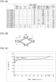
- FIG. 2A shows an anode support and a cell voltage in an organic hydride production apparatus according to each of Test Examples 1-11.
- FIG. 2B is a diagram used to describe long way of mesh LW, short way of mesh SW, and a strand width ST.
- FIG. 2C shows relationships between the Young's modulus of the anode support and the cell voltage.
- the anode was prepared according to the following procedure. First, as the base material of the anode, an expanded mesh having a predetermined mesh shape was prepared. Dry blasting was performed on the surfaces of the base material, and a cleaning process in a 20 percent sulfuric acid aqueous solution was performed. Thereafter, the base material was set in an arc ion plating apparatus using a Ti-Ta alloy target. Accordingly, Ti-Ta alloy coating was formed on the surfaces of the base material, at the base material temperature of 150 degrees C and the vacuum of 1.0 ⁇ 10 -2 Torr. The thickness of the coating was set to 2 ⁇ m.
- a mixed aqueous solution of iridium tetrachloride and tantalum pentoxide was applied, and heat treatment was performed thereon at 550 degrees C in an electric furnace.
- the anode containing equimolar amounts of iridium oxide and tantalum oxide was obtained.
- the amount of the catalyst in the anode was set to 12 g/m 2 in terms of the amount of Ir metal per electrode area.
- the Young's modulus of the anode was set to 40 N/mm 2 .
- catalyst ink for the cathode catalyst layer was prepared by adding 5 percent Nafion (registered trademark) Dispersion Solution (made by E. I. du Pont de Nemours and Company) to powder of PtRu/C catalyst TEC61E54 (made by TANAKA KIKINZOKU KOGYO K.K.) and by using a solvent as appropriate.
- the ratio of Nafion to carbon of the catalyst ink was set to 0.8.
- the catalyst ink was further prepared such that the noble metal amount (the amount of Pt and Ru) therein became 0.5 mg/cm 2 , and then applied to carbon paper GDL10BC (made by SGL Carbon) using a bar coater. Thereafter, the carbon paper was heated at 80 degrees C to dry the solvent component in the catalyst ink, so that the cathode catalyst layer was obtained.
- the noble metal amount the amount of Pt and Ru
- carbon paper GDL10BC made by SGL Carbon
- the diffusion layer was prepared by allowing carbon paper to support Pt particles.
- the Pt particles included in the diffusion layer function to promote the chemical reaction between hydrogen gas as a by-product and the unreacted hydrogenation target substance at the cathode.
- H 2 PtCl 6 ⁇ 6H 2 O and 1-propanol was mixed together to prepare a mixed solution.
- the amount of H 2 PtCl 6 ⁇ 6H 2 O added was adjusted such that the amount of Pt supported by the carbon paper became 0.02 mg/cm 2 .
- carbon paper GDL10BC (made by SGL Carbon) was immersed.
- the carbon paper was completely dried under a N 2 gas atmosphere at 60 degrees C. Subsequently, the carbon paper was immersed in a 1-mg NaBH 4 aqueous solution, and reduction treatment was performed for two hours. After the reduction treatment, the carbon paper was immersed in pure water to be cleaned. Thereafter, the carbon paper was dried and obtained as the diffusion layer. Also, as the electrolyte membrane, Nafion (registered trademark) 117 (made by E. I. du Pont de Nemours and Company) was prepared. The thickness of the electrolyte membrane was set to 0.175 mm. To the electrolyte membrane, the cathode catalyst layer and the diffusion layer were laminated, and hot pressing is performed thereon for three minutes at 120 degrees C and 1 MPa. Thus, a laminated body of the cathode and the electrolyte membrane was obtained.
- Nafion (registered trademark) 117 made by E. I. du Pont de Nemours and Company
- a complex of a cathode-side separator and a flow passage part, an anode-side separator, and a cathode spacer and an anode spacer were prepared.
- the complex and the anode-side separator used are made of titanium.
- the complex, the cathode spacer, the laminated body of the cathode and the electrolyte membrane, the anode, the anode support, the anode spacer, and the anode-side separator were laminated in this order.
- the resulting laminated body was then fitted, with pressure applied thereto from the outside. Pressing each layer using elastic force of the anode support could create a state in which the layers are in close contact with each other.
- the organic hydride production apparatus of Test Example 1 was obtained.
- the active electrode area of the organic hydride production apparatus was set to 100 cm 2 .
- a supply passage for the hydrogenation target substance was connected to the cathode chamber inlet in the cathode spacer.
- a discharge passage for the organic hydride was connected to the cathode chamber outlet in the cathode spacer.
- a supply passage for the anolyte was connected to the anode chamber inlet in the anode spacer.
- a discharge passage for the anolyte was connected to the cathode chamber outlet in the anode spacer.
- toluene as the catholyte was made to flow through the cathode chamber.
- 100 g/L sulfuric acid aqueous solution as the anolyte was made to flow through the anode chamber.
- the flow rate of the catholyte was set to 10 mL/minute.
- the flow rate of the anolyte was also set to 10 mL/minute.
- the electrolytic reaction was caused.
- the anolyte was supplied from the anolyte storage tank to the anode chamber using a pump, and then returned from the anode chamber to the anolyte storage tank to be circulated (batch operation).
- the anolyte was supplied through a lower part of the organic hydride production apparatus to the anode chamber. Also, the anolyte was circulated while an amount of water reduced by electrolysis was supplemented.
- the negative electrode and the positive electrode of a constant-current power supply were connected respectively to the cathode and the anode.
- the output current of the constant-current power supply was set to 40 A (0.4 A/cm 2 ) and applied to the organic hydride production apparatus.
- the cell voltage in the organic hydride production apparatus was measured.
- FIG. 2A shows the result.
- the organic hydride production apparatus of each of Test Examples 2-9 was prepared, in which the fiber diameter and the weight per unit area of the fiber constituting the anode support, and the thickness and the Young's modulus of the anode support were adjusted, as shown in FIG. 2A , and the other procedures were performed according to Test Example 1.
- the cell voltage in each organic hydride production apparatus was measured.
- FIG. 2A shows the results.
- the organic hydride production apparatus of each of Test Examples 10 and 11 was prepared, in which an anode support formed of an expanded mesh, instead of a sintered body of metal fiber, was used, as shown in FIG. 2A , and the other procedures were performed according to Test Example 1.
- the cell voltage in each organic hydride production apparatus was measured.
- FIG. 2A shows the results.
- the long way of mesh LW, the short way of mesh SW, and the strand width ST of the expanded mesh are as illustrated in FIG. 2B and are matters well known to persons skilled in the art.
- the cell voltage is 2.0 V or less.
- the cell voltage of 2.0 V corresponds to a cell voltage in alkaline water electrolysis. Accordingly, it is ascertained that, when the Young's modulus of the anode support is in the range from 0.2 N/mm 2 to 10 N/mm 2 inclusive, the efficiency of organic hydride production can be improved to be comparable to or greater than the efficiency of hydrogen production in alkaline water electrolysis. Further, it is ascertained that, when the Young's modulus of the anode support is in the range from 0.3 N/mm 2 to 1.2 N/mm 2 inclusive, the efficiency of organic hydride production can be further improved.
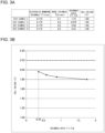
- FIG. 3A shows thicknesses of the electrolyte membrane and the anode included in the organic hydride production apparatus according to each of Test Examples 2 and 12-14, the ratio of the thicknesses, and the cell voltage.
- FIG. 3B shows relationships between the ratio of the thicknesses and the cell voltage.
- the organic hydride production apparatus of each of Test Examples 2 and 12-14 was prepared, in which the thickness T1 of the electrolyte membrane was fixed while the thickness T2 of the anode was adjusted to vary the thickness ratio T1/T2, as shown in FIG. 3A , and the other procedures were performed according to Test Example 1.
- the Young's modulus of the anode support was set to 0.3 N/mm 2 in all the Test Examples.
- the cell voltage in each organic hydride production apparatus was measured.
- FIG. 3A shows the results.
- FIG. 3B shows relationships between the ratio T1/T2 of the thickness T1 of the electrolyte membrane to the thickness T2 of the anode, and the cell voltage in the organic hydride production apparatus according to each Test Example.
- the thickness ratio T1/T2 is 0.35 or greater
- the cell voltage is less than 2.0 V. Accordingly, it is ascertained that, when the thickness ratio T1/T2 is set to 0.35 or greater, the efficiency of organic hydride production can be improved more certainly to be greater than the efficiency of hydrogen production in alkaline water electrolysis.
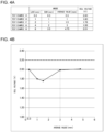
- the organic hydride production apparatus of each of Test Examples 15-19 was prepared, in which the long way of mesh LW and the short way of mesh SW of the mesh in the anode base material was varied, as shown in FIG. 4A , and the other procedures were performed according to Test Example 1.
- the Young's modulus of the anode support was set to 0.3 N/mm 2 in all the Test Examples.
- the cell voltage in each organic hydride production apparatus was measured.
- FIG. 4A shows the results.
- FIG. 4B shows relationships between the average value of the long way of mesh LW and the short way of mesh SW, and the cell voltage in the organic hydride production apparatus according to each Test Example.
- the cell voltage is 2.0 V or less. Accordingly, it is ascertained that, when the average value is set in the range from 0.3 mm to 3 mm inclusive, the efficiency of organic hydride production can be improved more certainly to be equal to or greater than the efficiency of hydrogen production in alkaline water electrolysis. Also, when the average value is greater than 0.3 mm and equal to or less than 3 mm, the cell voltage is less than 2.0 V.
- the present invention is applicable to an organic hydride production apparatus.
Landscapes
- Chemical & Material Sciences (AREA)
- Organic Chemistry (AREA)
- Engineering & Computer Science (AREA)
- Chemical Kinetics & Catalysis (AREA)
- Electrochemistry (AREA)
- Materials Engineering (AREA)
- Metallurgy (AREA)
- Inorganic Chemistry (AREA)
- Electrolytic Production Of Non-Metals, Compounds, Apparatuses Therefor (AREA)
- Electrodes For Compound Or Non-Metal Manufacture (AREA)
- Catalysts (AREA)
Claims (5)
- Verwendung einer Organisches-Hydrid-Herstellungsvorrichtung (100) zur Herstellung eines organischen Hydrids, wobei die Vorrichtung umfasst:eine Elektrolytmembran (102) mit Protonenleitfähigkeit;eine Kathode (104), bereitgestellt an einer Seite der Elektrolytmembran (102), die einen Kathodenkatalysator enthält, der zur Hydrierung eines Hydrierungs-Zielstoffs unter Verwendung von Protonen zur Herstellung eines organischen Hydrids verwendet wird;eine Anode (108), bereitgestellt gegenüber der einen Seite der Elektrolytmembran (102), die einen Anodenkatalysator (108a) enthält, der verwendet wird, um Wasser zu oxidieren, um Protonen zu erzeugen; undeinen Anodenträger (110), bereitgestellt gegenüber der Elektrolytmembran (102)-Seite der Anode (108), der die Anode (108) trägt, dadurch gekennzeichnet, dassder Anodenträger (110) aus einem elastischen porösen Körper gebildet ist, dessen Elastizitätsmodul 0,2 N/mm2 oder mehr und 10 N/mm2 oder weniger beträgt,wobei der elastische poröse Körper ein Sinterkörper aus Titanfaser ist,wobei die Elektrolytmembran (102), die Kathode (104), die Anode (108), der Anodenträger (110) und ein Strömungsdurchgangsteil (124) laminiert sind, um einen laminierten Körper zu bilden, wobei der laminierte Körper mit Abstandshaltern (122, 130) ausgestattet ist, und wobei die Verwendung den Schritt des Anlegens eines Klemmdrucks von 98,0665 kPa (1 kgf/cm2) oder weniger an den laminierten Körper unter Verwendung eines Paars von Separatoren (114a, 114b) umfasst.
- Verwendung nach Anspruch 1, wobei ein Verhältnis T1/T2 einer Dicke T1 der Elektrolytmembran (102) zu einer Dicke T2 der Anode (108) 0,35 oder mehr beträgt.
- Verwendung nach Anspruch 1 oder 2, wobei:die Anode (108) den Anodenkatalysator (108a) und ein Basismaterial (108b) vom Maschentyp umfasst, das den Anodenkatalysator (108a) trägt; unddie Form des Maschenmaterials in dem Basismaterial (108b) eine Rautenform ist, und ein Mittelwert der kurzen Strecke des Maschenmaterials SW und der langen Strecke des Maschenmaterials LW der Rautenform im Bereich von 0,3 mm bis 3 mm einschließlich liegt.
- Verwendung nach einem der Ansprüche 1 bis 3, wobei ein Anolyt, der eine wässrige Lösung umfasst, verwendet wird.
- Verwendung nach Anspruch 4, wobei die wässrige Lösung eine wässrige Schwefelsäurelösung, eine wässrige Salpetersäurelösung oder eine wässrige Salzsäurelösung mit einer Ionenleitfähigkeit von 0,01 S/cm oder mehr, gemessen bei 20 °C, ist.
Applications Claiming Priority (2)
| Application Number | Priority Date | Filing Date | Title |
|---|---|---|---|
| JP2017101419A JP6954561B2 (ja) | 2017-05-23 | 2017-05-23 | 有機ハイドライド製造装置 |
| PCT/JP2018/014110 WO2018216356A1 (ja) | 2017-05-23 | 2018-04-02 | 有機ハイドライド製造装置 |
Publications (4)
| Publication Number | Publication Date |
|---|---|
| EP3633071A1 EP3633071A1 (de) | 2020-04-08 |
| EP3633071A4 EP3633071A4 (de) | 2021-03-10 |
| EP3633071B1 true EP3633071B1 (de) | 2025-06-04 |
| EP3633071C0 EP3633071C0 (de) | 2025-06-04 |
Family
ID=64396748
Family Applications (1)
| Application Number | Title | Priority Date | Filing Date |
|---|---|---|---|
| EP18806725.0A Active EP3633071B1 (de) | 2017-05-23 | 2018-04-02 | Produktion von organischem hydrid |
Country Status (14)
| Country | Link |
|---|---|
| US (2) | US20200080212A1 (de) |
| EP (1) | EP3633071B1 (de) |
| JP (1) | JP6954561B2 (de) |
| KR (1) | KR102338318B1 (de) |
| CN (1) | CN110546307B (de) |
| AU (1) | AU2018272234B2 (de) |
| BR (1) | BR112019024205B1 (de) |
| CA (1) | CA3064173C (de) |
| CL (1) | CL2019003400A1 (de) |
| ES (1) | ES3032780T3 (de) |
| MY (1) | MY197574A (de) |
| PH (1) | PH12019550240B1 (de) |
| RU (1) | RU2733378C1 (de) |
| WO (1) | WO2018216356A1 (de) |
Families Citing this family (7)
| Publication number | Priority date | Publication date | Assignee | Title |
|---|---|---|---|---|
| US12371804B2 (en) * | 2020-06-10 | 2025-07-29 | Nederlandse Organisatie Voor Toegepast-Natuurwetenschappelijk Onderzoek Tno | Proton exchange membrane-based electrolyser device and method for manufacturing such a device |
| CN116529426A (zh) * | 2020-12-03 | 2023-08-01 | 引能仕株式会社 | 有机氢化物制造装置、水去除装置以及水去除方法 |
| AU2022369591A1 (en) * | 2021-10-20 | 2024-05-02 | Toray Industries, Inc. | Water electrolysis electrode structure, water electrolysis membrane electrode assembly, and water electrolysis device |
| JP7688057B2 (ja) * | 2023-01-18 | 2025-06-03 | 株式会社日阪製作所 | 電解合成装置 |
| WO2024219065A1 (ja) * | 2023-04-19 | 2024-10-24 | Eneos株式会社 | 有機ハイドライド製造装置および有機ハイドライド製造方法 |
| CN117026260B (zh) * | 2023-10-08 | 2024-09-20 | 陕西氢易能源科技有限公司 | 一种电化学加氢的pem反应器及其系统 |
| CN117210843A (zh) * | 2023-11-09 | 2023-12-12 | 北京亿华通科技股份有限公司 | 一种膜电极及其制备方法 |
Citations (1)
| Publication number | Priority date | Publication date | Assignee | Title |
|---|---|---|---|---|
| WO2016077433A1 (en) * | 2014-11-11 | 2016-05-19 | Envirowerks, Llc | A method and system for hydrogen production and a method of integrating the hydrogen production with an engine |
Family Cites Families (13)
| Publication number | Priority date | Publication date | Assignee | Title |
|---|---|---|---|---|
| US4693797A (en) * | 1979-08-03 | 1987-09-15 | Oronzio Denora Impianti Elettrochimici S.P.A. | Method of generating halogen and electrolysis cell |
| US5419824A (en) * | 1992-11-12 | 1995-05-30 | Weres; Oleh | Electrode, electrode manufacturing process and electrochemical cell |
| JP2700052B2 (ja) * | 1995-03-08 | 1998-01-19 | 工業技術院長 | 水素化物の製造方法 |
| US6365032B1 (en) * | 1998-12-31 | 2002-04-02 | Proton Energy Systems, Inc. | Method for operating a high pressure electrochemical cell |
| JP3772055B2 (ja) * | 1999-08-30 | 2006-05-10 | 株式会社トクヤマ | 電解槽 |
| WO2004036677A2 (en) * | 2002-10-14 | 2004-04-29 | Reinz-Dichtungs-Gmbh | Electrochemical system |
| RU2319797C1 (ru) * | 2006-08-14 | 2008-03-20 | Институт химии Дальневосточного отделения Российской академии наук (статус государственного учреждения) (Институт химии ДВО РАН) | Способ получения защитных покрытий на изделиях из нитинола |
| EP2660356A4 (de) | 2010-12-28 | 2014-07-09 | Jx Nippon Oil & Energy Corp | Vorrichtung zur hydrierung organischer verbindungen und hydrierungsverfahren |
| JP2013084360A (ja) * | 2011-10-06 | 2013-05-09 | Hitachi Ltd | 膜電極接合体及び有機ハイドライド製造装置 |
| EP3040449B1 (de) * | 2013-08-30 | 2018-03-21 | JX Nippon Oil & Energy Corporation | Elektrochemische reduktionsvorrichtung |
| CA2944134C (en) * | 2014-03-28 | 2019-07-09 | Yokohama National University | Device for producing organic hydride |
| CA2966834C (en) * | 2014-11-10 | 2022-08-30 | National University Corporation Yokohama National University | Oxygen-generating anode |
| JP6501141B2 (ja) * | 2014-11-21 | 2019-04-17 | 国立大学法人横浜国立大学 | 有機ハイドライド製造装置およびこれを用いた有機ハイドライドの製造方法 |
-
2017
- 2017-05-23 JP JP2017101419A patent/JP6954561B2/ja active Active
-
2018
- 2018-04-02 PH PH1/2019/550240A patent/PH12019550240B1/en unknown
- 2018-04-02 CA CA3064173A patent/CA3064173C/en active Active
- 2018-04-02 EP EP18806725.0A patent/EP3633071B1/de active Active
- 2018-04-02 BR BR112019024205-8A patent/BR112019024205B1/pt active IP Right Grant
- 2018-04-02 RU RU2019142468A patent/RU2733378C1/ru active
- 2018-04-02 MY MYPI2019006622A patent/MY197574A/en unknown
- 2018-04-02 KR KR1020197024275A patent/KR102338318B1/ko active Active
- 2018-04-02 AU AU2018272234A patent/AU2018272234B2/en active Active
- 2018-04-02 ES ES18806725T patent/ES3032780T3/es active Active
- 2018-04-02 CN CN201880025985.XA patent/CN110546307B/zh active Active
- 2018-04-02 WO PCT/JP2018/014110 patent/WO2018216356A1/ja not_active Ceased
-
2019
- 2019-11-18 US US16/686,369 patent/US20200080212A1/en not_active Abandoned
- 2019-11-22 CL CL2019003400A patent/CL2019003400A1/es unknown
-
2022
- 2022-07-06 US US17/858,464 patent/US20220333257A1/en not_active Abandoned
Patent Citations (1)
| Publication number | Priority date | Publication date | Assignee | Title |
|---|---|---|---|---|
| WO2016077433A1 (en) * | 2014-11-11 | 2016-05-19 | Envirowerks, Llc | A method and system for hydrogen production and a method of integrating the hydrogen production with an engine |
Also Published As
| Publication number | Publication date |
|---|---|
| CN110546307A (zh) | 2019-12-06 |
| JP2018197364A (ja) | 2018-12-13 |
| US20200080212A1 (en) | 2020-03-12 |
| WO2018216356A1 (ja) | 2018-11-29 |
| KR20190103434A (ko) | 2019-09-04 |
| EP3633071A4 (de) | 2021-03-10 |
| ES3032780T3 (en) | 2025-07-24 |
| JP6954561B2 (ja) | 2021-10-27 |
| CA3064173A1 (en) | 2018-11-29 |
| MY197574A (en) | 2023-06-26 |
| CA3064173C (en) | 2022-04-26 |
| PH12019550240B1 (en) | 2023-11-15 |
| CL2019003400A1 (es) | 2020-04-17 |
| BR112019024205B1 (pt) | 2024-02-06 |
| BR112019024205A2 (pt) | 2020-06-02 |
| AU2018272234A1 (en) | 2019-12-05 |
| CN110546307B (zh) | 2022-02-11 |
| EP3633071C0 (de) | 2025-06-04 |
| US20220333257A1 (en) | 2022-10-20 |
| PH12019550240A1 (en) | 2020-12-07 |
| KR102338318B1 (ko) | 2021-12-09 |
| AU2018272234B2 (en) | 2021-06-24 |
| RU2733378C1 (ru) | 2020-10-01 |
| EP3633071A1 (de) | 2020-04-08 |
Similar Documents
| Publication | Publication Date | Title |
|---|---|---|
| US20220333257A1 (en) | Organic hydride production device | |
| US11519082B2 (en) | Organic hydride production apparatus and method for producing organic hydride | |
| KR102471656B1 (ko) | 유기 수소화물 제조 장치 및 이것을 사용한 유기 수소화물의 제조 방법 | |
| US10889903B2 (en) | Oxygen-generating anode | |
| WO2018037774A1 (ja) | カソード、有機ハイドライド製造用電解セル及び有機ハイドライドの製造方法 | |
| WO2015146944A1 (ja) | 有機ハイドライド製造装置 | |
| JP2017179601A (ja) | 電解セル用セパレータ、電解セル、電気化学還元装置及び芳香族炭化水素化合物の水素化体の製造方法 | |
| EP3040449B1 (de) | Elektrochemische reduktionsvorrichtung | |
| EP2808425A1 (de) | Vorrichtung für elektrochemische reduktion und verfahren zur herstellung von stickstoff mit einer heterocyclischen aromatischen verbindung oder einer aromatischen kohlenwasserstoffverbindung | |
| JP7789358B2 (ja) | カソード、膜電極接合体及び有機ハイドライド製造装置 | |
| EP3040448A1 (de) | Elektrochemische reduktionsvorrichtung | |
| AU2023323068A1 (en) | Apparatus for producing organic hydride | |
| AU2024259307A1 (en) | Organic hydride production device and organic hydride production method |
Legal Events
| Date | Code | Title | Description |
|---|---|---|---|
| STAA | Information on the status of an ep patent application or granted ep patent |
Free format text: STATUS: THE INTERNATIONAL PUBLICATION HAS BEEN MADE |
|
| PUAI | Public reference made under article 153(3) epc to a published international application that has entered the european phase |
Free format text: ORIGINAL CODE: 0009012 |
|
| STAA | Information on the status of an ep patent application or granted ep patent |
Free format text: STATUS: REQUEST FOR EXAMINATION WAS MADE |
|
| 17P | Request for examination filed |
Effective date: 20191108 |
|
| AK | Designated contracting states |
Kind code of ref document: A1 Designated state(s): AL AT BE BG CH CY CZ DE DK EE ES FI FR GB GR HR HU IE IS IT LI LT LU LV MC MK MT NL NO PL PT RO RS SE SI SK SM TR |
|
| AX | Request for extension of the european patent |
Extension state: BA ME |
|
| DAV | Request for validation of the european patent (deleted) | ||
| DAX | Request for extension of the european patent (deleted) | ||
| REG | Reference to a national code |
Ref country code: DE Ref legal event code: R079 Free format text: PREVIOUS MAIN CLASS: C25B0009020000 Ipc: C25B0009000000 Ref document number: 602018082433 Country of ref document: DE |
|
| A4 | Supplementary search report drawn up and despatched |
Effective date: 20210205 |
|
| RIC1 | Information provided on ipc code assigned before grant |
Ipc: C25B 9/00 20210101AFI20210201BHEP Ipc: C22B 11/00 20060101ALI20210201BHEP |
|
| STAA | Information on the status of an ep patent application or granted ep patent |
Free format text: STATUS: EXAMINATION IS IN PROGRESS |
|
| 17Q | First examination report despatched |
Effective date: 20220629 |
|
| P01 | Opt-out of the competence of the unified patent court (upc) registered |
Effective date: 20230525 |
|
| GRAP | Despatch of communication of intention to grant a patent |
Free format text: ORIGINAL CODE: EPIDOSNIGR1 |
|
| STAA | Information on the status of an ep patent application or granted ep patent |
Free format text: STATUS: GRANT OF PATENT IS INTENDED |
|
| INTG | Intention to grant announced |
Effective date: 20250213 |
|
| GRAS | Grant fee paid |
Free format text: ORIGINAL CODE: EPIDOSNIGR3 |
|
| GRAA | (expected) grant |
Free format text: ORIGINAL CODE: 0009210 |
|
| STAA | Information on the status of an ep patent application or granted ep patent |
Free format text: STATUS: THE PATENT HAS BEEN GRANTED |
|
| AK | Designated contracting states |
Kind code of ref document: B1 Designated state(s): AL AT BE BG CH CY CZ DE DK EE ES FI FR GB GR HR HU IE IS IT LI LT LU LV MC MK MT NL NO PL PT RO RS SE SI SK SM TR |
|
| REG | Reference to a national code |
Ref country code: GB Ref legal event code: FG4D |
|
| REG | Reference to a national code |
Ref country code: CH Ref legal event code: EP |
|
| REG | Reference to a national code |
Ref country code: DE Ref legal event code: R096 Ref document number: 602018082433 Country of ref document: DE |
|
| REG | Reference to a national code |
Ref country code: IE Ref legal event code: FG4D |
|
| REG | Reference to a national code |
Ref country code: ES Ref legal event code: FG2A Ref document number: 3032780 Country of ref document: ES Kind code of ref document: T3 Effective date: 20250724 |
|
| P04 | Withdrawal of opt-out of the competence of the unified patent court (upc) registered |
Free format text: CASE NUMBER: APP_31467/2025 Effective date: 20250701 |
|
| U01 | Request for unitary effect filed |
Effective date: 20250627 |
|
| U07 | Unitary effect registered |
Designated state(s): AT BE BG DE DK EE FI FR IT LT LU LV MT NL PT RO SE SI Effective date: 20250703 |
|
| PG25 | Lapsed in a contracting state [announced via postgrant information from national office to epo] |
Ref country code: GR Free format text: LAPSE BECAUSE OF FAILURE TO SUBMIT A TRANSLATION OF THE DESCRIPTION OR TO PAY THE FEE WITHIN THE PRESCRIBED TIME-LIMIT Effective date: 20250905 |
|
| PG25 | Lapsed in a contracting state [announced via postgrant information from national office to epo] |
Ref country code: PL Free format text: LAPSE BECAUSE OF FAILURE TO SUBMIT A TRANSLATION OF THE DESCRIPTION OR TO PAY THE FEE WITHIN THE PRESCRIBED TIME-LIMIT Effective date: 20250604 |
|
| PG25 | Lapsed in a contracting state [announced via postgrant information from national office to epo] |
Ref country code: HR Free format text: LAPSE BECAUSE OF FAILURE TO SUBMIT A TRANSLATION OF THE DESCRIPTION OR TO PAY THE FEE WITHIN THE PRESCRIBED TIME-LIMIT Effective date: 20250604 |
|
| PG25 | Lapsed in a contracting state [announced via postgrant information from national office to epo] |
Ref country code: RS Free format text: LAPSE BECAUSE OF FAILURE TO SUBMIT A TRANSLATION OF THE DESCRIPTION OR TO PAY THE FEE WITHIN THE PRESCRIBED TIME-LIMIT Effective date: 20250904 |