EP3632542A1 - Co shift or reverse shift catalyst structure and production method thereof, co shift or reverse shift reaction device, production method of carbon dioxide and hydrogen, and production method of carbon monoxide and water - Google Patents
Co shift or reverse shift catalyst structure and production method thereof, co shift or reverse shift reaction device, production method of carbon dioxide and hydrogen, and production method of carbon monoxide and water Download PDFInfo
- Publication number
- EP3632542A1 EP3632542A1 EP18809577.2A EP18809577A EP3632542A1 EP 3632542 A1 EP3632542 A1 EP 3632542A1 EP 18809577 A EP18809577 A EP 18809577A EP 3632542 A1 EP3632542 A1 EP 3632542A1
- Authority
- EP
- European Patent Office
- Prior art keywords
- shift
- reverse shift
- structured catalyst
- reverse
- metal
- Prior art date
- Legal status (The legal status is an assumption and is not a legal conclusion. Google has not performed a legal analysis and makes no representation as to the accuracy of the status listed.)
- Withdrawn
Links
Images


Classifications
-
- B—PERFORMING OPERATIONS; TRANSPORTING
- B01—PHYSICAL OR CHEMICAL PROCESSES OR APPARATUS IN GENERAL
- B01J—CHEMICAL OR PHYSICAL PROCESSES, e.g. CATALYSIS OR COLLOID CHEMISTRY; THEIR RELEVANT APPARATUS
- B01J29/00—Catalysts comprising molecular sieves
- B01J29/03—Catalysts comprising molecular sieves not having base-exchange properties
- B01J29/035—Microporous crystalline materials not having base exchange properties, such as silica polymorphs, e.g. silicalites
-
- B—PERFORMING OPERATIONS; TRANSPORTING
- B01—PHYSICAL OR CHEMICAL PROCESSES OR APPARATUS IN GENERAL
- B01J—CHEMICAL OR PHYSICAL PROCESSES, e.g. CATALYSIS OR COLLOID CHEMISTRY; THEIR RELEVANT APPARATUS
- B01J29/00—Catalysts comprising molecular sieves
- B01J29/04—Catalysts comprising molecular sieves having base-exchange properties, e.g. crystalline zeolites
- B01J29/06—Crystalline aluminosilicate zeolites; Isomorphous compounds thereof
- B01J29/08—Crystalline aluminosilicate zeolites; Isomorphous compounds thereof of the faujasite type, e.g. type X or Y
- B01J29/10—Crystalline aluminosilicate zeolites; Isomorphous compounds thereof of the faujasite type, e.g. type X or Y containing iron group metals, noble metals or copper
- B01J29/14—Iron group metals or copper
-
- B—PERFORMING OPERATIONS; TRANSPORTING
- B01—PHYSICAL OR CHEMICAL PROCESSES OR APPARATUS IN GENERAL
- B01J—CHEMICAL OR PHYSICAL PROCESSES, e.g. CATALYSIS OR COLLOID CHEMISTRY; THEIR RELEVANT APPARATUS
- B01J29/00—Catalysts comprising molecular sieves
- B01J29/04—Catalysts comprising molecular sieves having base-exchange properties, e.g. crystalline zeolites
- B01J29/06—Crystalline aluminosilicate zeolites; Isomorphous compounds thereof
- B01J29/40—Crystalline aluminosilicate zeolites; Isomorphous compounds thereof of the pentasil type, e.g. types ZSM-5, ZSM-8 or ZSM-11, as exemplified by patent documents US3702886, GB1334243 and US3709979, respectively
- B01J29/42—Crystalline aluminosilicate zeolites; Isomorphous compounds thereof of the pentasil type, e.g. types ZSM-5, ZSM-8 or ZSM-11, as exemplified by patent documents US3702886, GB1334243 and US3709979, respectively containing iron group metals, noble metals or copper
- B01J29/46—Iron group metals or copper
-
- B—PERFORMING OPERATIONS; TRANSPORTING
- B01—PHYSICAL OR CHEMICAL PROCESSES OR APPARATUS IN GENERAL
- B01J—CHEMICAL OR PHYSICAL PROCESSES, e.g. CATALYSIS OR COLLOID CHEMISTRY; THEIR RELEVANT APPARATUS
- B01J29/00—Catalysts comprising molecular sieves
- B01J29/04—Catalysts comprising molecular sieves having base-exchange properties, e.g. crystalline zeolites
- B01J29/06—Crystalline aluminosilicate zeolites; Isomorphous compounds thereof
- B01J29/65—Crystalline aluminosilicate zeolites; Isomorphous compounds thereof of the ferrierite type, e.g. types ZSM-21, ZSM-35 or ZSM-38, as exemplified by patent documents US4046859, US4016245 and US4046859, respectively
- B01J29/66—Crystalline aluminosilicate zeolites; Isomorphous compounds thereof of the ferrierite type, e.g. types ZSM-21, ZSM-35 or ZSM-38, as exemplified by patent documents US4046859, US4016245 and US4046859, respectively containing iron group metals, noble metals or copper
- B01J29/68—Iron group metals or copper
-
- B—PERFORMING OPERATIONS; TRANSPORTING
- B01—PHYSICAL OR CHEMICAL PROCESSES OR APPARATUS IN GENERAL
- B01J—CHEMICAL OR PHYSICAL PROCESSES, e.g. CATALYSIS OR COLLOID CHEMISTRY; THEIR RELEVANT APPARATUS
- B01J29/00—Catalysts comprising molecular sieves
- B01J29/04—Catalysts comprising molecular sieves having base-exchange properties, e.g. crystalline zeolites
- B01J29/06—Crystalline aluminosilicate zeolites; Isomorphous compounds thereof
- B01J29/70—Crystalline aluminosilicate zeolites; Isomorphous compounds thereof of types characterised by their specific structure not provided for in groups B01J29/08 - B01J29/65
- B01J29/72—Crystalline aluminosilicate zeolites; Isomorphous compounds thereof of types characterised by their specific structure not provided for in groups B01J29/08 - B01J29/65 containing iron group metals, noble metals or copper
- B01J29/76—Iron group metals or copper
-
- B—PERFORMING OPERATIONS; TRANSPORTING
- B01—PHYSICAL OR CHEMICAL PROCESSES OR APPARATUS IN GENERAL
- B01J—CHEMICAL OR PHYSICAL PROCESSES, e.g. CATALYSIS OR COLLOID CHEMISTRY; THEIR RELEVANT APPARATUS
- B01J29/00—Catalysts comprising molecular sieves
- B01J29/04—Catalysts comprising molecular sieves having base-exchange properties, e.g. crystalline zeolites
- B01J29/06—Crystalline aluminosilicate zeolites; Isomorphous compounds thereof
- B01J29/70—Crystalline aluminosilicate zeolites; Isomorphous compounds thereof of types characterised by their specific structure not provided for in groups B01J29/08 - B01J29/65
- B01J29/72—Crystalline aluminosilicate zeolites; Isomorphous compounds thereof of types characterised by their specific structure not provided for in groups B01J29/08 - B01J29/65 containing iron group metals, noble metals or copper
- B01J29/76—Iron group metals or copper
- B01J29/7669—MTW-type, e.g. ZSM-12, NU-13, TPZ-12 or Theta-3
-
- B—PERFORMING OPERATIONS; TRANSPORTING
- B01—PHYSICAL OR CHEMICAL PROCESSES OR APPARATUS IN GENERAL
- B01J—CHEMICAL OR PHYSICAL PROCESSES, e.g. CATALYSIS OR COLLOID CHEMISTRY; THEIR RELEVANT APPARATUS
- B01J35/00—Catalysts, in general, characterised by their form or physical properties
- B01J35/30—Catalysts, in general, characterised by their form or physical properties characterised by their physical properties
- B01J35/391—Physical properties of the active metal ingredient
- B01J35/393—Metal or metal oxide crystallite size
-
- B—PERFORMING OPERATIONS; TRANSPORTING
- B01—PHYSICAL OR CHEMICAL PROCESSES OR APPARATUS IN GENERAL
- B01J—CHEMICAL OR PHYSICAL PROCESSES, e.g. CATALYSIS OR COLLOID CHEMISTRY; THEIR RELEVANT APPARATUS
- B01J35/00—Catalysts, in general, characterised by their form or physical properties
- B01J35/30—Catalysts, in general, characterised by their form or physical properties characterised by their physical properties
- B01J35/391—Physical properties of the active metal ingredient
- B01J35/394—Metal dispersion value, e.g. percentage or fraction
-
- B—PERFORMING OPERATIONS; TRANSPORTING
- B01—PHYSICAL OR CHEMICAL PROCESSES OR APPARATUS IN GENERAL
- B01J—CHEMICAL OR PHYSICAL PROCESSES, e.g. CATALYSIS OR COLLOID CHEMISTRY; THEIR RELEVANT APPARATUS
- B01J35/00—Catalysts, in general, characterised by their form or physical properties
- B01J35/40—Catalysts, in general, characterised by their form or physical properties characterised by dimensions, e.g. grain size
- B01J35/45—Nanoparticles
-
- B—PERFORMING OPERATIONS; TRANSPORTING
- B01—PHYSICAL OR CHEMICAL PROCESSES OR APPARATUS IN GENERAL
- B01J—CHEMICAL OR PHYSICAL PROCESSES, e.g. CATALYSIS OR COLLOID CHEMISTRY; THEIR RELEVANT APPARATUS
- B01J37/00—Processes, in general, for preparing catalysts; Processes, in general, for activation of catalysts
- B01J37/0009—Use of binding agents; Moulding; Pressing; Powdering; Granulating; Addition of materials ameliorating the mechanical properties of the product catalyst
- B01J37/0018—Addition of a binding agent or of material, later completely removed among others as result of heat treatment, leaching or washing,(e.g. forming of pores; protective layer, desintegrating by heat)
-
- B—PERFORMING OPERATIONS; TRANSPORTING
- B01—PHYSICAL OR CHEMICAL PROCESSES OR APPARATUS IN GENERAL
- B01J—CHEMICAL OR PHYSICAL PROCESSES, e.g. CATALYSIS OR COLLOID CHEMISTRY; THEIR RELEVANT APPARATUS
- B01J37/00—Processes, in general, for preparing catalysts; Processes, in general, for activation of catalysts
- B01J37/02—Impregnation, coating or precipitation
- B01J37/0201—Impregnation
- B01J37/0205—Impregnation in several steps
-
- B—PERFORMING OPERATIONS; TRANSPORTING
- B01—PHYSICAL OR CHEMICAL PROCESSES OR APPARATUS IN GENERAL
- B01J—CHEMICAL OR PHYSICAL PROCESSES, e.g. CATALYSIS OR COLLOID CHEMISTRY; THEIR RELEVANT APPARATUS
- B01J37/00—Processes, in general, for preparing catalysts; Processes, in general, for activation of catalysts
- B01J37/08—Heat treatment
- B01J37/10—Heat treatment in the presence of water, e.g. steam
-
- B—PERFORMING OPERATIONS; TRANSPORTING
- B01—PHYSICAL OR CHEMICAL PROCESSES OR APPARATUS IN GENERAL
- B01J—CHEMICAL OR PHYSICAL PROCESSES, e.g. CATALYSIS OR COLLOID CHEMISTRY; THEIR RELEVANT APPARATUS
- B01J37/00—Processes, in general, for preparing catalysts; Processes, in general, for activation of catalysts
- B01J37/16—Reducing
- B01J37/18—Reducing with gases containing free hydrogen
-
- C—CHEMISTRY; METALLURGY
- C01—INORGANIC CHEMISTRY
- C01B—NON-METALLIC ELEMENTS; COMPOUNDS THEREOF; METALLOIDS OR COMPOUNDS THEREOF NOT COVERED BY SUBCLASS C01C
- C01B3/00—Hydrogen; Gaseous mixtures containing hydrogen; Separation of hydrogen from mixtures containing it; Purification of hydrogen; Reversible storage of hydrogen
- C01B3/02—Production of hydrogen; Production of gaseous mixtures containing hydrogen
- C01B3/06—Production of hydrogen; Production of gaseous mixtures containing hydrogen by reaction of inorganic compounds containing electro-positively bound hydrogen with inorganic reducing agents
- C01B3/12—Production of hydrogen; Production of gaseous mixtures containing hydrogen by reaction of inorganic compounds containing electro-positively bound hydrogen with inorganic reducing agents by reaction of water vapour with carbon monoxide
- C01B3/16—Production of hydrogen; Production of gaseous mixtures containing hydrogen by reaction of inorganic compounds containing electro-positively bound hydrogen with inorganic reducing agents by reaction of water vapour with carbon monoxide using catalysts
-
- C—CHEMISTRY; METALLURGY
- C01—INORGANIC CHEMISTRY
- C01B—NON-METALLIC ELEMENTS; COMPOUNDS THEREOF; METALLOIDS OR COMPOUNDS THEREOF NOT COVERED BY SUBCLASS C01C
- C01B3/00—Hydrogen; Gaseous mixtures containing hydrogen; Separation of hydrogen from mixtures containing it; Purification of hydrogen; Reversible storage of hydrogen
- C01B3/02—Production of hydrogen; Production of gaseous mixtures containing hydrogen
- C01B3/32—Production of hydrogen; Production of gaseous mixtures containing hydrogen by reaction of gaseous or liquid organic compounds with gasifying agents, e.g. water, carbon dioxide or air
- C01B3/34—Production of hydrogen; Production of gaseous mixtures containing hydrogen by reaction of gaseous or liquid organic compounds with gasifying agents, e.g. water, carbon dioxide or air by reaction of hydrocarbons with gasifying agents
- C01B3/48—Production of hydrogen; Production of gaseous mixtures containing hydrogen by reaction of gaseous or liquid organic compounds with gasifying agents, e.g. water, carbon dioxide or air by reaction of hydrocarbons with gasifying agents followed by reaction of water vapour with carbon monoxide
-
- C—CHEMISTRY; METALLURGY
- C01—INORGANIC CHEMISTRY
- C01B—NON-METALLIC ELEMENTS; COMPOUNDS THEREOF; METALLOIDS OR COMPOUNDS THEREOF NOT COVERED BY SUBCLASS C01C
- C01B32/00—Carbon; Compounds thereof
- C01B32/40—Carbon monoxide
-
- C—CHEMISTRY; METALLURGY
- C01—INORGANIC CHEMISTRY
- C01B—NON-METALLIC ELEMENTS; COMPOUNDS THEREOF; METALLOIDS OR COMPOUNDS THEREOF NOT COVERED BY SUBCLASS C01C
- C01B5/00—Water
-
- B—PERFORMING OPERATIONS; TRANSPORTING
- B01—PHYSICAL OR CHEMICAL PROCESSES OR APPARATUS IN GENERAL
- B01J—CHEMICAL OR PHYSICAL PROCESSES, e.g. CATALYSIS OR COLLOID CHEMISTRY; THEIR RELEVANT APPARATUS
- B01J2229/00—Aspects of molecular sieve catalysts not covered by B01J29/00
- B01J2229/10—After treatment, characterised by the effect to be obtained
- B01J2229/14—After treatment, characterised by the effect to be obtained to alter the inside of the molecular sieve channels
-
- B—PERFORMING OPERATIONS; TRANSPORTING
- B01—PHYSICAL OR CHEMICAL PROCESSES OR APPARATUS IN GENERAL
- B01J—CHEMICAL OR PHYSICAL PROCESSES, e.g. CATALYSIS OR COLLOID CHEMISTRY; THEIR RELEVANT APPARATUS
- B01J2229/00—Aspects of molecular sieve catalysts not covered by B01J29/00
- B01J2229/10—After treatment, characterised by the effect to be obtained
- B01J2229/18—After treatment, characterised by the effect to be obtained to introduce other elements into or onto the molecular sieve itself
- B01J2229/186—After treatment, characterised by the effect to be obtained to introduce other elements into or onto the molecular sieve itself not in framework positions
-
- B—PERFORMING OPERATIONS; TRANSPORTING
- B01—PHYSICAL OR CHEMICAL PROCESSES OR APPARATUS IN GENERAL
- B01J—CHEMICAL OR PHYSICAL PROCESSES, e.g. CATALYSIS OR COLLOID CHEMISTRY; THEIR RELEVANT APPARATUS
- B01J2235/00—Indexing scheme associated with group B01J35/00, related to the analysis techniques used to determine the catalysts form or properties
-
- B—PERFORMING OPERATIONS; TRANSPORTING
- B01—PHYSICAL OR CHEMICAL PROCESSES OR APPARATUS IN GENERAL
- B01J—CHEMICAL OR PHYSICAL PROCESSES, e.g. CATALYSIS OR COLLOID CHEMISTRY; THEIR RELEVANT APPARATUS
- B01J2235/00—Indexing scheme associated with group B01J35/00, related to the analysis techniques used to determine the catalysts form or properties
- B01J2235/30—Scanning electron microscopy; Transmission electron microscopy
-
- C—CHEMISTRY; METALLURGY
- C01—INORGANIC CHEMISTRY
- C01B—NON-METALLIC ELEMENTS; COMPOUNDS THEREOF; METALLOIDS OR COMPOUNDS THEREOF NOT COVERED BY SUBCLASS C01C
- C01B2203/00—Integrated processes for the production of hydrogen or synthesis gas
- C01B2203/02—Processes for making hydrogen or synthesis gas
- C01B2203/0283—Processes for making hydrogen or synthesis gas containing a CO-shift step, i.e. a water gas shift step
-
- C—CHEMISTRY; METALLURGY
- C01—INORGANIC CHEMISTRY
- C01B—NON-METALLIC ELEMENTS; COMPOUNDS THEREOF; METALLOIDS OR COMPOUNDS THEREOF NOT COVERED BY SUBCLASS C01C
- C01B2203/00—Integrated processes for the production of hydrogen or synthesis gas
- C01B2203/10—Catalysts for performing the hydrogen forming reactions
- C01B2203/1041—Composition of the catalyst
- C01B2203/1047—Group VIII metal catalysts
- C01B2203/1052—Nickel or cobalt catalysts
-
- C—CHEMISTRY; METALLURGY
- C01—INORGANIC CHEMISTRY
- C01B—NON-METALLIC ELEMENTS; COMPOUNDS THEREOF; METALLOIDS OR COMPOUNDS THEREOF NOT COVERED BY SUBCLASS C01C
- C01B2203/00—Integrated processes for the production of hydrogen or synthesis gas
- C01B2203/10—Catalysts for performing the hydrogen forming reactions
- C01B2203/1041—Composition of the catalyst
- C01B2203/1047—Group VIII metal catalysts
- C01B2203/1052—Nickel or cobalt catalysts
- C01B2203/1058—Nickel catalysts
-
- C—CHEMISTRY; METALLURGY
- C01—INORGANIC CHEMISTRY
- C01B—NON-METALLIC ELEMENTS; COMPOUNDS THEREOF; METALLOIDS OR COMPOUNDS THEREOF NOT COVERED BY SUBCLASS C01C
- C01B2203/00—Integrated processes for the production of hydrogen or synthesis gas
- C01B2203/10—Catalysts for performing the hydrogen forming reactions
- C01B2203/1041—Composition of the catalyst
- C01B2203/1076—Copper or zinc-based catalysts
-
- Y—GENERAL TAGGING OF NEW TECHNOLOGICAL DEVELOPMENTS; GENERAL TAGGING OF CROSS-SECTIONAL TECHNOLOGIES SPANNING OVER SEVERAL SECTIONS OF THE IPC; TECHNICAL SUBJECTS COVERED BY FORMER USPC CROSS-REFERENCE ART COLLECTIONS [XRACs] AND DIGESTS
- Y02—TECHNOLOGIES OR APPLICATIONS FOR MITIGATION OR ADAPTATION AGAINST CLIMATE CHANGE
- Y02P—CLIMATE CHANGE MITIGATION TECHNOLOGIES IN THE PRODUCTION OR PROCESSING OF GOODS
- Y02P20/00—Technologies relating to chemical industry
- Y02P20/50—Improvements relating to the production of bulk chemicals
- Y02P20/52—Improvements relating to the production of bulk chemicals using catalysts, e.g. selective catalysts
Definitions
- the present invention relates to a structured catalyst for CO shift or reverse shift including a support of a porous structure and a CO shift or reverse shift catalyst, a method for producing the same, a CO shift or reverse shift reactor, a method for producing carbon dioxide and hydrogen, and a method for producing carbon monoxide and water.
- coal gasification combined power generation that can further reduce CO 2 emission through efficient power generation is performed.
- coal gasification combined power generation coal is converted to a flammable gas in a gasifier at high temperature and high pressure, the converted generated gas is used as a fuel for power generation, and the waste water released at the time of conversion to the flammable gas is used for power generation in a steam turbine.
- the compound present in the generated gas is mostly carbon monoxide (CO), and contains few percentages of carbon dioxide (CO 2 ) and hydrocarbon (C n H m ). Accordingly, in order to recover CO 2 from the generated gas, CO present in the generated gas must be converted to CO 2 .
- the generated gas is mixed with water vapor (H 2 O), and converted to CO 2 using a CO shift catalyst by the CO shift reaction represented by Formula (1), and the converted CO 2 is recovered with a CO 2 recovery equipment.
- Examples of the CO shift catalyst include a Cu-Zn catalyst having CO shift reaction activity in a low-temperature region at 300°C or lower, and a Fe-Cr catalyst having CO shift reaction activity in a high-temperature region at 300°C or higher. Furthermore, CO shift catalysts having activity in a high-temperature region can cause problem of carbon deposition, and thus requires excessive addition of water vapor to CO. On the other hand, excessive addition of water vapor can lead to the decrease in power generation efficiency, so that the reduction of the added amount of water vapor is required while the amount is excessive relative to CO.
- Patent Document 1 proposes a CO shift catalyst that includes either molybdenum (Mo) or iron (Fe) as a main component, an active component including either nickel (Ni) or ruthenium (Ru) as a minor component, and a complex oxide composed any two or more of titanium (Ti), zirconium (Zr), cerium (Ce), silica (Si), aluminum (Al), and lanthanum (La) as a support supporting the active component, the CO shift catalyst having been sintered at a high temperature of 550°C or higher to increase the average pore diameter of the catalyst, and having excellent durability and maintaining stable CO shift reaction for a long period of time even in cases where carbon deposition occurs.
- Mo molybdenum
- Fe iron
- Ru ruthenium
- La lanthanum
- the generated gas may include H 2 S and may be poisoned with a sulfur component depending on the catalyst species, so that desulfurization operation is required in the previous stage. Therefore, as a catalyst having CO shift reaction activity even in the presence of H 2 S, Patent Document 2 proposes a catalyst including at least Mo and Ni, and TiO 2 as a support supporting these active components.
- the generated gas is mostly CO and the CO shift reaction is exothermic, so that the CO shift reaction increases the temperature of the CO shift catalyst.
- the CO shift catalyst particles are exposed to high temperatures for a long period of time, aggregation (sintering) of the CO shift catalyst particles and the support components tends to occur.
- catalytic activity decreases due to the decrease in the effective surface area of the catalyst, and the catalyst life becomes shorter than normal. Therefore, the catalyst itself must be replaced or regenerated over a short period of time, which leads to the problem that the replacement operation is cumbersome and resources saving cannot be achieved.
- the reaction is preferably performed at a high temperature of 600°C or higher.
- the temperature of 600°C or higher is usually much higher than the normal temperature of the shift reaction, the use of a catalyst for a normal shift reaction is difficult from the perspective of calcination resistance of the catalytic metal (Patent Document 3).
- Ni catalysts such as Ni/Al 2 O 3 and NiO/ZnO has been reported (Non-patent Document 1).
- Ni catalysts have a problem that they can cause methanation to generate methane, and decrease the carbon monoxide concentration. Therefore, there is a desire to develop a catalyst for reverse shift reaction that can minimize generation of methane.
- Non-Patent Document 1 Industrial Catalyst News No. 107, Aug 1, 2017
- An object of the present invention is to provide a structured catalyst for CO shift or reverse shift for realizing a long life time by suppressing the decline in function, a method for producing the same, a CO shift or reverse shift reactor, a method for producing carbon dioxide and hydrogen, and a method for producing carbon monoxide and water.
- the structured catalyst for CO shift or reverse shift that suppresses the decline in catalytic activity of the CO shift or reverse shift catalytic substance and realizes a long life time can be obtained by including:
- a structured catalyst for CO shift or reverse shift that can realize a long life time by suppressing the decline in function, a method for producing the same, a CO shift or reverse shift reactor, a method for producing carbon dioxide and hydrogen, and a method for producing carbon monoxide and water.
- the structured catalyst for CO shift and the structured catalyst for reverse shift exhibit high catalytic activity and good heat resistance, so that particularly the structured catalyst for reverse shift is beneficial for use in reverse shift reactions.
- FIG. 1 is a diagram schematically illustrating a configuration of a structured catalyst for CO shift or reverse shift according to an embodiment of the present invention.
- FIG. 1A is a perspective view (partially illustrated in cross section), and
- FIG. 1B is a partially enlarged cross-sectional view.
- the structured catalyst for CO shift or reverse shift in FIG. 1 is an example of the structured catalyst for CO shift or reverse shift, and the shape, dimension, and the like of each of the configurations according to the present invention are not limited to those illustrated in FIG. 1 .
- a structured catalyst for CO shift or reverse shift 1 includes a support 10 of a porous structure composed of a zeolite-type compound, and at least one CO shift or reverse shift catalytic substance 20 present in the support 10.
- CO shift or reverse shift catalytic substance 20 may be any substance having CO shift catalytic capacity (CO shift or reverse shift catalytic activity), and is preferably made of metal nanoparticles.
- the metal nanoparticles are described in detail below.
- the support 10 is a porous structure, and as illustrated in FIG. 1B , a plurality of pores 11a, 11a, ... are preferably formed so as to have channels 11 connecting with each other.
- the CO shift or reverse shift catalytic substance 20 is present at least in the channel 11 of the support 10, and is preferably held at least in the channel 11 of the support 10.
- the structured catalyst for CO shift or reverse shift 1 suppresses the decline in the CO shift or reverse shift catalytic activity due to aggregation between the CO shift or reverse shift catalytic substances 20, and extends the life of the structured catalyst for CO shift or reverse shift 1.
- the replacement frequency of the structured catalyst for CO shift or reverse shift 1 can be reduced, and the amount of waste of the used structured catalyst for CO shift or reverse shift 1 can be significantly reduced, and thereby can save resources.
- the structural body can be subjected to an external force from the fluid.
- the CO shift or reverse shift catalytic substance is only held in the state of attachment to the outer surface of the support 10, there is a problem in that it is easily detached from the outer surface of the support 10 due to the influence of the external force from the fluid.
- the CO shift or reverse shift catalytic substance 20 is present at least in the channel 11 of the support 10, and therefore, even if subjected to an external force caused by a fluid, the CO shift or reverse shift catalytic substance 20 is less likely detached from the support 10. That is, when the structured catalyst for CO shift or reverse shift 1 is in a fluid, the fluid flows into the channel 11 from the pore 11a of the support 10, so that the speed of the fluid flowing through the channel 11 is likely slower than the speed of the fluid flowing on the outer surface of the support 10 due to the flow path resistance (frictional force).
- the pressure applied to the CO shift or reverse shift catalytic substance 20 present in the channel 11 from the fluid is lower than the pressure applied to the CO shift or reverse shift catalytic substance 20 from the fluid outside of the support 10.
- detachment of the CO shift or reverse shift catalytic substance 20 present in the support 10 can be effectively suppressed, and the catalytic activity of the CO shift or reverse shift catalytic substance 20 can be stably maintained over a long period of time.
- the flow path resistance as described above is thought to be larger so that the channel 11 of the support 10 has a plurality of bends and branches, and the interior of the support 10 becomes a more complex three-dimensional structure.
- the channel 11 has any one of a one-dimensional pore, a two-dimensional pore, and a three-dimensional pore defined by the framework of the zeolite-type compound and an enlarged pore portion different from any of the one-dimensional pore, the two-dimensional pore, and the three-dimensional pore.
- the CO shift or reverse shift catalytic substance 20 is preferably present at least in the enlarged pore portion 12, and is more preferably embedded at least in the enlarged pore portion 12.
- the enlarged pore portion 12 preferably connects with the plurality of pores 11a, 11a constituting any one of the one-dimensional pore, the two-dimensional pore, and the three-dimensional pore.
- the "one-dimensional pore” refers to a tunnel-type or cage-type pore forming a one-dimensional channel, or a plurality of tunnel-type or cage-type pores (a plurality of one-dimensional channels) forming a plurality of one-dimensional channels.
- the "two-dimensional pore” refers to a two-dimensional channel in which a plurality of one-dimensional channels is connected two-dimensionally.
- the "three-dimensional pore” refers to a three-dimensional channel in which a plurality of one-dimensional channels is connected three-dimensionally.
- the term “embedding” refers to a state in which the CO shift or reverse shift catalytic substance 20 is included in the support 10.
- the CO shift or reverse shift catalytic substance 20 and the support 10 need not necessarily be in direct contact with each other, but may be indirectly held by the support 10 with other substances (e.g., a surfactant, etc.) interposed between the CO shift or reverse shift catalytic substance 20 and the support 10.
- other substances e.g., a surfactant, etc.
- FIG. 1B illustrates the case in which the CO shift or reverse shift catalytic substance 20 is embedded in the enlarged pore portion 12
- the CO shift or reverse shift catalytic substance 20 is not limited to this configuration only, and the CO shift or reverse shift catalytic substance 20 may be present in the channel 11 with a portion thereof protruding outward of the enlarged pore portion 12.
- the CO shift or reverse shift catalytic substance 20 may be partially embedded in a portion of the channel 11 other than the enlarged pore portion 12 (for example, an inner wall portion of the channel 11), or may be held by fixing, for example.
- the channel 11 is formed three-dimensionally by including a branch portion or a merging portion within the support 10, and the enlarged pore portion 12 is preferably provided in the branch portion or the merging portion of the channel 11.
- the average inner diameter D F of the channel 11 formed in the support 10 is calculated from the average value of the short diameter and the long diameter of the pore 11a constituting any of the one-dimensional pore, the two-dimensional pore, and the three-dimensional pore. For example, it is from 0.1 nm to 1.5 nm, and preferably from 0.5 nm to 0.8 nm.
- the inner diameter D E of the enlarged pore portion 12 is, for example, from 0.5 nm to 50 nm, preferably from 1.1 nm to 40 nm, and more preferably from 1.1 nm to 3.3 nm.
- the inner diameter D E of the enlarged pore portion 12 depends on the pore diameter of the precursor material (A) described below and the average particle size Dc of the CO shift or reverse shift catalytic substance 20 to be embedded.
- the inner diameter D E of the enlarged pore portion 12 is sized so that the enlarged pore portion 12 is able to embed the CO shift or reverse shift catalytic substance 20.
- the support 10 is composed of a zeolite-type compound.
- zeolite-type compounds include zeolite analog compounds such as zeolites (aluminosilicate), cation exchanged zeolites, silicate compounds such as silicalite, aluminoborate, alminoarsenate salts, and germanate salts; and phosphate-based zeolite analog materials such as molybdenum phosphate.
- the zeolite-type compound is preferably a silicate compound.
- the framework of the zeolite-type compound is selected from FAU type (Y type or X type), MTW type, MFI type (ZSM-5), FER type (ferrierite), LTA type (A type), MWW type (MCM-22), MOR type (mordenite), LTL type (L type), and BEA type (beta type).
- FAU type Y type or X type
- MTW type MFI type
- ZSM-5 FER type
- LTA type A type
- MCM-22 MOR type
- MOR type memory
- LTL type L type
- BEA type beta type
- it is MFI type, and more preferably ZSM-5.
- a plurality of pores having a pore diameter corresponding to each framework is formed in the zeolite-type compound.
- the maximum pore diameter of MFI type is 0.636 nm (6.36 ⁇ ) and the average pore diameter is 0.560 nm (5.60 ⁇ ).
- the metal nanoparticles 20 are primary particles or secondary particles formed by aggregating primary particles, but the average particle size D C of the metal nanoparticles 20 is preferably larger than the average inner diameter D F of the channel 11 and not greater than the inner diameter D E of the enlarged pore portion 12 (D F ⁇ D C ⁇ D E ). Such metal nanoparticles 20 are suitably embedded in the enlarged pore portion 12 within the channel 11, and the movement of the metal nanoparticles 20 within the support 10 is restricted.
- the metal nanoparticles 20 are subjected to an external force from a CO-containing mixed gas containing CO and water vapor (H 2 O) as a fluid, movement of the metal nanoparticles 20 within the support 10 is suppressed, and contact between the metal nanoparticles 20, 20, ... present in the enlarged pore portions 12, 12, ... dispersed in the channel 11 of the support 10 is effectively prevented.
- a CO-containing mixed gas containing CO and water vapor (H 2 O) as a fluid
- the average particle size Dc of the metal nanoparticles 20 is preferably from 0.08 nm to 30 nm, more preferably from 0.08 nm to 25 nm, and further preferably from 0.4 nm to 11.0 nm, and particularly preferably from 0.8 nm to 2.7 nm.
- the ratio (D C /D F ) of the average particle size Dc of the metal nanoparticles 20 to the average inner diameter D F of the channel 11 is preferably from 0.05 to 300, more preferably from 0.1 to 30, even more preferably from 1.1 to 30, and particularly preferably from 1.4 to 3.6.
- the metal element 20 (M) of the metal nanoparticles is preferably contained in 0.5 to 2.5 mass% relative to the structured catalyst for CO shift or reverse shift 1, and more preferably from 0.5 to 1.5 mass% relative to the structured catalyst for CO shift or reverse shift 1.
- the metal element (M) is Co
- the content of Co element (mass%) is expressed as ⁇ (mass of Co element)/(mass of all elements in the structured catalyst for CO shift or reverse shift 1) ⁇ ⁇ 100.
- the metal nanoparticles only need to be nanoparticles constituted by at least one type of metal or metal oxide.
- the metal nanoparticles may be constituted of a single metal or metal oxide, or may be constituted of a mixture of two or more types of metals or metal oxides.
- the "metal" constituting the metal nanoparticles refers to an elemental metal containing one type of metal element (M) and a metal alloy containing two or more types of metal elements (M), and the term is a generic term for a metal containing one or more metal elements (M).
- metal oxide refers to an oxide containing one type of metal element (M) and a complex oxide containing two or more types of metal elements (M), and the term is a generic name for oxides containing one or more metal elements (M).
- Examples of such a metal include platinum (Pt), palladium (Pd), ruthenium (Ru), nickel (Ni), cobalt (Co), molybdenum (Mo), tungsten (W), iron (Fe), chromium (Cr), cerium (Ce), copper (Cu), magnesium (Mg), and aluminum (Al).
- platinum Pt
- palladium Pd
- ruthenium Ru
- nickel Ni
- cobalt Co
- Mo molybdenum
- Mo molybdenum
- W tungsten
- iron (Fe) iron
- Cr chromium
- Ce cerium
- Cu copper
- Al aluminum
- any one of metal described above is the major component.
- metal oxides examples include cobalt oxide (CoO x ), nickel oxide (NiOx), iron oxide (FeOx), copper oxide (CuOx), zirconium oxide (ZrOx), cerium oxide (CeOx), aluminum oxide (AlO x ), niobium oxide (NbO x ), titanium oxide (TiOx), bismuth oxide (BiOx), molybdenum oxide (MoO x ), vanadium oxide (VO x ), and chromium oxide (CrOx).
- CoO x cobalt oxide
- NiOx nickel oxide
- iron oxide (FeOx) iron oxide
- CuOx copper oxide
- ZrOx zirconium oxide
- CeOx cerium oxide
- AlO x aluminum oxide
- niobium oxide NbO x
- bismuth oxide (BiOx) bismuth oxide
- MoO x molybdenum oxide
- the metal nanoparticles are preferably nanoparticles composed of at least one type of metal or metal oxide selected from the group consisting of cobalt, nickel, iron, and copper, more preferably nanoparticles composed of at least one type of metal or metal oxide selected from the group consisting of cobalt, iron, and copper, and is particularly preferably nanoparticles composed of copper or copper oxide.
- the ratio of silicon (Si) constituting the support 10 to the metal element (M) constituting the metal nanoparticles 20 is preferably from 10 to 1000, and more preferably from 50 to 200. If the ratio is greater than 1000, the CO shift or reverse shift catalytic activity reduces, so that the action of the CO shift or reverse shift catalytic substance may not be sufficiently obtained. On the other hand, if the ratio is smaller than 10, the proportion of the metal nanoparticles 20 becomes too large, and the strength of the support 10 tends to decrease. Note that the metal nanoparticles 20 refer to the nanoparticles that are held or supported in the support 10, and do not include metal nanoparticles adhered to the outer surface of the support 10.
- the structured catalyst for CO shift or reverse shift 1 includes the support 10 of a porous structure and at least one CO shift or reverse shift catalytic substance 20 present in the support 10, as described above.
- the structured catalyst for CO shift 1 exhibits CO shift catalytic capacity of the CO shift catalytic substance 20 present in the support 10 by contact of the CO shift catalytic substance 20 with a CO-containing mixed gas.
- the CO-containing mixed gas in contact with the outer surface 10a of the structured catalyst for CO shift 1 flows into the support 10 through the pore 11a formed in the outer surface 10a and guided into the channel 11, moves through the channel 11, and exits to the exterior of the structured catalyst for CO shift 1 through the other pore 11a.
- contacting with the CO shift catalytic substance 20 held in the channel 11 results in a CO shift catalytic reaction of the CO shift catalytic substance 20.
- the structured catalyst for reverse shift 1 exhibits reverse shift catalytic capacity by the reverse shift catalytic substance 20 by contact of the reverse shift catalytic substance 20 present in the support 10 with the CO 2 containing mixed gas containing CO 2 and H 2 .
- the CO 2 -containing mixed gas in contact with the outer surface 10a of the structured catalyst for reverse shift 1 flows into the support 10 through the pore 11a formed in the outer surface 10a and guided into the channel 11, moves through the channel 11, and exits to the exterior of the structured catalyst for reverse shift 1 through the other pore 11a.
- contacting with the reverse shift catalytic substance 20 held in the channel 11 results in a reverse shift catalytic reaction of the reverse shift catalytic substance 20.
- the structured catalyst for CO shift or reverse shift 1 has molecular sieving capability due to the support 10 being a porous structure.
- the molecular sieving capability of the structured catalyst for CO shift or reverse shift 1 to transmit H 2 , H 2 O, CO, and CO 2 , which are contained in the synthetic gas as a fluid is described below.
- molecules of H 2 , H 2 O, CO, and CO 2 having a size that is less than or equal to the pore diameter of the pore 11a, in other words, less than or equal to the inner diameter of the channel 11, can flow into the support 10.
- other molecule 15 having a size exceeding the pore diameter of the pore 11a cannot flow into the support 10. In this way, when the CO-containing mixed gas and the CO 2 -containing mixed gas contain a plurality of types of compounds, the reaction of compounds that cannot flow into the support 10 is restricted, and a compound capable of flowing into the support 10 is allowed to react.
- the CO shift or reverse shift catalytic substance 20 is embedded in the enlarged pore portion 12 of the channel 11.
- the CO shift or reverse shift catalytic substance 20 is made of metal nanoparticles, if the average particle size Dc of the metal nanoparticles is larger than the average inner diameter D F of the channel 11 and smaller than the inner diameter D E of the enlarged pore portion 12 (D F ⁇ D C ⁇ D E ), a small channel 13 is formed between the metal nanoparticles and the enlarged pore portion 12.
- the CO-containing mixed gas or CO 2 -containing mixed gas that has flown into the small channel 13 comes into contact with the metal nanoparticles. Because these metal nanoparticles are embedded in the enlarged pore portion 12, movement within the support 10 is restricted. As a result, aggregation between the metal nanoparticles in the support 10 is prevented. As a result, a large contact area is stably maintained between the metal nanoparticles and the CO-containing mixed gas or the CO 2 -containing mixed gas as a fluid.
- a CO shift or reverse shift reactor having a structured catalyst for CO shift or reverse shift may be formed using the structured catalyst for CO shift or reverse shift 1.
- a CO shift or reverse shift reactor that achieves the same effects as described above is obtained.
- FIG. 3 is a flowchart illustrating a method for producing the structured catalyst for CO shift or reverse shift 1 of FIG. 1 .
- An example of the method for producing the structured catalyst for CO shift or reverse shift will be described below as an example of the case in which the CO shift or reverse shift catalytic substance present in the support is made of metal nanoparticles.
- Step S1 Preparation step
- the precursor material (A) is prepared for obtaining a support of a porous structure composed of the zeolite-type compound.
- the precursor material (A) is preferably a regular mesopore material, and may be appropriately selected according to the type (composition) of the zeolite-type compound constituting the support of the structured catalyst for CO shift or reverse shift.
- the regular mesopore material is preferably a compound including a Si-O skeleton in which pores having a pore diameter of 1 to 50 nm are uniformly sized and regularly developed one-dimensionally, two-dimensionally, or three-dimensionally. While such a regular mesopore material is obtained as a variety of synthetic materials depending on the synthetic conditions. Specific examples of the synthetic material include SBA-1, SBA-15, SBA-16, KIT-6, FSM-16, and MCM-41. Among them, MCM-41 is preferred.
- the pore diameter of SBA-1 is from 10 to 30 nm
- the pore diameter of SBA-15 is from 6 to 10 nm
- the pore diameter of SBA-16 is 6 nm
- the pore diameter of KIT-6 is 9 nm
- the pore diameter of FSM-16 is from 3 to 5 nm
- the pore diameter of MCM-41 is from 1 to 10 nm.
- regular mesopore material include mesoporous silica, mesoporous aluminosilicate, and mesoporous metallosilicate.
- the precursor material (A) may be a commercially available product or a synthetic product.
- the precursor material (A) can be synthesized by a known method for synthesizing a regular mesopore material. For example, a mixed solution including a raw material containing the constituent elements of the precursor material (A) and a molding agent for defining the structure of the precursor material (A) is prepared, and the pH is adjusted as necessary to perform hydrothermal treatment (hydrothermal synthesis). Thereafter, the precipitate (product) obtained by hydrothermal treatment is recovered (e.g., filtered), washed and dried as necessary, and then calcined to obtain a precursor material (A) which is a powdered regular mesopore material.
- examples of the solvent of the mixed solution include water, an organic solvent such as alcohol, or a mixed solvent thereof.
- the raw material is selected according to the type of the support, and its examples include silica agents such as tetraethoxysilane (TEOS), fumed silica, and quartz sand.
- TEOS tetraethoxysilane
- various types of surfactants, block copolymers, and the like can be used as the molding agent, and it is preferably selected depending on the type of the synthetic materials of the regular mesopore material.
- a surfactant such as hexadecyltrimethylammonium bromide is preferable when producing MCM-41.
- the hydrothermal treatment can be performed at from 0 to 2000 kPa at 80 to 800°C for 5 hours to 240 hours in a sealed container.
- the calcination treatment may be performed in air, at 350 to 850°C for 2 hours to 30 hours.
- Step S2 Impregnating step
- the prepared precursor material (A) is then impregnated with the metal-containing solution to obtain the precursor material (B).
- the metal-containing solution is a solution containing a metal component (for example, a metal ion) corresponding to the metal element (M) constituting the metal nanoparticles of the structured catalyst for CO shift or reverse shift, and can be prepared, for example, by dissolving a metal salt containing a metal element (M) in a solvent.
- metal salts include metal salts such as chlorides, hydroxides, oxides, sulfates, and nitrates. Of these, nitrates are preferable.
- the solvent that can be used include water, an organic solvent such as alcohol, or a mixed solvent thereof.
- the method for impregnating the precursor material (A) with the metal-containing solution is not particularly limited; however, for example, the metal-containing solution is preferably added in portions in a plurality of times while mixing the powdered precursor material (A) before the calcination step described below.
- the surfactant is preferably added to the precursor material (A) as the additive before adding the metal-containing solution to the precursor material (A) from the perspective of allowing the metal-containing solution to enter the pores of the precursor material (A) more easily.
- additives serve to cover the outer surface of the precursor material (A) and inhibit the subsequently added metal-containing solution from adhering to the outer surface of the precursor material (A), making it easier for the metal-containing solution to enter the pores of the precursor material (A).
- non-ionic surfactants such as polyoxyethylene oleyl ether, polyoxyethylene alkyl ether, and polyoxyethylene alkylphenyl ether. It is believed that these surfactants do not adhere to the interior of the pores because their molecular size is large and cannot enter the pores of the precursor material (A), and will not interfere with the penetration of the metal-containing solution into the pores.
- the method for adding the non-ionic surfactant for example, it is preferable to add from 50 to 500 mass% of the non-ionic surfactant to the precursor material (A) prior to the calcination step described below.
- the added amount of the non-ionic surfactant to the precursor material (A) is less than 50 mass%, the aforementioned suppressing action will not easily occur, and when greater than 500 mass% of the non-ionic surfactant is added to the precursor material (A), the viscosity is too high, which is not preferable.
- the added amount of the non-ionic surfactant to the precursor material (A) is a value within the range described above.
- the added amount of the metal-containing solution added to the precursor material (A) is preferably adjusted as appropriate in consideration of the amount of the metal element (M) contained in the metal-containing solution with which the precursor material (A) is impregnated (that is, the amount of the metal element (M) present in the precursor material (B)).
- the value obtained by converting the added amount of the metal-containing solution added to the precursor material (A) to a ratio of silicon (Si) constituting the precursor material (A) to a metal element (M) included in the metal-containing solution added to the precursor material (A) is preferably adjusted to from 10 to 1000, and more preferably from 50 to 200.
- the surfactant when added to the precursor material (A) as an additive prior to adding the metal-containing solution to the precursor material (A), the value obtained by converting the added amount of the metal-containing solution added to the precursor material (A) to a ratio of number of atoms Si/M is adjusted to from 50 to 200, thereby including the metal element (M) of the metal nanoparticles in the structured catalyst for CO shift or reverse shift in an amount from 0.5 to 2.5 mass%.
- the added amount of the metal element (M) present within the pores is generally proportional to the amount of the metal-containing solution added to the precursor material (A) in a case where the metal concentration of the metal-containing solution, the presence or absence of additives, and other conditions such as temperature and pressure are the same.
- the amount of the metal element (M) present in the precursor material (B) is also in a proportional relationship to the amount of the metal element constituting the metal nanoparticles embedded in the support of the structured catalyst for CO shift or reverse shift.
- the pores of the precursor material (A) can be sufficiently impregnated with the metal-containing solution, and thus the amount of the metal nanoparticles present in the support of the structured catalyst for CO shift or reverse shift can be adjusted.
- a washing treatment may be performed as necessary.
- the solvent of the washing solution that can be used include water, an organic solvent such as alcohol, or a mixed solvent thereof.
- the precursor material (A) is preferably impregnated with the metal-containing solution, and after the washing treatment is performed as necessary, the precursor material (A) is further subjected to drying treatment. Drying treatments include overnight natural drying and high temperature drying at 150°C or lower.
- Step S3 Calcination step
- a precursor material (C) is obtained by calcining the precursor material (B) obtained by impregnating the precursor material (A) for obtaining the support of the porous structure composed of zeolite-type compound with the metal-containing solution.
- the calcination treatment is preferably performed in air, at 350 to 850°C for 2 hours to 30 hours.
- the metal component that has impregnated the pores of the regular mesopore material undergoes crystal growth by the calcination treatment, and metal nanoparticles are formed in the pores.
- Step S4 Hydrothermal treatment step
- a mixed solution of the precursor material (C) and the structure directing agent is then prepared, and the precursor material (C) obtained by calcining the precursor material (B) is hydrothermally treated to obtain a structured catalyst for CO shift or reverse shift.
- the structure directing agent is a molding agent for defining the skeletal structure of the support of the structured catalyst for CO shift or reverse shift, and may be, for example, a surfactant.
- the structure directing agent is preferably selected according to the skeletal structure of the support of the structured catalyst for CO shift or reverse shift, and is preferably, for example, a surfactant such as tetramethylammonium bromide (TMABr), tetraethylammonium bromide (TEABr), and tetrapropylammonium bromide (TPABr).
- TMABr tetramethylammonium bromide
- TEABr tetraethylammonium bromide
- TPABr tetrapropylammonium bromide
- the mixing of the precursor material (C) and the structure directing agent may be performed during the hydrothermal treatment step or may be performed before the hydrothermal treatment step.
- the method for preparing the mixed solution is not particularly limited, and the precursor material (C), the structure directing agent, and the solvent may be mixed simultaneously, or each of the dispersion solutions may be mixed after the precursor material (C) and the structure directing agent are each dispersed in individual solutions.
- the solvent that can be used include water, an organic solvent such as alcohol, or a mixed solvent thereof.
- it is preferable that the pH of the mixed solution is adjusted using an acid or a base prior to performing the hydrothermal treatment.
- the hydrothermal treatment can be performed by a known method.
- the hydrothermal treatment can be preferably performed at from 0 to 2000 kPa at 80 to 800°C for 5 hours to 240 hours in a sealed container.
- the hydrothermal treatment is preferably performed under a basic condition.
- the reaction mechanism here is not necessarily clear, by performing hydrothermal treatment using the precursor material (C) as a raw material, the skeletal structure as the regular mesopore material of the precursor material (C) becomes increasingly disrupted.
- the action of the structure directing agent forms a new skeletal structure (porous structure) as the support of the structured catalyst for CO shift or reverse shift while maintaining the position of the metal nanoparticles within the pores of the precursor material (C).
- the structured catalyst for CO shift or reverse shift obtained in this way includes the support having the porous structure and metal nanoparticles present in the support, and the support has a channel in which the plurality of pores connect with each other by the porous structure, and at least a portion of the metal nanoparticles are present in the channel of the support.
- a mixed solution in which the precursor material (C) and the structure directing agent are mixed is prepared, and the precursor material (C) is subjected to hydrothermal treatment, which is not a limitation.
- the precursor material (C) may be subjected to hydrothermal treatment without mixing the precursor material (C) and the structure directing agent.
- the precipitate obtained after hydrothermal treatment is preferably washed, dried, and calcined as necessary after recovery (e.g., filtration).
- the washing solution that can be used include water, an organic solvent such as alcohol, or a mixed solution thereof. Drying treatments include overnight natural drying and high temperature drying at 150°C or lower. Note that when calcination treatment is performed in the state in which there is a large amount of moisture remaining in the precipitate, the skeletal structure as a support of the structured catalyst for CO shift or reverse shift may be broken, and thus it is preferable to dry the precipitate sufficiently.
- the calcination treatment may be performed in air, at 350 to 850°C for 2 hours to 30 hours.
- Such calcination treatment burns out the structure directing agent that has been attached to the structured catalyst for CO shift or reverse shift.
- the structured catalyst for CO shift or reverse shift may be used as-is without subjecting the recovered precipitate to calcination, depending on the intended use.
- the environment in which the structured catalyst for CO shift or reverse shift is used is a high temperature environment in an oxidizing atmosphere
- exposing the structured catalyst for CO shift or reverse shift to a usage environment for a period of time allows the structure directing agent to be burned out and to obtain a structured catalyst for CO shift or reverse shift similar to that when subjected to calcination treatment.
- the obtained structured catalyst for CO shift or reverse shift can be used as is.
- the producing method described above is an example in which the metal element (M) contained in the metal-containing solution that impregnates the precursor material (A) is a metal species resistant to oxidization (e.g., a noble metal).
- a metal species resistant to oxidization e.g., a noble metal
- the hydrothermally treated precursor material (C) is preferably subjected to reduction treatment after the hydrothermal treatment step.
- the metal element (M) contained in the metal-containing solution is an easily oxidized metal species
- the metal component is oxidized by the heat treatment in the step (steps S3 to S4) after the impregnating step (step S2). Therefore, metal oxide nanoparticles are present in the support formed in the hydrothermal treatment step (step S4).
- step S5 reduction treatment step.
- the reduction treatment reduces the metal oxide nanoparticles present in the support, and metal nanoparticles corresponding to the metal element (M) constituting the metal oxide nanoparticles are formed.
- M metal element
- the metal oxide nanoparticles are reduced by exposing the structural body to a usage environment for a certain period of time, so that a structured catalyst for CO shift or reverse shift similar to that obtained when subjected to reduction treatment is obtained.
- the obtained structured catalyst for CO shift or reverse shift can be used in the form including oxide nanoparticles in the support.
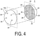
- FIG. 4 is a schematic view illustrating a modified example of the structured catalyst for CO shift or reverse shift 1 in FIG. 1 .
- the structured catalyst for CO shift or reverse shift 1 of FIG. 1 illustrates the case in which it includes the support 10 and the CO shift or reverse shift catalytic substance 20 present in the support 10, the structured catalyst for CO shift or reverse shift 1 is not limited to this configuration.
- the structured catalyst for CO shift or reverse shift 2 may further include at least one CO shift or reverse shift catalytic substance 30 held on the outer surface 10a of the support 10.
- This CO shift or reverse shift catalytic substance 30 is a substance that exhibits one or more catalytic capacities.
- the catalytic capacity of the other CO shift or reverse shift catalytic substance 30 may be the same or different from the catalytic capacity of the CO shift or reverse shift catalytic substance 20.
- the material of the other CO shift or reverse shift catalytic substance 30 may be the same as or different from the material of the CO shift or reverse shift catalytic substance 20. According to this configuration, the content of the CO shift or reverse shift catalytic substance held in the structured catalyst for CO shift or reverse shift 2 can be increased, and the catalytic activity of the CO shift or reverse shift catalytic substance can be further promoted.
- the content of the CO shift or reverse shift catalytic substance 20 present in the support 10 is preferably greater than that of the other CO shift or reverse shift catalytic substance 30 held on the outer surface 10a of the support 10.
- the catalytic capacity of the CO shift or reverse shift catalytic substance 20 held inside the support 10 becomes dominant, and catalytic capacities of the CO shift or reverse shift catalytic substances are stably exhibited.
- a method for producing carbon dioxide and hydrogen that generates carbon dioxide and hydrogen from carbon monoxide and water (water vapor) using a catalyst includes a support 10 of a porous structure composed of a zeolite-type compound, and at least one type of metal nanoparticles 20 present in the support 10, in which the support 10 has channels 11 connecting with each other, and the metal nanoparticles 20 includes a structured catalyst for CO shift 1 present at least in an enlarged pore portion 12 of the channels 11 of the support 10. That is, the present invention provides a method for producing carbon dioxide and hydrogen that generates carbon dioxide and hydrogen from carbon monoxide and water (water vapor) using the structured catalyst for CO shift described above.
- the raw material used in the method for producing carbon dioxide and hydrogen using the CO shift reaction is not particularly limited as long as it is a synthetic gas composed mainly of gaseous water and carbon monoxide, and is preferably a synthetic gas having the molar ratio of water vapor to carbon monoxide in the raw material gas of from 1 to 100.
- the reaction conditions in the CO shift reaction may be set according to, for example, the concentration of the gas component in the raw material gas and the content of the catalyst component.
- the reaction temperature in the CO shift reaction is preferably from 150 to 300°C
- the reaction pressure is preferably from 1 to 100 atmospheres (absolute pressure)
- the space velocity of the raw material gas (excluding water vapor) is preferably from 1000 to 100000 (1/h).
- the CO shift reaction may be carried out in a known process of CO shift reaction, for example, in a fixed bed, a supercritical fixed bed, a slurry bed, or a fluidized bed.
- a known process of CO shift reaction for example, in a fixed bed, a supercritical fixed bed, a slurry bed, or a fluidized bed.
- the used of the structured catalyst for CO shift according to the present invention allows to obtain the same effects as those exhibited by the structured catalyst for CO shift in the above-described method for producing carbon dioxide and hydrogen.
- the present invention may provide a method for producing carbon dioxide and hydrogen, including converting carbon monoxide and water to carbon dioxide and hydrogen using the CO shift reactor described above.
- the CO shift reactor is not particularly limited as long as it is capable performing a CO shift reaction using the above-described structured catalyst for CO shift, and may be a commonly used reactor such as a reaction vessel, a reaction tube, or a reaction column.
- the use of the CO shift reactor having a structured catalyst for CO shift allows to achieve the same effect as those exhibited by the structured catalyst for CO shift described above.
- a method for producing carbon monoxide and water that produces carbon monoxide and water (water vapor) from carbon dioxide and hydrogen using a catalyst is also provided.
- the catalyst includes a support 10 of a porous structure composed of a zeolite-type compound, and at least one type of metal nanoparticles 20 present in the support 10, the support 10 having channels 11 connecting with each other, and the metal nanoparticles 20 including a structured catalyst for reverse shift 1 present at least in the enlarged pore portion 12 of the channels 11 of the support 10. That is, the present invention provides a method for producing carbon monoxide and water that produces carbon monoxide and water (water vapor) from carbon dioxide and hydrogen using the structured catalyst for reverse shift described above.
- the raw material used in the method for producing carbon monoxide and water using such a reverse shift reaction is not particularly limited as long as it is a synthetic gas composed mainly of molecular hydrogen and carbon dioxide.
- the compositions of CO 2 , H 2 CO, and H 2 O are controlled by chemical equilibrium, and the composition of the resulting gas depends on the reaction temperature and the CO 2 /H 2 ratio of the raw material gas.
- unreacted CO 2 and generated H 2 O are removed from the gas after reaction to increase the proportion of H 2 in the raw material gas, thereby increasing the proportion of H 2 in the resulting synthetic gas.
- the reverse shift reaction may be effectively performed at a reaction temperature of 300°C or higher and 900°C or lower, and the reaction temperature is preferably from 400°C to 850°C, and more preferably from 500°C to 800°C.
- the reaction temperature is lower than 300°C, the carbon acid gas tends not to be sufficiently converted to carbon monoxide because of equilibrium.
- the reaction temperature exceeds 900°C, the performance of the associated equipment such as piping must be improved, and this is not preferable from the perspective of producing costs.
- the reverse shift reaction may also be performed by a known reaction process of a reverse shift reaction, for example, in a fixed bed, a supercritical fixed bed, a slurry bed, or a fluidized bed.
- a reverse shift reaction for example, carbon monoxide and water (water vapor) are generated from carbon dioxide and hydrogen, or in reverse shift reaction
- the use of the structured catalyst for reverse shift according to the present invention allows to obtain the same effects as those exhibited by the structured catalyst for reverse shift even in the method for producing carbon monoxide and water described above.
- the present invention may also provide a method for producing carbon monoxide and water by converting carbon dioxide and hydrogen to carbon monoxide and water (water vapor) using the reverse shift reactor described above.
- the reverse shift reactor is not particularly limited as long as it can perform reverse shift reaction using the structured catalyst for reverse shift, and may be a common reactor such as a reaction vessel, a reaction tube, or a reaction column.
- the use of the reverse shift reactor having the structured catalyst for reverse shift allows to obtain the same effect as that exhibited by the structured catalyst for reverse shift.
- the structured catalyst for CO shift or reverse shift according to the present invention is a catalyst that can be applied to both the CO shift reaction and the reverse shift reaction, and can realize a long life by suppressing the decrease in catalytic function in both reactions.
- a structured catalyst for CO shift or reverse shift exhibits high catalytic activity, for example, the use of the structured catalyst for reverse shift in a reverse shift reaction allows a reverse shift reaction in a high temperature environment that could not be achieved by related art.
- a mixed aqueous solution was prepared by mixing a silica agent (tetraethoxysilane (TEOS), manufactured by Wako Pure Chemical Industries, Ltd.) and a surfactant as the molding agent.
- TEOS tetraethoxysilane
- the pH was adjusted as appropriate, and hydrothermal treatment was performed at 80 to 350°C for 100 hours in a sealed container. Thereafter, the produced precipitate was filtered out, washed with water and ethanol, and then calcined in air at 600°C for 24 hours to obtain the precursor material (A) of the type and having the pore diameter shown in Tables 1 to 8. Note that the following surfactant was used depending on the type of the precursor material (A).
- metal-containing aqueous solution was prepared by dissolving a metal salt containing the metal element (M) in water according to the metal element (M) constituting the metal nanoparticles of the type shown in Tables 1 to 8. Following metal salts were used in accordance with the type of metal nanoparticles ("metal nanoparticles: metal salt").
- the added amount of the metal-containing aqueous solution added to the precursor material (A) was adjusted so that the value obtained by converting to a ratio of silicon (Si) constituting the precursor material (A) to a metal element (M) included in the metal-containing solution is in Tables 1 to 8.
- the precursor material (B) impregnated with the metal-containing aqueous solution obtained as described above was calcined in air at 600°C for 24 hours to obtain the precursor material (C).
- the precursor material (C) obtained as described above and the structure directing agent shown in Tables 1 to 8 were mixed to produce a mixed aqueous solution.
- Hydrothermal treatment was performed under the conditions of at 80 to 350°C, at pH and time shown in Tables 1 to 8 in a sealed container. Thereafter, the produced precipitate was filtered off, washed with water, dried at 100°C for 12 hours or longer, and then calcined in air at 600°C for 24 hours. The calcined product was then recovered and reduction treatment was performed under the inflow of hydrogen gas at 400°C for 350 minutes to obtain catalytic structural bodies containing a support and metal nanoparticles as a catalytic substance shown in Tables 1 to 8 (Examples 1 to 384).
- Comparative Example 1 cobalt oxide powder (II, III) having an average particle size of 50 nm or less (available from Sigma-Aldrich Japan LLC) was mixed with MFI type silicalite, hydrogen reduction treatment was performed in the same manner as Example, thus obtaining a structured catalyst in which cobalt oxide nanoparticles were attached as the catalytic substance to the outer surface of the silicalite as the support.
- MFI type silicalite was synthesized in the similar manner as in Examples 52 to 57 except for a step of adding a metal.
- Comparative Example 2 MFI type silicalite was synthesized in the similar manner as in Comparative Example 1 except that the step of attaching the cobalt oxide nanoparticles was omitted.
- catalytic structural bodies of the above examples including a support and a catalytic substance, and the silicalite of the comparative examples were subjected to various characteristic evaluation under the conditions described below.
- the catalytic structural bodies wherein the metal was nanoparticles of Fe, cobalt, and nickel (Fe, Co, and Ni)
- the cross section was cut out by FIB (focused ion beam) processing, and the section element analysis was performed using SEM (SU8020, manufactured by Hitachi High-Technologies Corporation) and EDX (X-Max, available from HORIBA, Ltd.).
- SEM SU8020, manufactured by Hitachi High-Technologies Corporation
- EDX-Max available from HORIBA, Ltd.
- SAXS small angle X-ray scattering
- the amount of metal was quantified by ICP (radiofrequency inductively coupled plasma) alone or in combination with ICP and XRF (fluorescence X-ray analysis).
- XRF energy dispersive fluorescent x-ray analyzer "SEA1200VX", manufactured by SII Nanotechnology Inc.
- SEI Nanotechnology Inc. was performed under conditions of a vacuum atmosphere, an accelerating voltage 15 kV (using a Cr filter), or an accelerating voltage 50 kV (using a Pb filter).
- XRF is a method for calculating the amount of metal present in terms of fluorescence intensity, and XRF alone cannot calculate a quantitative value (in terms of mass%).
- the amount of the metal embedded in the structured catalyst increased with the increase of the added amount of the metal-containing solution, at least within the range wherein the ratio of number of atoms Si/M was from 50 to 1000.
- the catalytic capacity of the catalytic substances was evaluated for the catalytic structural bodies of the examples and the silicalite of the comparative examples described above. The results are shown in Tables 1 to 8.
- the catalytic activity was evaluated under the following conditions:
- the CO conversion ratio was calculated from the CO gas flow rate change from the catalyst layer inlet CO gas flow rate (mol /hour) to the catalyst layer outlet CO gas flow rate (mol /hour).
- the CO conversion ratio was determined according to Formula (I) below.
- CO conversion ratio % 1 ⁇ catalyst layer outlet CO gas flow rate mol / hour / catalyst layer inlet CO gas flow rate mol / hour ⁇ 100
- Comparative Example 2 is the support itself, and do not contain the catalytic substance. Therefore, in the performance evaluation described above, only the support of Comparative Example 2 was charged in place of the structured catalyst. The results are shown in Table 8.
- the structured catalyst (Examples 1 to 384), which was confirmed by cross sectional observation to hold the catalytic substance inside the support was found to exhibit excellent catalytic activity in the CO shift reaction and excellent durability as a catalyst compared to the structured catalyst in which the catalytic substance is simply adhered to the outer surface of the support (Comparative Example 1) or the support without any catalytic substances (Comparative Example 2).
- the catalytic activity in the reverse shift reaction was evaluated under the following conditions:
- GC/MS gas chromatography mass spectrometry
- the catalytic structural bodies of each example shown in Table 9 had good catalytic activity in the reverse shift reaction, in particular the catalytic structural bodies of Examples 294, 295, 296, 319, 320, 342, 343, 344, 367 and 368 had excellent catalytic activity in the reverse shift reaction. From this finding, the catalytic structural bodies of the examples shown in Table 9 were found to perform a reverse shift reaction at a lower temperature than prior art, and exhibit excellent catalytic performance.
- catalytic structural bodies of Examples 198, 199, 200, 223, 224, 246, 247, 248, 271, 272, 294, 295, 296, 319, 320, 342, 343, 344, 367 and 368 exhibited no generation of methane, which is a by-product, and thus performed more efficient reverse shift reaction.
- the structured catalyst for CO shift and the structured catalyst for reverse shift according to the present invention exhibit excellent catalytic activity in the CO shift reaction and the reverse shift reaction, and have excellent durability as a catalyst.
- a method for using a structured catalyst for CO shift or reverse shift in which the CO shift or reverse shift structural body includes a support of a porous structure composed of a zeolite-type compound and at least one type of metal nanoparticles present in the support, the support has channels connecting with each other, and the metal nanoparticles are present in at least an enlarged pore portion of the channels.
Landscapes
- Chemical & Material Sciences (AREA)
- Organic Chemistry (AREA)
- Chemical Kinetics & Catalysis (AREA)
- Engineering & Computer Science (AREA)
- Materials Engineering (AREA)
- Crystallography & Structural Chemistry (AREA)
- Inorganic Chemistry (AREA)
- General Health & Medical Sciences (AREA)
- Combustion & Propulsion (AREA)
- Health & Medical Sciences (AREA)
- Physics & Mathematics (AREA)
- Thermal Sciences (AREA)
- Catalysts (AREA)
- Dispersion Chemistry (AREA)
Abstract
Description
- The present invention relates to a structured catalyst for CO shift or reverse shift including a support of a porous structure and a CO shift or reverse shift catalyst, a method for producing the same, a CO shift or reverse shift reactor, a method for producing carbon dioxide and hydrogen, and a method for producing carbon monoxide and water.
- In recent years, in order to suppress global warming, further reduction of CO2 emissions is demanded in thermal power plants and the like, and, for example, coal gasification combined power generation that can further reduce CO2 emission through efficient power generation is performed. In the coal gasification combined power generation, coal is converted to a flammable gas in a gasifier at high temperature and high pressure, the converted generated gas is used as a fuel for power generation, and the waste water released at the time of conversion to the flammable gas is used for power generation in a steam turbine.
- Also, the compound present in the generated gas is mostly carbon monoxide (CO), and contains few percentages of carbon dioxide (CO2) and hydrocarbon (CnHm). Accordingly, in order to recover CO2 from the generated gas, CO present in the generated gas must be converted to CO2. In conversion of CO2, the generated gas is mixed with water vapor (H2O), and converted to CO2 using a CO shift catalyst by the CO shift reaction represented by Formula (1), and the converted CO2 is recovered with a CO2 recovery equipment. CO + H2O → CO2 + H2 (1)
- Examples of the CO shift catalyst include a Cu-Zn catalyst having CO shift reaction activity in a low-temperature region at 300°C or lower, and a Fe-Cr catalyst having CO shift reaction activity in a high-temperature region at 300°C or higher. Furthermore, CO shift catalysts having activity in a high-temperature region can cause problem of carbon deposition, and thus requires excessive addition of water vapor to CO. On the other hand, excessive addition of water vapor can lead to the decrease in power generation efficiency, so that the reduction of the added amount of water vapor is required while the amount is excessive relative to CO.
- Therefore,
Patent Document 1 proposes a CO shift catalyst that includes either molybdenum (Mo) or iron (Fe) as a main component, an active component including either nickel (Ni) or ruthenium (Ru) as a minor component, and a complex oxide composed any two or more of titanium (Ti), zirconium (Zr), cerium (Ce), silica (Si), aluminum (Al), and lanthanum (La) as a support supporting the active component, the CO shift catalyst having been sintered at a high temperature of 550°C or higher to increase the average pore diameter of the catalyst, and having excellent durability and maintaining stable CO shift reaction for a long period of time even in cases where carbon deposition occurs. - In addition, the generated gas may include H2S and may be poisoned with a sulfur component depending on the catalyst species, so that desulfurization operation is required in the previous stage. Therefore, as a catalyst having CO shift reaction activity even in the presence of H2S,
Patent Document 2 proposes a catalyst including at least Mo and Ni, and TiO2 as a support supporting these active components. - However, the generated gas is mostly CO and the CO shift reaction is exothermic, so that the CO shift reaction increases the temperature of the CO shift catalyst. Thus, when the CO shift catalyst particles are exposed to high temperatures for a long period of time, aggregation (sintering) of the CO shift catalyst particles and the support components tends to occur. In a case where aggregation of the catalyst particles occurs, catalytic activity decreases due to the decrease in the effective surface area of the catalyst, and the catalyst life becomes shorter than normal. Therefore, the catalyst itself must be replaced or regenerated over a short period of time, which leads to the problem that the replacement operation is cumbersome and resources saving cannot be achieved.
- In recent years, since carbon dioxide is a main cause of global warming, reduction and effective use of its emission have been urgent issues. Furthermore, hydrocarbon gases are generated in technical fields such as petroleum refining and petrochemical, and efficient conversion of these gases to more effective substances has been demanded.
- Under such circumstances, proposed is a method including performing reverse shift reaction using hydrogen and carbon dioxide, and producing a synthetic gas from the generated carbon monoxide and the unreacted portion of hydrogen. Many of the catalysts that promote the shift reaction are considered to have activity as a catalyst for the reverse shift reaction represented by Formula (2) below.
CO2 + H2 → CO + H2O (2)
- In consideration of the composition (equilibrium composition) of the synthetic gas generated by the reverse shift reaction, the reaction is preferably performed at a high temperature of 600°C or higher. However, since the temperature of 600°C or higher is usually much higher than the normal temperature of the shift reaction, the use of a catalyst for a normal shift reaction is difficult from the perspective of calcination resistance of the catalytic metal (Patent Document 3).
- In recent years, as catalysts for reverse shift reaction, the use of Ni catalysts such as Ni/Al2O3 and NiO/ZnO has been reported (Non-patent Document 1). However, Ni catalysts have a problem that they can cause methanation to generate methane, and decrease the carbon monoxide concentration. Therefore, there is a desire to develop a catalyst for reverse shift reaction that can minimize generation of methane.
-
- Patent Document 1:
WO 2014/132367 - Patent Document 2:
JP 2014-104428 A - Patent Document 3:
WO 2011/065194 - Non-Patent Document 1: Industrial Catalyst News No. 107, Aug 1, 2017
- An object of the present invention is to provide a structured catalyst for CO shift or reverse shift for realizing a long life time by suppressing the decline in function, a method for producing the same, a CO shift or reverse shift reactor, a method for producing carbon dioxide and hydrogen, and a method for producing carbon monoxide and water.
- As a result of diligent research to achieve the object described above, the present inventors have found that the structured catalyst for CO shift or reverse shift that suppresses the decline in catalytic activity of the CO shift or reverse shift catalytic substance and realizes a long life time can be obtained by including:
- a support of a porous structure composed of a zeolite-type compound; and
- at least one CO shift or reverse shift catalytic substance present in the support,
- in which the support has channels connecting with each other, and
- the CO shift or reverse shift catalytic substance is present at least in the channels of the support, and thus completed the present invention based on such finding.
- In other words, the summary configurations of the present invention are as follows.
- [1] A structured catalyst for CO shift or reverse shift, including:
- a support of a porous structure composed of a zeolite-type compound; and
- at least one CO shift or reverse shift catalytic substance present in the support,
- in which the support has channels connecting with each other, and
- the CO shift or reverse shift catalytic substance is present at least in the channels of the support.
- [2] The structured catalyst for CO shift or reverse shift according to [1], in which the channels have any one of a one-dimensional pore, a two-dimensional pore, and a three-dimensional pore defined by a framework of the zeolite-type compound and an enlarged pore portion different from any of the one-dimensional pore, the two-dimensional pore, and the three-dimensional pore, and
the CO shift or reverse shift catalytic substance is present at least in the enlarged pore portion. - [3] The structured catalyst for CO shift or reverse shift according to [2], in which the enlarged pore portion causes a plurality of pores constituting any one of the one-dimensional pore, the two-dimensional pore, and the three-dimensional pore to connect with each other.
- [4] The structured catalyst for CO shift or reverse shift according to [2] or [3], in which the CO shift or reverse shift catalytic substance is made of metal nanoparticles.
- [5] The structured catalyst for CO shift or reverse shift according to [4], in which the metal nanoparticles are nanoparticles composed of at least one type of metal or metal oxide selected from the group consisting of cobalt, nickel, iron, and copper.
- [6] The structured catalyst for CO shift or reverse shift according to [5], in which the metal nanoparticles are nanoparticles composed of at least one type of metal or metal oxide selected from the group consisting of cobalt, iron, and copper.
- [7] The structured catalyst for CO shift or reverse shift according to any one of [4] to [6], in which the average particle size of the metal nanoparticles is greater than an average inner diameter of the channels and is less than or equal to the inner diameter of the enlarged pore portion.
- [8] The structured catalyst for CO shift or reverse shift according to any one of [4] to [7], in which a metal element (M) of the metal nanoparticles is contained in an amount from 0.5 mass% to 2.5 mass% based on the structured catalyst for CO shift or reverse shift.
- [9] The structured catalyst for CO shift or reverse shift according to any one of [4] to [8], in which the average particle size of the metal nanoparticles is from 0.08 nm to 30 nm.
- [10] The structured catalyst for CO shift or reverse shift according to [9], in which the average particle size of the metal nanoparticles is from 0.4 nm to 11.0 nm.
- [11] The structured catalyst for CO shift or reverse shift according to any one of [4] to [10], in which the ratio of the average particle size of the metal nanoparticles to the average inner diameter of the channels is from 0.05 to 300.
- [12] The structured catalyst for CO shift or reverse shift according to [11], in which the ratio of the average particle size of the metal nanoparticles to the average inner diameter of the channels is from 0.1 to 30.
- [13] The structured catalyst for CO shift or reverse shift according to [12], in which the ratio of the average particle size of the metal nanoparticles to the average inner diameter of the channels is from 1.4 to 3.6.
- [14] The structured catalyst for CO shift or reverse shift according to any one of [2] to [13], in which the average inner diameter of the channels is from 0.1 nm to 1.5 nm, and the inner diameter of the enlarged pore portion is from 0.5 nm to 50 nm.
- [15] The structured catalyst for CO shift or reverse shift according to any one of [1] to [14], further including at least one another CO shift or reverse shift catalytic substance held on an outer surface of the support.
- [16] The structured catalyst for CO shift or reverse shift according to [15], wherein the content of the at least one CO shift or reverse shift catalytic substance present in the support is greater than that of the at least one other CO shift or reverse shift catalytic substance held on an outer surface of the support.
- [17] The structured catalyst for CO shift or reverse shift according to any one of [1] to [16], in which the zeolite-type compound is a silicate compound.
- [18] A CO shift or reverse shift reactor having the structured catalyst for CO shift or reverse shift described in any one of [1] to [17].
- [19] A method for producing a structured catalyst for CO shift or reverse shift, including:
- a calcination step of calcining a precursor material (B) obtained by impregnating a precursor material (A) for obtaining a support of a porous structure composed of zeolite-type compound with a metal-containing solution;
- a hydrothermal treatment step of hydrothermal-treating a precursor (C) obtained by calcining the precursor material (B); and
- a reduction treatment step of the hydrothermally treated precursor material (C).
- [20] The method for producing the structured catalyst for CO shift or reverse shift according to [19], in which from 50 to 500 mass% of a non-ionic surfactant is added to the precursor material (A) before the calcination step.
- [21] The method for producing the structured catalyst for CO shift or reverse shift according to [19] or [20], in which the precursor material (A) is impregnated with the metal-containing solution by adding the metal-containing solution to the precursor material (A) in multiple portions prior to the calcination step.
- [22] The method for producing the structured catalyst for CO shift or reverse shift according to any one of [19] to [21], in which in impregnating the precursor material (A) with the metal-containing solution prior to the calcination step, the value obtained by converting the added amount of the metal-containing solution added to the precursor material (A) to the ratio of silicon (Si) constituting the precursor material (A) to the metal element (M) included in the metal-containing solution added to the precursor material (A) (a ratio of number of atoms Si/M) is adjusted to from 10 to 1000.
- [23] The method for producing the structured catalyst for CO shift or reverse shift described in [19], in which in the hydrothermal treatment step, the precursor material (C) and a structure directing agent are mixed.
- [24] The method for producing the structured catalyst for CO shift or reverse shift described in [19], in which the hydrothermal treatment step is performed in a basic condition.
- [25] A method for producing carbon dioxide and hydrogen that generates carbon dioxide and hydrogen from carbon monoxide and water using a catalyst,
the catalyst including:- a support of a porous structure composed of a zeolite-type compound; and
- at least one type of metal nanoparticles present in the support,
- in which the support has channels connecting with each other, and
- the metal nanoparticles include a structured catalyst for CO shift present in at least an enlarged pore portion of the channels.
- [26] A method for producing carbon dioxide and hydrogen, in which carbon dioxide and hydrogen are generated from carbon monoxide and water using the structured catalyst for CO shift described in any one of [1] to [17].
- [27] A method for producing carbon dioxide and hydrogen, in which carbon monoxide and water are converted to carbon dioxide and hydrogen using the CO shift reactor described in [18].
- [28] A method of producing carbon monoxide and water that generates carbon monoxide and water from carbon dioxide and hydrogen using a catalyst,
the catalyst including:- a support of a porous structure composed of a zeolite-type compound; and
- at least one type of metal nanoparticles present in the support,
- in which the support has channels connecting with each other, and
- the metal nanoparticles include a reverse shift structured catalyst present in at least an enlarged pore portion of the channels.
- [29] A method for producing carbon monoxide and water, in which carbon monoxide and water are generated from carbon dioxide and hydrogen using the structured catalyst for reverse shift described in any one of [1] to [17].
- [30] A method for producing carbon monoxide and water, in which carbon dioxide and hydrogen are converted to carbon monoxide and water using the reverse shift reactor described in [18].
- According to the present invention, provided are a structured catalyst for CO shift or reverse shift that can realize a long life time by suppressing the decline in function, a method for producing the same, a CO shift or reverse shift reactor, a method for producing carbon dioxide and hydrogen, and a method for producing carbon monoxide and water. In addition, the structured catalyst for CO shift and the structured catalyst for reverse shift exhibit high catalytic activity and good heat resistance, so that particularly the structured catalyst for reverse shift is beneficial for use in reverse shift reactions.
-
-
FIG. 1 is a diagram schematically illustrating a structured catalyst for CO shift or reverse shift according to an embodiment of the present invention so that its inner structure can be understood.FIG. 1A is a perspective view (partially illustrated in cross section), andFIG. 1B is a partially enlarged cross-sectional view. -
FIG. 2 is a partial enlarged cross-sectional view for explaining an example of the function of the structured catalyst for CO shift or reverse shift ofFIG. 1 .FIG. 2A is a diagram illustrating the function of a sieve, andFIG. 2B is a diagram explaining the catalytic capacity. -
FIG. 3 is a flowchart illustrating an example of a method for producing the structured catalyst for CO shift or reverse shift ofFIG. 1 . -
FIG. 4 is a schematic view illustrating a modified example of the structured catalyst for CO shift or reverse shift ofFIG. 1 . - Hereinafter, embodiments of the present invention will be described in detail with reference to drawings.
-
FIG. 1 is a diagram schematically illustrating a configuration of a structured catalyst for CO shift or reverse shift according to an embodiment of the present invention. InFIG. 1A is a perspective view (partially illustrated in cross section), andFIG. 1B is a partially enlarged cross-sectional view. Note that the structured catalyst for CO shift or reverse shift inFIG. 1 is an example of the structured catalyst for CO shift or reverse shift, and the shape, dimension, and the like of each of the configurations according to the present invention are not limited to those illustrated inFIG. 1 . - As shown in
FIG. 1A , a structured catalyst for CO shift or reverseshift 1 includes asupport 10 of a porous structure composed of a zeolite-type compound, and at least one CO shift or reverse shiftcatalytic substance 20 present in thesupport 10. - In the structured catalyst for CO shift or reverse
shift 1, a plurality of CO shift or reverse shiftcatalytic substances support 10. The CO shift or reverse shiftcatalytic substance 20 may be any substance having CO shift catalytic capacity (CO shift or reverse shift catalytic activity), and is preferably made of metal nanoparticles. The metal nanoparticles are described in detail below. - The
support 10 is a porous structure, and as illustrated inFIG. 1B , a plurality ofpores channels 11 connecting with each other. Here, the CO shift or reverse shiftcatalytic substance 20 is present at least in thechannel 11 of thesupport 10, and is preferably held at least in thechannel 11 of thesupport 10. - With such a configuration, movement of the CO shift or reverse shift
catalytic substance 20 within thesupport 10 is restricted, and aggregation between the CO shift or reverse shiftcatalytic substances catalytic substance 20 can be effectively suppressed, and the CO shift or reverse shift catalytic activity of the CO shift or reverse shiftcatalytic substance 20 lasts for a long period of time. In other words, the structured catalyst for CO shift or reverseshift 1 suppresses the decline in the CO shift or reverse shift catalytic activity due to aggregation between the CO shift or reverse shiftcatalytic substances 20, and extends the life of the structured catalyst for CO shift or reverseshift 1. In addition, due to the long life time of the structured catalyst for CO shift or reverseshift 1, the replacement frequency of the structured catalyst for CO shift or reverseshift 1 can be reduced, and the amount of waste of the used structured catalyst for CO shift or reverseshift 1 can be significantly reduced, and thereby can save resources. - Typically, when the structured catalyst for CO shift or reverse shift is used, for example, in a fluid that is a CO-containing gas produced by converting coal to a flammable gas, the structural body can be subjected to an external force from the fluid. In this case, if the CO shift or reverse shift catalytic substance is only held in the state of attachment to the outer surface of the
support 10, there is a problem in that it is easily detached from the outer surface of thesupport 10 due to the influence of the external force from the fluid. In contrast, in the structured catalyst for CO shift or reverseshift 1, the CO shift or reverse shiftcatalytic substance 20 is present at least in thechannel 11 of thesupport 10, and therefore, even if subjected to an external force caused by a fluid, the CO shift or reverse shiftcatalytic substance 20 is less likely detached from thesupport 10. That is, when the structured catalyst for CO shift or reverseshift 1 is in a fluid, the fluid flows into thechannel 11 from thepore 11a of thesupport 10, so that the speed of the fluid flowing through thechannel 11 is likely slower than the speed of the fluid flowing on the outer surface of thesupport 10 due to the flow path resistance (frictional force). Due to the influence of such flow path resistance, the pressure applied to the CO shift or reverse shiftcatalytic substance 20 present in thechannel 11 from the fluid is lower than the pressure applied to the CO shift or reverse shiftcatalytic substance 20 from the fluid outside of thesupport 10. As a result, detachment of the CO shift or reverse shiftcatalytic substance 20 present in thesupport 10 can be effectively suppressed, and the catalytic activity of the CO shift or reverse shiftcatalytic substance 20 can be stably maintained over a long period of time. Note that the flow path resistance as described above is thought to be larger so that thechannel 11 of thesupport 10 has a plurality of bends and branches, and the interior of thesupport 10 becomes a more complex three-dimensional structure. - Preferably, the
channel 11 has any one of a one-dimensional pore, a two-dimensional pore, and a three-dimensional pore defined by the framework of the zeolite-type compound and an enlarged pore portion different from any of the one-dimensional pore, the two-dimensional pore, and the three-dimensional pore. In this case, the CO shift or reverse shiftcatalytic substance 20 is preferably present at least in theenlarged pore portion 12, and is more preferably embedded at least in theenlarged pore portion 12. Additionally, theenlarged pore portion 12 preferably connects with the plurality ofpores support 10, so that the function of the CO shift or reverse shiftcatalytic substance 20 can be further exhibited. Here, the "one-dimensional pore" refers to a tunnel-type or cage-type pore forming a one-dimensional channel, or a plurality of tunnel-type or cage-type pores (a plurality of one-dimensional channels) forming a plurality of one-dimensional channels. Also, the "two-dimensional pore" refers to a two-dimensional channel in which a plurality of one-dimensional channels is connected two-dimensionally. The "three-dimensional pore" refers to a three-dimensional channel in which a plurality of one-dimensional channels is connected three-dimensionally. As a result, the movement of the CO shift or reverse shiftcatalytic substance 20 within thesupport 10 is further restricted, and detachment of the CO shift or reverse shiftcatalytic substance 20 and aggregation between the CO shift or reverse shiftcatalytic substances catalytic substance 20 is included in thesupport 10. At this time, the CO shift or reverse shiftcatalytic substance 20 and thesupport 10 need not necessarily be in direct contact with each other, but may be indirectly held by thesupport 10 with other substances (e.g., a surfactant, etc.) interposed between the CO shift or reverse shiftcatalytic substance 20 and thesupport 10. - Although
FIG. 1B illustrates the case in which the CO shift or reverse shiftcatalytic substance 20 is embedded in theenlarged pore portion 12, the CO shift or reverse shiftcatalytic substance 20 is not limited to this configuration only, and the CO shift or reverse shiftcatalytic substance 20 may be present in thechannel 11 with a portion thereof protruding outward of theenlarged pore portion 12. Furthermore, the CO shift or reverse shiftcatalytic substance 20 may be partially embedded in a portion of thechannel 11 other than the enlarged pore portion 12 (for example, an inner wall portion of the channel 11), or may be held by fixing, for example. - Additionally, the
channel 11 is formed three-dimensionally by including a branch portion or a merging portion within thesupport 10, and theenlarged pore portion 12 is preferably provided in the branch portion or the merging portion of thechannel 11. - The average inner diameter DF of the
channel 11 formed in thesupport 10 is calculated from the average value of the short diameter and the long diameter of thepore 11a constituting any of the one-dimensional pore, the two-dimensional pore, and the three-dimensional pore. For example, it is from 0.1 nm to 1.5 nm, and preferably from 0.5 nm to 0.8 nm. The inner diameter DE of theenlarged pore portion 12 is, for example, from 0.5 nm to 50 nm, preferably from 1.1 nm to 40 nm, and more preferably from 1.1 nm to 3.3 nm. For example, the inner diameter DE of theenlarged pore portion 12 depends on the pore diameter of the precursor material (A) described below and the average particle size Dc of the CO shift or reverse shiftcatalytic substance 20 to be embedded. The inner diameter DE of theenlarged pore portion 12 is sized so that theenlarged pore portion 12 is able to embed the CO shift or reverse shiftcatalytic substance 20. - The
support 10 is composed of a zeolite-type compound. Examples of zeolite-type compounds include zeolite analog compounds such as zeolites (aluminosilicate), cation exchanged zeolites, silicate compounds such as silicalite, aluminoborate, alminoarsenate salts, and germanate salts; and phosphate-based zeolite analog materials such as molybdenum phosphate. Among these, the zeolite-type compound is preferably a silicate compound. - The framework of the zeolite-type compound is selected from FAU type (Y type or X type), MTW type, MFI type (ZSM-5), FER type (ferrierite), LTA type (A type), MWW type (MCM-22), MOR type (mordenite), LTL type (L type), and BEA type (beta type). Preferably, it is MFI type, and more preferably ZSM-5. A plurality of pores having a pore diameter corresponding to each framework is formed in the zeolite-type compound. For example, the maximum pore diameter of MFI type is 0.636 nm (6.36 Å) and the average pore diameter is 0.560 nm (5.60 Å).
- The case in which the CO shift or reverse shift
catalytic substance 20 is made of metal nanoparticles will be described below in detail. - The
metal nanoparticles 20 are primary particles or secondary particles formed by aggregating primary particles, but the average particle size DC of themetal nanoparticles 20 is preferably larger than the average inner diameter DF of thechannel 11 and not greater than the inner diameter DE of the enlarged pore portion 12 (DF < DC ≤ DE).Such metal nanoparticles 20 are suitably embedded in theenlarged pore portion 12 within thechannel 11, and the movement of themetal nanoparticles 20 within thesupport 10 is restricted. Thus, even if themetal nanoparticles 20 are subjected to an external force from a CO-containing mixed gas containing CO and water vapor (H2O) as a fluid, movement of themetal nanoparticles 20 within thesupport 10 is suppressed, and contact between themetal nanoparticles enlarged pore portions channel 11 of thesupport 10 is effectively prevented. - In addition, in both the cases where the
metal nanoparticles 20 are primary or secondary particles, the average particle size Dc of themetal nanoparticles 20 is preferably from 0.08 nm to 30 nm, more preferably from 0.08 nm to 25 nm, and further preferably from 0.4 nm to 11.0 nm, and particularly preferably from 0.8 nm to 2.7 nm. Furthermore, the ratio (DC/DF) of the average particle size Dc of themetal nanoparticles 20 to the average inner diameter DF of thechannel 11 is preferably from 0.05 to 300, more preferably from 0.1 to 30, even more preferably from 1.1 to 30, and particularly preferably from 1.4 to 3.6. The metal element 20 (M) of the metal nanoparticles is preferably contained in 0.5 to 2.5 mass% relative to the structured catalyst for CO shift or reverseshift 1, and more preferably from 0.5 to 1.5 mass% relative to the structured catalyst for CO shift or reverseshift 1. For example, when the metal element (M) is Co, the content of Co element (mass%) is expressed as {(mass of Co element)/(mass of all elements in the structured catalyst for CO shift or reverse shift 1)} × 100. - The metal nanoparticles only need to be nanoparticles constituted by at least one type of metal or metal oxide. For example, the metal nanoparticles may be constituted of a single metal or metal oxide, or may be constituted of a mixture of two or more types of metals or metal oxides. Note that in the present specification, the "metal" constituting the metal nanoparticles (as the raw material) refers to an elemental metal containing one type of metal element (M) and a metal alloy containing two or more types of metal elements (M), and the term is a generic term for a metal containing one or more metal elements (M). Note that in the present specification, the "metal oxide" refers to an oxide containing one type of metal element (M) and a complex oxide containing two or more types of metal elements (M), and the term is a generic name for oxides containing one or more metal elements (M).
- Examples of such a metal include platinum (Pt), palladium (Pd), ruthenium (Ru), nickel (Ni), cobalt (Co), molybdenum (Mo), tungsten (W), iron (Fe), chromium (Cr), cerium (Ce), copper (Cu), magnesium (Mg), and aluminum (Al). Preferably, any one of metal described above is the major component.
- Examples of such metal oxides include cobalt oxide (CoOx), nickel oxide (NiOx), iron oxide (FeOx), copper oxide (CuOx), zirconium oxide (ZrOx), cerium oxide (CeOx), aluminum oxide (AlOx), niobium oxide (NbOx), titanium oxide (TiOx), bismuth oxide (BiOx), molybdenum oxide (MoOx), vanadium oxide (VOx), and chromium oxide (CrOx). Preferably, any one of oxides described above is the major component.
- Among the metal nanoparticles constituted of a metal or metal oxide described above, the metal nanoparticles are preferably nanoparticles composed of at least one type of metal or metal oxide selected from the group consisting of cobalt, nickel, iron, and copper, more preferably nanoparticles composed of at least one type of metal or metal oxide selected from the group consisting of cobalt, iron, and copper, and is particularly preferably nanoparticles composed of copper or copper oxide.
- Furthermore, the ratio of silicon (Si) constituting the
support 10 to the metal element (M) constituting the metal nanoparticles 20 (the ratio of number of atoms Si/M) is preferably from 10 to 1000, and more preferably from 50 to 200. If the ratio is greater than 1000, the CO shift or reverse shift catalytic activity reduces, so that the action of the CO shift or reverse shift catalytic substance may not be sufficiently obtained. On the other hand, if the ratio is smaller than 10, the proportion of themetal nanoparticles 20 becomes too large, and the strength of thesupport 10 tends to decrease. Note that themetal nanoparticles 20 refer to the nanoparticles that are held or supported in thesupport 10, and do not include metal nanoparticles adhered to the outer surface of thesupport 10. - The structured catalyst for CO shift or reverse
shift 1 includes thesupport 10 of a porous structure and at least one CO shift or reverse shiftcatalytic substance 20 present in thesupport 10, as described above. The structured catalyst forCO shift 1 exhibits CO shift catalytic capacity of the CO shiftcatalytic substance 20 present in thesupport 10 by contact of the CO shiftcatalytic substance 20 with a CO-containing mixed gas. In particular, the CO-containing mixed gas in contact with theouter surface 10a of the structured catalyst forCO shift 1 flows into thesupport 10 through thepore 11a formed in theouter surface 10a and guided into thechannel 11, moves through thechannel 11, and exits to the exterior of the structured catalyst forCO shift 1 through theother pore 11a. In the pathway through which the CO-containing mixed gas travels through thechannel 11, contacting with the CO shiftcatalytic substance 20 held in thechannel 11 results in a CO shift catalytic reaction of the CO shiftcatalytic substance 20. - Similarly, the structured catalyst for
reverse shift 1 exhibits reverse shift catalytic capacity by the reverse shiftcatalytic substance 20 by contact of the reverse shiftcatalytic substance 20 present in thesupport 10 with the CO2 containing mixed gas containing CO2 and H2. In particular, the CO2-containing mixed gas in contact with theouter surface 10a of the structured catalyst forreverse shift 1 flows into thesupport 10 through thepore 11a formed in theouter surface 10a and guided into thechannel 11, moves through thechannel 11, and exits to the exterior of the structured catalyst forreverse shift 1 through theother pore 11a. In the pathway through which the CO2-containing mixed gas travels through thechannel 11, contacting with the reverse shiftcatalytic substance 20 held in thechannel 11 results in a reverse shift catalytic reaction of the reverse shiftcatalytic substance 20. - In addition, the structured catalyst for CO shift or reverse
shift 1 has molecular sieving capability due to thesupport 10 being a porous structure. Firstly, the molecular sieving capability of the structured catalyst for CO shift or reverseshift 1 to transmit H2, H2O, CO, and CO2, which are contained in the synthetic gas as a fluid, is described below. As illustrated inFIG. 2A , molecules of H2, H2O, CO, and CO2 having a size that is less than or equal to the pore diameter of thepore 11a, in other words, less than or equal to the inner diameter of thechannel 11, can flow into thesupport 10. On the other hand,other molecule 15 having a size exceeding the pore diameter of thepore 11a cannot flow into thesupport 10. In this way, when the CO-containing mixed gas and the CO2-containing mixed gas contain a plurality of types of compounds, the reaction of compounds that cannot flow into thesupport 10 is restricted, and a compound capable of flowing into thesupport 10 is allowed to react. - Of the compounds produced in the
support 10 by the reaction, only compounds composed of molecules having a size less than or equal to the pore diameter of thepore 11a can exit through thepore 11a to the exterior of thesupport 10, and are obtained as reaction products. On the other hand, a compound that cannot exit to the exterior of thesupport 10 from thepore 11a can be released to the exterior of thesupport 10 when converted into a compound made up of molecules sized to be able to exit to the exterior of thesupport 10. In this way, a specified reaction product can be selectively obtained by using the structured catalyst for CO shift or reverseshift 1. - In the structured catalyst for CO shift or reverse
shift 1, as illustrated inFIG. 2B , the CO shift or reverse shiftcatalytic substance 20 is embedded in theenlarged pore portion 12 of thechannel 11. When the CO shift or reverse shiftcatalytic substance 20 is made of metal nanoparticles, if the average particle size Dc of the metal nanoparticles is larger than the average inner diameter DF of thechannel 11 and smaller than the inner diameter DE of the enlarged pore portion 12 (DF < DC < DE), asmall channel 13 is formed between the metal nanoparticles and theenlarged pore portion 12. Thus, as indicated by the arrow inFIG. 2B , the CO-containing mixed gas or CO2-containing mixed gas that has flown into thesmall channel 13 comes into contact with the metal nanoparticles. Because these metal nanoparticles are embedded in theenlarged pore portion 12, movement within thesupport 10 is restricted. As a result, aggregation between the metal nanoparticles in thesupport 10 is prevented. As a result, a large contact area is stably maintained between the metal nanoparticles and the CO-containing mixed gas or the CO2-containing mixed gas as a fluid. - When the CO-containing mixed gas or the CO2-containing mixed gas that has flown into the
channel 11 contacts the CO shift or reverse shiftcatalytic substance 20, by the catalytic reaction of the CO shift or reverse shiftcatalytic substance 20, CO and H2O are modified to CO2 and H2 in the CO shift reaction, and CO2 and H2 are modified to CO and H2O in the reverse shift reaction. - A CO shift or reverse shift reactor having a structured catalyst for CO shift or reverse shift may be formed using the structured catalyst for CO shift or reverse
shift 1. Using the structured catalyst for CO shift or reverseshift 1 according to the embodiment described above, a CO shift or reverse shift reactor that achieves the same effects as described above is obtained. -
FIG. 3 is a flowchart illustrating a method for producing the structured catalyst for CO shift or reverseshift 1 ofFIG. 1 . An example of the method for producing the structured catalyst for CO shift or reverse shift will be described below as an example of the case in which the CO shift or reverse shift catalytic substance present in the support is made of metal nanoparticles. - As illustrated in
FIG. 3 , firstly, the precursor material (A) is prepared for obtaining a support of a porous structure composed of the zeolite-type compound. The precursor material (A) is preferably a regular mesopore material, and may be appropriately selected according to the type (composition) of the zeolite-type compound constituting the support of the structured catalyst for CO shift or reverse shift. - Here, when the zeolite-type compound constituting the support of the structured catalyst for CO shift or reverse shift is a silicate compound, the regular mesopore material is preferably a compound including a Si-O skeleton in which pores having a pore diameter of 1 to 50 nm are uniformly sized and regularly developed one-dimensionally, two-dimensionally, or three-dimensionally. While such a regular mesopore material is obtained as a variety of synthetic materials depending on the synthetic conditions. Specific examples of the synthetic material include SBA-1, SBA-15, SBA-16, KIT-6, FSM-16, and MCM-41. Among them, MCM-41 is preferred. Note that the pore diameter of SBA-1 is from 10 to 30 nm, the pore diameter of SBA-15 is from 6 to 10 nm, the pore diameter of SBA-16 is 6 nm, the pore diameter of KIT-6 is 9 nm, the pore diameter of FSM-16 is from 3 to 5 nm, and the pore diameter of MCM-41 is from 1 to 10 nm. Examples of such a regular mesopore material include mesoporous silica, mesoporous aluminosilicate, and mesoporous metallosilicate.
- The precursor material (A) may be a commercially available product or a synthetic product. When the precursor material (A) is synthesized, it can be synthesized by a known method for synthesizing a regular mesopore material. For example, a mixed solution including a raw material containing the constituent elements of the precursor material (A) and a molding agent for defining the structure of the precursor material (A) is prepared, and the pH is adjusted as necessary to perform hydrothermal treatment (hydrothermal synthesis). Thereafter, the precipitate (product) obtained by hydrothermal treatment is recovered (e.g., filtered), washed and dried as necessary, and then calcined to obtain a precursor material (A) which is a powdered regular mesopore material. Here, examples of the solvent of the mixed solution that can be used include water, an organic solvent such as alcohol, or a mixed solvent thereof. In addition, the raw material is selected according to the type of the support, and its examples include silica agents such as tetraethoxysilane (TEOS), fumed silica, and quartz sand. In addition, various types of surfactants, block copolymers, and the like can be used as the molding agent, and it is preferably selected depending on the type of the synthetic materials of the regular mesopore material. For example, a surfactant such as hexadecyltrimethylammonium bromide is preferable when producing MCM-41.
- The hydrothermal treatment can be performed at from 0 to 2000 kPa at 80 to 800°C for 5 hours to 240 hours in a sealed container. For example, the calcination treatment may be performed in air, at 350 to 850°C for 2 hours to 30 hours.
- The prepared precursor material (A) is then impregnated with the metal-containing solution to obtain the precursor material (B).
- The metal-containing solution is a solution containing a metal component (for example, a metal ion) corresponding to the metal element (M) constituting the metal nanoparticles of the structured catalyst for CO shift or reverse shift, and can be prepared, for example, by dissolving a metal salt containing a metal element (M) in a solvent. Examples of such metal salts include metal salts such as chlorides, hydroxides, oxides, sulfates, and nitrates. Of these, nitrates are preferable. Examples of the solvent that can be used include water, an organic solvent such as alcohol, or a mixed solvent thereof.
- The method for impregnating the precursor material (A) with the metal-containing solution is not particularly limited; however, for example, the metal-containing solution is preferably added in portions in a plurality of times while mixing the powdered precursor material (A) before the calcination step described below. In addition, the surfactant is preferably added to the precursor material (A) as the additive before adding the metal-containing solution to the precursor material (A) from the perspective of allowing the metal-containing solution to enter the pores of the precursor material (A) more easily. It is believed that such additives serve to cover the outer surface of the precursor material (A) and inhibit the subsequently added metal-containing solution from adhering to the outer surface of the precursor material (A), making it easier for the metal-containing solution to enter the pores of the precursor material (A).
- Examples of such additives include non-ionic surfactants such as polyoxyethylene oleyl ether, polyoxyethylene alkyl ether, and polyoxyethylene alkylphenyl ether. It is believed that these surfactants do not adhere to the interior of the pores because their molecular size is large and cannot enter the pores of the precursor material (A), and will not interfere with the penetration of the metal-containing solution into the pores. As the method for adding the non-ionic surfactant, for example, it is preferable to add from 50 to 500 mass% of the non-ionic surfactant to the precursor material (A) prior to the calcination step described below. If the added amount of the non-ionic surfactant to the precursor material (A) is less than 50 mass%, the aforementioned suppressing action will not easily occur, and when greater than 500 mass% of the non-ionic surfactant is added to the precursor material (A), the viscosity is too high, which is not preferable. Thus, the added amount of the non-ionic surfactant to the precursor material (A) is a value within the range described above.
- Furthermore, the added amount of the metal-containing solution added to the precursor material (A) is preferably adjusted as appropriate in consideration of the amount of the metal element (M) contained in the metal-containing solution with which the precursor material (A) is impregnated (that is, the amount of the metal element (M) present in the precursor material (B)). For example, prior to the calcination step described below, the value obtained by converting the added amount of the metal-containing solution added to the precursor material (A) to a ratio of silicon (Si) constituting the precursor material (A) to a metal element (M) included in the metal-containing solution added to the precursor material (A) (the ratio of number of atoms Si/M) is preferably adjusted to from 10 to 1000, and more preferably from 50 to 200. For example, when the surfactant is added to the precursor material (A) as an additive prior to adding the metal-containing solution to the precursor material (A), the value obtained by converting the added amount of the metal-containing solution added to the precursor material (A) to a ratio of number of atoms Si/M is adjusted to from 50 to 200, thereby including the metal element (M) of the metal nanoparticles in the structured catalyst for CO shift or reverse shift in an amount from 0.5 to 2.5 mass%.
- In the state of the precursor material (B), the added amount of the metal element (M) present within the pores is generally proportional to the amount of the metal-containing solution added to the precursor material (A) in a case where the metal concentration of the metal-containing solution, the presence or absence of additives, and other conditions such as temperature and pressure are the same. The amount of the metal element (M) present in the precursor material (B) is also in a proportional relationship to the amount of the metal element constituting the metal nanoparticles embedded in the support of the structured catalyst for CO shift or reverse shift. Thus, by controlling the amount of the metal-containing solution added to the precursor material (A) to the range described above, the pores of the precursor material (A) can be sufficiently impregnated with the metal-containing solution, and thus the amount of the metal nanoparticles present in the support of the structured catalyst for CO shift or reverse shift can be adjusted.
- After impregnating the precursor material (A) with the metal-containing solution, a washing treatment may be performed as necessary. Examples of the solvent of the washing solution that can be used include water, an organic solvent such as alcohol, or a mixed solvent thereof. Furthermore, the precursor material (A) is preferably impregnated with the metal-containing solution, and after the washing treatment is performed as necessary, the precursor material (A) is further subjected to drying treatment. Drying treatments include overnight natural drying and high temperature drying at 150°C or lower. Note that when calcination treatment described below is performed in the state in which there is a large amount of moisture remaining in the metal-containing solution and the wash solution in the precursor material (A), the skeletal structure as the regular mesopore material of the precursor material (A) may be broken, and thus it is preferable to dry them sufficiently.
- Next, a precursor material (C) is obtained by calcining the precursor material (B) obtained by impregnating the precursor material (A) for obtaining the support of the porous structure composed of zeolite-type compound with the metal-containing solution.
- For example, the calcination treatment is preferably performed in air, at 350 to 850°C for 2 hours to 30 hours. The metal component that has impregnated the pores of the regular mesopore material undergoes crystal growth by the calcination treatment, and metal nanoparticles are formed in the pores.
- A mixed solution of the precursor material (C) and the structure directing agent is then prepared, and the precursor material (C) obtained by calcining the precursor material (B) is hydrothermally treated to obtain a structured catalyst for CO shift or reverse shift.
- The structure directing agent is a molding agent for defining the skeletal structure of the support of the structured catalyst for CO shift or reverse shift, and may be, for example, a surfactant. The structure directing agent is preferably selected according to the skeletal structure of the support of the structured catalyst for CO shift or reverse shift, and is preferably, for example, a surfactant such as tetramethylammonium bromide (TMABr), tetraethylammonium bromide (TEABr), and tetrapropylammonium bromide (TPABr).
- The mixing of the precursor material (C) and the structure directing agent may be performed during the hydrothermal treatment step or may be performed before the hydrothermal treatment step. Furthermore, the method for preparing the mixed solution is not particularly limited, and the precursor material (C), the structure directing agent, and the solvent may be mixed simultaneously, or each of the dispersion solutions may be mixed after the precursor material (C) and the structure directing agent are each dispersed in individual solutions. Examples of the solvent that can be used include water, an organic solvent such as alcohol, or a mixed solvent thereof. In addition, it is preferable that the pH of the mixed solution is adjusted using an acid or a base prior to performing the hydrothermal treatment.
- The hydrothermal treatment can be performed by a known method. For example, the hydrothermal treatment can be preferably performed at from 0 to 2000 kPa at 80 to 800°C for 5 hours to 240 hours in a sealed container. Furthermore, the hydrothermal treatment is preferably performed under a basic condition. Although the reaction mechanism here is not necessarily clear, by performing hydrothermal treatment using the precursor material (C) as a raw material, the skeletal structure as the regular mesopore material of the precursor material (C) becomes increasingly disrupted. However, the action of the structure directing agent forms a new skeletal structure (porous structure) as the support of the structured catalyst for CO shift or reverse shift while maintaining the position of the metal nanoparticles within the pores of the precursor material (C). The structured catalyst for CO shift or reverse shift obtained in this way includes the support having the porous structure and metal nanoparticles present in the support, and the support has a channel in which the plurality of pores connect with each other by the porous structure, and at least a portion of the metal nanoparticles are present in the channel of the support. Furthermore, in the present embodiment, in the hydrothermal treatment step, a mixed solution in which the precursor material (C) and the structure directing agent are mixed is prepared, and the precursor material (C) is subjected to hydrothermal treatment, which is not a limitation. The precursor material (C) may be subjected to hydrothermal treatment without mixing the precursor material (C) and the structure directing agent.
- The precipitate obtained after hydrothermal treatment (structured catalyst for CO shift or reverse shift) is preferably washed, dried, and calcined as necessary after recovery (e.g., filtration). Examples of the washing solution that can be used include water, an organic solvent such as alcohol, or a mixed solution thereof. Drying treatments include overnight natural drying and high temperature drying at 150°C or lower. Note that when calcination treatment is performed in the state in which there is a large amount of moisture remaining in the precipitate, the skeletal structure as a support of the structured catalyst for CO shift or reverse shift may be broken, and thus it is preferable to dry the precipitate sufficiently. For example, the calcination treatment may be performed in air, at 350 to 850°C for 2 hours to 30 hours. Such calcination treatment burns out the structure directing agent that has been attached to the structured catalyst for CO shift or reverse shift. Furthermore, the structured catalyst for CO shift or reverse shift may be used as-is without subjecting the recovered precipitate to calcination, depending on the intended use. For example, if the environment in which the structured catalyst for CO shift or reverse shift is used is a high temperature environment in an oxidizing atmosphere, exposing the structured catalyst for CO shift or reverse shift to a usage environment for a period of time allows the structure directing agent to be burned out and to obtain a structured catalyst for CO shift or reverse shift similar to that when subjected to calcination treatment. Thus, the obtained structured catalyst for CO shift or reverse shift can be used as is.
- The producing method described above is an example in which the metal element (M) contained in the metal-containing solution that impregnates the precursor material (A) is a metal species resistant to oxidization (e.g., a noble metal).
- When the metal element (M) contained in the metal-containing solution that impregnates the precursor material (A) is an easily oxidized metal species (e.g., Fe, Co, or Cu), the hydrothermally treated precursor material (C) is preferably subjected to reduction treatment after the hydrothermal treatment step. If the metal element (M) contained in the metal-containing solution is an easily oxidized metal species, the metal component is oxidized by the heat treatment in the step (steps S3 to S4) after the impregnating step (step S2). Therefore, metal oxide nanoparticles are present in the support formed in the hydrothermal treatment step (step S4). Therefore, in order to obtain a structured catalyst for CO shift or reverse shift in which metal nanoparticles are present in the support, it is desirable to sinter the recovered precipitate after the hydrothermal treatment, and further reduce it in a reducing gas atmosphere such as hydrogen gas (step S5: reduction treatment step). The reduction treatment reduces the metal oxide nanoparticles present in the support, and metal nanoparticles corresponding to the metal element (M) constituting the metal oxide nanoparticles are formed. As a result, a structured catalyst for CO shift or reverse shift in which metal nanoparticles are present in the support is obtained. The reduction treatment may be performed as necessary. For example, in a case where the environment in which the structured catalyst for CO shift or reverse shift is used is a reducing atmosphere, the metal oxide nanoparticles are reduced by exposing the structural body to a usage environment for a certain period of time, so that a structured catalyst for CO shift or reverse shift similar to that obtained when subjected to reduction treatment is obtained. Thus, the obtained structured catalyst for CO shift or reverse shift can be used in the form including oxide nanoparticles in the support.
-
FIG. 4 is a schematic view illustrating a modified example of the structured catalyst for CO shift or reverseshift 1 inFIG. 1 . Although the structured catalyst for CO shift or reverseshift 1 ofFIG. 1 illustrates the case in which it includes thesupport 10 and the CO shift or reverse shiftcatalytic substance 20 present in thesupport 10, the structured catalyst for CO shift or reverseshift 1 is not limited to this configuration. For example, as illustrated inFIG. 4 , the structured catalyst for CO shift or reverseshift 2 may further include at least one CO shift or reverse shiftcatalytic substance 30 held on theouter surface 10a of thesupport 10. - This CO shift or reverse shift
catalytic substance 30 is a substance that exhibits one or more catalytic capacities. The catalytic capacity of the other CO shift or reverse shiftcatalytic substance 30 may be the same or different from the catalytic capacity of the CO shift or reverse shiftcatalytic substance 20. Also, in a case where both of the CO shift or reverse shiftcatalytic substances catalytic substance 30 may be the same as or different from the material of the CO shift or reverse shiftcatalytic substance 20. According to this configuration, the content of the CO shift or reverse shift catalytic substance held in the structured catalyst for CO shift or reverseshift 2 can be increased, and the catalytic activity of the CO shift or reverse shift catalytic substance can be further promoted. - In this case, the content of the CO shift or reverse shift
catalytic substance 20 present in thesupport 10 is preferably greater than that of the other CO shift or reverse shiftcatalytic substance 30 held on theouter surface 10a of thesupport 10. As a result, the catalytic capacity of the CO shift or reverse shiftcatalytic substance 20 held inside thesupport 10 becomes dominant, and catalytic capacities of the CO shift or reverse shift catalytic substances are stably exhibited. - In addition, in the present invention, a method for producing carbon dioxide and hydrogen that generates carbon dioxide and hydrogen from carbon monoxide and water (water vapor) using a catalyst is provided. The catalyst includes a
support 10 of a porous structure composed of a zeolite-type compound, and at least one type ofmetal nanoparticles 20 present in thesupport 10, in which thesupport 10 haschannels 11 connecting with each other, and themetal nanoparticles 20 includes a structured catalyst forCO shift 1 present at least in anenlarged pore portion 12 of thechannels 11 of thesupport 10. That is, the present invention provides a method for producing carbon dioxide and hydrogen that generates carbon dioxide and hydrogen from carbon monoxide and water (water vapor) using the structured catalyst for CO shift described above. - The raw material used in the method for producing carbon dioxide and hydrogen using the CO shift reaction is not particularly limited as long as it is a synthetic gas composed mainly of gaseous water and carbon monoxide, and is preferably a synthetic gas having the molar ratio of water vapor to carbon monoxide in the raw material gas of from 1 to 100. The reaction conditions in the CO shift reaction may be set according to, for example, the concentration of the gas component in the raw material gas and the content of the catalyst component. Normally, the reaction temperature in the CO shift reaction is preferably from 150 to 300°C, the reaction pressure is preferably from 1 to 100 atmospheres (absolute pressure), and the space velocity of the raw material gas (excluding water vapor) is preferably from 1000 to 100000 (1/h).
- The CO shift reaction may be carried out in a known process of CO shift reaction, for example, in a fixed bed, a supercritical fixed bed, a slurry bed, or a fluidized bed. In this way, when producing carbon dioxide and hydrogen from carbon monoxide and water (water vapor), that is, in a CO shift reaction, the used of the structured catalyst for CO shift according to the present invention allows to obtain the same effects as those exhibited by the structured catalyst for CO shift in the above-described method for producing carbon dioxide and hydrogen.
- In addition, the present invention may provide a method for producing carbon dioxide and hydrogen, including converting carbon monoxide and water to carbon dioxide and hydrogen using the CO shift reactor described above. The CO shift reactor is not particularly limited as long as it is capable performing a CO shift reaction using the above-described structured catalyst for CO shift, and may be a commonly used reactor such as a reaction vessel, a reaction tube, or a reaction column. The use of the CO shift reactor having a structured catalyst for CO shift allows to achieve the same effect as those exhibited by the structured catalyst for CO shift described above.
- Furthermore, in the present invention, a method for producing carbon monoxide and water that produces carbon monoxide and water (water vapor) from carbon dioxide and hydrogen using a catalyst is also provided. The catalyst includes a
support 10 of a porous structure composed of a zeolite-type compound, and at least one type ofmetal nanoparticles 20 present in thesupport 10, thesupport 10 havingchannels 11 connecting with each other, and themetal nanoparticles 20 including a structured catalyst forreverse shift 1 present at least in theenlarged pore portion 12 of thechannels 11 of thesupport 10. That is, the present invention provides a method for producing carbon monoxide and water that produces carbon monoxide and water (water vapor) from carbon dioxide and hydrogen using the structured catalyst for reverse shift described above. - The raw material used in the method for producing carbon monoxide and water using such a reverse shift reaction is not particularly limited as long as it is a synthetic gas composed mainly of molecular hydrogen and carbon dioxide. In addition, when performing the method for producing CO and H2 using the reverse shift reaction, the compositions of CO2, H2 CO, and H2O are controlled by chemical equilibrium, and the composition of the resulting gas depends on the reaction temperature and the CO2/H2 ratio of the raw material gas. In order to obtain a synthetic gas, unreacted CO2 and generated H2O are removed from the gas after reaction to increase the proportion of H2 in the raw material gas, thereby increasing the proportion of H2 in the resulting synthetic gas. The reverse shift reaction may be effectively performed at a reaction temperature of 300°C or higher and 900°C or lower, and the reaction temperature is preferably from 400°C to 850°C, and more preferably from 500°C to 800°C. When the reaction temperature is lower than 300°C, the carbon acid gas tends not to be sufficiently converted to carbon monoxide because of equilibrium. On the other hand, when the reaction temperature exceeds 900°C, the performance of the associated equipment such as piping must be improved, and this is not preferable from the perspective of producing costs.
- The reverse shift reaction may also be performed by a known reaction process of a reverse shift reaction, for example, in a fixed bed, a supercritical fixed bed, a slurry bed, or a fluidized bed. In this manner, carbon monoxide and water (water vapor) are generated from carbon dioxide and hydrogen, or in reverse shift reaction, the use of the structured catalyst for reverse shift according to the present invention allows to obtain the same effects as those exhibited by the structured catalyst for reverse shift even in the method for producing carbon monoxide and water described above.
- The present invention may also provide a method for producing carbon monoxide and water by converting carbon dioxide and hydrogen to carbon monoxide and water (water vapor) using the reverse shift reactor described above. The reverse shift reactor is not particularly limited as long as it can perform reverse shift reaction using the structured catalyst for reverse shift, and may be a common reactor such as a reaction vessel, a reaction tube, or a reaction column. The use of the reverse shift reactor having the structured catalyst for reverse shift allows to obtain the same effect as that exhibited by the structured catalyst for reverse shift.
- As described above, the structured catalyst for CO shift or reverse shift according to the present invention is a catalyst that can be applied to both the CO shift reaction and the reverse shift reaction, and can realize a long life by suppressing the decrease in catalytic function in both reactions. In particular, since such a structured catalyst for CO shift or reverse shift exhibits high catalytic activity, for example, the use of the structured catalyst for reverse shift in a reverse shift reaction allows a reverse shift reaction in a high temperature environment that could not be achieved by related art.
- Hereinbefore, a structured catalyst for CO shift or reverse shift, a method for producing the same, a CO shift or reverse shift reactor, a method for producing carbon dioxide and hydrogen, and a method for producing carbon monoxide and water according to the embodiments of the present invention have been described, but the present invention is not limited to the above embodiments, and various modifications and changes are possible on the basis of the technical concept of the present invention.
- A mixed aqueous solution was prepared by mixing a silica agent (tetraethoxysilane (TEOS), manufactured by Wako Pure Chemical Industries, Ltd.) and a surfactant as the molding agent. The pH was adjusted as appropriate, and hydrothermal treatment was performed at 80 to 350°C for 100 hours in a sealed container. Thereafter, the produced precipitate was filtered out, washed with water and ethanol, and then calcined in air at 600°C for 24 hours to obtain the precursor material (A) of the type and having the pore diameter shown in Tables 1 to 8. Note that the following surfactant was used depending on the type of the precursor material (A).
- MCM - 41: Hexadecyltrimethylammonium bromide (CTAB) (manufactured by Wako Pure Chemical Industries, Ltd.)
- SBA - 1: Pluronic P123 (available from BASF)
- Next, a metal-containing aqueous solution was prepared by dissolving a metal salt containing the metal element (M) in water according to the metal element (M) constituting the metal nanoparticles of the type shown in Tables 1 to 8. Following metal salts were used in accordance with the type of metal nanoparticles ("metal nanoparticles: metal salt").
- Co: Cobalt nitrate (II) hexahydrate (available from Wako Pure Chemical Industries, Ltd.)
- Ni: Nickel nitrate (II) hexahydrate (available from Wako Pure Chemical Industries, Ltd.)
- Fe: Iron nitrate (III) nonahydrate (available from Wako Pure Chemical Industries, Ltd.)
- Cu: Copper nitrate (II) trihydrate (available from Wako Pure Chemical Industries, Ltd.)
- Next, a metal-containing solution was added to the powdered precursor material (A) in portions, and dried at room temperature (20°C ± 10°C) for 12 hours or longer to obtain the precursor material (B).
- Note that when the presence or absence of additives shown in Tables 1 to 8 is "yes", pretreatment in which an aqueous solution of polyoxyethylene (15) oleyl ether (NIKKOL BO-15 V, available from Nikko Chemicals Co., Ltd.) is added as the additive to the precursor material (A) prior to adding the metal-containing aqueous solution, and then the aqueous solution containing a metal was added as described above. Note that when "no" is used in the presence or absence of an additive, pretreatment with an additive such as that described above has not been performed.
- Furthermore, the added amount of the metal-containing aqueous solution added to the precursor material (A) was adjusted so that the value obtained by converting to a ratio of silicon (Si) constituting the precursor material (A) to a metal element (M) included in the metal-containing solution is in Tables 1 to 8.
- Next, the precursor material (B) impregnated with the metal-containing aqueous solution obtained as described above was calcined in air at 600°C for 24 hours to obtain the precursor material (C).
- The precursor material (C) obtained as described above and the structure directing agent shown in Tables 1 to 8 were mixed to produce a mixed aqueous solution. Hydrothermal treatment was performed under the conditions of at 80 to 350°C, at pH and time shown in Tables 1 to 8 in a sealed container. Thereafter, the produced precipitate was filtered off, washed with water, dried at 100°C for 12 hours or longer, and then calcined in air at 600°C for 24 hours. The calcined product was then recovered and reduction treatment was performed under the inflow of hydrogen gas at 400°C for 350 minutes to obtain catalytic structural bodies containing a support and metal nanoparticles as a catalytic substance shown in Tables 1 to 8 (Examples 1 to 384).
- In Comparative Example 1, cobalt oxide powder (II, III) having an average particle size of 50 nm or less (available from Sigma-Aldrich Japan LLC) was mixed with MFI type silicalite, hydrogen reduction treatment was performed in the same manner as Example, thus obtaining a structured catalyst in which cobalt oxide nanoparticles were attached as the catalytic substance to the outer surface of the silicalite as the support. MFI type silicalite was synthesized in the similar manner as in Examples 52 to 57 except for a step of adding a metal.
- In Comparative Example 2, MFI type silicalite was synthesized in the similar manner as in Comparative Example 1 except that the step of attaching the cobalt oxide nanoparticles was omitted.
- The catalytic structural bodies of the above examples including a support and a catalytic substance, and the silicalite of the comparative examples were subjected to various characteristic evaluation under the conditions described below.
- An observation sample was produced using a pulverization method for the structured catalyst of the examples and silicalite of the comparative examples described above, and the cross section observation was performed using a transmission electron microscope (TEM) (TITAN G2, available from FEI). As a result, it was confirmed that, in the structured catalyst of the example described above, the catalytic substance was present and held inside the support made of silicalite or zeolite. On the other hand, in the silicalite of Comparative Example 1, the catalytic substances were only attached to the outer surface of the support and were not present inside the support.
- In addition, of the examples described above, the catalytic structural bodies wherein the metal was nanoparticles of Fe, cobalt, and nickel (Fe, Co, and Ni), the cross section was cut out by FIB (focused ion beam) processing, and the section element analysis was performed using SEM (SU8020, manufactured by Hitachi High-Technologies Corporation) and EDX (X-Max, available from HORIBA, Ltd.). As a result, Fe, Co, Ni elements were detected from the inside of the supports. It was confirmed that iron nanoparticles, cobalt nanoparticles, and nickel nanoparticles were present in the supports from the results of the cross-sectional observation using TEM and SEM/EDX.
- In the TEM image taken by the cross-sectional observation performed in evaluation [A] above, 500 channels of the support were randomly selected, and the respective major diameter and the minor diameter were measured, and the respective inner diameters were calculated from the average values (N = 500), and the average value of the inner diameter was determined to be the average inner diameter DF of the channels of the support. In addition, for the catalytic substances, 500 catalytic substances were randomly selected from the TEM image, and the respective particle sizes were measured (N = 500), and the average value thereof was determined to be the average particle size Dc of the catalytic substance. The results are shown in Tables 1 to 8.
- Also, SAXS (small angle X-ray scattering) was used to analyze the average particle size and dispersion status of the catalytic substance. Measurements by SAXS were performed using a Spring - 8 beam line BL19B2. The obtained SAXS data was fitted with a spherical model using the Guinier approximation method, and the particle size was calculated. The particle size was measured for the structured catalyst including iron nanoparticles as metal. Furthermore, as a comparative reference, commercially available iron nanoparticles (available from Wako) were observed and measured on SEM.
- As a result, in commercial products, various sizes of iron nanoparticles were randomly present in a range of particle sizes of approximately 50 nm to 400 nm, whereas in the measurement results of SAXS, scattering peaks with particle sizes of 10 nm or less were also detected in the catalytic structural bodies of each example having an average particle size from 1.2 nm to 2.0 nm determined from the TEM image. From the results of SAXS measurement and the SEM/EDX cross-sectional measurement, it was found that catalytic substances having a particle size of 10 nm or less were present in the support in a dispersed state with uniform particle sizes and very high dispersion.
- A structured catalyst in which metal nanoparticles were embedded in the support at added amount of the ratio of number of atoms of Si/M = 50, 100, 200, 1,000 (M = Co, Ni, Fe, and Cu) was produced, and then the amount of metal (mass%) that was embedded in the support of the structured catalyst produced at the above added amount was measured. Note that in the present measurement, the catalytic structural bodies having the ratio of number of atoms of Si/M = 100, 200, and 1000 were produced by adjusting the added amount of the metal-containing solution in the same manner as the structured catalyst with the ratio of number of atoms of Si/M = 100, 200, and 1000 of Examples 1 to 384, and the catalytic structural bodies with Si/M = 50 ratio of number of atoms were made in the same manner as the structured catalyst with the ratio of number of atoms of Si/M = 100, 200, and 1000, except that the added amount of the metal-containing solution was varied.
- The amount of metal was quantified by ICP (radiofrequency inductively coupled plasma) alone or in combination with ICP and XRF (fluorescence X-ray analysis). XRF (energy dispersive fluorescent x-ray analyzer "SEA1200VX", manufactured by SII Nanotechnology Inc.) was performed under conditions of a vacuum atmosphere, an accelerating
voltage 15 kV (using a Cr filter), or an accelerating voltage 50 kV (using a Pb filter). XRF is a method for calculating the amount of metal present in terms of fluorescence intensity, and XRF alone cannot calculate a quantitative value (in terms of mass%). Therefore, the metal content of the structured catalyst to which the metal was added at Si/M = 100 was determined by ICP analysis, and the metal content of the structured catalyst in which the metal was added at Si/M = 50 and less than 100 was calculated based on XRF measurement results and ICP measurement results. - As a result, it was confirmed that the amount of the metal embedded in the structured catalyst increased with the increase of the added amount of the metal-containing solution, at least within the range wherein the ratio of number of atoms Si/M was from 50 to 1000.
- The catalytic capacity of the catalytic substances was evaluated for the catalytic structural bodies of the examples and the silicalite of the comparative examples described above. The results are shown in Tables 1 to 8.
- The catalytic activity was evaluated under the following conditions:
- The contents of the catalytic structural bodies of Examples 1 to 384 and Comparative Examples 1 to 4 were uniformed, and 3.3 cc of the catalytic structural bodies were charged into tube-shaped reaction tubes with an inner diameter of 14 mm, and CO shift reaction was performed in a CO-containing gas (H2/CO/CO2 = 30/50/20 mol%, H2S = 700 ppm, S/CO = 1.0) at 0.9 MPa, 250°C, and SV = 6,000 h-1. In addition, as Comparative Example 2, an experiment using only the support was performed. The CO gas flow rate of the CO-containing gas was measured using a flow microreactor apparatus, and the catalytic activity was evaluated. For the comparison of the he catalytic activity, the CO conversion ratio was calculated from the CO gas flow rate change from the catalyst layer inlet CO gas flow rate (mol /hour) to the catalyst layer outlet CO gas flow rate (mol /hour). The CO conversion ratio was determined according to Formula (I) below.

- When the CO conversion ratio calculated as described above was 70% or more, the catalytic activity was judged to be particularly good and rated "A", when 60% or more and less than 70%, the catalytic activity was judged to be good and rated "B", and when 50% or more and less than 60%, the catalytic activity was judged to be acceptable and rated "C", and when less than 50%, the catalytic activity was judged to be poor and rated "D". These measurements and evaluation results are shown in Tables 1 to 8.
- The durability was evaluated under the following conditions:
- Using the catalytic structural bodies of Examples 1 to 384, the first CO shift reaction was performed in the same manner as in (1), and the CO conversion ratio (%) was calculated. Thereafter, a CO-containing gas (H2/CO/CO2 = 30/50/20 mol%, H2S = 700 ppm, S/CO= 1.0) was allowed to react for 10 hours under conditions of 0.9 MPa, 450°C, SV = 2000 h-1, and the second CO shift reaction was performed in the same manner as in (1), and the CO conversion ratio (%) was calculated. When the ratio of the CO conversion ratio (%) of the second CO shift reaction to the CO conversion ratio (%) of the first CO shift reaction ([CO conversion ratio of second CO shift reaction (%) / CO conversion ratio of first CO shift reaction (%)] × 100) was 90% or greater, the durability was judged to be particularly good and rated "A", when 80% or greater and less than 90%, the durability was judged to be good and rated "B", when 70% or greater and less than 80%, the durability was determined to be acceptable and rated "C", and when less than 70%, the durability was determined to be poor and rated "D". These measurement and evaluation results are shown in Tables 1 to 8.
- Performance evaluations similar to those of evaluation (1) and (2) above were also performed on Comparative Example 1. Note that Comparative Example 2 is the support itself, and do not contain the catalytic substance. Therefore, in the performance evaluation described above, only the support of Comparative Example 2 was charged in place of the structured catalyst. The results are shown in Table 8.


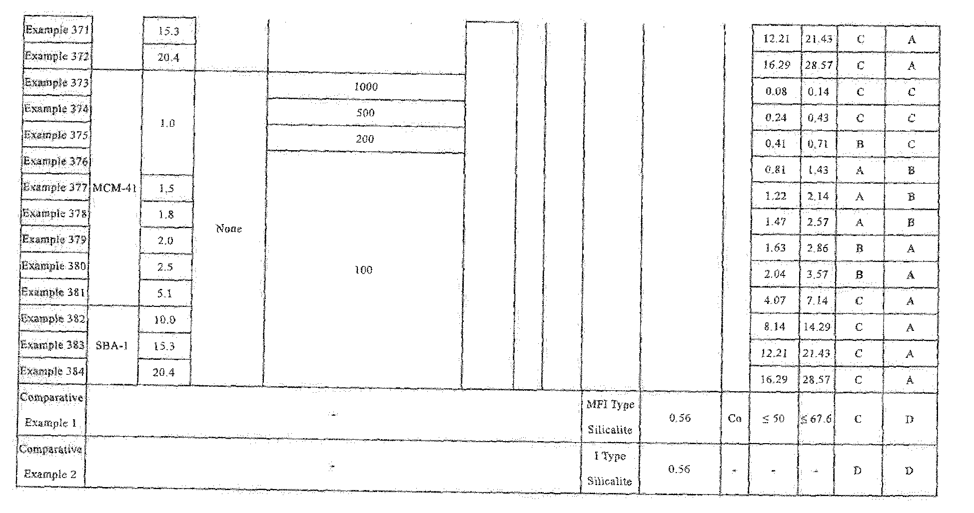
- As can be seen from Tables 1 to 8, the structured catalyst (Examples 1 to 384), which was confirmed by cross sectional observation to hold the catalytic substance inside the support was found to exhibit excellent catalytic activity in the CO shift reaction and excellent durability as a catalyst compared to the structured catalyst in which the catalytic substance is simply adhered to the outer surface of the support (Comparative Example 1) or the support without any catalytic substances (Comparative Example 2).
- In addition, the relationship between the amount of metal (mass%) that was embedded in the support of the structured catalyst measured in evaluation [C] above and the catalytic activity of evaluation (1) described above was evaluated. The evaluation method was the same as the evaluation method performed in "(1) catalytic activity" in the [D] "performance evaluation" described above. As a result, in each Example, when the value obtained by converting the added amount of the metal-containing solution added to the precursor material (A) to the ratio of number of atoms Si/M (M = Fe) is from 50 to 200 (the content of the metal element (M) of metal nanoparticles relative to the structured catalyst is from 0.5 to 2.5 mass%), the catalytic activity in the CO shift reaction was found to tend to increase.
- The catalytic activity in the reverse shift reaction was evaluated under the following conditions:
- Of the Examples shown in Table 1 to 8, as a typical example, 70 mg of the structured catalyst in which both the catalytic activity and heat resistance were rated "A" was charged into a normal pressure flow reactor, and the reaction gas (CO2:H2 = 1:2) was fed at SV = 2000 h-1) was fed at SV = 2000 h-1, and a reverse shift reaction was performed under heating at 100 to 800°C. The normal pressure flow reactor was single microreactor (Rx-3050SR, available from Frontier Laboratories Ltd.).
- After completion of the reaction, the generated gas that was collected was analyzed by gas chromatography mass spectrometry (GC/MS) for the composition.. Note that, as the analysis device, TRACE 1310 GC (available from Thermo Fisher Scientific Inc., detector: thermal conductivity detector) was used.
- Furthermore, the product obtained by the reverse shift reaction was confirmed based on the results of the component analysis described above. In this evaluation, the above operations were performed using the catalytic structural bodies obtained in the Examples shown in Table 9, and judgement was performed using the following evaluation criteria.
- When generation of carbon monoxide and water (water vapor) was confirmed at lower than 400°C (in other words, when the reaction initiation temperature was lower than 400°C), the catalytic activity in the reverse shift reaction was judged to be excellent and rated "A", when generation of carbon monoxide and water (water vapor) was confirmed at lower than 600°C (in other words, when the reaction initiation temperature was 400°C or higher and lower than 600°C), the catalytic activity was determined to be good and rated "C", and when generation of carbon monoxide and water (water vapor) was confirmed at 600°C or higher (in other words, when the reaction initiation temperature was 600°C or higher) or no reverse shift reaction occurred, the catalytic activity was determined to be poor (unacceptable) and rated "D".
- Furthermore, in the product obtained by the reverse shift reaction, the presence or absence of generation of methane (CH4) as a by-product was confirmed based on the results of the above-described component analysis. The case where the generation of methane was not confirmed was rated "A", and the case where the generation of methane was confirmed was rated "D". These evaluation results are shown in Table 9.
[Table 9] No. Structured Catalyst Evaluation of CO Shift Reaction Performance Evaluation of Reverse Sift Reaction Performance Support Catalytic Substance DC/DF Catalytic Activity Durability Catalytic Activity Generation of Methane Zeolite-Type Compound Metal Nanoparticles Framework Average Inner Diameter of Channels DF Type Average Particle Size DC (nm) (nm) Example 6 FAU 0.74 Co 1.59 2.14 A A C D Example 7 1.90 2.57 A A C D Example 8 2.11 2.86 A A C D Example 31 MTW 0.61 1.74 2.86 A A C D Example 32 2.18 3.57 A A C D Example 54 MFI 0.56 1.14 2.57 A A C D Example 55 1.60 2.86 A A C D Example 56 2.00 3.57 A A C D Example 79 FER 0.57 1.63 2.86 A A C D Example 80 2.04 3.57 A A C D Example 102 FAU 0.74 Ni 1.90 2.57 A A C D Example 103 2.11 2.86 A A C D Example 104 2.64 3.57 A A C D Example 127 MTW 0.61 1.74 2.86 A A C D Example 128 2.18 3.57 A A C D Example 150 MFI 0.56 1.44 2.57 A A C D Example 151 1.60 2.86 A A C D Example 152 2.00 3.57 A A C D Example 175 FER 0.57 1.63 2.86 A A C D Example 176 2.04 3.57 A A C D Example 198 FAU 0.74 Fe 1.90 2.57 A A C B Example 199 2.11 2.86 A A C B Example 200 2.64 3.57 A A C B Example 223 MTW 0.61 1.74 2.86 A A C B Example 224 2.18 3.57 A A C B Example 246 MFI 0.56 1.44 2.57 A A C B Example 247 1.60 2.86 A A C B Example 248 2.00 3.57 A A C B Example 271 FER 0.57 1.63 2.86 A A C B Example 272 2.04 3.57 A A C B Example 294 FAU 0.74 Cu 1.90 2.57 A A B B Example 295 2.11 2.86 A A B B Example 296 2.64 3.57 A A B B Example 319 MTW 0.61 1.74 2.86 A A B B Example 320 2.18 3.57 A A B B Example 342 MFI 0.56 1.44 2.57 A A B B Example 343 1.60 2.86 A A B B Example 344 2.00 3.57 A A B B Example 367 FER 0.57 1.63 2.86 A A B B Example 368 2.04 3.57 A A B B - As is evident from Table 9, the catalytic structural bodies of each example shown in Table 9 had good catalytic activity in the reverse shift reaction, in particular the catalytic structural bodies of Examples 294, 295, 296, 319, 320, 342, 343, 344, 367 and 368 had excellent catalytic activity in the reverse shift reaction. From this finding, the catalytic structural bodies of the examples shown in Table 9 were found to perform a reverse shift reaction at a lower temperature than prior art, and exhibit excellent catalytic performance. Furthermore, the catalytic structural bodies of Examples 198, 199, 200, 223, 224, 246, 247, 248, 271, 272, 294, 295, 296, 319, 320, 342, 343, 344, 367 and 368 exhibited no generation of methane, which is a by-product, and thus performed more efficient reverse shift reaction.
- On the other hand, although the structured catalyst of Comparative Example 1 in which the catalytic substance was attached only to the outer surface of the support, the catalytic activity in the CO shift reaction was improved compared to the support itself having no catalytic substance of Comparative Example 21, but exhibited inferior durability as a catalyst compared to the catalytic structural bodies of Examples 1 to 384.
- From the above results, it is presumed that that the structured catalyst for CO shift and the structured catalyst for reverse shift according to the present invention exhibit excellent catalytic activity in the CO shift reaction and the reverse shift reaction, and have excellent durability as a catalyst.
- A method for using a structured catalyst for CO shift or reverse shift,
in which the CO shift or reverse shift structural body includes a support of a porous structure composed of a zeolite-type compound and at least one type of metal nanoparticles present in the support,
the support has channels connecting with each other, and
the metal nanoparticles are present in at least an enlarged pore portion of the channels. -
- 1 structured catalyst for CO shift, structured catalyst for reverse shift
- 2 structured catalyst for CO shift, structured catalyst for reverse shift
- 10 Support
- 10a Outer surface
- 11 Channel
- 11a Pore
- 12 Enlarged pore portion
- 20 CO shift catalytic substance, reverse shift catalytic substance
- 30 CO Shift catalytic substance, reverse shift catalytic substance
- DC Average particle size
- DF Average inner diameter
- DE Inner diameter
Claims (30)
- A structured catalyst for CO shift or reverse shift, comprising:a support of a porous structure composed of a zeolite-type compound; andat least one CO shift or reverse shift catalytic substance present in the support, whereinthe support has channels connecting with each other, andthe CO shift or reverse shift catalytic substance is present at least in the channels of the support.
- The structured catalyst for CO shift or reverse shift according to claim 1, wherein
the channels have any one of a one-dimensional pore, a two-dimensional pore, and a three-dimensional pore defined by a framework of the zeolite-type compound and an enlarged pore portion different from any of the one-dimensional pore, the two-dimensional pore, and the three-dimensional pore, and
the CO shift or reverse shift catalytic substance is present at least in the enlarged pore portion. - The structured catalyst for CO shift or reverse shift according to claim 2, wherein the enlarged pore portion causes a plurality of pores constituting any one of the one-dimensional pore, the two-dimensional pore, and the three-dimensional pore to connect with each other.
- The structured catalyst for CO shift or reverse shift according to claim 2 or 3, wherein the CO shift or reverse shift catalytic substance is made of metal nanoparticles.
- The structured catalyst for CO shift or reverse shift according to claim 4, wherein the metal nanoparticles are nanoparticles composed of at least one type of metal or metal oxide selected from the group consisting of cobalt, nickel, iron, and copper.
- The structured catalyst for CO shift or reverse shift according to claim 5, wherein the metal nanoparticles are nanoparticles composed of at least one type of metal or metal oxide selected from the group consisting of cobalt, iron, and copper.
- The structured catalyst for CO shift or reverse shift according to any one of claims 4 to 6, wherein the average particle size of the metal nanoparticles is greater than an average inner diameter of the channels and is less than or equal to the inner diameter of the enlarged pore portion.
- The structured catalyst for CO shift or reverse shift according to any one of claims 4 to 7, wherein a metal element (M) of the metal nanoparticles is contained in an amount from 0.5 mass% to 2.5 mass% based on the structured catalyst for CO shift or reverse shift.
- The structured catalyst for CO shift or reverse shift according to any one of claims 4 to 8, wherein the average particle size of the metal nanoparticles is from 0.08 nm to 30 nm.
- The structured catalyst for CO shift or reverse shift according to claim 9, wherein the average particle size of the metal nanoparticles is from 0.4 nm to 11.0 nm.
- The structured catalyst for CO shift or reverse shift according to any one of claims 4 to 10, wherein the ratio of the average particle size of the metal nanoparticles to the average inner diameter of the channels is from 0.05 to 300.
- The structured catalyst for CO shift or reverse shift according to claim 11, wherein the ratio of the average particle size of the metal nanoparticles to the average inner diameter of the channels is from 0.1 to 30.
- The structured catalyst for CO shift or reverse shift according to claim 12, wherein the ratio of the average particle size of the metal nanoparticles to the average inner diameter of the channels is from 1.4 to 3.6.
- The structured catalyst for CO shift or reverse shift according to any one of claims 2 to 13, wherein the average inner diameter of the channels is from 0.1 nm to 1.5 nm, and the inner diameter of the enlarged pore portion is from 0.5 nm to 50 nm.
- The structured catalyst for CO shift or reverse shift according to any one of claims 1 to 14, further comprising at least one another CO shift or reverse shift catalytic substance held on an outer surface of the support.
- The structured catalyst for CO shift or reverse shift according to claim 15, wherein the content of the at least one CO shift or reverse shift catalytic substance present in the support is greater than that of the at least other one CO shift or reverse shift catalytic substance held on an outer surface of the support.
- The structured catalyst for CO shift or reverse shift according to any one of claims 1 to 16, wherein the zeolite-type compound is a silicate compound.
- A CO shift or reverse shift reactor having the structured catalyst for CO shift or reverse shift described in any one of claims 1 to 17.
- A method for producing a structured catalyst for CO shift or reverse shift, comprising:a calcination step of calcining a precursor material (B) obtained by impregnating a precursor material (A) for obtaining a support of a porous structure composed of zeolite-type compound with a metal-containing solution;a hydrothermal treatment step of hydrothermal-treating a precursor (C) obtained by calcining the precursor material (B); anda reduction treatment step of the hydrothermally treated precursor material (C).
- The method for producing the structured catalyst for CO shift or reverse shift according to claim 19, wherein from 50 to 500 mass% of a non-ionic surfactant is added to the precursor material (A) before the calcination step.
- The method for producing the structured catalyst for CO shift or reverse shift according to claim 19 or 20, wherein the precursor material (A) is impregnated with the metal-containing solution by adding the metal-containing solution to the precursor material (A) in multiple portions prior to the calcination step.
- The method for producing the structured catalyst for CO shift or reverse shift according to any one of claims 19 to 21, wherein in impregnating the precursor material (A) with the metal-containing solution prior to the calcination step, the value obtained by converting the added amount of the metal-containing solution added to the precursor material (A) to the ratio of silicon (Si) constituting the precursor material (A) to the metal element (M) included in the metal-containing solution added to the precursor material (A), a ratio of number of atoms Si/M, is adjusted to from 10 to 1000.
- The method for producing the structured catalyst for CO shift or reverse shift according to claim 19, wherein in the hydrothermal treatment step, the precursor material (C) and a structure directing agent are mixed.
- The method for producing the structured catalyst for CO shift or reverse shift according to claim 19, wherein the hydrothermal treatment step is performed in a basic condition.
- A method for producing carbon dioxide and hydrogen that generates carbon dioxide and hydrogen from carbon monoxide and water using a catalyst,
the catalyst comprising:a support of a porous structure composed of a zeolite-type compound; andat least one type of metal nanoparticles present in the support, whereinthe support has channels connecting with each other, andthe metal nanoparticles include a structured catalyst for CO shift present in at least an enlarged pore portion of the channels. - A method for producing carbon dioxide and hydrogen, wherein carbon dioxide and hydrogen are generated from carbon monoxide and water using the structured catalyst for CO shift described in any one of claims 1 to 17.
- A method for producing carbon dioxide and hydrogen, wherein carbon monoxide and water are converted to carbon dioxide and hydrogen using the CO shift reactor described in claim 18.
- A method of producing carbon monoxide and water that generates carbon monoxide and water from carbon dioxide and hydrogen using a catalyst,
the catalyst comprising:a support of a porous structure composed of a zeolite-type compound; andat least one type of metal nanoparticles present in the support, whereinthe support has channels connecting with each other, andthe metal nanoparticles include a structured catalyst for reverse shift present in at least an enlarged pore portion of the channels. - A method for producing carbon monoxide and water, wherein carbon monoxide and water are generated from carbon dioxide and hydrogen using the structured catalyst for reverse shift described in any one of claims 1 to 17.
- A method for producing carbon monoxide and water, wherein carbon dioxide and hydrogen are converted to carbon monoxide and water using the reverse shift reactor described in claim 18.
Applications Claiming Priority (2)
| Application Number | Priority Date | Filing Date | Title |
|---|---|---|---|
| JP2017108630 | 2017-05-31 | ||
| PCT/JP2018/021086 WO2018221698A1 (en) | 2017-05-31 | 2018-05-31 | Co shift or reverse shift catalyst structure and production method thereof, co shift or reverse shift reaction device, production method of carbon dioxide and hydrogen, and production method of carbon monoxide and water |
Publications (2)
| Publication Number | Publication Date |
|---|---|
| EP3632542A1 true EP3632542A1 (en) | 2020-04-08 |
| EP3632542A4 EP3632542A4 (en) | 2021-01-06 |
Family
ID=64455848
Family Applications (1)
| Application Number | Title | Priority Date | Filing Date |
|---|---|---|---|
| EP18809577.2A Withdrawn EP3632542A4 (en) | 2017-05-31 | 2018-05-31 | DIRECT OR REVERSE CONVERSION CATALYST STRUCTURE AND PRODUCTION PROCESS OF THE SAME, DIRECT OR REVERSE REACTION DEVICE, PROCESS FOR THE PRODUCTION OF CARBON DIOXIDE AND HYDROGEN, AND PROCESS FOR THE PRODUCTION OF CARBON MONOXIDE AND WATER |
Country Status (5)
| Country | Link |
|---|---|
| US (1) | US11666894B2 (en) |
| EP (1) | EP3632542A4 (en) |
| JP (1) | JP7306990B2 (en) |
| CN (1) | CN110691646A (en) |
| WO (1) | WO2018221698A1 (en) |
Families Citing this family (20)
| Publication number | Priority date | Publication date | Assignee | Title |
|---|---|---|---|---|
| JP7316934B2 (en) | 2017-05-31 | 2023-07-28 | 古河電気工業株式会社 | Hydrodesulfurization catalyst structure, hydrodesulfurization apparatus equipped with the catalyst structure, and method for producing hydrodesulfurization catalyst structure |
| CN110678259A (en) | 2017-05-31 | 2020-01-10 | 国立大学法人北海道大学 | Functional structure and method for manufacturing functional structure |
| WO2018221707A1 (en) | 2017-05-31 | 2018-12-06 | 古河電気工業株式会社 | Steam reforming catalyst structure, reforming device provided with said steam reforming catalyst structure, and production method of steam reforming catalyst structure |
| WO2018221693A1 (en) | 2017-05-31 | 2018-12-06 | 国立大学法人北海道大学 | Functional structure and production method for functional structure |
| WO2018221706A1 (en) | 2017-05-31 | 2018-12-06 | 古河電気工業株式会社 | Methanol reforming catalyst structure, methanol reforming device, production method for methanol reforming catalyst structure, and production method for at least one of olefins and aromatic hydrocarbons |
| EP3632554A4 (en) | 2017-05-31 | 2021-04-21 | Furukawa Electric Co., Ltd. | EXHAUST GAS PURIFICATION OXIDATION CATALYST STRUCTURE AND PRODUCTION PROCESS, VEHICLE EXHAUST GAS TREATMENT DEVICE, CATALYST MOLDED BODY AND GAS PURIFICATION PROCESS. |
| CN110730687A (en) | 2017-05-31 | 2020-01-24 | 古河电气工业株式会社 | Catalyst structure for catalytic cracking or hydrodesulfurization, catalytic cracking apparatus and hydrodesulfurization apparatus having the catalyst structure, and method for producing a catalyst structure for catalytic cracking or hydrodesulfurization |
| EP3632548A4 (en) | 2017-05-31 | 2021-03-03 | National University Corporation Hokkaido University | FUNCTIONAL STRUCTURE AND PROCESS FOR THE PRODUCTION OF FUNCTIONAL STRUCTURE |
| CN110678258A (en) | 2017-05-31 | 2020-01-10 | 国立大学法人北海道大学 | Functional structure and method for producing functional structure |
| CN113164944A (en) * | 2018-12-03 | 2021-07-23 | 国立大学法人北海道大学 | Functional structure |
| CN113164942A (en) | 2018-12-03 | 2021-07-23 | 国立大学法人北海道大学 | Functional structure |
| JP2021070616A (en) * | 2019-11-01 | 2021-05-06 | 株式会社日立製作所 | Apparatus for producing carbon monoxide, chemical plant and plant |
| JP7462899B2 (en) * | 2020-03-12 | 2024-04-08 | 古河電気工業株式会社 | Mobile Reaction System |
| JP7822928B2 (en) * | 2020-03-31 | 2026-03-03 | 大阪瓦斯株式会社 | Method for producing reverse water gas shift catalyst |
| EP4130342A4 (en) * | 2020-03-31 | 2025-03-12 | Osaka Gas Co., Ltd. | ELECTROLYTIC CELL UNIT, ELECTROLYTIC CELL DEVICE, HYDROCARBON PREPARATION SYSTEM, AND METHODS OF MAKING AND USING AN ELECTROLYTIC CELL UNIT |
| JP2021186770A (en) | 2020-06-01 | 2021-12-13 | 古河電気工業株式会社 | Catalyst structure for synthetic gas manufacture, synthetic gas manufacturing apparatus and manufacturing method of catalyst structure for synthetic gas manufacture |
| WO2022210983A1 (en) * | 2021-03-31 | 2022-10-06 | 古河電気工業株式会社 | Catalyst structure for synthesis gas production, synthesis gas production device, and method for producing catalyst structure for synthesis gas production |
| CN113145098A (en) * | 2021-05-14 | 2021-07-23 | 丽水学院 | Ordered mesoporous metal oxide catalyst with single-pore structure and preparation method thereof |
| CN115569663B (en) * | 2021-06-21 | 2023-10-20 | 中国石油化工股份有限公司 | Preparation method of novel sulfur-tolerant shift catalyst |
| CN116251614A (en) * | 2023-05-09 | 2023-06-13 | 山东秋水化学科技有限公司 | Catalyst for CO conversion reaction and preparation method thereof |
Family Cites Families (120)
| Publication number | Priority date | Publication date | Assignee | Title |
|---|---|---|---|---|
| US3898180A (en) | 1970-07-23 | 1975-08-05 | Ici Ltd | Catalyst pellet |
| JPS5746925A (en) | 1980-09-03 | 1982-03-17 | Res Assoc Petroleum Alternat Dev<Rapad> | Preparation of hydrocarbon |
| US4552855A (en) | 1982-12-30 | 1985-11-12 | Ozin Geoffrey A | Metal zeolite catalyst preparation |
| US5026673A (en) | 1989-06-23 | 1991-06-25 | University Of Delaware | Stable zeolite-supported transition metal catalysts, methods for making them, and uses thereof |
| JP2771321B2 (en) | 1990-11-09 | 1998-07-02 | 日本碍子株式会社 | Exhaust gas purifying catalyst composition, exhaust gas purifying catalyst and method for producing the same |
| US5275720A (en) | 1990-11-30 | 1994-01-04 | Union Oil Company Of California | Gasoline hydrocracking catalyst and process |
| US5236575A (en) | 1991-06-19 | 1993-08-17 | Mobil Oil Corp. | Synthetic porous crystalline mcm-49, its synthesis and use |
| JPH0549943A (en) | 1991-08-20 | 1993-03-02 | Sakai Chem Ind Co Ltd | Oxidizing catalyst |
| JPH06142456A (en) | 1992-11-08 | 1994-05-24 | Sekiyu Sangyo Kasseika Center | Method for removing nox in exhaust gas |
| JPH0796195A (en) | 1993-09-29 | 1995-04-11 | Hino Motors Ltd | Exhaust gas purification catalyst |
| JP2006021994A (en) | 1993-12-28 | 2006-01-26 | Toto Ltd | Method of manufacturing multifunctional material having photocatalytic function |
| US5849652A (en) | 1994-03-14 | 1998-12-15 | Northeastern University | Metal containing catalysts and methods for making same |
| JPH08155303A (en) | 1994-12-01 | 1996-06-18 | Toyota Central Res & Dev Lab Inc | Exhaust gas purifying catalyst carrier, exhaust gas purifying catalyst, method for manufacturing exhaust gas purifying catalyst carrier, and exhaust gas purifying method |
| US5994603A (en) | 1996-05-29 | 1999-11-30 | Exxon Chemical Patents Inc. | Methylation of toluene to para-xylene |
| CN1223602A (en) | 1996-05-29 | 1999-07-21 | 埃克森化学专利公司 | Metal-containing zeolite catalysts, their preparation and their use in hydrocarbon conversion |
| EA199801059A1 (en) | 1996-05-29 | 1999-06-24 | Эксон Кемикэл Пейтентс Инк. | METAL CONTAINING ZEOLITE CATALYST, ITS OBTAINING AND APPLICATION IN THE CONVERSION OF HYDROCARBONS |
| JPH11151440A (en) | 1997-07-18 | 1999-06-08 | Tokyo Gas Co Ltd | Catalyst for decomposing and removing nitrogen oxides and method for decomposing and removing nitrogen oxides |
| JPH1133412A (en) | 1997-07-23 | 1999-02-09 | Unitika Ltd | Production of metal-supporting catalyst |
| JP2000197822A (en) | 1999-01-08 | 2000-07-18 | Tokyo Gas Co Ltd | Catalyst for decomposing and removing nitrogen oxides and method for decomposing and removing nitrogen oxides |
| JP3897143B2 (en) | 1999-05-11 | 2007-03-22 | 富士電機ホールディングス株式会社 | Reforming apparatus, starting method thereof, and fuel cell power generation apparatus |
| US6930219B2 (en) | 1999-09-07 | 2005-08-16 | Abb Lummus Global Inc. | Mesoporous material with active metals |
| US7074373B1 (en) * | 2000-11-13 | 2006-07-11 | Harvest Energy Technology, Inc. | Thermally-integrated low temperature water-gas shift reactor apparatus and process |
| FR2819432B1 (en) | 2001-01-18 | 2003-04-11 | Rhodia Chimie Sa | MESOSTRUCTURE CATALYST INTEGRATING NANOMETRIC PARTICLES |
| JP2002255537A (en) | 2001-02-22 | 2002-09-11 | National Institute Of Advanced Industrial & Technology | Solid acid catalyst |
| JP2002336704A (en) | 2001-05-18 | 2002-11-26 | Masaru Ichikawa | Catalyst for aromatization reaction of methane and its preparation method |
| US6881703B2 (en) | 2001-08-08 | 2005-04-19 | Corning Incorporated | Thermally conductive honeycombs for chemical reactors |
| JP2003230838A (en) | 2001-12-06 | 2003-08-19 | Denso Corp | Ceramic catalyst body |
| EP1572579A2 (en) | 2002-12-20 | 2005-09-14 | Honda Giken Kogyo Kabushiki Kaisha | Noble metal-free nickel catalyst formulations for hydrogen generation |
| JP2005170903A (en) | 2003-12-15 | 2005-06-30 | Idemitsu Kosan Co Ltd | Method for producing bicyclo [2.2.1] heptane derivative |
| JP4334336B2 (en) | 2003-12-26 | 2009-09-30 | 株式会社フジクラ | Light switch |
| WO2005083013A1 (en) | 2004-01-30 | 2005-09-09 | Millennium Chemicals | Coating composition having surface depolluting properties |
| JP4469975B2 (en) | 2004-03-23 | 2010-06-02 | 国立大学法人広島大学 | Photocatalyst composite and organic substance conversion method using the same |
| JP5194249B2 (en) | 2004-03-29 | 2013-05-08 | 国立大学法人広島大学 | Composite porous body, method for producing the same, and organic substance conversion method using the same |
| US20090325790A1 (en) * | 2004-06-17 | 2009-12-31 | Yale University | Size-controllable transition metal clusters in mcm-41 for improving chemical catalysis |
| WO2006099573A1 (en) * | 2005-03-16 | 2006-09-21 | Fuelcor Llc | Systems, methods, and compositions for production of synthetic hydrocarbon compounds |
| EP1866083B1 (en) | 2005-03-24 | 2021-06-30 | University of Regina | Nickel on Ceria/Zirconia catalyst |
| FR2886636B1 (en) | 2005-06-02 | 2007-08-03 | Inst Francais Du Petrole | INORGANIC MATERIAL HAVING METALLIC NANOPARTICLES TRAPPED IN A MESOSTRUCTURED MATRIX |
| CN100392047C (en) | 2005-06-09 | 2008-06-04 | 中国科学院大连化学物理研究所 | A method for producing olefins by catalytic oxidation cracking of petroleum hydrocarbons |
| JP5042827B2 (en) | 2005-06-29 | 2012-10-03 | イビデン株式会社 | Honeycomb structure |
| WO2007023558A1 (en) | 2005-08-26 | 2007-03-01 | Suminoe Textile Co., Ltd. | Tungsten oxide photocatalyst, process for producing the same, and fiber cloth having deodorizing/antifouling function |
| MXPA05009283A (en) | 2005-08-31 | 2007-02-27 | Mexicano Inst Petrol | PROCEDURE FOR THE PREPARATION OF A CATALYTIC COMPOSITION FOR THE HYDROPROCESSING OF PETROLEUM FRACTIONS. |
| JP4879574B2 (en) | 2005-09-16 | 2012-02-22 | 旭化成ケミカルズ株式会社 | Process for producing ethylene and propylene |
| JP5025477B2 (en) | 2005-09-16 | 2012-09-12 | 旭化成ケミカルズ株式会社 | Process for producing ethylene and propylene |
| JP2007130525A (en) | 2005-11-08 | 2007-05-31 | Nissan Motor Co Ltd | Inclusion catalyst and production method thereof |
| JP5076377B2 (en) | 2006-07-03 | 2012-11-21 | トヨタ自動車株式会社 | Exhaust gas purification catalyst |
| US7879749B2 (en) | 2006-08-15 | 2011-02-01 | Battelle Energy Alliance, Llc | Methods of using structures including catalytic materials disposed within porous zeolite materials to synthesize hydrocarbons |
| US7592291B2 (en) * | 2006-08-15 | 2009-09-22 | Batelle Energy Alliance, Llc | Method of fabricating a catalytic structure |
| CN101130466B (en) | 2006-08-23 | 2011-05-04 | 中国科学院大连化学物理研究所 | Method of start working of fluidization catalytic reaction device for preparing low carbon olefinic hydrocarbon |
| US8993468B2 (en) | 2007-05-24 | 2015-03-31 | Saudi Basic Industries Corporation | Catalyst for conversion of hydrocarbons, process of making and process of using thereof—Ge zeolites |
| CN101362959B (en) | 2007-08-09 | 2012-09-05 | 中国石油化工股份有限公司 | Catalytic conversion method for preparing propone and high-octane number gasoline |
| JP4943516B2 (en) | 2008-02-01 | 2012-05-30 | 島津システムソリューションズ株式会社 | Silver-titanium oxide-zeolite adsorptive decomposition material |
| FR2929264B1 (en) | 2008-03-31 | 2010-03-19 | Inst Francais Du Petrole | INORGANIC MATERIAL FORM OF SPHERICAL PARTICLES OF SPECIFIC SIZE AND HAVING METALLIC NANOPARTICLES TRAPPED IN A MESOSTRUCTURED MATRIX |
| JP2009255014A (en) | 2008-04-21 | 2009-11-05 | Mitsubishi Chemicals Corp | Catalyst for producing olefin from methanol |
| KR101242254B1 (en) | 2008-06-10 | 2013-03-11 | 미쓰이 가가쿠 가부시키가이샤 | Method for producing an alkylated aromatic compound and method for producing phenol |
| JP4639247B2 (en) | 2008-07-23 | 2011-02-23 | 石油資源開発株式会社 | Hydrocarbon reforming catalyst, process for producing the same, and process for producing synthesis gas using the same |
| JP2010099638A (en) | 2008-10-27 | 2010-05-06 | Nissan Motor Co Ltd | Catalyst, catalyst for purifying exhaust gas, and method for manufacturing the catalyst |
| WO2010097108A1 (en) * | 2009-02-27 | 2010-09-02 | Haldor Topsøe A/S | Process for the preparation of hybrid zeolite or zeolite-like materials |
| US9187702B2 (en) | 2009-07-01 | 2015-11-17 | Chevron U.S.A. Inc. | Hydroprocessing catalyst and method of making the same |
| IN2012DN00813A (en) | 2009-07-30 | 2015-06-26 | Mitsubishi Chem Corp | |
| JP2012250133A (en) | 2009-09-30 | 2012-12-20 | Toto Ltd | Photocatalyst-coated object, and photocatalyst coating liquid therefor |
| CN102665896A (en) | 2009-11-27 | 2012-09-12 | 株式会社村田制作所 | Anti-shift reaction catalyst, and process for production of synthetic gas using same |
| WO2011128968A1 (en) | 2010-04-12 | 2011-10-20 | 株式会社メタルテック | Photocatalytic coating material |
| US8772529B2 (en) | 2010-06-10 | 2014-07-08 | Ube Industries, Ltd | Catalyst for alkylation and process for producing alkylaromatic hydrocarbon compound using the catalyst |
| US20120042631A1 (en) | 2010-08-20 | 2012-02-23 | Gm Global Technology Operations, Inc. | Catalyst materials for ammonia oxidation in lean-burn engine exhaust |
| US8539760B2 (en) | 2010-09-14 | 2013-09-24 | GM Global Technology Operations LLC | Catalyst materials for NOx oxidation in an exhaust aftertreatment system that uses passive ammonia SCR |
| FR2969513B1 (en) | 2010-12-22 | 2013-04-12 | IFP Energies Nouvelles | PROCESS FOR THE PREPARATION OF A SPHERICAL MATERIAL HIERARCHISED POROSITY COMPRISING METALLIC PARTICLES PIEGEES IN A MESOSTRUCTURED MATRIX |
| JP5552067B2 (en) | 2011-01-26 | 2014-07-16 | 住友ゴム工業株式会社 | Synthetic system, rubber chemicals for tire, synthetic rubber for tire and pneumatic tire |
| BR112012030796A2 (en) | 2011-01-26 | 2016-11-01 | Sumitomo Rubber Iindustries Ltd | synthesis system, chemical rubber for tires, synthetic rubber for tires, and pneumatic |
| JP2012160394A (en) | 2011-02-02 | 2012-08-23 | Sony Corp | Method for producing oxide semiconductor layer |
| JP2012170951A (en) | 2011-02-24 | 2012-09-10 | Kyushu Univ | Photocatalyst-adsorbent composite powder |
| JP2012210557A (en) | 2011-03-30 | 2012-11-01 | Panasonic Corp | Water-repellent photocatalytic composition and water-repellent photocatalytic coating film |
| CN102247887B (en) | 2011-05-20 | 2013-03-06 | 汕头大学 | Preparation method of high-efficiency and low-load methane aromatization catalyst |
| CN103648643B (en) | 2011-06-05 | 2016-10-05 | 庄信万丰股份有限公司 | PGM catalysts for exhaust gas treatment |
| CA2851988C (en) * | 2011-10-21 | 2019-05-21 | Igtl Technology Ltd | Methods of preparation and forming supported active metal catalysts and precursors |
| GB201118228D0 (en) * | 2011-10-21 | 2011-12-07 | Ingen Gtl Ltd | Methods of preparation and forming supported active metal catalysts and precursors |
| JP6061872B2 (en) | 2012-01-31 | 2017-01-18 | 国立研究開発法人科学技術振興機構 | Titanium oxide mesocrystal |
| WO2013123299A1 (en) | 2012-02-17 | 2013-08-22 | Kior, Inc. | Mesoporous zeolite-containing catalysts for the thermoconversion of biomass and for upgrading bio-oils |
| JP5972678B2 (en) | 2012-06-14 | 2016-08-17 | 三菱化学株式会社 | Synthesis gas production catalyst and synthesis gas production method |
| CN103663490B (en) | 2012-09-26 | 2016-04-20 | 中国科学院大连化学物理研究所 | A kind of SAPO-34 molecular sieve and synthetic method thereof |
| US9573121B2 (en) | 2012-11-08 | 2017-02-21 | Rive Technology, Inc. | Mesoporous zeolite catalyst supports |
| JP5762386B2 (en) | 2012-11-28 | 2015-08-12 | 株式会社日立製作所 | Shift catalyst, gas purification method and gas purification equipment for coal gasification plant |
| WO2014083772A1 (en) | 2012-11-30 | 2014-06-05 | 国立大学法人広島大学 | Method for producing metal nanoparticle complex, and metal nanoparticle complex produced by said method |
| US10137438B2 (en) | 2013-02-09 | 2018-11-27 | Indian Oil Corporation Limited | Hydroprocessing catalyst composition and process thereof |
| KR102202084B1 (en) | 2013-02-21 | 2021-01-13 | 에네오스 가부시키가이샤 | Method for producing single-ring aromatic hydrocarbons |
| EP2962754B1 (en) | 2013-02-27 | 2021-04-07 | Mitsubishi Heavy Industries Engineering, Ltd. | Method of producing co shift catalyst |
| KR102221550B1 (en) | 2013-03-22 | 2021-03-02 | 삼성전자주식회사 | Nickel catalysts for reforming hydrocarbons |
| WO2014178283A1 (en) | 2013-05-01 | 2014-11-06 | 国立大学法人山梨大学 | Production method for fine metal particles, production method for fuel cell electrode catalyst, supported fine metal particle catalyst, and fuel cell electrode catalyst |
| EP3016741B1 (en) * | 2013-07-05 | 2020-07-01 | Danmarks Tekniske Universitet | Method for producing zeolites and zeotypes |
| CN104650291B (en) | 2013-11-19 | 2018-02-02 | 中国石油天然气股份有限公司 | Method for preparing reinforced styrene-butadiene rubber by using olefin metathesis catalyst |
| CN104774639A (en) | 2014-01-13 | 2015-07-15 | 通用电气公司 | Hydrocarbon cracking method and hydrocarbon cracking apparatus |
| JP6234297B2 (en) | 2014-03-27 | 2017-11-22 | 株式会社タカギ | Zeolite compact and method for producing the same |
| EP3129138B1 (en) | 2014-04-10 | 2020-07-01 | Danmarks Tekniske Universitet | A general method to incorporate metal nanoparticles in zeolites and zeotypes |
| JP6303850B2 (en) | 2014-06-18 | 2018-04-04 | 株式会社Ihi | Catalyst production method |
| US9938157B2 (en) | 2014-07-23 | 2018-04-10 | Chevron U.S.A. Inc. | Interzeolite transformation and metal encapsulation in the absence of an SDA |
| JP6604501B2 (en) * | 2014-09-16 | 2019-11-13 | 国立大学法人山梨大学 | Ammonia decomposition catalyst, method for producing the same, and apparatus using the same |
| JP6344764B2 (en) | 2014-09-30 | 2018-06-20 | 国立大学法人山口大学 | Isopropyl alcohol storage method and filler |
| US9682367B2 (en) | 2014-10-22 | 2017-06-20 | King Fahd University Of Petroleum And Minerals | Monolith structure loaded with metal promoted nanozeolites for enhanced propylene selectivity in methanol conversion |
| JP6427387B2 (en) | 2014-10-31 | 2018-11-21 | 地方独立行政法人東京都立産業技術研究センター | Quantum dot compound photocatalyst |
| JP2015165138A (en) | 2015-04-30 | 2015-09-17 | 日野自動車株式会社 | Exhaust gas purification device |
| WO2016181622A1 (en) | 2015-05-12 | 2016-11-17 | 日本曹達株式会社 | Photocatalyst-containing coating liquid and photocatalyst-supporting structure |
| EP3318327A4 (en) | 2015-07-02 | 2019-02-27 | Dalian Institute Of Chemical Physics Chinese Academy of Sciences | CATALYST AND PROCESS FOR THE PREPARATION OF OLEFINE LIGHT DIRECTLY FROM A SYNTHESIS GAS BY A ONE-STEP PROCESS |
| JP6598576B2 (en) | 2015-08-17 | 2019-10-30 | 学校法人東京理科大学 | Laminate and method for producing laminate |
| JP6489990B2 (en) | 2015-09-30 | 2019-03-27 | Jxtgエネルギー株式会社 | Hydrodesulfurization catalyst for hydrocarbon oil and method for producing the same |
| US20180311651A1 (en) | 2015-10-30 | 2018-11-01 | Sabic Global Technologies B.V. | Use of hollow zeolites doped with bimetallic or trimetallic particles for hydrocarbon reforming reactions |
| CN105347359B (en) | 2015-11-27 | 2017-10-03 | 中国石油大学(北京) | A kind of duct includes the synthesis and its application of the zeolite molecular sieve of solid acid |
| JP6651362B2 (en) | 2016-01-20 | 2020-02-19 | 日揮触媒化成株式会社 | Zeolite containing metal particles |
| CN106362787B (en) | 2016-08-06 | 2019-01-08 | 浙江大学 | A kind of preparation method of the immobilized photochemical catalyst of zeolite |
| US11161101B2 (en) | 2017-05-31 | 2021-11-02 | Furukawa Electric Co., Ltd. | Catalyst structure and method for producing the catalyst structure |
| WO2018221693A1 (en) | 2017-05-31 | 2018-12-06 | 国立大学法人北海道大学 | Functional structure and production method for functional structure |
| WO2018221706A1 (en) | 2017-05-31 | 2018-12-06 | 古河電気工業株式会社 | Methanol reforming catalyst structure, methanol reforming device, production method for methanol reforming catalyst structure, and production method for at least one of olefins and aromatic hydrocarbons |
| CN110678259A (en) | 2017-05-31 | 2020-01-10 | 国立大学法人北海道大学 | Functional structure and method for manufacturing functional structure |
| JP7316934B2 (en) | 2017-05-31 | 2023-07-28 | 古河電気工業株式会社 | Hydrodesulfurization catalyst structure, hydrodesulfurization apparatus equipped with the catalyst structure, and method for producing hydrodesulfurization catalyst structure |
| WO2018221704A1 (en) | 2017-05-31 | 2018-12-06 | 古河電気工業株式会社 | Catalyst structure for aromatic hydrocarbon production, aromatic hydrocarbon production device provided with said catalyst structure for aromatic hydrocarbon production, production method of catalyst structure for aromatic hydrocarbon production, and production method of aromatic hydrocarbons |
| EP3632554A4 (en) | 2017-05-31 | 2021-04-21 | Furukawa Electric Co., Ltd. | EXHAUST GAS PURIFICATION OXIDATION CATALYST STRUCTURE AND PRODUCTION PROCESS, VEHICLE EXHAUST GAS TREATMENT DEVICE, CATALYST MOLDED BODY AND GAS PURIFICATION PROCESS. |
| CN110730687A (en) | 2017-05-31 | 2020-01-24 | 古河电气工业株式会社 | Catalyst structure for catalytic cracking or hydrodesulfurization, catalytic cracking apparatus and hydrodesulfurization apparatus having the catalyst structure, and method for producing a catalyst structure for catalytic cracking or hydrodesulfurization |
| EP3632548A4 (en) | 2017-05-31 | 2021-03-03 | National University Corporation Hokkaido University | FUNCTIONAL STRUCTURE AND PROCESS FOR THE PRODUCTION OF FUNCTIONAL STRUCTURE |
| CN110678258A (en) | 2017-05-31 | 2020-01-10 | 国立大学法人北海道大学 | Functional structure and method for producing functional structure |
| WO2018221707A1 (en) | 2017-05-31 | 2018-12-06 | 古河電気工業株式会社 | Steam reforming catalyst structure, reforming device provided with said steam reforming catalyst structure, and production method of steam reforming catalyst structure |
| WO2018221702A1 (en) | 2017-05-31 | 2018-12-06 | 古河電気工業株式会社 | Photocatalyst structure, photocatalyst structure composition, photocatalyst coating material, production method of photocatalyst structure, and decomposition method of aldehydes |
| CN111447995A (en) | 2017-09-29 | 2020-07-24 | 哈佛学院院长及董事 | Enhanced catalytic material with partially embedded catalytic nanoparticles |
-
2018
- 2018-05-31 JP JP2019521326A patent/JP7306990B2/en active Active
- 2018-05-31 WO PCT/JP2018/021086 patent/WO2018221698A1/en not_active Ceased
- 2018-05-31 CN CN201880035803.7A patent/CN110691646A/en active Pending
- 2018-05-31 EP EP18809577.2A patent/EP3632542A4/en not_active Withdrawn
-
2019
- 2019-11-27 US US16/698,579 patent/US11666894B2/en active Active
Also Published As
| Publication number | Publication date |
|---|---|
| US11666894B2 (en) | 2023-06-06 |
| WO2018221698A1 (en) | 2018-12-06 |
| CN110691646A (en) | 2020-01-14 |
| JP7306990B2 (en) | 2023-07-11 |
| JPWO2018221698A1 (en) | 2020-04-02 |
| EP3632542A4 (en) | 2021-01-06 |
| US20200114338A1 (en) | 2020-04-16 |
Similar Documents
| Publication | Publication Date | Title |
|---|---|---|
| US11666894B2 (en) | Structured catalyst for CO shift or reverse shift and method for producing same, CO shift or reverse shift reactor, method for producing carbon dioxide and hydrogen, and method for producing carbon monoxide and water | |
| US20230009052A1 (en) | Structured catalyst for oxidation for exhaust gas purification, method for producing same, automobile exhaust gas treatment device, catalytic molding, and gas purification method | |
| US12030041B2 (en) | Structured catalyst for steam reforming, reforming apparatus provided with structured catalyst for steam reforming, and method for manufacturing structured catalyst for steam reforming | |
| US11648543B2 (en) | Functional structural body and method for making functional structural body | |
| JP7282027B2 (en) | Ammonia decomposition catalyst structure and fuel cell | |
| CN110678261B (en) | Catalyst structure for synthesis gas production, synthesis gas production apparatus provided with the catalyst structure for synthesis gas production, and method for producing a catalyst structure for synthesis gas production | |
| EP3632553A1 (en) | Catalyst structure for aromatic hydrocarbon production, aromatic hydrocarbon production device provided with said catalyst structure for aromatic hydrocarbon production, production method of catalyst structure for aromatic hydrocarbon production, and production method of aromatic hydrocarbons | |
| EP3632550A1 (en) | Functional structure and production method for functional structure | |
| EP3632546A1 (en) | Fischer-tropsch synthesis catalyst structure, production method thereof, production method of liquid hydrocarbons using said catalyst structure, and hydrocarbon production device having said catalyst structures | |
| EP3632552A1 (en) | Ammonia synthesis catalyst structure and production method therefor, ammonia synthesis device and ammonia synthesis method | |
| JP7295615B2 (en) | Catalyst structure for volatile organic substances, method for producing the same, and device for removing volatile organic substances | |
| JP7316766B2 (en) | N2O decomposition catalyst structure, manufacturing method thereof, and N2O removal device having said N2O decomposition catalyst structure | |
| EP3892370A1 (en) | Functional structure precursor and functional structure | |
| JP2018202408A (en) | NOx DECOMPOSITION CATALYST STRUCTURE AND METHOD FOR PRODUCING THE SAME, AND NOx TREATMENT DEVICE AND CATALYST MOLDED BODY | |
| CN113164943B (en) | Catalyst structure for producing synthesis gas, precursor thereof, synthesis gas production apparatus, and method for producing catalyst structure for producing synthesis gas | |
| EP3632540A1 (en) | Hydrogenolysis catalyst structure, hydrogenolysis device provided with said hydrogenolysis catalyst structure, and production method of hydrogenolysis catalyst structure | |
| JP2018202402A (en) | Reduction catalyst structure for automobile and method for producing the same and exhaust gas treatment device for automobile and catalyst molded body | |
| JP2018202412A (en) | Organic hydride dehydrogenation catalyst structure, method for producing the same, and hydrogen production apparatus having the dehydrogenation catalyst structure |
Legal Events
| Date | Code | Title | Description |
|---|---|---|---|
| STAA | Information on the status of an ep patent application or granted ep patent |
Free format text: STATUS: THE INTERNATIONAL PUBLICATION HAS BEEN MADE |
|
| PUAI | Public reference made under article 153(3) epc to a published international application that has entered the european phase |
Free format text: ORIGINAL CODE: 0009012 |
|
| STAA | Information on the status of an ep patent application or granted ep patent |
Free format text: STATUS: REQUEST FOR EXAMINATION WAS MADE |
|
| 17P | Request for examination filed |
Effective date: 20191220 |
|
| AK | Designated contracting states |
Kind code of ref document: A1 Designated state(s): AL AT BE BG CH CY CZ DE DK EE ES FI FR GB GR HR HU IE IS IT LI LT LU LV MC MK MT NL NO PL PT RO RS SE SI SK SM TR |
|
| AX | Request for extension of the european patent |
Extension state: BA ME |
|
| DAV | Request for validation of the european patent (deleted) | ||
| DAX | Request for extension of the european patent (deleted) | ||
| A4 | Supplementary search report drawn up and despatched |
Effective date: 20201207 |
|
| RIC1 | Information provided on ipc code assigned before grant |
Ipc: B01J 37/10 20060101ALI20201201BHEP Ipc: C01B 3/16 20060101ALI20201201BHEP Ipc: C01B 3/48 20060101ALI20201201BHEP Ipc: B01J 29/035 20060101AFI20201201BHEP Ipc: B01J 29/68 20060101ALI20201201BHEP Ipc: B01J 29/46 20060101ALI20201201BHEP Ipc: B01J 35/00 20060101ALI20201201BHEP Ipc: B01J 29/76 20060101ALI20201201BHEP |
|
| STAA | Information on the status of an ep patent application or granted ep patent |
Free format text: STATUS: EXAMINATION IS IN PROGRESS |
|
| 17Q | First examination report despatched |
Effective date: 20230710 |
|
| STAA | Information on the status of an ep patent application or granted ep patent |
Free format text: STATUS: THE APPLICATION IS DEEMED TO BE WITHDRAWN |
|
| 18D | Application deemed to be withdrawn |
Effective date: 20251202 |