EP3632201B1 - Unabhängiges luftgesteuertes sieb - Google Patents
Unabhängiges luftgesteuertes sieb Download PDFInfo
- Publication number
- EP3632201B1 EP3632201B1 EP19200834.0A EP19200834A EP3632201B1 EP 3632201 B1 EP3632201 B1 EP 3632201B1 EP 19200834 A EP19200834 A EP 19200834A EP 3632201 B1 EP3632201 B1 EP 3632201B1
- Authority
- EP
- European Patent Office
- Prior art keywords
- fluid
- manifold
- sieve
- cross members
- sieve assembly
- Prior art date
- Legal status (The legal status is an assumption and is not a legal conclusion. Google has not performed a legal analysis and makes no representation as to the accuracy of the status listed.)
- Active
Links
Images




Classifications
-
- A—HUMAN NECESSITIES
- A01—AGRICULTURE; FORESTRY; ANIMAL HUSBANDRY; HUNTING; TRAPPING; FISHING
- A01F—PROCESSING OF HARVESTED PRODUCE; HAY OR STRAW PRESSES; DEVICES FOR STORING AGRICULTURAL OR HORTICULTURAL PRODUCE
- A01F12/00—Parts or details of threshing apparatus
- A01F12/48—Air conduits or blowers for grain
-
- A—HUMAN NECESSITIES
- A01—AGRICULTURE; FORESTRY; ANIMAL HUSBANDRY; HUNTING; TRAPPING; FISHING
- A01F—PROCESSING OF HARVESTED PRODUCE; HAY OR STRAW PRESSES; DEVICES FOR STORING AGRICULTURAL OR HORTICULTURAL PRODUCE
- A01F12/00—Parts or details of threshing apparatus
- A01F12/44—Grain cleaners; Grain separators
- A01F12/444—Fanning means
-
- A—HUMAN NECESSITIES
- A01—AGRICULTURE; FORESTRY; ANIMAL HUSBANDRY; HUNTING; TRAPPING; FISHING
- A01F—PROCESSING OF HARVESTED PRODUCE; HAY OR STRAW PRESSES; DEVICES FOR STORING AGRICULTURAL OR HORTICULTURAL PRODUCE
- A01F12/00—Parts or details of threshing apparatus
- A01F12/44—Grain cleaners; Grain separators
- A01F12/446—Sieving means
-
- A—HUMAN NECESSITIES
- A01—AGRICULTURE; FORESTRY; ANIMAL HUSBANDRY; HUNTING; TRAPPING; FISHING
- A01F—PROCESSING OF HARVESTED PRODUCE; HAY OR STRAW PRESSES; DEVICES FOR STORING AGRICULTURAL OR HORTICULTURAL PRODUCE
- A01F12/00—Parts or details of threshing apparatus
- A01F12/44—Grain cleaners; Grain separators
- A01F12/446—Sieving means
- A01F12/448—Sieve adjusting means
Definitions
- the present disclosure relates to a sieve of a harvesting machine, and in particular, to a sieve that implements air flow to sieve harvested crop.
- Combine harvesters are used in agriculture for harvesting crops which are gathered from the field, threshed-out, and separated.
- the crops obtained by threshing and separating are subsequently freed from undesired crop residues by a cleaning process.
- the cleaning process often includes a blower, which acts on sieves that move back and forth.
- lighter particles such as chaff and the like, are separated from the grain by the air flow and the grain falls through the sieves and is taken to a grain tank.
- Many combine harvesters utilize an upper sieve placed above a lower sieve.
- the upper sieves are often loaded on their front end with a mixture of grain and undesired crop debris, which reach the sieve via a falling stage.
- air flow often directs the undesired crop debris toward the back while the grain is taken to the grain tank.
- the air flow leads to a separation between the grain and impurities so that most of the grain reaches the sieve further in front than the lighter impurities, carried back by the air flow.
- a usual sieve for a combine comprises a rectangular frame in which a plurality of louvers is mounted, adjustable by a longitudinal adjusting rod rotating the louvers around their longitudinal axis.
- the entire sieve is in operation of the combine provided with an air flow from the bottom by a blower.
- a sieve for a harvester has a plurality of louvers and a plurality of cross members adjacent to each one of the plurality of louvers.
- Each of the cross members has a fluid channel that directs a fluid through the plurality of louvers.
- One embodiment includes a controller that selectively provides fluid to the fluid channels of each of the plurality of cross members.
- the controller independently controls the flow rate of the fluid provided to each of the fluid channels of each of the plurality of cross members.
- Another embodiment includes a manifold coupled to each of the plurality of cross members.
- the manifold is positioned along a substantially central portion of the plurality of cross members.
- the manifold is coupled to the harvester.
- the plurality of louvers and the plurality of cross members do not substantially move relative to a frame of the harvester during a harvest operation.
- FIG. 1 an embodiment of a harvester or agricultural combine 10 is shown with a chassis or frame 12 with one or more ground engaging mechanism such as wheels 14 which are in contact with the underlying surface or ground. Wheels 14 are coupled to the frame 12 and are used for a forward propulsion of the combine 10 in a forward operating or travelling direction. The forward operating direction is to the left in Fig. 1 .
- the operation of the combine 10 is controlled from an operator's cab 16.
- the operator's cab 16 may include any number of controls (not shown) for controlling the operation of the combine 10.
- a cutting head 18 is disposed at a forward end of the combine 10 and is used in order to harvest crop such as corn and to conduct it to a slope conveyor 20.
- the harvested crop is conducted by a guide drum 22 from the slope conveyor 20.
- the guide drum 22 guides the harvested crop through an inlet transition section 24 to an axial harvested crop processing arrangement 26, as shown in Fig. 1 .
- the harvested crop processing arrangement 26 may include a rotor housing 34 and a rotor 36 arranged therein.
- the rotor 36 includes a hollow drum 38 to which crop processing elements are fastened for a charging section 40, a threshing section 42, and a separating section 44.
- the charging section 40 is arranged at the front end of the axial harvested crop processing arrangement 26.
- the threshing section 42 and the separating section 44 are located downstream in the longitudinal direction and to the rear of the charging section 40.
- the drum 38 may be in the form of a truncated cone located in the charging section 40.
- the threshing section 42 may include a forward section in the form of a truncated cone and a cylindrical rear section.
- the cylindrical separating section 44 of the drum 38 is located at the rear or end of the axial harvested crop processing unit 26.
- a tangential threshing drum with a following axial threshing section or a straw chopper could also be used.
- Corn, chaff, and the like that fall through a thresher basket associated with the threshing section 42 and through a separating grate associated with the separating section 44 may be directed to a clean crop routing assembly 28 with a blower 46 and sieves 48, 50 with louvers.
- the sieves 48, 50 can be oscillated in a fore-and-aft direction.
- the clean crop routing assembly 28 removes the chaff and guides the clean corn over a screw conveyor 52 to an elevator for clean corn (not shown).
- the elevator for clean corn deposits the clean corn in a corn tank 30, as shown in Fig. 1 .
- the clean corn in the corn tank 30 can be unloaded by means of an unloading screw conveyor 32 to a corn wagon, trailer, or truck (not shown).
- Harvested crop remaining at the lower end of the lower sieve 50 is again transported to the harvested crop processing arrangement 26 by a screw conveyor 54 and an overhead conveyor (not shown).
- the harvested crop residue delivered at the upper end of the upper sieve 48 that consist essentially of chaff and small straw particles may be conveyed by means of an oscillating sheet conveyor 56 to the rear and to a lower inlet 58 of a crop debris routing assembly 60.
- the aforementioned blower 46 produces an air flow that carries much of the chaff and small particles to the rear of the combine and to the crop debris routing assembly 60.
- the blower 46 is capable of providing three or more air paths inside the combine.
- a first air or flow path may be through a front portion of the combine 10.
- a second air or flow path may be above the lower sieve 50 and below the upper sieve 48 or chaffer.
- a third air or flow path may be below the lower sieve 50. All three air or flow paths fill the combine body and can create pressurized air flow to pick up and carry straw, grain, and other residue or particles to the rear of the combine 10.
- Threshed-out straw leaving the separating section 44 is ejected through an outlet 62 from the harvested crop processing arrangement 26 and conducted to an ejection drum 64.
- the ejection drum 64 or discharge beater, interacts with a sheet 66 arranged underneath it to eject the straw to the rear, and the grain and MOG is directed through the clean crop routing assembly 28.
- a wall 68 is located to the rear of the ejection drum 64. The wall 68 guides the straw into an upper inlet 70 of the crop debris routing assembly 60.
- the crop debris routing assembly 60 may include a housing 72 (i.e., chopper housing) with a rotor 74 arranged therein that can rotate in a counterclockwise direction about an axis extending horizontally and transverse to the direction of operation.
- the rotor 74 may include a plurality of chopper knives 76, pendulously suspended in pairs and distributed around the circumference of the rotor 74, that interact with opposing knives 78, which are fixed to the housing 72.
- Two impeller blowers 82 arranged side by side alongside each other, may be provided downstream of an outlet 80 of the crop debris routing assembly 60. Only a single blower 82 is shown in Fig. 1 .
- the impeller blowers 82 may include a number of impeller blades 84, each of which is connected rigidly to an upper circular disk 86, that can rotate about central axes 88.
- the disks 86 with the impeller blades 84 that extend radially can be rotatably driven by a hydraulic motor 90 that is attached above a bottom sheet 102 which is connected with the housing 72 of the crop debris routing assembly 60.
- the impeller blades 84 are connected to a cylindrical central body 92 that transitions into a cone 94 with a point on its end facing away from the disk 86.
- the impeller blades 84 may be rectangular and the height of the body 92 (without cone 94) may be equal to the height of the impeller blades 84.
- the cross section of the body 92 and the cone 94 may be circular, although it could also have a multifaceted shape.
- the sieve assembly 200 includes a rectangular frame 210 with louvers or plates 212, positioned along rows that are perpendicular to the longitudinal axis of the frame 210.
- the plates 212 are connected with crankshafts 214 and the crankshafts 214 engage a slot 216 defined in an adjusting rod 218.
- the Adjusting rod 218 can move in a longitudinal direction of the sieve assembly 200 with a manual or externally operated drive, so as to adjust the angle of the plates 212 and thus the opening size defined between adjacent plates 212. Adjusting the angle of the plates 212 may alter the distance between the lower side of first plate 212 and the upper side of an adjacent plate 212.
- the angle of the plate 212, and coincidentally the space there between, may be adjustable to adapt to the individual harvesting conditions, such as grain size, lateral slope, and throughput among other things.
- the plates 212 are cut in an undulating manner on their back ends and are also curved in an undulating manner in the transverse direction of longitudinal axis.
- FIG. 3 which shows a side view of a conventional adjusting rod 218, and in FIG. 4 , which shows a longitudinal section through a conventional sieve assembly 200
- the plates 212 of the sieve assembly 200 have substantially the same spacing along the longitudinal axis.
- the sieve assembly 200 may typically be moved in a cyclic pattern relative to the frame 12 to disturb the grain and MOG mixture to separate the clean grain from the MOG along the sieve.
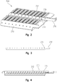
- the sieve assembly 500 may have a plurality of cross members 502 that are substantially perpendicular to the longitudinal axis of the combine 10.
- Each of the plurality of cross member 502 may have a cross member channel 504 defined therein and have at least one orifice 506 that directs fluid out of the cross member 502 and past one or more plurality of louvers 508 in a discharge direction 510.
- the cross member channel 504 defined in each of the plurality of cross members 502 may be selectively fluidly coupled to a manifold 512 by a fluid channel valve 514.
- the manifold 512 may be selectively fluidly coupled to a fluid source 516, such as a blower or the like, through a manifold valve 518. Any one or more of the fluid channel valves 514 and the manifold valve 518 may be controlled by a controller 702 to selectively provide fluid from the fluid source 516, into the manifold 512, into the cross member channels 504 defined by the cross members 502, and out the corresponding orifices 506 in the discharge direction 510.
- a fluid source 516 such as a blower or the like
- the manifold 512 may extend along the longitudinal axis of the combine 10 at a substantially central portion of the plurality of cross members 502. Further, the manifold 512 may be coupled to the frame 12 of the harvester 10 on both a first side 602 and a second side 604. The manifold 512 may be formed of a sufficiently thick material to structurally support the plurality of cross members 502 thereon without substantially deflecting or otherwise bending between the first and second side 602, 604.
- the manifold 512 is coupled to the harvester 10 along a bottom portion or lower chassis of the combine. In another aspect of this disclosure, the manifold 512 may be coupled to the harvester 10 along a top portion under the crop processing arrangement 26.
- the manifold 512 may also form a manifold channel 520 therein.
- the manifold channel 520 may be a channel defined within the manifold 512 to ensure fluid defined therein is selectively directed towards the orifices 506 of the plurality of cross members 502. More specifically, the manifold channel 520 may be constructed walls that are substantially fluid-tight, wherein fluid can only pass into, or out of, the manifold channel 520 through the manifold valve 518 and the one or more fluid channel valves 514. In other words, the manifold 512 may provide both structural support to the sieve assembly 500 while also defining the manifold channel 520 therein.
- Each cross member 502 may similarly provide the cross member channel 504 therein.
- the cross member channel 504 may extend the length of the cross member 502 and provide a channel to fluidly couple each of the orifices 506 to the manifold channel 520 through the corresponding fluid channel valve 514.
- each of the cross members 502 may be formed from a hollow aluminum extrusion that defines the cross member channel 504 therein.
- any known material and method of forming a channel is also considered herein.
- the plurality of louvers 508 may be pivotally coupled to a portion of the corresponding cross member 502 by a louver pivot 524.
- the cross member 502 may provide a structural support to the corresponding louver 508.
- the location of the louver pivot 524 relative to the orifice 506 remains the same regardless of the angular rotation of the louver 508.
- pivotally coupling the louver 508 to the cross member 502 at the louver pivot 524 ensures a consistent relationship between the louver 508 and the corresponding orifice 506. Accordingly, performance of the sieve assembly 500 may be consistently predicted based on the angular orientation of the plurality of louvers 508 relative to the corresponding orifices 506 and the discharge direction 510 of the fluid.
- the plurality of cross members 502 may be formed of any material that is capable of defining the cross member channel 504 therein while simultaneously providing structural support to the corresponding plurality of louvers 508. Accordingly, while aluminum is specifically mentioned above, the plurality of cross members could be formed of any type of material known in the art that is capable of performing as described herein. Further, any number of cross members 502 may be positioned along the manifold 512 and each cross member 502 may have a cross member channel 504 defined therein. Accordingly, while Fig. 6 shows a defined number of cross members 502, this disclosure consider implementing more and less cross members 502 to address different crop types, field conditions, work machine sizes, and any other crop or machine variable that may change depending on the application.
- the plurality of louvers 508 may utilize the same or similar crankshafts 214, slots 216, and adjusting rod 218 described above for the sieve assembly 200 to alter the angle of the plurality of louvers 502.
- any known method for maintaining or adjusting the angle of the plurality of louvers 508 is considered herein.
- the sieve assembly 500 may be intended to remain stationary relative to the frame 12 of the harvester 10. Accordingly, the manifold 512 and cross members 502 coupled thereto may be substantially rigidly mounted at a fore and aft or first and second end 602, 604 to the frame 12 of the harvester 10 and remain substantially stationary relative thereto.
- the controller 702 may be in communication with the fluid source 516, the manifold valve 518, and one or more fluid channel valves 514.
- the fluid source 516 may be a blower 704.
- the blower 704 may be a blower dedicated to the sieve assembly 500 or it may be the blower 46 configured to provide the necessary fluid pressure and flow to the sieve assembly 500.
- the fluid source 516 can be provided by any one or more of a cleaning fan, a dedicated air compressor, an air reservoir, a seed fan, or any other fan, reservoir, or fluid device capable of providing a fluid flow and pressure to the sieve assembly 500.
- the fluid source 516 may be fluidly coupled to the manifold valve 518 via a fluid channel 706.
- the fluid channel 706 may be a hose, pipe, ductwork, or any other fluid directing assembly capable of directing pressurized fluid from the fluid source 516 to the manifold valve 518.
- the manifold valve 518 may be coupled directly to the manifold 512 or located remotely therefrom. If the manifold valve 518 is located remotely from the manifold 512, a manifold connecting hose or other fluid channel may be utilized to direct fluid from the fluid source 516 to the manifold channel 520 when the manifold valve is in an open orientation.
- the manifold valve 518 may have an opened orientation and a closed orientation. In the opened orientation, fluid provided by the fluid source 516 may be fluidly coupled to the manifold channel 520 to thereby be directed through any opened fluid channel valves 514. However, when the manifold valve 518 is in the closed orientation, the pressurized fluid provided from the fluid source 516 may be isolated from the manifold channel 520. Accordingly, the fluid provided from the fluid source 516 will not be fluidly coupled to the cross members 502 of the manifold 512 regardless of the position of the fluid channel valve 514 when the manifold valve 518 is closed.
- the fluid channel valves 514 cannot be fluidly coupled to the fluid source but if the manifold valve 518 is opened the fluid channel valves 514 selectively allow fluid to be discharged from the corresponding orifices 506.
- the manifold valve may be fluidly coupled to the manifold channel 520 as described above and each fluid channel valve 514 may be positioned between the manifold channel 520 and the corresponding cross member channel 504. In this configuration, when the manifold valve 518 is open, each fluid channel valve 514 may selectively allow fluid to be directed out the corresponding orifices 506. Accordingly, in one aspect of this disclosure fluid may be selectively directed from the fluid source to each of the cross members 502 individually via the corresponding fluid channel valve 514.
- the controller 702 may also be in communication with the fluid source 516, the manifold valve 518 and each of the plurality of fluid channel valves 514 via one or more communication link 708.
- the communication link 708 can be any known communication protocol that allows the controller 702 to send commands to the corresponding components and receive feedback therefrom.
- the communication link 708 can be a wire harness that is part of a CAN bus or the like.
- the communication link 708 can be a wireless protocol such as Bluetooth, Wi-Fi, or any other known wireless signal capable of transferring data.
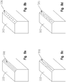
- Fig. 8a may be one example of a cross member 502 that has a substantially continuous orifice 506 across the width of the cross member 502.
- the orifice 506 of Fig. 8a may be positioned on a portion of the cross member 502 so that the discharge direction 510 is away from the cross member 502 and past any louvers 508 coupled thereto (louvers 508 not illustrated in Figs. 8a-8d ).
- the orifice 506 of Fig. 8a may be sized to correlate with the fluid flow and pressure produced by the fluid source 516. More specifically, the orifice 506 may be sized to provide fluid flow in the discharge direction 510 that is sufficient to agitate any grain and MOG positioned along the sieve assembly 500 to thereby separate the grain and MOG.
- Fig. 8b shows another embodiment of the present disclosure wherein a plurality of orifices 506 are defined along the width of the cross member 502.
- each orifice 506 may have substantially the same shape.
- each orifice 506 of Fig. 8b may have a circular cross section with substantially the same diameter.
- the diameter of the orifices 506 of Fig. 8b may be sized to correlate with the fluid flow and pressure produced by the fluid source 516. More specifically, the diameter may be sized to provide fluid flow in the discharge direction 510 that is sufficient to agitate any grain and MOG positioned along the sieve assembly 500 to thereby separate the grain and MOG.
- Fig. 8c may similarly have a plurality of orifices 506 with a circular cross section.
- the orifices of Fig. 8c may have varying diameters across the width of the cross member 502.
- the diameter of the orifices 506 along the central portion of the cross member 502 may be greater than the diameter of the orifices along the edges.
- the diameter of the orifices 506 in the central portion may be smaller than the diameter of the orifices 506 along the edges.
- the diameter of the orifices of Fig. 8c may be altered to manipulate the velocity of the fluid as it exits in the discharge direction 510 to thereby alter the effect of the fluid on the grain and MOG.
- a smaller diameter orifice 506 may provide a higher velocity fluid discharge than a larger orifice 506.
- the higher velocity fluid discharge may be effective in particularly directing the grain and MOG but less capable of handling large volumes of material compared to a larger diameter orifice 506.
- the diameter of the orifice 506 may vary to address the particular discharge profile needed by the application.
- Fig. 8d shows an embodiment having a plurality of orifices 506 that have nozzles positioned thereon. Each nozzle may be on a pivot or the like to selectively alter the discharge direction of each orifice 506 independently from one another. Each nozzle may be repositionable to alter the fluid velocity of fluid discharged therefrom. In one non-exclusive example of the embodiment of Fig. 8d , a user may selectively alter the fluid discharge velocity and direction of each nozzle at each orifice 506 to accommodate the needs of the harvester 10.
- each of the manifold valve 518 and the plurality of fluid channel valves 514 may be capable of varying the flow rate and pressure provided to the corresponding channels 504, 520 from the fluid source 516 to thereby alter the velocity of the fluid as it exits the orifice 506.
- the controller 702 can store operation parameters and instruct the corresponding valves 514, 518 to operate under preset pressures or flow rates.
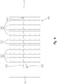
- a valve control chart 900 is illustrated.
- the valve control chart 900 may have an air burst velocity or force 902 on one axis and a time or location 904 on the other.
- the controller 702 may control any of the valves 514, 518 or the fluid source 516 based on the valve control chart 900.
- This disclosure may be implemented to effectively clean and separate harvested grain from MOG without requiring the sieve assembly 500 to move relative to the frame 12 of the harvester 10. This may be done by utilizing the controller 702 to manipulate valves 514, 518 to intermittently provide fluid through the orifices 506 in the discharge direction 510. By intermittently providing fluid out of the orifices 506, the grain and MOG may be agitated along the plurality of louvers 508 in a similar manner as when the entire sieve assembly 200 is moved relative to the frame 12 of the harvester 10.
- the controller 702 may intermittently provide fluid flow to the cross member channels 504 either by intermittently opening and closing the manifold valve 518 or each corresponding fluid channel valve 514. Further, this disclosure contemplates embodiments that don't have fluid channel valves 514 at all but rather fluidly couple each cross member channel 504 directly to the manifold channel 520. In this embodiment, the fluid pressure provided to the manifold channel 520 through the manifold valve 518 will be substantially equally distributed to each of the cross member channels 504 coupled thereto.
- the sieve assembly 500 may not have a manifold valve 518 at all but rather rely on each of the fluid channel valves 514 to intermittently fluidly couple the corresponding cross member channel 504 to the fluid source 516.
- the fluid source 516 may be directly fluidly coupled to the manifold channel 520 and the controller 702 may intermittently open and close each of the fluid channel valves 514 to intermittently provide fluid through the orifices 506 of the cross member channels 504.
- the controller 702 may operate the first fluid channel valve FC1 under a first operation parameter 906.
- the first operation parameter 906 may intermittently transition the first fluid channel valve FC1 between the closed and opened position for prolonged periods of time and allow for a large amplitude that generates a high velocity discharge at the corresponding orifices by allowing a high pressure of fluid to enter the corresponding cross member channel 504.
- the controller 702 may implement the first operation parameter 906 to address the large amount of grain and MOG that is likely to become positioned along the sieve 500 at the cross member 502 coupled to the first fluid channel valve FC1.
- the controller 702 may progressively alter the air burst velocity and intermittent timing of each of the five corresponding fluid channel valves FC1, FC2, FC3, FC4, FC5.
- the controller 702 may reduce the pressure provided to fluid channels farther from the cutter head 18. More specifically, the controller 702 may manipulate the fifth fluid channel valve FC5 at a fifth operation parameter 908.
- the fifth operation parameter 908 may provide a pressure to the corresponding cross member channel 504 that is reduced compared to the pressure provided in the first operation parameter 906.
- the intermittent timing of the fifth fluid channel valve FC5 may be more frequent compared to the first operation parameter 906.
- the fifth operation parameter 908 may utilize an amplitude and frequency that is ideal for cross members 502 that are farther from the cutter head 18 and thus less likely to be required to move as much grain and MOG compared to the cross member 502 coupled to the first fluid channel valve FC1. Accordingly, each fluid channel valve FC1, FC2, FC3, FC4, FC5 may be assigned a unique operation parameter 908 to address the expected conditions that correspond with that particular portion of the sieve assembly 500.
- each cross member 502 may have one or more of the orifices 506 shown and described with reference to Figs. 8a-8d . More specifically, the cross member 502 that corresponds with the first fluid channel FC1 may have an orifice 506 like Fig. 8a while the cross member 502 that corresponds with the fifth fluid channel FC5 may have an orifice 506 configuration similar to any of Figs. 8b-8c . Accordingly, each cross member 502 may have an orifice 506 configuration that is specifically selected to address the grain and MOG conditions for that portion of the sieve assembly 500, and each cross member 502 may have a different orifice 506 configuration.
- the harvester 10 may have two separate sieve assemblies 500 coupled thereto. More specifically, a first sieve assembly 500 may be coupled to the harvester 10 at an upper location. More specifically, the manifold 512 of the first sieve assembly 500 may be coupled to an upper chassis of the harvester 10 or the manifold 512 may be coupled directly to the crop processing arrangement 26. Similarly, a second sieve assembly 500 may be coupled to the harvester 10 along a lower portion of the chassis 12. The second sieve assembly 500 may also be coupled to the chassis 12 by the manifold 512. Accordingly, in this embodiment, the harvester 10 positions the first sieve assembly 500 at least partially above the second sieve assembly 500 similar to the sieves 48, 50 illustrated in Fig. 1 . This disclosure contemplates using any number of sieve assemblies 500, and is not limited to using only one or only two but also considers using more than two.
- two sieve assemblies 500 may be coupled to one another at the manifolds 512 and be coupled to the harvester 10 at common coupling points. That is to say, a first sieve assembly 500 may be coupled to a second sieve assembly 500 as a combined sieve assembly. The combined sieve assembly may then be coupled to the chassis 12 of the harvester 10, directly to the crop processing arrangement 26, or to any other portion of the harvester 10.
Landscapes
- Life Sciences & Earth Sciences (AREA)
- Environmental Sciences (AREA)
- Threshing Machine Elements (AREA)
- Separating Particles In Gases By Inertia (AREA)
- Combines (AREA)
Claims (7)
- Siebanordnung (500) für ein Erntefahrzeug (10), umfassend mehrere Lamellen (508), positioniert entlang Reihen, die senkrecht zu einer Längsachse der Siebanordnung (500) sind,dadurch gekennzeichnet, dass mehrere Querelemente (502), die sich senkrecht zur Längsachse erstrecken, angrenzend an jede der mehreren Lamellen (508) positioniert sind, dass die Querelemente (502) einen darin definierten Fluidkanal (504) aufweisen, der fluidisch mit einer Fluidquelle (516) gekoppelt ist, unddass die Querelemente (502) zumindest eine Öffnung (506) aufweisen, die dazu ausgelegt ist, Fluid aus dem Querelement (502) und an einer oder mehreren der Lamellen (508) in einer Auslassrichtung (510) vorbei zu leiten.
- Siebanordnung (500) nach Anspruch 1, ferner umfassend eine Steuerung (702), die dazu ausgelegt ist, gezielt Fluid für die Fluidkanäle (504) jedes der mehreren Querelemente (502) bereitzustellen.
- Siebanordnung (500) nach Anspruch 2, wobei ferner die Steuerung (702) dazu ausgelegt ist, unabhängig die Durchflussrate oder den Druck des für jeden der Fluidkanäle jedes der mehreren Querelemente (502) bereitgestellten Fluids zu steuern.
- Siebanordnung (500) nach Anspruch 1, ferner umfassend einen Verteiler (512), gekoppelt mit jedem der mehreren Querelemente (502) und gekoppelt mit der Fluidquelle (516).
- Siebanordnung (500) nach Anspruch 4, wobei ferner der Verteiler (512) entlang eines im Wesentlichen mittleren Teils der mehreren Querelemente (502) positioniert ist.
- Siebanordnung (500) nach Anspruch 4, wobei ferner der Verteiler (512) mit dem Erntefahrzeug (10) gekoppelt ist, um die mehreren Querelemente (502) zu stützen.
- Siebanordnung (500) nach Anspruch 1, wobei ferner die mehreren Lamellen (508) und die mehreren Querelemente (502) während eines Erntevorgangs sich im Wesentlichen nicht bezüglich eines Rahmens (12) des Erntefahrzeugs (10) bewegen.
Applications Claiming Priority (1)
| Application Number | Priority Date | Filing Date | Title |
|---|---|---|---|
| US16/149,743 US10827682B2 (en) | 2018-10-02 | 2018-10-02 | Independent air controlled sieve |
Publications (3)
| Publication Number | Publication Date |
|---|---|
| EP3632201A2 EP3632201A2 (de) | 2020-04-08 |
| EP3632201A3 EP3632201A3 (de) | 2020-05-13 |
| EP3632201B1 true EP3632201B1 (de) | 2021-10-27 |
Family
ID=68109227
Family Applications (1)
| Application Number | Title | Priority Date | Filing Date |
|---|---|---|---|
| EP19200834.0A Active EP3632201B1 (de) | 2018-10-02 | 2019-10-01 | Unabhängiges luftgesteuertes sieb |
Country Status (2)
| Country | Link |
|---|---|
| US (1) | US10827682B2 (de) |
| EP (1) | EP3632201B1 (de) |
Families Citing this family (7)
| Publication number | Priority date | Publication date | Assignee | Title |
|---|---|---|---|---|
| US10856469B2 (en) * | 2017-08-22 | 2020-12-08 | Hcc, Inc. | High strength sieve |
| USD1031791S1 (en) | 2022-08-30 | 2024-06-18 | Calmer Holding Company, Llc | Straight bar concave |
| USD1032666S1 (en) | 2022-08-30 | 2024-06-25 | Calmer Holding Company, Llc | MOG limiting subassembly for combine concave |
| USD1031792S1 (en) | 2022-08-30 | 2024-06-18 | Calmer Holding Company, Llc | Round bar concave |
| USD1031793S1 (en) | 2022-08-30 | 2024-06-18 | Calmer Holding Company, Llc | Separating grate |
| US11877538B1 (en) | 2022-08-30 | 2024-01-23 | Calmer Holding Company, Llc | Threshing grains and legumes utilizing concaves with adjustable openings |
| USD1058613S1 (en) | 2022-11-29 | 2025-01-21 | Calmer Holding Company, Llc | Limiter plates |
Family Cites Families (20)
| Publication number | Priority date | Publication date | Assignee | Title |
|---|---|---|---|---|
| US1956507A (en) | 1933-01-24 | 1934-04-24 | Andrew J Nathan | Threshing machine adjustable sieve |
| DE1006651B (de) | 1955-12-02 | 1957-04-18 | Guenther Voelsen | Windreinigungssieb fuer Dreschmaschinen |
| FR1180659A (fr) | 1957-04-17 | 1959-06-08 | Crible réglable pour moissonneuses batteuses | |
| US3116236A (en) * | 1960-08-01 | 1963-12-31 | Claas Helmut | Grills of combine harvesters |
| US3640383A (en) * | 1969-08-01 | 1972-02-08 | Wedge Wire Corp | Screening apparatus and method |
| DE2842702C2 (de) * | 1978-09-30 | 1982-07-01 | Deere & Co., Moline, Ill., US, Niederlassung Deere & Co. European Office, 6800 Mannheim | Reinigungsvorrichtung für Mähdrescher |
| US4511466A (en) | 1983-12-14 | 1985-04-16 | Hart-Carter Company | Chaffer slat |
| DE69324672T2 (de) | 1993-06-14 | 1999-09-09 | New Holland Belgium N.V. | Anzeigevorrichtung für den eingestellten Lamellenwinkel in einer Erntemaschine |
| US6053812A (en) * | 1997-11-24 | 2000-04-25 | Loewen Manufacturing Co. | Sieve construction for a combine harvester |
| US6435965B2 (en) | 1998-08-18 | 2002-08-20 | Claas Selbstfahrende Erntemaschinen Gmbh | Baffle system in a rotary threshing and separation unit |
| US6790137B2 (en) * | 2002-01-25 | 2004-09-14 | Marvin James Gorden | High capacity air jet chaffer |
| US7896731B2 (en) * | 2008-12-08 | 2011-03-01 | Cnh America Llc | Combine grain cleaning system including a grain cleaning sieve having a region of increased grain throughput |
| JP5828581B2 (ja) | 2011-02-15 | 2015-12-09 | ヤンマー株式会社 | 普通型コンバイン |
| DE102011085977A1 (de) * | 2011-11-09 | 2013-05-16 | Deere & Company | Sieb für eine Reinigungseinrichtung eines Mähdreschers |
| US8651927B1 (en) * | 2012-09-13 | 2014-02-18 | Cnh America Llc | Combine harvester sieve assembly with an integrated air cleaning system |
| US9179603B2 (en) | 2012-12-20 | 2015-11-10 | Agco Corporation | Combine cleaning system without a shaking sieve |
| BE1021154B1 (nl) * | 2013-07-02 | 2016-10-26 | Cnh Industrial Belgium Nv | Maaidorser met meertrapsgraanvoorbereiding |
| BE1021101B1 (nl) * | 2013-07-12 | 2015-11-16 | Cnh Industrial Belgium Nv | Reinigingsgeheel voor een oogstmachine |
| BE1021877B1 (nl) * | 2014-05-16 | 2016-01-25 | Cnh Industrial Belgium Nv | Reiniginssysteem voor maaidorser |
| US10051791B2 (en) | 2016-10-14 | 2018-08-21 | Deere & Company | Harvester cleaning shoe louver |
-
2018
- 2018-10-02 US US16/149,743 patent/US10827682B2/en active Active
-
2019
- 2019-10-01 EP EP19200834.0A patent/EP3632201B1/de active Active
Also Published As
| Publication number | Publication date |
|---|---|
| US20200100432A1 (en) | 2020-04-02 |
| EP3632201A3 (de) | 2020-05-13 |
| BR102019010154A2 (pt) | 2020-04-14 |
| EP3632201A2 (de) | 2020-04-08 |
| US10827682B2 (en) | 2020-11-10 |
Similar Documents
| Publication | Publication Date | Title |
|---|---|---|
| EP3632201B1 (de) | Unabhängiges luftgesteuertes sieb | |
| US7717779B1 (en) | Combine with a conveyor switchable between swath deposit operation and chopper operation in different directions of rotation | |
| EP2708111B1 (de) | Mähdrescher-Siebanordnung mit integriertem Luftreinigungssystem | |
| US8079900B2 (en) | Harvester with an additional drum conveyor for straw removal and a single flap for changing between swath deposit and chopping operation | |
| US7950989B2 (en) | Combine with an endless conveyor that can be moved between a swath depositing position and a chopper position | |
| US6494782B1 (en) | Threshing and separating unit of axial flow combines | |
| US9943031B2 (en) | Process for windrow chute clean out while operating an agricultural harvester | |
| EP3153001B1 (de) | Materialführung für eine strohhaube eines landwirtschaftlichen fahrzeugs | |
| CN113301799B (zh) | 脱粒和分离系统、农业收割机以及相关的方法 | |
| EP2993968B1 (de) | Häcksler/gebläsanordnung für einen vorsatz einer landwirtschaftlichen erntemaschine | |
| US10820501B2 (en) | Arrangement for switching a combine harvester between a swath deposit mode and a wide distribution mode | |
| EP3777515A1 (de) | Erntegutstromleitschaufeln | |
| EP3560320B1 (de) | Belüftetes seitenteil für ein landwirtschaftliches fahrzeug | |
| EP2820936B1 (de) | System für flexible Ernterestverwaltung | |
| US7022013B1 (en) | Axial flow combine harvester with adaptable separating unit | |
| US11154013B2 (en) | Rail interrupter | |
| US10398081B2 (en) | Straw spreader and chaff spreader for a combine harvester | |
| US12471534B2 (en) | Threshing spine | |
| US20200404851A1 (en) | Combine with a pre-thresher | |
| BR102019010154B1 (pt) | Crivo para uma colheitadeira, crivo estacionário para uma colheitadeira, e, colheitadeira para colher e limpar uma safra | |
| JP7573924B1 (ja) | 大型コンバインの農作穀物刈取補助機構及びそれを備えた大型コンバイン |
Legal Events
| Date | Code | Title | Description |
|---|---|---|---|
| PUAI | Public reference made under article 153(3) epc to a published international application that has entered the european phase |
Free format text: ORIGINAL CODE: 0009012 |
|
| STAA | Information on the status of an ep patent application or granted ep patent |
Free format text: STATUS: THE APPLICATION HAS BEEN PUBLISHED |
|
| AK | Designated contracting states |
Kind code of ref document: A2 Designated state(s): AL AT BE BG CH CY CZ DE DK EE ES FI FR GB GR HR HU IE IS IT LI LT LU LV MC MK MT NL NO PL PT RO RS SE SI SK SM TR |
|
| AX | Request for extension of the european patent |
Extension state: BA ME |
|
| PUAL | Search report despatched |
Free format text: ORIGINAL CODE: 0009013 |
|
| AK | Designated contracting states |
Kind code of ref document: A3 Designated state(s): AL AT BE BG CH CY CZ DE DK EE ES FI FR GB GR HR HU IE IS IT LI LT LU LV MC MK MT NL NO PL PT RO RS SE SI SK SM TR |
|
| AX | Request for extension of the european patent |
Extension state: BA ME |
|
| RIC1 | Information provided on ipc code assigned before grant |
Ipc: A01F 12/44 20060101AFI20200407BHEP |
|
| STAA | Information on the status of an ep patent application or granted ep patent |
Free format text: STATUS: REQUEST FOR EXAMINATION WAS MADE |
|
| 17P | Request for examination filed |
Effective date: 20201113 |
|
| RBV | Designated contracting states (corrected) |
Designated state(s): AL AT BE BG CH CY CZ DE DK EE ES FI FR GB GR HR HU IE IS IT LI LT LU LV MC MK MT NL NO PL PT RO RS SE SI SK SM TR |
|
| GRAP | Despatch of communication of intention to grant a patent |
Free format text: ORIGINAL CODE: EPIDOSNIGR1 |
|
| STAA | Information on the status of an ep patent application or granted ep patent |
Free format text: STATUS: GRANT OF PATENT IS INTENDED |
|
| INTG | Intention to grant announced |
Effective date: 20210512 |
|
| GRAS | Grant fee paid |
Free format text: ORIGINAL CODE: EPIDOSNIGR3 |
|
| GRAA | (expected) grant |
Free format text: ORIGINAL CODE: 0009210 |
|
| STAA | Information on the status of an ep patent application or granted ep patent |
Free format text: STATUS: THE PATENT HAS BEEN GRANTED |
|
| AK | Designated contracting states |
Kind code of ref document: B1 Designated state(s): AL AT BE BG CH CY CZ DE DK EE ES FI FR GB GR HR HU IE IS IT LI LT LU LV MC MK MT NL NO PL PT RO RS SE SI SK SM TR |
|
| REG | Reference to a national code |
Ref country code: GB Ref legal event code: FG4D |
|
| REG | Reference to a national code |
Ref country code: CH Ref legal event code: EP |
|
| REG | Reference to a national code |
Ref country code: DE Ref legal event code: R096 Ref document number: 602019008687 Country of ref document: DE |
|
| REG | Reference to a national code |
Ref country code: AT Ref legal event code: REF Ref document number: 1441000 Country of ref document: AT Kind code of ref document: T Effective date: 20211115 |
|
| REG | Reference to a national code |
Ref country code: IE Ref legal event code: FG4D |
|
| REG | Reference to a national code |
Ref country code: LT Ref legal event code: MG9D |
|
| REG | Reference to a national code |
Ref country code: NL Ref legal event code: MP Effective date: 20211027 |
|
| REG | Reference to a national code |
Ref country code: AT Ref legal event code: MK05 Ref document number: 1441000 Country of ref document: AT Kind code of ref document: T Effective date: 20211027 |
|
| PG25 | Lapsed in a contracting state [announced via postgrant information from national office to epo] |
Ref country code: RS Free format text: LAPSE BECAUSE OF FAILURE TO SUBMIT A TRANSLATION OF THE DESCRIPTION OR TO PAY THE FEE WITHIN THE PRESCRIBED TIME-LIMIT Effective date: 20211027 Ref country code: LT Free format text: LAPSE BECAUSE OF FAILURE TO SUBMIT A TRANSLATION OF THE DESCRIPTION OR TO PAY THE FEE WITHIN THE PRESCRIBED TIME-LIMIT Effective date: 20211027 Ref country code: FI Free format text: LAPSE BECAUSE OF FAILURE TO SUBMIT A TRANSLATION OF THE DESCRIPTION OR TO PAY THE FEE WITHIN THE PRESCRIBED TIME-LIMIT Effective date: 20211027 Ref country code: BG Free format text: LAPSE BECAUSE OF FAILURE TO SUBMIT A TRANSLATION OF THE DESCRIPTION OR TO PAY THE FEE WITHIN THE PRESCRIBED TIME-LIMIT Effective date: 20220127 Ref country code: AT Free format text: LAPSE BECAUSE OF FAILURE TO SUBMIT A TRANSLATION OF THE DESCRIPTION OR TO PAY THE FEE WITHIN THE PRESCRIBED TIME-LIMIT Effective date: 20211027 |
|
| PG25 | Lapsed in a contracting state [announced via postgrant information from national office to epo] |
Ref country code: IS Free format text: LAPSE BECAUSE OF FAILURE TO SUBMIT A TRANSLATION OF THE DESCRIPTION OR TO PAY THE FEE WITHIN THE PRESCRIBED TIME-LIMIT Effective date: 20220227 Ref country code: SE Free format text: LAPSE BECAUSE OF FAILURE TO SUBMIT A TRANSLATION OF THE DESCRIPTION OR TO PAY THE FEE WITHIN THE PRESCRIBED TIME-LIMIT Effective date: 20211027 Ref country code: PT Free format text: LAPSE BECAUSE OF FAILURE TO SUBMIT A TRANSLATION OF THE DESCRIPTION OR TO PAY THE FEE WITHIN THE PRESCRIBED TIME-LIMIT Effective date: 20220228 Ref country code: PL Free format text: LAPSE BECAUSE OF FAILURE TO SUBMIT A TRANSLATION OF THE DESCRIPTION OR TO PAY THE FEE WITHIN THE PRESCRIBED TIME-LIMIT Effective date: 20211027 Ref country code: NO Free format text: LAPSE BECAUSE OF FAILURE TO SUBMIT A TRANSLATION OF THE DESCRIPTION OR TO PAY THE FEE WITHIN THE PRESCRIBED TIME-LIMIT Effective date: 20220127 Ref country code: NL Free format text: LAPSE BECAUSE OF FAILURE TO SUBMIT A TRANSLATION OF THE DESCRIPTION OR TO PAY THE FEE WITHIN THE PRESCRIBED TIME-LIMIT Effective date: 20211027 Ref country code: LV Free format text: LAPSE BECAUSE OF FAILURE TO SUBMIT A TRANSLATION OF THE DESCRIPTION OR TO PAY THE FEE WITHIN THE PRESCRIBED TIME-LIMIT Effective date: 20211027 Ref country code: HR Free format text: LAPSE BECAUSE OF FAILURE TO SUBMIT A TRANSLATION OF THE DESCRIPTION OR TO PAY THE FEE WITHIN THE PRESCRIBED TIME-LIMIT Effective date: 20211027 Ref country code: GR Free format text: LAPSE BECAUSE OF FAILURE TO SUBMIT A TRANSLATION OF THE DESCRIPTION OR TO PAY THE FEE WITHIN THE PRESCRIBED TIME-LIMIT Effective date: 20220128 Ref country code: ES Free format text: LAPSE BECAUSE OF FAILURE TO SUBMIT A TRANSLATION OF THE DESCRIPTION OR TO PAY THE FEE WITHIN THE PRESCRIBED TIME-LIMIT Effective date: 20211027 |
|
| REG | Reference to a national code |
Ref country code: DE Ref legal event code: R097 Ref document number: 602019008687 Country of ref document: DE |
|
| PG25 | Lapsed in a contracting state [announced via postgrant information from national office to epo] |
Ref country code: SM Free format text: LAPSE BECAUSE OF FAILURE TO SUBMIT A TRANSLATION OF THE DESCRIPTION OR TO PAY THE FEE WITHIN THE PRESCRIBED TIME-LIMIT Effective date: 20211027 Ref country code: SK Free format text: LAPSE BECAUSE OF FAILURE TO SUBMIT A TRANSLATION OF THE DESCRIPTION OR TO PAY THE FEE WITHIN THE PRESCRIBED TIME-LIMIT Effective date: 20211027 Ref country code: RO Free format text: LAPSE BECAUSE OF FAILURE TO SUBMIT A TRANSLATION OF THE DESCRIPTION OR TO PAY THE FEE WITHIN THE PRESCRIBED TIME-LIMIT Effective date: 20211027 Ref country code: EE Free format text: LAPSE BECAUSE OF FAILURE TO SUBMIT A TRANSLATION OF THE DESCRIPTION OR TO PAY THE FEE WITHIN THE PRESCRIBED TIME-LIMIT Effective date: 20211027 Ref country code: DK Free format text: LAPSE BECAUSE OF FAILURE TO SUBMIT A TRANSLATION OF THE DESCRIPTION OR TO PAY THE FEE WITHIN THE PRESCRIBED TIME-LIMIT Effective date: 20211027 Ref country code: CZ Free format text: LAPSE BECAUSE OF FAILURE TO SUBMIT A TRANSLATION OF THE DESCRIPTION OR TO PAY THE FEE WITHIN THE PRESCRIBED TIME-LIMIT Effective date: 20211027 |
|
| PLBE | No opposition filed within time limit |
Free format text: ORIGINAL CODE: 0009261 |
|
| STAA | Information on the status of an ep patent application or granted ep patent |
Free format text: STATUS: NO OPPOSITION FILED WITHIN TIME LIMIT |
|
| 26N | No opposition filed |
Effective date: 20220728 |
|
| PG25 | Lapsed in a contracting state [announced via postgrant information from national office to epo] |
Ref country code: AL Free format text: LAPSE BECAUSE OF FAILURE TO SUBMIT A TRANSLATION OF THE DESCRIPTION OR TO PAY THE FEE WITHIN THE PRESCRIBED TIME-LIMIT Effective date: 20211027 |
|
| PG25 | Lapsed in a contracting state [announced via postgrant information from national office to epo] |
Ref country code: SI Free format text: LAPSE BECAUSE OF FAILURE TO SUBMIT A TRANSLATION OF THE DESCRIPTION OR TO PAY THE FEE WITHIN THE PRESCRIBED TIME-LIMIT Effective date: 20211027 |
|
| PG25 | Lapsed in a contracting state [announced via postgrant information from national office to epo] |
Ref country code: MC Free format text: LAPSE BECAUSE OF FAILURE TO SUBMIT A TRANSLATION OF THE DESCRIPTION OR TO PAY THE FEE WITHIN THE PRESCRIBED TIME-LIMIT Effective date: 20211027 Ref country code: IT Free format text: LAPSE BECAUSE OF FAILURE TO SUBMIT A TRANSLATION OF THE DESCRIPTION OR TO PAY THE FEE WITHIN THE PRESCRIBED TIME-LIMIT Effective date: 20211027 |
|
| REG | Reference to a national code |
Ref country code: CH Ref legal event code: PL |
|
| REG | Reference to a national code |
Ref country code: BE Ref legal event code: MM Effective date: 20221031 |
|
| PG25 | Lapsed in a contracting state [announced via postgrant information from national office to epo] |
Ref country code: LU Free format text: LAPSE BECAUSE OF NON-PAYMENT OF DUE FEES Effective date: 20221001 |
|
| PG25 | Lapsed in a contracting state [announced via postgrant information from national office to epo] |
Ref country code: LI Free format text: LAPSE BECAUSE OF NON-PAYMENT OF DUE FEES Effective date: 20221031 Ref country code: FR Free format text: LAPSE BECAUSE OF NON-PAYMENT OF DUE FEES Effective date: 20221031 Ref country code: CH Free format text: LAPSE BECAUSE OF NON-PAYMENT OF DUE FEES Effective date: 20221031 |
|
| PG25 | Lapsed in a contracting state [announced via postgrant information from national office to epo] |
Ref country code: BE Free format text: LAPSE BECAUSE OF NON-PAYMENT OF DUE FEES Effective date: 20221031 |
|
| PG25 | Lapsed in a contracting state [announced via postgrant information from national office to epo] |
Ref country code: IE Free format text: LAPSE BECAUSE OF NON-PAYMENT OF DUE FEES Effective date: 20221001 |
|
| PG25 | Lapsed in a contracting state [announced via postgrant information from national office to epo] |
Ref country code: HU Free format text: LAPSE BECAUSE OF FAILURE TO SUBMIT A TRANSLATION OF THE DESCRIPTION OR TO PAY THE FEE WITHIN THE PRESCRIBED TIME-LIMIT; INVALID AB INITIO Effective date: 20191001 |
|
| PG25 | Lapsed in a contracting state [announced via postgrant information from national office to epo] |
Ref country code: CY Free format text: LAPSE BECAUSE OF FAILURE TO SUBMIT A TRANSLATION OF THE DESCRIPTION OR TO PAY THE FEE WITHIN THE PRESCRIBED TIME-LIMIT Effective date: 20211027 |
|
| PG25 | Lapsed in a contracting state [announced via postgrant information from national office to epo] |
Ref country code: MK Free format text: LAPSE BECAUSE OF FAILURE TO SUBMIT A TRANSLATION OF THE DESCRIPTION OR TO PAY THE FEE WITHIN THE PRESCRIBED TIME-LIMIT Effective date: 20211027 |
|
| GBPC | Gb: european patent ceased through non-payment of renewal fee |
Effective date: 20231001 |
|
| PG25 | Lapsed in a contracting state [announced via postgrant information from national office to epo] |
Ref country code: TR Free format text: LAPSE BECAUSE OF FAILURE TO SUBMIT A TRANSLATION OF THE DESCRIPTION OR TO PAY THE FEE WITHIN THE PRESCRIBED TIME-LIMIT Effective date: 20211027 |
|
| PG25 | Lapsed in a contracting state [announced via postgrant information from national office to epo] |
Ref country code: GB Free format text: LAPSE BECAUSE OF NON-PAYMENT OF DUE FEES Effective date: 20231001 |
|
| PG25 | Lapsed in a contracting state [announced via postgrant information from national office to epo] |
Ref country code: GB Free format text: LAPSE BECAUSE OF NON-PAYMENT OF DUE FEES Effective date: 20231001 |
|
| PG25 | Lapsed in a contracting state [announced via postgrant information from national office to epo] |
Ref country code: MT Free format text: LAPSE BECAUSE OF FAILURE TO SUBMIT A TRANSLATION OF THE DESCRIPTION OR TO PAY THE FEE WITHIN THE PRESCRIBED TIME-LIMIT Effective date: 20211027 |
|
| PGFP | Annual fee paid to national office [announced via postgrant information from national office to epo] |
Ref country code: DE Payment date: 20250919 Year of fee payment: 7 |