US10856469B2 - High strength sieve - Google Patents
High strength sieve Download PDFInfo
- Publication number
- US10856469B2 US10856469B2 US15/980,483 US201815980483A US10856469B2 US 10856469 B2 US10856469 B2 US 10856469B2 US 201815980483 A US201815980483 A US 201815980483A US 10856469 B2 US10856469 B2 US 10856469B2
- Authority
- US
- United States
- Prior art keywords
- sieve
- tubes
- holes
- louvers
- frame
- Prior art date
- Legal status (The legal status is an assumption and is not a legal conclusion. Google has not performed a legal analysis and makes no representation as to the accuracy of the status listed.)
- Active, expires
Links
- 239000007787 solid Substances 0.000 abstract description 17
- 238000003780 insertion Methods 0.000 abstract description 3
- 230000037431 insertion Effects 0.000 abstract description 3
- 230000000694 effects Effects 0.000 abstract description 2
- 238000010276 construction Methods 0.000 description 6
- 239000002184 metal Substances 0.000 description 4
- 241000196324 Embryophyta Species 0.000 description 2
- 230000008901 benefit Effects 0.000 description 2
- 230000001627 detrimental effect Effects 0.000 description 2
- 230000005484 gravity Effects 0.000 description 2
- 241001124569 Lycaenidae Species 0.000 description 1
- 238000013019 agitation Methods 0.000 description 1
- 230000003247 decreasing effect Effects 0.000 description 1
- 239000000203 mixture Substances 0.000 description 1
- 238000012986 modification Methods 0.000 description 1
- 230000004048 modification Effects 0.000 description 1
- 230000008520 organization Effects 0.000 description 1
- 239000011435 rock Substances 0.000 description 1
- 238000000926 separation method Methods 0.000 description 1
Images


Classifications
-
- A—HUMAN NECESSITIES
- A01—AGRICULTURE; FORESTRY; ANIMAL HUSBANDRY; HUNTING; TRAPPING; FISHING
- A01F—PROCESSING OF HARVESTED PRODUCE; HAY OR STRAW PRESSES; DEVICES FOR STORING AGRICULTURAL OR HORTICULTURAL PRODUCE
- A01F12/00—Parts or details of threshing apparatus
- A01F12/44—Grain cleaners; Grain separators
- A01F12/446—Sieving means
- A01F12/448—Sieve adjusting means
-
- A—HUMAN NECESSITIES
- A01—AGRICULTURE; FORESTRY; ANIMAL HUSBANDRY; HUNTING; TRAPPING; FISHING
- A01F—PROCESSING OF HARVESTED PRODUCE; HAY OR STRAW PRESSES; DEVICES FOR STORING AGRICULTURAL OR HORTICULTURAL PRODUCE
- A01F12/00—Parts or details of threshing apparatus
- A01F12/44—Grain cleaners; Grain separators
- A01F12/446—Sieving means
Definitions
- the present invention generally relates to sieves used in combine harvesters, and more specifically relates to an improved high strength sieve.
- grain and seed crops are harvested by having a combine harvester detach the grain from unwanted portions of the source plants and other matter, such as rocks and weeds.
- a mixture of detached grain and other vegetation parts (“chaff”) is carried by a conveyer into the interior of the housing of the combine harvester for processing, to further separate the grain from the chaff.
- the mixed grain and chaff are passed over sieves which are agitated (i.e., shaken) and configured to permit the grain to fall, via gravity, through the sieve for separation from the larger chaff.
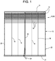
- FIG. 1 illustrates a standard or conventional sieve construction.
- the sieve 10 comprises a generally rectangular frame 12 and a plurality of overlapping banks of slats 14 .
- the slats 14 define openings 15 through which the grain falls (i.e., by gravity).
- each bank of slats 14 includes two or more slats separated by one or more dividers 16 , and each bank is mounted end-to-end on a solid metal wire 18 which is rotatably mounted between the side channels 20 of the frame 12 .
- a typical sieve is provided as being a single rectangular frame having eight or more overlapping banks of slats. In some cases, a single slat is used with no divider.
- the frame also includes one or more elongated dividers 16 extending parallel to the side channels 20 connected to ends 21 of the frame 12 and both the side channels 20 and dividers 16 include a plurality of longitudinally spaced apertures 22 , which rotatably support the solid metal wires 18 .
- a sieve 10 is assembled by sliding the wires 18 through the respective apertures 22 in each divider 16 , so that the dividers 16 are “strung” on the wires 18 before the ends of the wires 18 are inserted into straight cut, round apertures provided in the side channels 20 .
- FIG. 3 illustrates the end of the solid wires 18 being received in the apertures 22 in one of the side channels 20 of the frame 12 .
- a standard sieve also includes a handle 24 which is connected to an elongated adjustment bar 26 which extends perpendicularly to the solid metal wires 18 and includes a plurality of longitudinally spaced recesses or apertures for engaging a crank on each wire 18 , thereby controlling the angular disposition of the slats 14 and the size of the openings between the banks of slats.
- the slats 14 effectively become louvers and can be adjusted, using the handle 24 , to any position between fully open and fully closed.
- the sieve 10 is mechanically supported for reciprocal shifting movement or agitation (i.e., shaking) to cause the grain to separate from the chaff and fall downwardly through the openings 16 between the banks of slats.
- Sieves (and chaffers) in combines are subject to wear in the components, especially in the cross wires 18 that support the louvers.
- the wires 18 wear in the holes 22 in the side channels 20 and dividers 16 , and/or the holes 22 in the side channels 20 and dividers 16 wear and become elongated.
- the holes 22 need to have enough clearance to slide the wires 18 and side channel members 20 of the frame 12 together.
- springs have been used to put pressure on the wires 18 and keep them from moving.
- the springs require that high forces be applied in order to adjust the louvers.
- adding springs to the assembly increases both the overall cost of the assembly as well as increases the labor required to assemble the sieve.
- the weight of the sieves is another key consideration. If the wires 18 are made to a larger diameter, then the overall frame 12 will be heavier. Any additional weight is detrimental to the operation of the system. Adding weight to the overall sieve assembly is detrimental for a number of reasons. For example, the additional weight means heavier structures to support them. This leads to requiring a heavier mass (i.e., more power, etc.) to agitate or shake the sieve. Furthermore, combines are already very heavy machines and the industry is always trying ways to make them weigh less. Reducing the overall weight of a combine provides for reduced ground pressure (compacting of the fields and road weight limits). Finally, increasing the weight of a sieve assembly results in it being more difficult to remove/replace the sieve.
- louvers Another characteristic of sieves is related to the precision of the louvers.
- the solid wires tend to twist due to reacting forces (i.e., torsion). This causes a variation in the louver positions.
- An object of an embodiment of the present invention is to provide a high strength sieve for use in a combine harvester.
- an embodiment of the present invention provides a high strength sieve which is lightweight and durable without having to add springs, and without requiring a high level of force to effect adjustment of the louvers.
- the high strength sieve comprises hollow tubes which support the louvers.
- Providing hollow tubes i.e., rather than solid wires) allows for larger diameter holes to be used in the frame, i.e., the holes which support the tubes. This provides for an added bearing surface, as well as provides for better tolerance ratio between the diameter of the tubes vs. the diameter of the holes in the frame which support the tubes. This reduces the relative movement of the tubes within the holes.
- the tubes are mounted in the frame through holes which are extruded.
- the extruded holes also provide for an increased bearing surface, as well as promote a tighter fit between the tubes and the frame.
- the fact that the holes are extruded also works to provide a natural lead-in for the insertion of the tubes (i.e., during assembly of the sieve).
- These overall features provide for reduced wear without having to employ springs and resulting added spring pressure.
- the use of hollow tubes results in no increase in force needed to adjust the angular position of the louvers.
- the tubes have improved sectional properties compared to solid wires, thus improving the stiffness of the louvers and reducing the amount of twisting that takes place during operation.
- FIG. 1 is a top view of a standard sieve construction
- FIG. 2 provides a close up view of one of the corners of the sieve shown in FIG. 1 ;
- FIG. 3 provides a close up view of a portion of FIG. 2 , showing a solid wire extending through a straight cut hole;
- FIGS. 4 and 5 are similar to FIGS. 2 and 3 , respectively, but illustrate a construction that is in accordance with an embodiment of the present invention.
- FIG. 6 is similar to FIGS. 3 and 5 , but illustrate a construction that is in accordance with yet another embodiment of the present invention.
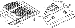
- An embodiment of the present invention provides a sieve 50 which is as shown in FIG. 1 , but instead of utilizing solid wires 18 , hollow tubes 52 are used.
- the hollow tubes 52 (much like the solid metal wires 18 of the sieve 10 shown in FIG. 1 ) support slats or louvers 14 , and the hollow tubes 52 extend from one side channel 20 of the frame 12 to another side channel 20 , and one or more dividers 16 can be also provided, connected to the ends 21 of the frame 12 .
- FIG. 4 illustrates, in more detail, the louvers 14 and the hollow tubes 52 which support the louvers 14 and which extend through apertures or holes 56 provided in the side channel members 20 and the dividers 16 .
- hollow tubes 52 as shown in FIGS. 4 and 5 (i.e., rather than solid wires 18 as shown in FIGS. 2 and 3 )
- larger diameter holes 56 can be used in the side channel members 20 and dividers 16 .
- This provides for increased bearing surfaces, as well as provides for tighter tolerances between the diameter of the hollow tubes 52 versus the diameter of the apertures 56 in the side channels members 20 and dividers 16 . This results in decreased movement (i.e., during operation) of the hollow tubes 52 within these apertures 56 .
- the apertures 56 in the side channels members 20 and dividers 16 are extruded as opposed to being straight cut.
- the extruded holes 56 also provide for increased bearing surfaces, as well as promote better tolerances between the hollow tubes 52 and the side channel members 20 and dividers 16 .
- the fact that the holes 56 are extruded also functions to make assembly of the sieve easier by providing a natural lead-in for the insertion of the tubes 52 .
- the construction disclosed herein i.e., the use of hollow tubes 52 and extruded holes 56 provide for reduced wear without having to employ springs.
- the fact that the tubes 52 are hollow does not require an increase in force needed to move the handle 24 and adjust the angular position of the louvers 14 .
- the fact that the tubes 52 are hollow improves the stiffness of the louvers 14 , as well as reduces the amount of twisting that takes place during operation.
- the tubes 52 which support the louvers 14 are hollow provides for an increased life of the sieve 50 because of reduced wear at the mounting holes 56 . Additionally, the tubes 52 provide added stiffness to the louvers 14 due to the increased sectional properties of the hollow tubes 52 , as compared to the solid wires 18 . This improves the precision of the louvers 14 . The fact that the holes 56 through which the hollow tubes 52 extend are extruded provides a larger surface for engagement by the tubes 52 . This increases the life of the sieve 50 because of reduced wear at the mounting holes 56 .
- FIG. 6 is similar to FIGS. 3 and 5 , but illustrate a construction that is in accordance with yet another embodiment of the present invention.
- a sieve is provided which is very much like those sieves described previously, with the only difference being that extruded holes 56 are provided to support solid wires 18 (i.e., instead of hollow tubes 52 ).
- the fact that the holes 56 through which the solid wires 18 extend are extruded, rather than straight cut, provides a larger surface for engagement by the wires 18 . This increases the life of the sieve because of reduced wear at the mounting holes 56 .
Landscapes
- Life Sciences & Earth Sciences (AREA)
- Environmental Sciences (AREA)
- Combined Means For Separation Of Solids (AREA)
Abstract
Description
Claims (3)
Priority Applications (4)
| Application Number | Priority Date | Filing Date | Title |
|---|---|---|---|
| US15/980,483 US10856469B2 (en) | 2017-08-22 | 2018-05-15 | High strength sieve |
| CA3006311A CA3006311A1 (en) | 2017-08-22 | 2018-05-28 | High strength sieve |
| BR102018013611-9A BR102018013611B1 (en) | 2017-08-22 | 2018-07-03 | HIGH RESISTANCE SIEVE |
| DE102018213864.8A DE102018213864A1 (en) | 2017-08-22 | 2018-08-17 | Sieve with high strength |
Applications Claiming Priority (2)
| Application Number | Priority Date | Filing Date | Title |
|---|---|---|---|
| US201762548779P | 2017-08-22 | 2017-08-22 | |
| US15/980,483 US10856469B2 (en) | 2017-08-22 | 2018-05-15 | High strength sieve |
Publications (2)
| Publication Number | Publication Date |
|---|---|
| US20190059234A1 US20190059234A1 (en) | 2019-02-28 |
| US10856469B2 true US10856469B2 (en) | 2020-12-08 |
Family
ID=65433968
Family Applications (1)
| Application Number | Title | Priority Date | Filing Date |
|---|---|---|---|
| US15/980,483 Active 2038-11-10 US10856469B2 (en) | 2017-08-22 | 2018-05-15 | High strength sieve |
Country Status (3)
| Country | Link |
|---|---|
| US (1) | US10856469B2 (en) |
| BR (1) | BR102018013611B1 (en) |
| CA (1) | CA3006311A1 (en) |
Cited By (6)
| Publication number | Priority date | Publication date | Assignee | Title |
|---|---|---|---|---|
| US11877538B1 (en) | 2022-08-30 | 2024-01-23 | Calmer Holding Company, Llc | Threshing grains and legumes utilizing concaves with adjustable openings |
| USD1031793S1 (en) | 2022-08-30 | 2024-06-18 | Calmer Holding Company, Llc | Separating grate |
| USD1031791S1 (en) | 2022-08-30 | 2024-06-18 | Calmer Holding Company, Llc | Straight bar concave |
| USD1031792S1 (en) | 2022-08-30 | 2024-06-18 | Calmer Holding Company, Llc | Round bar concave |
| USD1032666S1 (en) | 2022-08-30 | 2024-06-25 | Calmer Holding Company, Llc | MOG limiting subassembly for combine concave |
| USD1058613S1 (en) | 2022-11-29 | 2025-01-21 | Calmer Holding Company, Llc | Limiter plates |
Families Citing this family (2)
| Publication number | Priority date | Publication date | Assignee | Title |
|---|---|---|---|---|
| BR102019020537B1 (en) * | 2019-09-30 | 2020-09-08 | Gerhard Dowich | SCALE FOR GRAIN SCREEN, ADJUSTABLE SCREEN FOR GRAIN AND SCALE ADJUSTMENT METHOD FOR GRAIN SCREEN |
| CN110670919B (en) * | 2019-10-15 | 2021-03-23 | 溆浦县龙潭天然食品有限公司 | Airing and air-drying room |
Citations (30)
| Publication number | Priority date | Publication date | Assignee | Title |
|---|---|---|---|---|
| US1448725A (en) * | 1921-12-27 | 1923-03-20 | Charles Closz Company | Sieve and method of manufacturing same |
| US2253296A (en) * | 1938-11-21 | 1941-08-19 | Hart Carter Co | Screen for threshing machines |
| US2362099A (en) * | 1942-11-12 | 1944-11-07 | Reynolds Spring Co | Sieve frame |
| US2413382A (en) * | 1940-11-25 | 1946-12-31 | Hart Carter Co | Sheet metal sieve construction for harvesters |
| US3334744A (en) * | 1965-09-22 | 1967-08-08 | Int Harvester Co | Sieve construction and the like |
| US3472377A (en) * | 1968-01-22 | 1969-10-14 | Case Co J I | Sieve for combine |
| US4259829A (en) * | 1978-02-08 | 1981-04-07 | Sperry Corporation | Combine harvesters |
| US4511466A (en) * | 1983-12-14 | 1985-04-16 | Hart-Carter Company | Chaffer slat |
| US4770190A (en) * | 1987-05-15 | 1988-09-13 | Deere & Company | Cleaning shoe screen for an agricultural combine having readily replaceable louvers |
| US5462174A (en) * | 1994-04-22 | 1995-10-31 | Hcc Inc. | Sieve apparatus for combine |
| US5489029A (en) * | 1993-06-14 | 1996-02-06 | New Holland North America, Inc. | Harvester sieve opening indicator |
| US6053812A (en) * | 1997-11-24 | 2000-04-25 | Loewen Manufacturing Co. | Sieve construction for a combine harvester |
| EP1068792A1 (en) * | 1999-07-09 | 2001-01-17 | CLAAS Selbstfahrende Erntemaschinen GmbH | Device for adjusting the width of the sieve openings of a combine harvester |
| US20020128054A1 (en) * | 2001-03-10 | 2002-09-12 | Deere & Company, A Delaware Corporation | Sieve for a harvester thresher |
| US20020183103A1 (en) * | 2001-06-05 | 2002-12-05 | Anderson Mark David | Remote adjustment mechanism for a combine harvester cleaning element |
| US20030130019A1 (en) * | 2002-01-07 | 2003-07-10 | Hcc, Inc. | Slat and sieve assembly |
| US6953397B2 (en) * | 2001-04-27 | 2005-10-11 | Cnh America Llc | Device for adjusting the width of a sieve opening on combine harvesters |
| US20070000816A1 (en) * | 2002-09-05 | 2007-01-04 | Mcrobert Ian | Spreading device and adjustable grading system incorporating same |
| US20080029443A1 (en) * | 2006-08-03 | 2008-02-07 | Hcc, Inc. | Single vane slat |
| US7566266B1 (en) * | 2008-05-13 | 2009-07-28 | Cnh America Llc | Dual action corn cob separation and improved chaffer for whole corn cobs |
| US20100113113A1 (en) * | 2008-10-31 | 2010-05-06 | Ricketts Jonathan E | Agricultural combine grain cleaning sieve with adjustable spacing system |
| US20130210505A1 (en) * | 2011-11-09 | 2013-08-15 | Lutz Bischoff | Sieve for a combine harvester cleaning device |
| US20150087364A1 (en) * | 2013-09-20 | 2015-03-26 | Deere & Company | Frame for a reciprocating sieve |
| US20150087366A1 (en) * | 2013-09-20 | 2015-03-26 | Deere & Company | Lightweight hybrid material reciprocating sieve |
| US20160286728A1 (en) * | 2015-03-31 | 2016-10-06 | Cnh Industrial America Llc | Combine Harvester Grain Cleaners |
| US20160345501A1 (en) * | 2014-05-28 | 2016-12-01 | Cnh Industrial America Llc | Combine Harvester Cleaning System Drive Assembly |
| US9901033B1 (en) * | 2016-10-14 | 2018-02-27 | Deere & Company | Harvester louver wire retention system |
| US20180288940A1 (en) * | 2017-04-06 | 2018-10-11 | Deere And Company | Harvester louver rotation |
| US20190082597A1 (en) * | 2017-09-18 | 2019-03-21 | Hcc, Inc. | Louver position sensing system for a sieve and chaffer of a combine harvester |
| US20200100432A1 (en) * | 2018-10-02 | 2020-04-02 | Deere & Company | Independent air controlled sieve |
-
2018
- 2018-05-15 US US15/980,483 patent/US10856469B2/en active Active
- 2018-05-28 CA CA3006311A patent/CA3006311A1/en active Pending
- 2018-07-03 BR BR102018013611-9A patent/BR102018013611B1/en active IP Right Grant
Patent Citations (35)
| Publication number | Priority date | Publication date | Assignee | Title |
|---|---|---|---|---|
| US1448725A (en) * | 1921-12-27 | 1923-03-20 | Charles Closz Company | Sieve and method of manufacturing same |
| US2253296A (en) * | 1938-11-21 | 1941-08-19 | Hart Carter Co | Screen for threshing machines |
| US2413382A (en) * | 1940-11-25 | 1946-12-31 | Hart Carter Co | Sheet metal sieve construction for harvesters |
| US2362099A (en) * | 1942-11-12 | 1944-11-07 | Reynolds Spring Co | Sieve frame |
| US3334744A (en) * | 1965-09-22 | 1967-08-08 | Int Harvester Co | Sieve construction and the like |
| US3472377A (en) * | 1968-01-22 | 1969-10-14 | Case Co J I | Sieve for combine |
| US4259829A (en) * | 1978-02-08 | 1981-04-07 | Sperry Corporation | Combine harvesters |
| US4511466A (en) * | 1983-12-14 | 1985-04-16 | Hart-Carter Company | Chaffer slat |
| US4770190A (en) * | 1987-05-15 | 1988-09-13 | Deere & Company | Cleaning shoe screen for an agricultural combine having readily replaceable louvers |
| US5489029A (en) * | 1993-06-14 | 1996-02-06 | New Holland North America, Inc. | Harvester sieve opening indicator |
| US5462174A (en) * | 1994-04-22 | 1995-10-31 | Hcc Inc. | Sieve apparatus for combine |
| US6053812A (en) * | 1997-11-24 | 2000-04-25 | Loewen Manufacturing Co. | Sieve construction for a combine harvester |
| EP1068792A1 (en) * | 1999-07-09 | 2001-01-17 | CLAAS Selbstfahrende Erntemaschinen GmbH | Device for adjusting the width of the sieve openings of a combine harvester |
| US20020128054A1 (en) * | 2001-03-10 | 2002-09-12 | Deere & Company, A Delaware Corporation | Sieve for a harvester thresher |
| US7029392B2 (en) * | 2001-04-27 | 2006-04-18 | Cnh America Llc | Device for adjusting the width of a sieve mesh on combine harvesters |
| US6953397B2 (en) * | 2001-04-27 | 2005-10-11 | Cnh America Llc | Device for adjusting the width of a sieve opening on combine harvesters |
| US20020183103A1 (en) * | 2001-06-05 | 2002-12-05 | Anderson Mark David | Remote adjustment mechanism for a combine harvester cleaning element |
| US6890253B2 (en) * | 2002-01-07 | 2005-05-10 | Hcc, Inc. | Slat and sieve assembly |
| US20030130019A1 (en) * | 2002-01-07 | 2003-07-10 | Hcc, Inc. | Slat and sieve assembly |
| US20070000816A1 (en) * | 2002-09-05 | 2007-01-04 | Mcrobert Ian | Spreading device and adjustable grading system incorporating same |
| US7448498B2 (en) * | 2002-09-05 | 2008-11-11 | Mcrobert Ian | Spreading device and adjustable grading system incorporating same |
| US20080029443A1 (en) * | 2006-08-03 | 2008-02-07 | Hcc, Inc. | Single vane slat |
| US7909171B2 (en) * | 2006-08-03 | 2011-03-22 | Hcc, Inc. | Single vane slat |
| US7566266B1 (en) * | 2008-05-13 | 2009-07-28 | Cnh America Llc | Dual action corn cob separation and improved chaffer for whole corn cobs |
| US20100113113A1 (en) * | 2008-10-31 | 2010-05-06 | Ricketts Jonathan E | Agricultural combine grain cleaning sieve with adjustable spacing system |
| US7997967B2 (en) * | 2008-10-31 | 2011-08-16 | Cnh America Llc | Agricultural combine grain cleaning sieve with adjustable spacing system |
| US20130210505A1 (en) * | 2011-11-09 | 2013-08-15 | Lutz Bischoff | Sieve for a combine harvester cleaning device |
| US20150087364A1 (en) * | 2013-09-20 | 2015-03-26 | Deere & Company | Frame for a reciprocating sieve |
| US20150087366A1 (en) * | 2013-09-20 | 2015-03-26 | Deere & Company | Lightweight hybrid material reciprocating sieve |
| US20160345501A1 (en) * | 2014-05-28 | 2016-12-01 | Cnh Industrial America Llc | Combine Harvester Cleaning System Drive Assembly |
| US20160286728A1 (en) * | 2015-03-31 | 2016-10-06 | Cnh Industrial America Llc | Combine Harvester Grain Cleaners |
| US9901033B1 (en) * | 2016-10-14 | 2018-02-27 | Deere & Company | Harvester louver wire retention system |
| US20180288940A1 (en) * | 2017-04-06 | 2018-10-11 | Deere And Company | Harvester louver rotation |
| US20190082597A1 (en) * | 2017-09-18 | 2019-03-21 | Hcc, Inc. | Louver position sensing system for a sieve and chaffer of a combine harvester |
| US20200100432A1 (en) * | 2018-10-02 | 2020-04-02 | Deere & Company | Independent air controlled sieve |
Cited By (9)
| Publication number | Priority date | Publication date | Assignee | Title |
|---|---|---|---|---|
| US11877538B1 (en) | 2022-08-30 | 2024-01-23 | Calmer Holding Company, Llc | Threshing grains and legumes utilizing concaves with adjustable openings |
| USD1031793S1 (en) | 2022-08-30 | 2024-06-18 | Calmer Holding Company, Llc | Separating grate |
| USD1031791S1 (en) | 2022-08-30 | 2024-06-18 | Calmer Holding Company, Llc | Straight bar concave |
| USD1031792S1 (en) | 2022-08-30 | 2024-06-18 | Calmer Holding Company, Llc | Round bar concave |
| USD1032666S1 (en) | 2022-08-30 | 2024-06-25 | Calmer Holding Company, Llc | MOG limiting subassembly for combine concave |
| US12102041B2 (en) | 2022-08-30 | 2024-10-01 | Calmer Holding Company, Llc | Methods and systems for threshing/separating grains and legumes utilizing concaves |
| US12219901B2 (en) | 2022-08-30 | 2025-02-11 | Calmer Holding Company, Llc | Combine with threshing chamber defined by distinct sequences of concaves |
| US12349632B2 (en) | 2022-08-30 | 2025-07-08 | Calmer Holding Company, Llc | Threshing and separation method to separate grains from material other than grain via threshing and separating apparatuses |
| USD1058613S1 (en) | 2022-11-29 | 2025-01-21 | Calmer Holding Company, Llc | Limiter plates |
Also Published As
| Publication number | Publication date |
|---|---|
| CA3006311A1 (en) | 2019-02-22 |
| BR102018013611B1 (en) | 2023-01-10 |
| BR102018013611A2 (en) | 2019-06-11 |
| US20190059234A1 (en) | 2019-02-28 |
Similar Documents
| Publication | Publication Date | Title |
|---|---|---|
| US10856469B2 (en) | High strength sieve | |
| EP3720267B1 (en) | Concave cover plate system for a combine harvester | |
| DE602005004446T2 (en) | Grain cleaning in the combine harvester | |
| EP1712122B1 (en) | Drive system for an apparatus for conveying crop | |
| US3334744A (en) | Sieve construction and the like | |
| DE10120957C2 (en) | Device for adjusting the sieve opening width on combine harvesters | |
| US5462174A (en) | Sieve apparatus for combine | |
| US10582662B2 (en) | Manual and self adjusting deck plate for agricultural header | |
| US10654651B2 (en) | Modular eye link conveyor belt | |
| EP0334957A1 (en) | Threshing device of axial harvest combine | |
| EP2954771B1 (en) | Conveyor chain | |
| DE102018213864A1 (en) | Sieve with high strength | |
| DE19927933A1 (en) | Sieve for combine harvester has ziz-zag cross-section with repeated sections, one arm of which forms smaller angle with horizontal than second, second arm having spaced openings and first arm having extension which ends at join between arms | |
| DE3441238C2 (en) | ||
| EP3150058B1 (en) | Combine harvester | |
| EP3613276A1 (en) | Self-propelled harvester, in particular combine harvester | |
| CN205105703U (en) | Buckled plate and chaffer screen device of harvester shale shaker | |
| US33618A (en) | Improvement in screens of win nowing-mach in es | |
| GB2054335A (en) | Sieves | |
| DE102018121052A1 (en) | Component for a combine and combine with the component | |
| DE3504003C2 (en) | ||
| US721940A (en) | Grain-separating screen. | |
| US210243A (en) | Improvement in adjustable sieves | |
| US235229A (en) | Grain-separator | |
| SU1093288A1 (en) | Thrashing drum of grain harvesting combine |
Legal Events
| Date | Code | Title | Description |
|---|---|---|---|
| FEPP | Fee payment procedure |
Free format text: ENTITY STATUS SET TO UNDISCOUNTED (ORIGINAL EVENT CODE: BIG.); ENTITY STATUS OF PATENT OWNER: SMALL ENTITY |
|
| AS | Assignment |
Owner name: HCC, INC., ILLINOIS Free format text: ASSIGNMENT OF ASSIGNORS INTEREST;ASSIGNORS:MAMMEN, DAVID;AUBRY, PAUL;REEL/FRAME:045823/0667 Effective date: 20180516 |
|
| FEPP | Fee payment procedure |
Free format text: ENTITY STATUS SET TO SMALL (ORIGINAL EVENT CODE: SMAL); ENTITY STATUS OF PATENT OWNER: SMALL ENTITY |
|
| STPP | Information on status: patent application and granting procedure in general |
Free format text: DOCKETED NEW CASE - READY FOR EXAMINATION |
|
| STPP | Information on status: patent application and granting procedure in general |
Free format text: NON FINAL ACTION MAILED |
|
| STPP | Information on status: patent application and granting procedure in general |
Free format text: RESPONSE TO NON-FINAL OFFICE ACTION ENTERED AND FORWARDED TO EXAMINER |
|
| STCF | Information on status: patent grant |
Free format text: PATENTED CASE |
|
| AS | Assignment |
Owner name: CRYSTAL LAKE BANK & TRUST COMPANY, N.A., ILLINOIS Free format text: SECURITY INTEREST;ASSIGNORS:HCC, INC.;TRIPLE C MANUFACTURING, INC.;REEL/FRAME:063297/0607 Effective date: 20230313 |
|
| MAFP | Maintenance fee payment |
Free format text: PAYMENT OF MAINTENANCE FEE, 4TH YR, SMALL ENTITY (ORIGINAL EVENT CODE: M2551); ENTITY STATUS OF PATENT OWNER: SMALL ENTITY Year of fee payment: 4 |