EP3631890B1 - Hybride energieversorgungsschaltung, verwendung einer hybriden energieversorgungsschaltung und verfahren zur herstellung einer hybriden energieversorgungsschaltung - Google Patents
Hybride energieversorgungsschaltung, verwendung einer hybriden energieversorgungsschaltung und verfahren zur herstellung einer hybriden energieversorgungsschaltung Download PDFInfo
- Publication number
- EP3631890B1 EP3631890B1 EP18730989.3A EP18730989A EP3631890B1 EP 3631890 B1 EP3631890 B1 EP 3631890B1 EP 18730989 A EP18730989 A EP 18730989A EP 3631890 B1 EP3631890 B1 EP 3631890B1
- Authority
- EP
- European Patent Office
- Prior art keywords
- supply circuit
- power supply
- solid
- energy store
- energy storage
- Prior art date
- Legal status (The legal status is an assumption and is not a legal conclusion. Google has not performed a legal analysis and makes no representation as to the accuracy of the status listed.)
- Active
Links
Images



Classifications
-
- H—ELECTRICITY
- H02—GENERATION; CONVERSION OR DISTRIBUTION OF ELECTRIC POWER
- H02J—ELECTRIC POWER NETWORKS; CIRCUIT ARRANGEMENTS OR SYSTEMS FOR SUPPLYING OR DISTRIBUTING ELECTRIC POWER; SYSTEMS FOR STORING ELECTRIC ENERGY
- H02J7/00—Circuit arrangements for charging or discharging batteries or for supplying loads from batteries
- H02J7/34—Parallel operation in networks using both storage and other DC sources, e.g. providing buffering
-
- H—ELECTRICITY
- H01—ELECTRIC ELEMENTS
- H01G—CAPACITORS; CAPACITORS, RECTIFIERS, DETECTORS, SWITCHING DEVICES, LIGHT-SENSITIVE OR TEMPERATURE-SENSITIVE DEVICES OF THE ELECTROLYTIC TYPE
- H01G11/00—Hybrid capacitors, i.e. capacitors having different positive and negative electrodes; Electric double-layer [EDL] capacitors; Processes for the manufacture thereof or of parts thereof
- H01G11/08—Structural combinations, e.g. assembly or connection, of hybrid or EDL capacitors with other electric components, at least one hybrid or EDL capacitor being the main component
-
- H—ELECTRICITY
- H01—ELECTRIC ELEMENTS
- H01G—CAPACITORS; CAPACITORS, RECTIFIERS, DETECTORS, SWITCHING DEVICES, LIGHT-SENSITIVE OR TEMPERATURE-SENSITIVE DEVICES OF THE ELECTROLYTIC TYPE
- H01G11/00—Hybrid capacitors, i.e. capacitors having different positive and negative electrodes; Electric double-layer [EDL] capacitors; Processes for the manufacture thereof or of parts thereof
- H01G11/10—Multiple hybrid or EDL capacitors, e.g. arrays or modules
-
- H—ELECTRICITY
- H01—ELECTRIC ELEMENTS
- H01G—CAPACITORS; CAPACITORS, RECTIFIERS, DETECTORS, SWITCHING DEVICES, LIGHT-SENSITIVE OR TEMPERATURE-SENSITIVE DEVICES OF THE ELECTROLYTIC TYPE
- H01G4/00—Fixed capacitors; Processes of their manufacture
- H01G4/002—Details
- H01G4/228—Terminals
- H01G4/248—Terminals the terminals embracing or surrounding the capacitive element, e.g. caps
-
- H—ELECTRICITY
- H01—ELECTRIC ELEMENTS
- H01G—CAPACITORS; CAPACITORS, RECTIFIERS, DETECTORS, SWITCHING DEVICES, LIGHT-SENSITIVE OR TEMPERATURE-SENSITIVE DEVICES OF THE ELECTROLYTIC TYPE
- H01G4/00—Fixed capacitors; Processes of their manufacture
- H01G4/30—Stacked capacitors
-
- H—ELECTRICITY
- H01—ELECTRIC ELEMENTS
- H01G—CAPACITORS; CAPACITORS, RECTIFIERS, DETECTORS, SWITCHING DEVICES, LIGHT-SENSITIVE OR TEMPERATURE-SENSITIVE DEVICES OF THE ELECTROLYTIC TYPE
- H01G4/00—Fixed capacitors; Processes of their manufacture
- H01G4/38—Multiple capacitors, i.e. structural combinations of fixed capacitors
-
- H—ELECTRICITY
- H01—ELECTRIC ELEMENTS
- H01G—CAPACITORS; CAPACITORS, RECTIFIERS, DETECTORS, SWITCHING DEVICES, LIGHT-SENSITIVE OR TEMPERATURE-SENSITIVE DEVICES OF THE ELECTROLYTIC TYPE
- H01G4/00—Fixed capacitors; Processes of their manufacture
- H01G4/40—Structural combinations of fixed capacitors with other electric elements, the structure mainly consisting of a capacitor, e.g. RC combinations
-
- H—ELECTRICITY
- H01—ELECTRIC ELEMENTS
- H01G—CAPACITORS; CAPACITORS, RECTIFIERS, DETECTORS, SWITCHING DEVICES, LIGHT-SENSITIVE OR TEMPERATURE-SENSITIVE DEVICES OF THE ELECTROLYTIC TYPE
- H01G9/00—Electrolytic capacitors, rectifiers, detectors, switching devices, light-sensitive or temperature-sensitive devices; Processes of their manufacture
- H01G9/26—Structural combinations of electrolytic capacitors, rectifiers, detectors, switching devices, light-sensitive or temperature-sensitive devices with each other
-
- H—ELECTRICITY
- H01—ELECTRIC ELEMENTS
- H01G—CAPACITORS; CAPACITORS, RECTIFIERS, DETECTORS, SWITCHING DEVICES, LIGHT-SENSITIVE OR TEMPERATURE-SENSITIVE DEVICES OF THE ELECTROLYTIC TYPE
- H01G9/00—Electrolytic capacitors, rectifiers, detectors, switching devices, light-sensitive or temperature-sensitive devices; Processes of their manufacture
- H01G9/28—Structural combinations of electrolytic capacitors, rectifiers, detectors, switching devices with other electric components not covered by this subclass
-
- H—ELECTRICITY
- H01—ELECTRIC ELEMENTS
- H01M—PROCESSES OR MEANS, e.g. BATTERIES, FOR THE DIRECT CONVERSION OF CHEMICAL ENERGY INTO ELECTRICAL ENERGY
- H01M10/00—Secondary cells; Manufacture thereof
- H01M10/05—Accumulators with non-aqueous electrolyte
- H01M10/052—Li-accumulators
-
- H—ELECTRICITY
- H01—ELECTRIC ELEMENTS
- H01M—PROCESSES OR MEANS, e.g. BATTERIES, FOR THE DIRECT CONVERSION OF CHEMICAL ENERGY INTO ELECTRICAL ENERGY
- H01M10/00—Secondary cells; Manufacture thereof
- H01M10/05—Accumulators with non-aqueous electrolyte
- H01M10/056—Accumulators with non-aqueous electrolyte characterised by the materials used as electrolytes, e.g. mixed inorganic/organic electrolytes
- H01M10/0561—Accumulators with non-aqueous electrolyte characterised by the materials used as electrolytes, e.g. mixed inorganic/organic electrolytes the electrolyte being constituted of inorganic materials only
- H01M10/0562—Solid materials
-
- H—ELECTRICITY
- H01—ELECTRIC ELEMENTS
- H01M—PROCESSES OR MEANS, e.g. BATTERIES, FOR THE DIRECT CONVERSION OF CHEMICAL ENERGY INTO ELECTRICAL ENERGY
- H01M10/00—Secondary cells; Manufacture thereof
- H01M10/05—Accumulators with non-aqueous electrolyte
- H01M10/056—Accumulators with non-aqueous electrolyte characterised by the materials used as electrolytes, e.g. mixed inorganic/organic electrolytes
- H01M10/0564—Accumulators with non-aqueous electrolyte characterised by the materials used as electrolytes, e.g. mixed inorganic/organic electrolytes the electrolyte being constituted of organic materials only
- H01M10/0565—Polymeric materials, e.g. gel-type or solid-type
-
- H—ELECTRICITY
- H01—ELECTRIC ELEMENTS
- H01M—PROCESSES OR MEANS, e.g. BATTERIES, FOR THE DIRECT CONVERSION OF CHEMICAL ENERGY INTO ELECTRICAL ENERGY
- H01M16/00—Structural combinations of different types of electrochemical generators
-
- H—ELECTRICITY
- H02—GENERATION; CONVERSION OR DISTRIBUTION OF ELECTRIC POWER
- H02J—ELECTRIC POWER NETWORKS; CIRCUIT ARRANGEMENTS OR SYSTEMS FOR SUPPLYING OR DISTRIBUTING ELECTRIC POWER; SYSTEMS FOR STORING ELECTRIC ENERGY
- H02J7/00—Circuit arrangements for charging or discharging batteries or for supplying loads from batteries
- H02J7/34—Parallel operation in networks using both storage and other DC sources, e.g. providing buffering
- H02J7/345—Parallel operation in networks using both storage and other DC sources, e.g. providing buffering using capacitors as storage or buffering devices
-
- H—ELECTRICITY
- H02—GENERATION; CONVERSION OR DISTRIBUTION OF ELECTRIC POWER
- H02J—ELECTRIC POWER NETWORKS; CIRCUIT ARRANGEMENTS OR SYSTEMS FOR SUPPLYING OR DISTRIBUTING ELECTRIC POWER; SYSTEMS FOR STORING ELECTRIC ENERGY
- H02J7/00—Circuit arrangements for charging or discharging batteries or for supplying loads from batteries
- H02J7/50—Circuit arrangements for charging or discharging batteries or for supplying loads from batteries acting upon multiple batteries simultaneously or sequentially
-
- H—ELECTRICITY
- H02—GENERATION; CONVERSION OR DISTRIBUTION OF ELECTRIC POWER
- H02J—ELECTRIC POWER NETWORKS; CIRCUIT ARRANGEMENTS OR SYSTEMS FOR SUPPLYING OR DISTRIBUTING ELECTRIC POWER; SYSTEMS FOR STORING ELECTRIC ENERGY
- H02J7/00—Circuit arrangements for charging or discharging batteries or for supplying loads from batteries
- H02J7/60—Circuit arrangements for charging or discharging batteries or for supplying loads from batteries including safety or protection arrangements
-
- H—ELECTRICITY
- H02—GENERATION; CONVERSION OR DISTRIBUTION OF ELECTRIC POWER
- H02J—ELECTRIC POWER NETWORKS; CIRCUIT ARRANGEMENTS OR SYSTEMS FOR SUPPLYING OR DISTRIBUTING ELECTRIC POWER; SYSTEMS FOR STORING ELECTRIC ENERGY
- H02J7/00—Circuit arrangements for charging or discharging batteries or for supplying loads from batteries
- H02J7/60—Circuit arrangements for charging or discharging batteries or for supplying loads from batteries including safety or protection arrangements
- H02J7/61—Circuit arrangements for charging or discharging batteries or for supplying loads from batteries including safety or protection arrangements against overcharge
-
- H—ELECTRICITY
- H02—GENERATION; CONVERSION OR DISTRIBUTION OF ELECTRIC POWER
- H02J—ELECTRIC POWER NETWORKS; CIRCUIT ARRANGEMENTS OR SYSTEMS FOR SUPPLYING OR DISTRIBUTING ELECTRIC POWER; SYSTEMS FOR STORING ELECTRIC ENERGY
- H02J7/00—Circuit arrangements for charging or discharging batteries or for supplying loads from batteries
- H02J7/60—Circuit arrangements for charging or discharging batteries or for supplying loads from batteries including safety or protection arrangements
- H02J7/63—Circuit arrangements for charging or discharging batteries or for supplying loads from batteries including safety or protection arrangements against overdischarge
-
- H—ELECTRICITY
- H02—GENERATION; CONVERSION OR DISTRIBUTION OF ELECTRIC POWER
- H02J—ELECTRIC POWER NETWORKS; CIRCUIT ARRANGEMENTS OR SYSTEMS FOR SUPPLYING OR DISTRIBUTING ELECTRIC POWER; SYSTEMS FOR STORING ELECTRIC ENERGY
- H02J7/00—Circuit arrangements for charging or discharging batteries or for supplying loads from batteries
- H02J7/70—Circuit arrangements for charging or discharging batteries or for supplying loads from batteries characterised by the mechanical construction
-
- H—ELECTRICITY
- H02—GENERATION; CONVERSION OR DISTRIBUTION OF ELECTRIC POWER
- H02J—ELECTRIC POWER NETWORKS; CIRCUIT ARRANGEMENTS OR SYSTEMS FOR SUPPLYING OR DISTRIBUTING ELECTRIC POWER; SYSTEMS FOR STORING ELECTRIC ENERGY
- H02J7/00—Circuit arrangements for charging or discharging batteries or for supplying loads from batteries
- H02J7/90—Regulation of charging or discharging current or voltage
-
- H—ELECTRICITY
- H01—ELECTRIC ELEMENTS
- H01M—PROCESSES OR MEANS, e.g. BATTERIES, FOR THE DIRECT CONVERSION OF CHEMICAL ENERGY INTO ELECTRICAL ENERGY
- H01M10/00—Secondary cells; Manufacture thereof
- H01M10/05—Accumulators with non-aqueous electrolyte
- H01M10/058—Construction or manufacture
- H01M10/0585—Construction or manufacture of accumulators having only flat construction elements, i.e. flat positive electrodes, flat negative electrodes and flat separators
-
- H—ELECTRICITY
- H01—ELECTRIC ELEMENTS
- H01M—PROCESSES OR MEANS, e.g. BATTERIES, FOR THE DIRECT CONVERSION OF CHEMICAL ENERGY INTO ELECTRICAL ENERGY
- H01M10/00—Secondary cells; Manufacture thereof
- H01M10/42—Methods or arrangements for servicing or maintenance of secondary cells or secondary half-cells
- H01M10/44—Methods for charging or discharging
-
- H—ELECTRICITY
- H01—ELECTRIC ELEMENTS
- H01M—PROCESSES OR MEANS, e.g. BATTERIES, FOR THE DIRECT CONVERSION OF CHEMICAL ENERGY INTO ELECTRICAL ENERGY
- H01M2300/00—Electrolytes
- H01M2300/0017—Non-aqueous electrolytes
- H01M2300/0065—Solid electrolytes
- H01M2300/0068—Solid electrolytes inorganic
-
- H—ELECTRICITY
- H01—ELECTRIC ELEMENTS
- H01M—PROCESSES OR MEANS, e.g. BATTERIES, FOR THE DIRECT CONVERSION OF CHEMICAL ENERGY INTO ELECTRICAL ENERGY
- H01M4/00—Electrodes
- H01M4/02—Electrodes composed of, or comprising, active material
- H01M4/36—Selection of substances as active materials, active masses, active liquids
- H01M4/58—Selection of substances as active materials, active masses, active liquids of inorganic compounds other than oxides or hydroxides, e.g. sulfides, selenides, tellurides, halogenides or LiCoFy; of polyanionic structures, e.g. phosphates, silicates or borates
- H01M4/5825—Oxygenated metallic salts or polyanionic structures, e.g. borates, phosphates, silicates, olivines
-
- H—ELECTRICITY
- H02—GENERATION; CONVERSION OR DISTRIBUTION OF ELECTRIC POWER
- H02J—ELECTRIC POWER NETWORKS; CIRCUIT ARRANGEMENTS OR SYSTEMS FOR SUPPLYING OR DISTRIBUTING ELECTRIC POWER; SYSTEMS FOR STORING ELECTRIC ENERGY
- H02J2207/00—Details of circuit arrangements for charging or discharging batteries or supplying loads from batteries
- H02J2207/50—Charging of capacitors, supercapacitors, ultra-capacitors or double layer capacitors
-
- Y—GENERAL TAGGING OF NEW TECHNOLOGICAL DEVELOPMENTS; GENERAL TAGGING OF CROSS-SECTIONAL TECHNOLOGIES SPANNING OVER SEVERAL SECTIONS OF THE IPC; TECHNICAL SUBJECTS COVERED BY FORMER USPC CROSS-REFERENCE ART COLLECTIONS [XRACs] AND DIGESTS
- Y02—TECHNOLOGIES OR APPLICATIONS FOR MITIGATION OR ADAPTATION AGAINST CLIMATE CHANGE
- Y02E—REDUCTION OF GREENHOUSE GAS [GHG] EMISSIONS, RELATED TO ENERGY GENERATION, TRANSMISSION OR DISTRIBUTION
- Y02E60/00—Enabling technologies; Technologies with a potential or indirect contribution to GHG emissions mitigation
- Y02E60/10—Energy storage using batteries
Definitions
- the invention relates to a hybrid power supply for electrical circuits that have specific requirements for an energy source.
- Modern electrical components should have the smallest possible dimensions and provide more and more electrical functions. To do this, they require energy sources that provide a supply voltage that is as stable as possible, can withstand a high number of cycles without degradation and have short response times to charging or discharging pulses.
- Batteries or accumulators are well suited for applications with continuous load current operation. Batteries are problematic in applications with pulsed additional load and/or irregular charging cycles.
- IOT Internet of Things
- batteries are designed so that the continuous load is well covered can, energy supply becomes problematic with additional load. If a battery is designed so that it can always serve additional loads, it will be oversized for most of the time.
- the publication EP 1273058 B1 discloses a power supply circuit with battery layers successively deposited on a substrate. A capacitor can be arranged on the battery layers.
- the DE 102013112578 A1 discloses a power supply circuit in which an accumulator is connected to a capacitor. From the US 2011/064977 A1 An accumulator is known in which Zener diodes are used to stabilize the voltage. From the US 2013/266827 A1 and DE 202012010789 U1 Drive systems with solid-state batteries are known.
- the publication JP 2003 132941 A discloses a solid electrolyte battery with an integrated capacitor, in which a solid electrolyte layer is applied to a capacitor by sputtering.
- the publication US 2014/181540 A1 discloses a hybrid battery pack comprising a Li-polymer battery connected in parallel with a supercapacitor.
- the hybrid power supply circuit includes a first energy storage and a second energy storage.
- the first and second energy storage devices are combined in a module and electrically connected.
- the first energy storage device is a solid-state battery.
- the combination of two different energy storage devices allows electrical devices to be operated with a continuous load and at the same time to provide an energy supply with sufficient power for short power peaks, e.g. pulsed additional loads.
- Solid-state batteries can be manufactured in almost any shape. Solid-state batteries have a high energy density and can therefore be used with small ones Dimensions are provided. Such accumulators are relatively insensitive to damage and the loss of an electrolyte because no liquid electrolyte is present. Solid-state batteries can also consist of materials that are compatible with manufacturing processes for other circuit components.
- the hybrid energy supply circuit described here represents an improvement, especially in comparison with conventional hybrid systems consisting of batteries or conventional accumulators on the one hand and capacitors on the other.
- the second energy storage is a capacitor.
- the second energy storage can be selected from a ceramic capacitor and a multi-layer ceramic capacitor.
- Such capacitors also have a high energy density and allow the ongoing trend towards miniaturization of electrical devices to be continued.
- Solid-state accumulators represent a voltage-stable energy source. Capacitors are characterized by high cycle stability and rapid response to charging and discharging pulses.
- the hybrid energy supply circuit described is maintenance-neutral, meaning that it does not require any more maintenance than conventional hybrid energy supply circuits. Rather, it enables a smaller design and, due to the absence of a liquid electrolyte, the service life and reliability are improved.
- ASIC application-specific integrated circuit
- Such ASICs can be optimized for specific parameters, e.g. energy efficiency, for a specific application.
- Such a circuit makes it possible to protect the accumulator from deep discharge or overload when charging.
- the circuit in the ASIC chip is electrically coupled to the first energy storage and the second energy storage.
- the first energy storage and the second energy storage are also electrically coupled to one another. It is conceivable that the two energy storage devices are connected in series or - preferably - in parallel.
- Both energy storage devices can be connected to a first connection and a second connection via which the hybrid energy supply circuit can be charged and via which the energy supply circuit can deliver electrical energy to a circuit environment.
- the first energy storage and the second energy storage are produced together monolithically as a multi-layer system in a multi-layer process.
- a multi-layer system has a large number of layers made of different materials arranged one above the other. Dielectric layers and electrically conductive layers can alternate.
- a capacitive element for example, can have a large number of electrode layers in metallization levels with dielectric layers arranged between them. Adjacent electrode layers arranged one above the other are alternately connected to one of two connection electrodes.
- a solid-state battery can also have layers of structured electrode layers arranged one above the other and electrolyte layers arranged between them.
- HTCC High temperature cofire ceramics
- LTCC Low temperature cofire ceramics
- multilayer ceramic substrates can be manufactured that include both capacitors and solid-state batteries. This allows extreme energy and power densities to be achieved.
- the solid-state accumulator is suitable for reflow. This means that the solid-state battery is so thermally stable that it can withstand the temperatures when going through a reflow soldering process without being damaged.
- the power supply circuit further comprises a varistor and/or a diode, e.g. a Zener diode, for limiting a voltage to a minimum value (e.g. when discharging) or a maximum value (e.g. when charging).
- a varistor and/or a diode e.g. a Zener diode
- a varistor is a circuit element with an electrical resistance that depends on the applied voltage. The electrical resistance decreases as the applied voltage increases.
- the varistor is preferably connected in parallel to the first energy storage and/or in parallel to the second energy storage.
- Zener diode If a Zener diode is used, this also helps to limit the voltage and/or protect against overload.
- first energy storage and the second energy storage are connected directly to one another.
- the first and second energy storage devices can be arranged one above the other or can be arranged next to one another.
- the solid-state battery is made of materials that are compatible with a co-firing process, e.g. for producing an HTCC or LTCC multilayer component.
- the solid electrolyte of the solid-state battery can be selected from the following compounds: Li 1+x Al x Ti 2-x (PO 4 ) 3 (0 ⁇ x ⁇ 0.6) La 0.5 Li 0.5 TiO 3 , Li 14 Zn(GeO 4 ) 4 , Li 7 La 3 Zr 2 O 12 , Li 1.3 Al 0.3 Ti 1.7 (PO 4 ) 3 , Li 1.5 Al 0.5 Ge 1.5 (PO 4 ) 3 , Li 3.25 Ge 0.25 P 0.75 S 4 , Li 3 HP 4 , Li 2 SP 2 S 5 , Li 2 OV 2 O 5 -SiO 2 , Li3PO4 , Li 3.5 Si 0.5 P 0.5 O 4 , Li 2.9 PO 3.3 N 0.46 ,
- the material of the electrodes of the solid-state battery can be selected from the following materials: LiVOPO 4 and Li 3 V 2 (PO4) 3
- the power supply circuit is suitable for being used in an electrical component that additionally has an HF transmitter, an HF receiver and/or an HF transceiver.
- Appropriate antennas and front-end circuits may also be present.
- a method of manufacturing a hybrid power supply circuit includes combining a capacitor with a solid-state battery in a compact module.
- a layer system for the capacitor and a layer system for the solid-state battery are brought together in a multi-layer process to form a monolithic module.
- the capacitor and the solid-state battery are processed together using processing steps manufactured for multi-layer processes, so that a compact, monolithically integrated module is obtained.
- hybrid energy supply system or the hybrid energy supply system of such a device can be charged using different energy sources.
- These include photovoltaic charging systems and piezoelectric generators.
- Such and other charging systems differ from a charger that is powered by a power grid, for example, in that they have very variable charging power.
- the hybrid energy supply system is easily able to absorb the associated irregular charging current without thermal or other problems.
- the solid-state accumulator can consist of materials that are insensitive to a deep discharge, possibly up to 0 V. Otherwise, an ASIC can prevent deep discharge or overload when charging.
- the hybrid power supply system may include additional circuit elements, e.g. additional passive circuit elements or additional active circuit elements.
- a guard function can be implemented in an ASIC chip to optimize the charging of the battery, especially with irregular charging pulses.
- FIGS. 1 to 6 and 8 to 10 show examples to illustrate various aspects of the invention. These are only embodiments of the invention if the energy storage devices are monolithically manufactured as a multi-layer system in a co-fire multi-layer process and monolithically integrated in a ceramic multi-layer substrate and the further features of the independent claims are met.
- Figure 1 shows an equivalent circuit diagram of a hybrid energy supply circuit HEVS, which has a first energy storage ES1 and a second energy storage ES2.
- the first energy storage ES1 and the second energy storage ES2 are connected in parallel to one another. Both energy storage devices are connected to a first connection A1 and a second A2.
- the hybrid power supply circuit can deliver electrical energy to an external circuit environment or receive electrical energy from an external circuit environment via the two connections A1, A2.
- the first energy storage ES1 is a solid-state battery.
- the second energy storage ES2 is preferably a capacitor.
- Both the first energy storage ES1 and the second energy storage ES2 can preferably have as a multi-layer component with electrode layers as structured elements in metallization layers and dielectric layers or electrolyte layers arranged between them in the case of the accumulator.
- Figure 2 shows a possible side-by-side arrangement of the first energy storage ES1 relative to the second energy storage ES2. It is preferred to arrange the energy storage devices relative to one another in such a way that the overall structure is as small as possible.
- Both the first energy storage and the second energy storage are preferably multi-layer components with a flat structure, in which the width and depth can each be significantly higher than the height.
- Figure 3 shows a possible arrangement of the two energy storage devices one above the other.
- the two energy storage devices are designed as flat components, it is advantageous to arrange both components one above the other.
- both the first energy storage ES1 and the second energy storage ES2 can be manufactured as SMD-capable individual components. They can then be arranged one above the other and soldered together and thereby electrically connected and mechanically firmly connected.
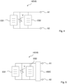
- Figure 4 shows a possible equivalent circuit diagram of a hybrid energy supply circuit HEVS, in which a varistor V is connected in parallel to the first energy storage ES1 and in parallel to the second energy storage ES2.
- the varistor provides protection against overcharging when the power supply circuit is charged via connections A1, A2.
- the second energy storage device ES2 can easily absorb short voltage peaks or charge peaks.
- FIG. 5 shows the use of an ASIC (application-specific integrated circuit).
- the ASIC is connected to the energy storage and the two connections A1, A2 and can be used to control the charging process or the discharging process.
- the ASIC can be embedded in an ASIC chip and designed to have the lowest possible energy consumption, i.e. to work as energy-efficiently as possible.
- Figure 6 shows a cross section through a component in which the first energy storage ES1 and the second energy storage ES2 are embedded in a carrier substrate TS.
- An ASIC chip is arranged on the top of the carrier substrate.
- Further circuit elements SE can be embedded in the carrier substrate.
- the various components can be connected to one another via metallized signal lines in the carrier substrate or on the top of the carrier substrate and through plated-through holes through the carrier substrate.
- circuit elements it is also possible for further circuit elements to be arranged and connected on the top of the carrier substrate TS.
- Figure 7 shows a cross section of an embodiment according to the invention, in which the components of the first energy storage ES1 and the components of the second energy storage ES2 are monolithically integrated in a carrier substrate TS.
- the carrier substrate is a ceramic multi-layer substrate, for example an LTCC substrate or an HTCC substrate.
Landscapes
- Engineering & Computer Science (AREA)
- Power Engineering (AREA)
- Chemical & Material Sciences (AREA)
- Manufacturing & Machinery (AREA)
- Microelectronics & Electronic Packaging (AREA)
- Chemical Kinetics & Catalysis (AREA)
- Electrochemistry (AREA)
- General Chemical & Material Sciences (AREA)
- General Physics & Mathematics (AREA)
- Inorganic Chemistry (AREA)
- Condensed Matter Physics & Semiconductors (AREA)
- Physics & Mathematics (AREA)
- Dispersion Chemistry (AREA)
- Charge And Discharge Circuits For Batteries Or The Like (AREA)
- Secondary Cells (AREA)
- Battery Mounting, Suspending (AREA)
- Fixed Capacitors And Capacitor Manufacturing Machines (AREA)
Description
- Die Erfindung betrifft eine hybride Energieversorgung für elektrische Schaltungen, die spezifische Anforderungen an eine Energiequelle haben.
- Moderne elektrische Bauelemente sollen möglichst kleine Abmessungen haben und immer mehr elektrische Funktionen zur Verfügung stellen. Dazu benötigen sie Energiequellen, die eine möglichst spannungsstabile Versorgungsspannung zur Verfügung stellen, eine hohe Anzahl an Zyklen ohne Degradation durchhalten und kurze Reaktionszeiten auf Lade- bzw. Entladepulse aufweisen.
- Es gibt die Möglichkeit, elektrische Geräte durch Batterien oder Akkumulatoren mit elektrischer Energie zu versorgen. Batterien oder Akkumulatoren eignen sich gut für Anwendungen mit kontinuierlichem Laststrombetrieb. Problematisch sind Batterien bei Anwendungen mit gepulster Zusatzlast und/oder unregelmäßigem Ladezyklus.
- Beim sogenannten Internet of Things (IOT) sollen eine Vielzahl unterschiedlicher elektrischer Geräte vorzugsweise über Funkverbindungen miteinander kommunizieren. Eine kontinuierliche Kommunikation ist dabei nicht notwendig. Speziell in Geräten, in denen Sensoren kontinuierlich laufen und eine Kommunikation mit einer externen Umgebung in regelmäßigen oder unregelmäßigen Abständen stattfinden soll, ist die Verwendung von Batterien problematisch. Werden die Batterien so ausgelegt, dass die kontinuierliche Last gut abgedeckt werden kann, wird eine Energieversorgung bei zusätzlicher Last problematisch. Wird eine Batterie so ausgelegt, dass sie auch zusätzliche Lasten stets bedienen kann, ist sie für die meiste Zeit überdimensioniert.
- Es besteht deshalb der Wunsch nach einer Energieversorgungsschaltung, die die oben genannten Spezifikationen erfüllt.
- Die Druckschrift
EP 1273058 B1 offenbart eine Energieversorgungsschaltung mit Batterieschichten, die nacheinander auf einem Substrat abgeschieden werden. Auf den Batterieschichten kann ein Kondensator angeordnet werden. - Die
DE 102013112578 A1 offenbart eine Energieversorgungsschaltung, bei dem ein Akkumulator mit einem Kondensator verschaltet ist. Aus derUS 2011/064977 A1 ist ein Akkumulator bekannt, bei dem Zenerdioden zur Spannungsstabilisierung eingesetzt werden. Aus derUS 2013/266827 A1 undDE 202012010789 U1 sind Antriebssysteme mit Festkörperakkumulatoren bekannt. - Die Druckschrift
JP 2003 132941 A - Die Druckschrift
US 2014/181540 A1 offenbart ein hybrides Batteriepaket umfassend eine Li-Polymer-Batterie, die mit einem Superkondensator parallel verschaltet ist. - Co-fire-Verfahren (in wortwörtlicher deutscher Übersetzung "Ko-Feuer"-Verfahren) sind aus dem Fachwissen bekannt, wie beispielsweise durch die Wikipedia-Artikel zu Co-fired ceramic (2017, 2. März,
- https://en.wikipedia.org/w/index.php?title=Co-fired ceramic&oldid=76821978) und zu Low-Temperature Cofired Ceramics (2016, 7. Oktober,
- https://de.wikipedia.org/w/index.php?title=Low Temperature Co fired Ceramics&oldid=158557554) hervorgeht.
- Es ist eine zu lösende Aufgabe, eine hybride Energieversorgungsschaltung mit verbesserten Eigenschaften anzugeben.
- Der Schutzumfang wird durch die unabhängigen Ansprüche bestimmt. Die abhängigen Ansprüche geben vorteilhafte Ausgestaltungen der Erfindung an.
- Die hybride Energieversorgungsschaltung umfasst einen ersten Energiespeicher und einen zweiten Energiespeicher. Der erste und der zweite Energiespeicher sind in einem Modul zusammengefasst und elektrisch verschaltet. Der erste Energiespeicher ist ein Festkörperakkumulator.
- Die Kombination zweier verschiedener Energiespeicher, von denen ein Energiespeicher ein Festkörperakkumulator ist, erlaubt es, elektrische Geräte mit einer kontinuierlichen Dauerlast zu betreiben und gleichzeitig eine Energieversorgung mit einer ausreichenden Leistung für kurze Leistungsspitzen, z.B. gepulste Zusatzlasten, zur Verfügung zu stellen.
- Die Verwendung eines Festkörperakkumulators als ersten Energiespeicher, der im Wesentlichen für eine kontinuierliche Dauerlast zuständig sein kann, bringt eine Menge an Vorteile mit sich: Festkörperakkumulatoren können in beinahe beliebiger Form hergestellt werden. Festkörperakkumulatoren weisen eine hohe Energiedichte auf und können deshalb mit kleinen Abmessungen bereitgestellt werden. Solche Akkumulatoren sind relativ unempfindlich gegenüber Beschädigungen und dem Verlust eines Elektrolyten, da kein flüssiger Elektrolyt vorhanden ist. Festkörperakkumulatoren können dabei zusätzlich aus Materialien bestehen, die mit Herstellungsprozessen für übrige Schaltungskomponenten kompatibel sind.
- Speziell im Vergleich mit konventionellen Hybridsystemen aus Batterien oder konventionellen Akkumulatoren einerseits und Kondensatoren andererseits stellt die hier beschriebene hybride Energieversorgungsschaltung eine Verbesserung dar.
- Der zweite Energiespeicher ist ein Kondensator. Der zweite Energiespeicher kann ausgewählt sein aus einem Keramikkondensator und einem Mehrlagenkeramikkondensator.
- Solche Kondensatoren weisen ebenfalls eine hohe Energiedichte auf und erlauben das Fortführen des anhaltenden Trends zur Miniaturisierung elektrischer Geräte.
- Festkörperakkumulatoren stellen eine spannungsstabile Energiequelle dar. Kondensatoren zeichnen sich durch eine hohe Zyklenfestigkeit und schnelle Reaktion auf Lade- und Entladepulse aus.
- Die beschriebene hybride Energieversorgungsschaltung ist dabei wartungsneutral, das heißt sie weist nicht mehr Wartung als konventionelle hybride Energieversorgungsschaltungen auf. Vielmehr ermöglicht sie eine kleinere Bauform und aufgrund des Verzichts auf einen flüssigen Elektrolyten sind die Lebensdauer und die Zuverlässigkeit verbessert.
- Es ist möglich, dass die Energieversorgungsschaltung zusätzlich einen ASIC-Chip (ASIC = application-specific integrated circuit = anwendungsspezifische integrierte Schaltung) zum Steuern oder zum Regeln eines Lade- oder Entladeprozesses aufweist.
- Solche ASICs können für eine bestimmte Anwendung auf bestimmte Parameter, z.B. Energieeffizienz optimiert sein. Eine solche Schaltung ermöglicht es, den Akkumulator vor einer Tiefenentladung oder vor einer Überbeanspruchung beim Laden zu schützen.
- Die Schaltung im ASIC-Chip ist dabei mit dem ersten Energiespeicher und dem zweiten Energiespeicher elektrisch gekoppelt.
- Der erste Energiespeicher und der zweite Energiespeicher sind ebenfalls elektrisch miteinander gekoppelt. Es ist denkbar, dass die beiden Energiespeicher in Serie oder - vorzugsweise - parallel verschaltet sind.
- Beide Energiespeicher können dabei mit einem ersten Anschluss und einem zweiten Anschluss verschaltet sein, über die die hybride Energieversorgungsschaltung geladen werden kann und über die die Energieversorgungsschaltung elektrische Energie an eine Schaltungsumgebung abgeben kann.
- Nicht erfindungsgemäß ist es, dass der erste und der zweite Energiespeicher als ein erstes und zweites SMD-Bauelement (SMD = surface mounted device = oberflächenmontiertes Schaltungselement) ausgeführt sind. Bei einer derartigen Ausbildung können das erste und das zweite SMD-Bauelement übereinander oder nebeneinander angeordnet und miteinander verschaltet sein.
- Erfindungsgemäß sind der erste Energiespeicher und der zweite Energiespeicher zusammen als ein Mehrlagensystem in einem Vielschichtprozess monolithisch hergestellt.
- Ein Mehrlagensystem hat dabei eine Vielzahl übereinander angeordneter Lagen aus unterschiedlichen Materialien. Dabei können sich dielektrische Schichten und elektrisch leitende Schichten abwechseln.
- Ein kapazitives Element beispielsweise kann eine Vielzahl an Elektrodenlagen in Metallisierungsebenen mit dazwischen angeordneten dielektrischen Schichten aufweisen. Übereinander angeordnete, benachbarte Elektrodenlagen sind dabei abwechselnd mit jeweils einer von zwei Anschlusselektroden verschaltet.
- Analog dazu kann ein Festkörperakkumulator ebenfalls übereinander angeordnete Schichtenlagen aus strukturierten Elektrodenlagen und dazwischen angeordneten Elektrolytlagen aufweisen.
- Mehrlagensysteme, z.B. HTCC-Schichtenstapel (HTCC = High temperature cofire ceramics) oder LTCC-Mehrlagensysteme (LTCC = Low temperature cofire ceramics) werden durch entsprechende bekannte und gut beherrschbare Vielschichtprozesse hergestellt.
- Es ist möglich, einen Satz aus Materialien zu finden, mit dem einerseits ein Mehrlagenkondensator und andererseits ein Festkörperakkumulator hergestellt werden kann. Dabei sind die Materialien vorzugsweise so ausgesucht, dass sie zu Verfahren zur Herstellung von solchen Mehrlagenkomponenten kompatibel sind.
- Es wurde also herausgefunden, dass Mehrlagenkeramiksubstrate hergestellt werden können die sowohl Kondensatoren als auch Festkörperakkumulatoren beinhalten. Dadurch können extreme Energie- und Leistungsdichten erhalten werden.
- Aber auch die übereinander Anordnung von SMD-Bauelementen in Form von Kondensatoren und Festkörperakkumulatoren erlauben eine extrem hohe Energie- und Leistungsdichte.
- Es ist bevorzugt, wenn der Festkörperakkumulator reflow-geeignet ist. Das heißt, der Festkörperakkumulator ist thermisch so stabil, dass er die Temperaturen beim Durchlaufen eines reflow-Löt-Prozesses aushält, ohne Schaden zu nehmen.
- Die Energieversorgungsschaltung umfasst ferner einen Varistor und/oder eine Diode, z.B. eine Zener-Diode, zum Begrenzen einer Spannung auf einen Minimalwert (z.B. beim Entladen) oder einen Maximalwert (z.B. beim Laden) umfasst.
- Ein Varistor ist dabei ein Schaltungselement mit einem elektrischen Widerstand, der von der angelegten Spannung abhängt. Der elektrische Widerstand sinkt dabei mit zunehmender angelegter Spannung.
- Der Varistor ist dabei vorzugsweise parallel zum ersten Energiespeicher und/oder parallel zum zweiten Energiespeicher geschaltet.
- Wird eine Zener-Diode verwendet, so hilft diese ebenfalls zur Spannungsbegrenzung und/oder als Schutz gegen eine Überlastung.
- Es ist entsprechend möglich, dass der erste Energiespeicher und der zweite Energiespeicher direkt miteinander verschaltet, sind.
- Der erste und der zweite Energiespeicher können übereinander angeordnet oder nebeneinander angeordnet sein.
- Der Festkörperakkumulator besteht aus Materialien, die mit einem Ko-Feuer-Prozess, z.B. zur Herstellung einer HTCC- oder LTCC-Mehrlagenkomponente, kompatibel sind.
- Der Festkörperelektrolyt des Festkörperakkumulators kann dabei aus folgenden Verbindungen ausgewählt sein:
Li1+xAlxTi2-x(PO4)3 (0≦x≦0.6)
La0.5Li0.5TiO3,
Li14Zn(GeO4)4,
Li7La3Zr2O12,
Li1.3Al0.3Ti1.7(PO4)3 ,
Li1.5Al0.5Ge1.5(PO4)3,
Li3.25Ge0.25P0.75S4 ,
Li3PS4,
Li2S-P2S5 ,
Li2O-V2O5-SiO2,
Li3PO4,
Li3.5Si0.5P0.5O4,
Li2.9PO3.3N0.46 ,
- Das Material der Elektroden des Festkörperakkumulators kann dabei aus folgenden Materialien ausgewählt sein: LiVOPO4 und Li3V2(PO4)3
- Die Energieversorgungsschaltung ist dazu geeignet, in einem elektrischen Bauelement, das zusätzlich einen HF-Sender, einen HF-Empfänger und/oder einen HF-Transceiver aufweist, verwendet zu werden.
- Entsprechende Antennen und Frontend-Schaltungen können ebenfalls vorhanden sein.
- Ein Verfahren zur Herstellung einer hybriden Energieversorgungsschaltung umfasst das Kombinieren eines Kondensators mit einem Festkörperakkumulators in einem kompakten Modul.
- In dem Verfahren wird ein Lagensystem für den Kondensator und ein Lagensystem für den Festkörperakkumulator in einem Vielschichtprozess zu einem monolithischen Modul zusammengeführt.
- Mit anderen Worten: Der Kondensator und der Festkörperakkumulator werden zusammen unter Verwendung von Prozessierungsschritten für Vielschichtprozesse hergestellt, sodass ein kompaktes monolithisch integriertes Modul erhalten wird.
- Elektrische Geräte mit einem derartigen hybriden Energieversorgungssystem bzw. das hybride Energieversorgungssystem eines solchen Geräts kann durch unterschiedliche Energiequellen geladen werden. Dazu gehören photovoltaische Ladungssysteme und piezoelektrische Generatoren. Solche und andere Ladungssysteme unterscheiden sich z.B. von einem Ladegerät, das von einem Stromnetz gespeist wird, durch eine sehr variable Ladeleistung. Das hybride Energieversorgungssystem ist dabei leicht in der Lage den zugehörigen unregelmäßigen Ladestrom ohne thermische oder anderweitige Probleme aufzunehmen.
- Der Festkörperakkumulator kann aus solchen Materialien bestehen, die unempfindlich gegenüber einer tiefen Entladung, ggf. bis 0 V, sind. Ansonsten kann eine ASIC eine Tiefenentladung oder eine Überbeanspruchung beim Aufladen verhindern.
- Das hybride Energieversorgungssystem kann zusätzliche Schaltungselemente, z.B. zusätzliche passive Schaltungselemente oder zusätzliche aktive Schaltungselemente umfassen. In einem ASIC-Chip kann eine Wächterfunktion implementiert sein, um das Laden der Batterie, insbesondere bei unregelmäßigen Ladungsimpulsen, zu optimieren.
- Wichtige Funktionsprinzipien und Details bevorzugter Ausführungsformen sind in den schematischen Figuren näher erläutert.
- Es zeigen:
- Figur 1:
- ein Ersatzschaltbild einer hybriden Energieversorgungsschaltung.
- Figur 2:
- eine mögliche Anordnung der Energiespeicher nebeneinander.
- Figur 3:
- eine mögliche Anordnung der Energiespeicher übereinander.
- Figur 4:
- die Verwendung eines Varistors.
- Figur 5:
- die Verwendung einer ASIC.
- Figur 6:
- einen Querschnitt durch ein entsprechendes Bauelement.
- Figur 7:
- einen Querschnitt durch eine erfindungsgemäße Ausführungsform eines Bauelements.
- Figur 8:
- eine perspektivische Ansicht einer Mehrlagenkomponente:
- Figur 9:
- eine mögliche Verschaltung mit einer externen Schaltung.
- Figur 10:
- eine mögliche Verschaltung mit einer Ladeschaltung.
- Die
Figuren 1 bis 6 und8 bis 10 zeigen Beispiele, um verschiedene Aspekte der Erfindung zu erläutern. Es handelt sich nur dann um Ausführungsformen der Erfindung, sofern die Energiespeicher als ein Mehrlagensystem in einem Ko-Feuer-Vielschichtprozess monolithisch hergestellt und monolithisch in einem keramischen Mehrlagensubstrat integriert sind und die weiteren Merkmale der unabhängigen Ansprüche erfüllt sind. -
Figur 1 zeigt ein Ersatzschaltbild einer hybriden Energieversorgungsschaltung HEVS, die einen ersten Energiespeicher ES1 und einen zweiten Energiespeicher ES2 aufweist. Der erste Energiespeicher ES1 und der zweite Energiespeicher ES2 sind parallel zueinander verschaltet. Beide Energiespeicher sind einem ersten Anschluss A1 und einem zweiten A2 verschaltet. Über die beiden Anschlüsse A1, A2 kann die hybride Energieversorgungsschaltung elektrische Energie an eine externe Schaltungsumgebung abgeben oder elektrische Energie von einer externen Schaltungsumgebung entgegennehmen. - Der erste Energiespeicher ES1 ist dabei ein Festkörperakkumulator. Der zweite Energiespeicher ES2 ist vorzugsweise ein Kondensator.
- Sowohl der erste Energiespeicher ES1 als auch der zweite Energiespeicher ES2 können vorzugsweise als Mehrlagenkomponente mit Elektrodenlagen als strukturierte Elemente in Metallisierungslagen und dazwischen angeordneten dielektrischen Lagen oder Elektrolytlagen im Falle des Akkumulators aufweisen.
-
Figur 2 zeigt eine mögliche Nebeneinander-Anordnung des ersten Energiespeichers ES1 relativ zum zweiten Energiespeicher ES2. Es ist bevorzugt, die Energiespeicher relativ zueinander so anzuordnen, dass ein insgesamt möglichst kleiner Aufbau erhalten wird. Sowohl der erste Energiespeicher als auch der zweite Energiespeicher sind vorzugsweise Mehrlagenkomponenten mit einem flächigen Aufbau, bei denen die Breite und die Tiefe jeweils deutlich höher als die Höhe sein können. -
Figur 3 zeigt eine mögliche Anordnung der beiden Energiespeicher übereinander. - Insbesondere wenn die beiden Energiespeicher als flächige Komponenten ausgeführt sind, ist es vorteilhaft beide Komponenten übereinander anzuordnen.
- Nicht erfindungsgemäß können sowohl der erste Energiespeicher ES1 als auch der zweite Energiespeicher ES2 als SMD-fähige Einzelkomponenten gefertigt werden. Anschließend können sie übereinander angeordnet und miteinander verlötet und dadurch elektrisch leitend verschaltet und mechanisch fest verbunden werden.
-
Figur 4 zeigt ein mögliches Ersatzschaltbild einer hybriden Energieversorgungsschaltung HEVS, bei der ein Varistor V parallel zum ersten Energiespeicher ES1 und parallel zum zweiten Energiespeicher ES2 verschaltet ist. Der Varistor stellt dabei einen Schutz gegen ein Überladen dar, wenn die Energieversorgungsschaltung über die Anschlüsse A1, A2 geladen wird. - Kurze Spannungsspitzen bzw. Ladungsspitzen kann dabei der zweite Energiespeicher ES2 leicht auffangen.
-
Figur 5 zeigt die Verwendung einer ASIC (application-specific integrated circuit = anwendungsspezifische integrierte Schaltung). Die ASIC ist dabei mit den Energiespeichern und den beiden Anschlüssen A1, A2 verbunden und kann dazu benutzt werden, den Prozess des Ladens, bzw. den Prozess des Entladens, zu steuern. - Die ASIC kann dabei in einem ASIC-Chip eingebettet sein und darauf ausgelegt sein, einen möglichst geringen Energieverbrauch zu haben, d.h. möglichst energieeffizient zu arbeiten.
-
Figur 6 zeigt einen Querschnitt durch ein Bauelement, bei dem der erste Energiespeicher ES1 und der zweite Energiespeicher ES2 in einem Trägersubstrat TS eingebettet sind. Ein ASIC-Chip ist an der Oberseite des Trägersubstrats angeordnet. Weitere Schaltungselemente SE können im Trägersubstrat eingebettet sein. Über metallisierte Signalleitungen im Trägersubstrat oder an der Oberseite des Trägersubstrats und durch Durchkontaktierungen durch das Trägersubstrat können die verschiedenen Komponenten miteinander verschaltet sein. - Alternativ ist es auch möglich, dass weitere Schaltungselemente an der Oberseite des Trägersubstrats TS angeordnet und verschaltet sind.
-
Figur 7 zeigt in einem Querschnitt eine erfindungsgemäße Ausführungsform, bei der die Komponenten des ersten Energiespeichers ES1 und die Komponenten des zweiten Energiespeichers ES2 monolithisch in einem Trägersubstrat TS integriert sind. - Das Trägersubstrat ist dabei ein keramisches Mehrlagensubstrat, z.B. ein LTCC-Substrat oder ein HTCC-Substrat.
Claims (5)
- Hybride Energieversorgungsschaltung (HEVS), umfassend- einen ersten Energiespeicher (ES1) und- einen zweiten Energiespeicher (ES2),- einen Varistor (V) und/oder eine Zener-Diode zum Begrenzen einer Spannung auf einen Minimalwert oder einen Maximalwert, wobei- der erste (ES1) und der zweite (ES2) Energiespeicher in einem Modul zusammengefasst und elektrisch verschaltet sind;- der erste Energiespeicher (ES1) ein Festkörperakkumulator ist, wobei der zweite Energiespeicher (ES2) ausgewählt ist aus einem Keramikkondensator und einem Mehrlagenkeramikkondensator, wobei der Festkörperakkumulator aus Materialien besteht, die mit einem Ko-Feuer-Prozess kompatibel sind,- der erste Energiespeicher (ES1) und der zweite Energiespeicher (ES2) zusammen als ein Mehrlagensystem in einem Ko-Feuer-Vielschichtprozess monolithisch hergestellt und monolithisch in einem keramischen Mehrlagensubstrat integriert sind;- die Energieversorgungsschaltung dazu geeignet ist, in einem elektrischen Bauelement mit einem HF-Sender, einem HF-Empfänger und/oder einem HF-Transceiver verwendet zu werden.
- Energieversorgungsschaltung nach dem vorherigen Anspruch, ferner umfassend einen ASIC-Chip (ASIC) zum Steuern oder Regeln eines Lade- oder Entladeprozesses.
- Energieversorgungsschaltung nach einem der vorherigen Ansprüche, wobei der erste Energiespeicher (ES1) und der zweite Energiespeicher (ES2) nebeneinander angeordnet sind und im Mehrlagensubstrat durch metallisierte Signalleitungen miteinander verschaltet sind.
- Energieversorgungsschaltung nach einem der vorherigen Ansprüche, wobei der Festkörperakkumulator Elektrodenlagen und dazwischen angeordnete Elektrolytlagen aufweist, wobei die Elektrolytlagen einen Festkörperelektrolyten aufweisen, der aus folgenden Verbindungen ausgewählt ist:
Li1+xAlxTi2-x (PO4)3 (0≦x≦0.6)
La0.5Li0.5TiO3,
Li14Zn(GeO4)4,
Li7La3Zr2O12,
Li1.3Al0.3Ti1.7(PO4)3,
Li1.5Al0.5Ge1.5(PO4)3,
Li3.25Ge0.25P0.75S4,
Li3PS4,
Li2S-P2S5 ,
Li2O-V2O5-SiO2,
Li3PO4,
Li3.5Si0.5P0.5O4,
Li2.9PO3.3N0.46, wobei das Material der Elektrodenlagen des Festkörperakkumulators dabei aus folgenden Materialien ausgewählt ist:
LiVOPO4 und Li3V2(PO4)3. - Verfahren zur Herstellung einer hybriden Energieversorgungsschaltung (HEVS) nach einem der Ansprüche 1 bis 4, umfassend das Kombinieren eines Kondensators, der ein Keramikkondensator oder Mehrlagenkeramikkondensator ist, und eines Festkörperakkumulators in einem kompakten Modul, bei dem ein Lagensystem für den Kondensator und ein Lagensystem für den Festkörperakkumulator in einem Ko-Feuer-Vielschichtprozess zu einem monolithischen Modul zusammengeführt und monolithisch in ein keramisches Mehrlagensubstrat integriert werden.
Applications Claiming Priority (2)
| Application Number | Priority Date | Filing Date | Title |
|---|---|---|---|
| DE102017111942.6A DE102017111942B9 (de) | 2017-05-31 | 2017-05-31 | Hybride Energieversorgungsschaltung und Verwendung einer hybriden Energieversorgungsschaltung |
| PCT/EP2018/064073 WO2018219950A1 (de) | 2017-05-31 | 2018-05-29 | Hybride energieversorgungsschaltung, verwendung einer hybriden energieversorgungsschaltung und verfahren zur herstellung einer hybriden energieversorgungsschaltung |
Publications (2)
| Publication Number | Publication Date |
|---|---|
| EP3631890A1 EP3631890A1 (de) | 2020-04-08 |
| EP3631890B1 true EP3631890B1 (de) | 2024-03-06 |
Family
ID=62599542
Family Applications (1)
| Application Number | Title | Priority Date | Filing Date |
|---|---|---|---|
| EP18730989.3A Active EP3631890B1 (de) | 2017-05-31 | 2018-05-29 | Hybride energieversorgungsschaltung, verwendung einer hybriden energieversorgungsschaltung und verfahren zur herstellung einer hybriden energieversorgungsschaltung |
Country Status (6)
| Country | Link |
|---|---|
| US (1) | US11552353B2 (de) |
| EP (1) | EP3631890B1 (de) |
| JP (1) | JP2020522869A (de) |
| CN (2) | CN117977071A (de) |
| DE (1) | DE102017111942B9 (de) |
| WO (1) | WO2018219950A1 (de) |
Families Citing this family (1)
| Publication number | Priority date | Publication date | Assignee | Title |
|---|---|---|---|---|
| JP7556941B2 (ja) | 2020-04-02 | 2024-09-26 | ティーディーケイ・エレクトロニクス・アクチェンゲゼルシャフト | Smd部品を環境の影響から保護するためのアセンブリ |
Citations (2)
| Publication number | Priority date | Publication date | Assignee | Title |
|---|---|---|---|---|
| JP2003132941A (ja) * | 2001-10-29 | 2003-05-09 | Matsushita Electric Ind Co Ltd | コンデンサ一体型の固体電解質二次電池 |
| US20140181540A1 (en) * | 2012-12-26 | 2014-06-26 | Nvidia Corporation | Hybrid battery pack |
Family Cites Families (36)
| Publication number | Priority date | Publication date | Assignee | Title |
|---|---|---|---|---|
| JPS5457628A (en) | 1977-10-17 | 1979-05-09 | Suwa Seikosha Kk | Electronic watch |
| JPH02273036A (ja) | 1989-04-14 | 1990-11-07 | Isuzu Motors Ltd | ハイブリッド電池 |
| US5587250A (en) | 1995-09-27 | 1996-12-24 | Motorola, Inc. | Hybrid energy storage system |
| US5670266A (en) * | 1996-10-28 | 1997-09-23 | Motorola, Inc. | Hybrid energy storage system |
| US6608470B1 (en) * | 1998-01-31 | 2003-08-19 | Motorola, Inc. | Overcharge protection device and methods for lithium based rechargeable batteries |
| JP2003504819A (ja) | 1999-07-12 | 2003-02-04 | エナジィ・ストーリッジ・システムズ・プロプライエタリー・リミテッド | エネルギ蓄積装置 |
| TW429637B (en) | 1999-12-17 | 2001-04-11 | Synergy Scientech Corp | Electrical energy storage device |
| WO2001073883A2 (en) * | 2000-03-24 | 2001-10-04 | Cymbet Corporation | Low-temperature fabrication of thin-film energy-storage devices |
| DE10064445A1 (de) * | 2000-12-22 | 2002-07-11 | Epcos Ag | Elektrisches Vielschichtbauelement und Anordnung mit dem Bauelement |
| JP2002291176A (ja) | 2001-03-23 | 2002-10-04 | Nippon System Products Kk | 2次電池実装集積回路 |
| JP2002291175A (ja) | 2001-03-23 | 2002-10-04 | Nippon System Products Kk | 2次電池搭載プリント配線板 |
| FR2831318B1 (fr) | 2001-10-22 | 2006-06-09 | Commissariat Energie Atomique | Dispositif de stockage d'energie a recharge rapide, sous forme de films minces |
| CA2380945A1 (en) * | 2002-04-08 | 2003-10-08 | Powergenix Systems, Inc. | Hybrid battery configuration |
| WO2004061887A1 (en) * | 2003-01-02 | 2004-07-22 | Cymbet Corporation | Solid-state battery-powered devices and manufacturing methods |
| US7667438B2 (en) | 2004-11-10 | 2010-02-23 | Chrysler Group Llc | Energy storage system with ultracapacitor and switched battery |
| KR20090033451A (ko) | 2006-06-30 | 2009-04-03 | 사임베트 코퍼레이션 | 박막 밧데리 재충전 시스템 및 방법 |
| US8164167B2 (en) * | 2007-03-09 | 2012-04-24 | Nanyang Technological University | Integrated circuit structure and a method of forming the same |
| US7863090B2 (en) * | 2007-06-25 | 2011-01-04 | Epic Technologies, Inc. | Packaged electronic modules and fabrication methods thereof implementing a cell phone or other electronic system |
| JP5405814B2 (ja) * | 2007-12-28 | 2014-02-05 | 三井金属鉱業株式会社 | 導電性ペースト用銅粉及び導電性ペースト |
| EP2083511B1 (de) | 2008-01-25 | 2014-01-22 | Actaris SAS | Batteriebetrieb für Radiofrequenzsender |
| CZ2008169A3 (cs) | 2008-03-14 | 2009-09-23 | Ydun, S. R. O. | Bezolovnatá spouštecí akumulátorová baterie zejména pro spalovací motory a motorová vozidla |
| JP5269665B2 (ja) | 2009-03-23 | 2013-08-21 | 日本碍子株式会社 | 全固体電池及びその製造方法 |
| US8357464B2 (en) | 2011-04-01 | 2013-01-22 | Sakti3, Inc. | Electric vehicle propulsion system and method utilizing solid-state rechargeable electrochemical cells |
| DE102009046565A1 (de) | 2009-11-10 | 2011-05-12 | SB LiMotive Company Ltd., Suwon | Batteriesystem mit unterschiedlichen Zelltypen |
| TWI448444B (zh) * | 2010-08-11 | 2014-08-11 | Hitachi Ltd | A glass composition for an electrode, a paste for an electrode for use, and an electronic component to which the electrode is used |
| US9065080B2 (en) | 2011-04-01 | 2015-06-23 | Sakti3, Inc. | Electric vehicle propulsion system and method utilizing solid-state rechargeable electrochemical cells |
| US20130266826A1 (en) * | 2012-03-13 | 2013-10-10 | Maxwell Technologies, Inc. | Ultracapacitor/battery combination and bus bar system |
| DE102013112578A1 (de) | 2013-11-14 | 2015-05-21 | Technische Universität Darmstadt | Energieversorgungsvorrichtung |
| JP6321445B2 (ja) | 2014-05-09 | 2018-05-09 | 日本特殊陶業株式会社 | キャパシタ及びその製造方法 |
| JP6455807B2 (ja) | 2014-05-19 | 2019-01-23 | Tdk株式会社 | リチウムイオン二次電池 |
| JP2016163021A (ja) | 2015-03-05 | 2016-09-05 | 日本特殊陶業株式会社 | キャパシタ |
| TW201711261A (zh) * | 2015-04-28 | 2017-03-16 | 應用材料股份有限公司 | 用於製造具有台面結構的電池之方法與設備及包含台面結構的電池 |
| JP2017073468A (ja) | 2015-10-07 | 2017-04-13 | 日本特殊陶業株式会社 | キャパシタ |
| DE112017003877T5 (de) | 2016-08-04 | 2019-04-18 | Tdk Corporation | Elektrochemisches Element und Lithium-Ionen-Festkörperakkumulator |
| CN106298250B (zh) | 2016-10-31 | 2018-12-07 | 中南大学 | 一种固态锂离子-超级电容混合电池 |
| DE102017111946A1 (de) * | 2017-05-31 | 2018-12-06 | Epcos Ag | Elektrische Schaltung und Verwendung der elektrischen Schaltung |
-
2017
- 2017-05-31 DE DE102017111942.6A patent/DE102017111942B9/de active Active
-
2018
- 2018-05-29 CN CN202410122576.9A patent/CN117977071A/zh active Pending
- 2018-05-29 CN CN201880035887.4A patent/CN110663135B/zh active Active
- 2018-05-29 JP JP2020515289A patent/JP2020522869A/ja active Pending
- 2018-05-29 EP EP18730989.3A patent/EP3631890B1/de active Active
- 2018-05-29 US US16/618,760 patent/US11552353B2/en active Active
- 2018-05-29 WO PCT/EP2018/064073 patent/WO2018219950A1/de not_active Ceased
Patent Citations (2)
| Publication number | Priority date | Publication date | Assignee | Title |
|---|---|---|---|---|
| JP2003132941A (ja) * | 2001-10-29 | 2003-05-09 | Matsushita Electric Ind Co Ltd | コンデンサ一体型の固体電解質二次電池 |
| US20140181540A1 (en) * | 2012-12-26 | 2014-06-26 | Nvidia Corporation | Hybrid battery pack |
Also Published As
| Publication number | Publication date |
|---|---|
| WO2018219950A1 (de) | 2018-12-06 |
| CN110663135B (zh) | 2024-02-13 |
| DE102017111942B9 (de) | 2025-04-03 |
| US20200136219A1 (en) | 2020-04-30 |
| JP2020522869A (ja) | 2020-07-30 |
| US11552353B2 (en) | 2023-01-10 |
| DE102017111942B4 (de) | 2025-01-16 |
| DE102017111942A1 (de) | 2018-12-06 |
| CN110663135A (zh) | 2020-01-07 |
| CN117977071A (zh) | 2024-05-03 |
| EP3631890A1 (de) | 2020-04-08 |
Similar Documents
| Publication | Publication Date | Title |
|---|---|---|
| DE112019000374T5 (de) | Festkörper-lithium-ionen-sekundärbatterie | |
| EP0982743A3 (de) | Festelektrolytkondensator und dessen Herstellungsverfahren | |
| DE102007041526A1 (de) | Energiespeicher, insbesondere Akkumulator | |
| WO2009106365A1 (de) | Dreidimensionale mikrobatterie und verfahren zu deren herstellung | |
| DE202011110740U1 (de) | Batterie mit mehreren Akkumulator-Zellen | |
| DE112017004899T5 (de) | Festkörper-lithiumionen-sekundärbatterie | |
| EP3259823B1 (de) | Batterie für ein kraftfahrzeug, kraftfahrzeug und verfahren zum betreiben einer batterie | |
| DE102006000935A1 (de) | Monolithisches keramisches Bauelement und Verfahren zur Herstellung | |
| DE112020004327T5 (de) | Festelektrolytschicht, festkörperakku und verfahren zu deren herstellung | |
| DE112017004910T5 (de) | Aktivmaterial und Festkörper-Lithium-Ionen-Sekundärbatterie | |
| EP3631881B1 (de) | Energiespeicher | |
| DE112020001211T5 (de) | Laminierte Festkörper-Sekundärzelle und Verfahren zur Herstellung derselben | |
| EP2104941B1 (de) | Elektrisches bauelement sowie aussenkontakt eines elektrischen bauelements | |
| DE112018005239T5 (de) | Abstimmbarer Mehrschichtkondensator mit hoher Kapazität und Array | |
| EP3631890B1 (de) | Hybride energieversorgungsschaltung, verwendung einer hybriden energieversorgungsschaltung und verfahren zur herstellung einer hybriden energieversorgungsschaltung | |
| DE102016217383A1 (de) | Verfahren zur Herstellung von Elektroden mit verbesserter Stromsammlerstruktur | |
| DE112019005977B4 (de) | Festkörperbatterie | |
| DE102016212732A1 (de) | Batteriemodul mit einem Festkörperzellenstapel | |
| EP3631975B1 (de) | Elektrische schaltung und verwendung der elektrischen schaltung | |
| DE102022110861B3 (de) | Schaltungsanordnung, elektrischer Energiespeicher, Verwendung einer Schaltungsanordnung und Verfahren zum Betreiben einer Schaltungsanordnung | |
| DE102004045009B4 (de) | Elektrisches Bauelement und dessen Verwendung | |
| EP3069397B1 (de) | Energieversorgungsvorrichtung | |
| DE102004001658B4 (de) | Drahtlos-Reifendrucksensor und Verfahren zum Betreiben eines Drahtlos-Reifendrucksensors | |
| DE102010056338B4 (de) | Anordnung mit mindestens einer Farbstoffsolarzelle | |
| DE102010062559A1 (de) | Mikroelektromechanisches Sensormodul sowie entsprechendes Herstellungsverfahren |
Legal Events
| Date | Code | Title | Description |
|---|---|---|---|
| STAA | Information on the status of an ep patent application or granted ep patent |
Free format text: STATUS: UNKNOWN |
|
| STAA | Information on the status of an ep patent application or granted ep patent |
Free format text: STATUS: THE INTERNATIONAL PUBLICATION HAS BEEN MADE |
|
| PUAI | Public reference made under article 153(3) epc to a published international application that has entered the european phase |
Free format text: ORIGINAL CODE: 0009012 |
|
| STAA | Information on the status of an ep patent application or granted ep patent |
Free format text: STATUS: REQUEST FOR EXAMINATION WAS MADE |
|
| 17P | Request for examination filed |
Effective date: 20191128 |
|
| AK | Designated contracting states |
Kind code of ref document: A1 Designated state(s): AL AT BE BG CH CY CZ DE DK EE ES FI FR GB GR HR HU IE IS IT LI LT LU LV MC MK MT NL NO PL PT RO RS SE SI SK SM TR |
|
| AX | Request for extension of the european patent |
Extension state: BA ME |
|
| DAV | Request for validation of the european patent (deleted) | ||
| DAX | Request for extension of the european patent (deleted) | ||
| STAA | Information on the status of an ep patent application or granted ep patent |
Free format text: STATUS: EXAMINATION IS IN PROGRESS |
|
| 17Q | First examination report despatched |
Effective date: 20210618 |
|
| REG | Reference to a national code |
Ref country code: DE Ref legal event code: R079 Ref document number: 502018014227 Country of ref document: DE Free format text: PREVIOUS MAIN CLASS: H01M0016000000 Ipc: H01G0004380000 Ref country code: DE Ref legal event code: R079 Free format text: PREVIOUS MAIN CLASS: H01M0016000000 Ipc: H01G0004380000 |
|
| RIC1 | Information provided on ipc code assigned before grant |
Ipc: H01M 10/0565 20100101ALI20230914BHEP Ipc: H01G 11/08 20130101ALI20230914BHEP Ipc: H01M 10/44 20060101ALI20230914BHEP Ipc: H01M 16/00 20060101ALI20230914BHEP Ipc: H01M 10/0562 20100101ALI20230914BHEP Ipc: H01M 4/58 20100101ALI20230914BHEP Ipc: H01G 4/40 20060101ALI20230914BHEP Ipc: H01M 10/0585 20100101ALI20230914BHEP Ipc: H01M 10/052 20100101ALI20230914BHEP Ipc: H01G 11/10 20130101ALI20230914BHEP Ipc: H01G 9/28 20060101ALI20230914BHEP Ipc: H01G 9/26 20060101ALI20230914BHEP Ipc: H01G 4/38 20060101AFI20230914BHEP |
|
| GRAP | Despatch of communication of intention to grant a patent |
Free format text: ORIGINAL CODE: EPIDOSNIGR1 |
|
| STAA | Information on the status of an ep patent application or granted ep patent |
Free format text: STATUS: GRANT OF PATENT IS INTENDED |
|
| INTG | Intention to grant announced |
Effective date: 20231026 |
|
| GRAS | Grant fee paid |
Free format text: ORIGINAL CODE: EPIDOSNIGR3 |
|
| GRAA | (expected) grant |
Free format text: ORIGINAL CODE: 0009210 |
|
| STAA | Information on the status of an ep patent application or granted ep patent |
Free format text: STATUS: THE PATENT HAS BEEN GRANTED |
|
| AK | Designated contracting states |
Kind code of ref document: B1 Designated state(s): AL AT BE BG CH CY CZ DE DK EE ES FI FR GB GR HR HU IE IS IT LI LT LU LV MC MK MT NL NO PL PT RO RS SE SI SK SM TR |
|
| REG | Reference to a national code |
Ref country code: GB Ref legal event code: FG4D Free format text: NOT ENGLISH |
|
| RIN1 | Information on inventor provided before grant (corrected) |
Inventor name: OISHI, MASAHIRO Inventor name: KOESTNER, STEFAN |
|
| REG | Reference to a national code |
Ref country code: CH Ref legal event code: EP |
|
| REG | Reference to a national code |
Ref country code: IE Ref legal event code: FG4D Free format text: LANGUAGE OF EP DOCUMENT: GERMAN |
|
| REG | Reference to a national code |
Ref country code: DE Ref legal event code: R096 Ref document number: 502018014227 Country of ref document: DE |
|
| REG | Reference to a national code |
Ref country code: LT Ref legal event code: MG9D |
|
| PG25 | Lapsed in a contracting state [announced via postgrant information from national office to epo] |
Ref country code: LT Free format text: LAPSE BECAUSE OF FAILURE TO SUBMIT A TRANSLATION OF THE DESCRIPTION OR TO PAY THE FEE WITHIN THE PRESCRIBED TIME-LIMIT Effective date: 20240306 |
|
| REG | Reference to a national code |
Ref country code: NL Ref legal event code: MP Effective date: 20240306 |
|
| PG25 | Lapsed in a contracting state [announced via postgrant information from national office to epo] |
Ref country code: GR Free format text: LAPSE BECAUSE OF FAILURE TO SUBMIT A TRANSLATION OF THE DESCRIPTION OR TO PAY THE FEE WITHIN THE PRESCRIBED TIME-LIMIT Effective date: 20240607 |
|
| PG25 | Lapsed in a contracting state [announced via postgrant information from national office to epo] |
Ref country code: RS Free format text: LAPSE BECAUSE OF FAILURE TO SUBMIT A TRANSLATION OF THE DESCRIPTION OR TO PAY THE FEE WITHIN THE PRESCRIBED TIME-LIMIT Effective date: 20240606 Ref country code: HR Free format text: LAPSE BECAUSE OF FAILURE TO SUBMIT A TRANSLATION OF THE DESCRIPTION OR TO PAY THE FEE WITHIN THE PRESCRIBED TIME-LIMIT Effective date: 20240306 |
|
| PG25 | Lapsed in a contracting state [announced via postgrant information from national office to epo] |
Ref country code: ES Free format text: LAPSE BECAUSE OF FAILURE TO SUBMIT A TRANSLATION OF THE DESCRIPTION OR TO PAY THE FEE WITHIN THE PRESCRIBED TIME-LIMIT Effective date: 20240306 |
|
| PG25 | Lapsed in a contracting state [announced via postgrant information from national office to epo] |
Ref country code: RS Free format text: LAPSE BECAUSE OF FAILURE TO SUBMIT A TRANSLATION OF THE DESCRIPTION OR TO PAY THE FEE WITHIN THE PRESCRIBED TIME-LIMIT Effective date: 20240606 Ref country code: NO Free format text: LAPSE BECAUSE OF FAILURE TO SUBMIT A TRANSLATION OF THE DESCRIPTION OR TO PAY THE FEE WITHIN THE PRESCRIBED TIME-LIMIT Effective date: 20240606 Ref country code: LT Free format text: LAPSE BECAUSE OF FAILURE TO SUBMIT A TRANSLATION OF THE DESCRIPTION OR TO PAY THE FEE WITHIN THE PRESCRIBED TIME-LIMIT Effective date: 20240306 Ref country code: HR Free format text: LAPSE BECAUSE OF FAILURE TO SUBMIT A TRANSLATION OF THE DESCRIPTION OR TO PAY THE FEE WITHIN THE PRESCRIBED TIME-LIMIT Effective date: 20240306 Ref country code: GR Free format text: LAPSE BECAUSE OF FAILURE TO SUBMIT A TRANSLATION OF THE DESCRIPTION OR TO PAY THE FEE WITHIN THE PRESCRIBED TIME-LIMIT Effective date: 20240607 Ref country code: FI Free format text: LAPSE BECAUSE OF FAILURE TO SUBMIT A TRANSLATION OF THE DESCRIPTION OR TO PAY THE FEE WITHIN THE PRESCRIBED TIME-LIMIT Effective date: 20240306 Ref country code: ES Free format text: LAPSE BECAUSE OF FAILURE TO SUBMIT A TRANSLATION OF THE DESCRIPTION OR TO PAY THE FEE WITHIN THE PRESCRIBED TIME-LIMIT Effective date: 20240306 Ref country code: BG Free format text: LAPSE BECAUSE OF FAILURE TO SUBMIT A TRANSLATION OF THE DESCRIPTION OR TO PAY THE FEE WITHIN THE PRESCRIBED TIME-LIMIT Effective date: 20240306 |
|
| PG25 | Lapsed in a contracting state [announced via postgrant information from national office to epo] |
Ref country code: SE Free format text: LAPSE BECAUSE OF FAILURE TO SUBMIT A TRANSLATION OF THE DESCRIPTION OR TO PAY THE FEE WITHIN THE PRESCRIBED TIME-LIMIT Effective date: 20240306 Ref country code: LV Free format text: LAPSE BECAUSE OF FAILURE TO SUBMIT A TRANSLATION OF THE DESCRIPTION OR TO PAY THE FEE WITHIN THE PRESCRIBED TIME-LIMIT Effective date: 20240306 |
|
| PG25 | Lapsed in a contracting state [announced via postgrant information from national office to epo] |
Ref country code: NL Free format text: LAPSE BECAUSE OF FAILURE TO SUBMIT A TRANSLATION OF THE DESCRIPTION OR TO PAY THE FEE WITHIN THE PRESCRIBED TIME-LIMIT Effective date: 20240306 |
|
| PG25 | Lapsed in a contracting state [announced via postgrant information from national office to epo] |
Ref country code: NL Free format text: LAPSE BECAUSE OF FAILURE TO SUBMIT A TRANSLATION OF THE DESCRIPTION OR TO PAY THE FEE WITHIN THE PRESCRIBED TIME-LIMIT Effective date: 20240306 |
|
| PG25 | Lapsed in a contracting state [announced via postgrant information from national office to epo] |
Ref country code: IS Free format text: LAPSE BECAUSE OF FAILURE TO SUBMIT A TRANSLATION OF THE DESCRIPTION OR TO PAY THE FEE WITHIN THE PRESCRIBED TIME-LIMIT Effective date: 20240706 |
|
| PG25 | Lapsed in a contracting state [announced via postgrant information from national office to epo] |
Ref country code: PT Free format text: LAPSE BECAUSE OF FAILURE TO SUBMIT A TRANSLATION OF THE DESCRIPTION OR TO PAY THE FEE WITHIN THE PRESCRIBED TIME-LIMIT Effective date: 20240708 Ref country code: SM Free format text: LAPSE BECAUSE OF FAILURE TO SUBMIT A TRANSLATION OF THE DESCRIPTION OR TO PAY THE FEE WITHIN THE PRESCRIBED TIME-LIMIT Effective date: 20240306 |
|
| PG25 | Lapsed in a contracting state [announced via postgrant information from national office to epo] |
Ref country code: CZ Free format text: LAPSE BECAUSE OF FAILURE TO SUBMIT A TRANSLATION OF THE DESCRIPTION OR TO PAY THE FEE WITHIN THE PRESCRIBED TIME-LIMIT Effective date: 20240306 Ref country code: EE Free format text: LAPSE BECAUSE OF FAILURE TO SUBMIT A TRANSLATION OF THE DESCRIPTION OR TO PAY THE FEE WITHIN THE PRESCRIBED TIME-LIMIT Effective date: 20240306 |
|
| PG25 | Lapsed in a contracting state [announced via postgrant information from national office to epo] |
Ref country code: PL Free format text: LAPSE BECAUSE OF FAILURE TO SUBMIT A TRANSLATION OF THE DESCRIPTION OR TO PAY THE FEE WITHIN THE PRESCRIBED TIME-LIMIT Effective date: 20240306 |
|
| PG25 | Lapsed in a contracting state [announced via postgrant information from national office to epo] |
Ref country code: SK Free format text: LAPSE BECAUSE OF FAILURE TO SUBMIT A TRANSLATION OF THE DESCRIPTION OR TO PAY THE FEE WITHIN THE PRESCRIBED TIME-LIMIT Effective date: 20240306 |
|
| PG25 | Lapsed in a contracting state [announced via postgrant information from national office to epo] |
Ref country code: SM Free format text: LAPSE BECAUSE OF FAILURE TO SUBMIT A TRANSLATION OF THE DESCRIPTION OR TO PAY THE FEE WITHIN THE PRESCRIBED TIME-LIMIT Effective date: 20240306 Ref country code: SK Free format text: LAPSE BECAUSE OF FAILURE TO SUBMIT A TRANSLATION OF THE DESCRIPTION OR TO PAY THE FEE WITHIN THE PRESCRIBED TIME-LIMIT Effective date: 20240306 Ref country code: RO Free format text: LAPSE BECAUSE OF FAILURE TO SUBMIT A TRANSLATION OF THE DESCRIPTION OR TO PAY THE FEE WITHIN THE PRESCRIBED TIME-LIMIT Effective date: 20240306 Ref country code: PT Free format text: LAPSE BECAUSE OF FAILURE TO SUBMIT A TRANSLATION OF THE DESCRIPTION OR TO PAY THE FEE WITHIN THE PRESCRIBED TIME-LIMIT Effective date: 20240708 Ref country code: PL Free format text: LAPSE BECAUSE OF FAILURE TO SUBMIT A TRANSLATION OF THE DESCRIPTION OR TO PAY THE FEE WITHIN THE PRESCRIBED TIME-LIMIT Effective date: 20240306 Ref country code: IS Free format text: LAPSE BECAUSE OF FAILURE TO SUBMIT A TRANSLATION OF THE DESCRIPTION OR TO PAY THE FEE WITHIN THE PRESCRIBED TIME-LIMIT Effective date: 20240706 Ref country code: EE Free format text: LAPSE BECAUSE OF FAILURE TO SUBMIT A TRANSLATION OF THE DESCRIPTION OR TO PAY THE FEE WITHIN THE PRESCRIBED TIME-LIMIT Effective date: 20240306 Ref country code: CZ Free format text: LAPSE BECAUSE OF FAILURE TO SUBMIT A TRANSLATION OF THE DESCRIPTION OR TO PAY THE FEE WITHIN THE PRESCRIBED TIME-LIMIT Effective date: 20240306 |
|
| PG25 | Lapsed in a contracting state [announced via postgrant information from national office to epo] |
Ref country code: IT Free format text: LAPSE BECAUSE OF FAILURE TO SUBMIT A TRANSLATION OF THE DESCRIPTION OR TO PAY THE FEE WITHIN THE PRESCRIBED TIME-LIMIT Effective date: 20240306 |
|
| REG | Reference to a national code |
Ref country code: DE Ref legal event code: R097 Ref document number: 502018014227 Country of ref document: DE |
|
| REG | Reference to a national code |
Ref country code: CH Ref legal event code: PL |
|
| PG25 | Lapsed in a contracting state [announced via postgrant information from national office to epo] |
Ref country code: IT Free format text: LAPSE BECAUSE OF FAILURE TO SUBMIT A TRANSLATION OF THE DESCRIPTION OR TO PAY THE FEE WITHIN THE PRESCRIBED TIME-LIMIT Effective date: 20240306 |
|
| PG25 | Lapsed in a contracting state [announced via postgrant information from national office to epo] |
Ref country code: MC Free format text: LAPSE BECAUSE OF FAILURE TO SUBMIT A TRANSLATION OF THE DESCRIPTION OR TO PAY THE FEE WITHIN THE PRESCRIBED TIME-LIMIT Effective date: 20240306 |
|
| PLBE | No opposition filed within time limit |
Free format text: ORIGINAL CODE: 0009261 |
|
| STAA | Information on the status of an ep patent application or granted ep patent |
Free format text: STATUS: NO OPPOSITION FILED WITHIN TIME LIMIT |
|
| PG25 | Lapsed in a contracting state [announced via postgrant information from national office to epo] |
Ref country code: DK Free format text: LAPSE BECAUSE OF FAILURE TO SUBMIT A TRANSLATION OF THE DESCRIPTION OR TO PAY THE FEE WITHIN THE PRESCRIBED TIME-LIMIT Effective date: 20240306 |
|
| PG25 | Lapsed in a contracting state [announced via postgrant information from national office to epo] |
Ref country code: LU Free format text: LAPSE BECAUSE OF NON-PAYMENT OF DUE FEES Effective date: 20240529 |
|
| PG25 | Lapsed in a contracting state [announced via postgrant information from national office to epo] |
Ref country code: MC Free format text: LAPSE BECAUSE OF FAILURE TO SUBMIT A TRANSLATION OF THE DESCRIPTION OR TO PAY THE FEE WITHIN THE PRESCRIBED TIME-LIMIT Effective date: 20240306 Ref country code: LU Free format text: LAPSE BECAUSE OF NON-PAYMENT OF DUE FEES Effective date: 20240529 Ref country code: DK Free format text: LAPSE BECAUSE OF FAILURE TO SUBMIT A TRANSLATION OF THE DESCRIPTION OR TO PAY THE FEE WITHIN THE PRESCRIBED TIME-LIMIT Effective date: 20240306 Ref country code: CH Free format text: LAPSE BECAUSE OF NON-PAYMENT OF DUE FEES Effective date: 20240531 |
|
| 26N | No opposition filed |
Effective date: 20241209 |
|
| REG | Reference to a national code |
Ref country code: BE Ref legal event code: MM Effective date: 20240531 |
|
| GBPC | Gb: european patent ceased through non-payment of renewal fee |
Effective date: 20240606 |
|
| PG25 | Lapsed in a contracting state [announced via postgrant information from national office to epo] |
Ref country code: IE Free format text: LAPSE BECAUSE OF NON-PAYMENT OF DUE FEES Effective date: 20240529 |
|
| PG25 | Lapsed in a contracting state [announced via postgrant information from national office to epo] |
Ref country code: SI Free format text: LAPSE BECAUSE OF FAILURE TO SUBMIT A TRANSLATION OF THE DESCRIPTION OR TO PAY THE FEE WITHIN THE PRESCRIBED TIME-LIMIT Effective date: 20240306 Ref country code: BE Free format text: LAPSE BECAUSE OF NON-PAYMENT OF DUE FEES Effective date: 20240531 |
|
| PG25 | Lapsed in a contracting state [announced via postgrant information from national office to epo] |
Ref country code: FR Free format text: LAPSE BECAUSE OF NON-PAYMENT OF DUE FEES Effective date: 20240531 |
|
| PG25 | Lapsed in a contracting state [announced via postgrant information from national office to epo] |
Ref country code: GB Free format text: LAPSE BECAUSE OF NON-PAYMENT OF DUE FEES Effective date: 20240606 |
|
| PGFP | Annual fee paid to national office [announced via postgrant information from national office to epo] |
Ref country code: DE Payment date: 20250521 Year of fee payment: 8 |
|
| REG | Reference to a national code |
Ref country code: AT Ref legal event code: MM01 Ref document number: 1664392 Country of ref document: AT Kind code of ref document: T Effective date: 20240529 |
|
| PG25 | Lapsed in a contracting state [announced via postgrant information from national office to epo] |
Ref country code: AT Free format text: LAPSE BECAUSE OF NON-PAYMENT OF DUE FEES Effective date: 20240529 |
|
| PG25 | Lapsed in a contracting state [announced via postgrant information from national office to epo] |
Ref country code: CY Free format text: LAPSE BECAUSE OF FAILURE TO SUBMIT A TRANSLATION OF THE DESCRIPTION OR TO PAY THE FEE WITHIN THE PRESCRIBED TIME-LIMIT; INVALID AB INITIO Effective date: 20180529 |
|
| PG25 | Lapsed in a contracting state [announced via postgrant information from national office to epo] |
Ref country code: HU Free format text: LAPSE BECAUSE OF FAILURE TO SUBMIT A TRANSLATION OF THE DESCRIPTION OR TO PAY THE FEE WITHIN THE PRESCRIBED TIME-LIMIT; INVALID AB INITIO Effective date: 20180529 |