EP3631325B1 - Klimaanlage und verfahren zur steuerung davon - Google Patents
Klimaanlage und verfahren zur steuerung davon Download PDFInfo
- Publication number
- EP3631325B1 EP3631325B1 EP18810422.8A EP18810422A EP3631325B1 EP 3631325 B1 EP3631325 B1 EP 3631325B1 EP 18810422 A EP18810422 A EP 18810422A EP 3631325 B1 EP3631325 B1 EP 3631325B1
- Authority
- EP
- European Patent Office
- Prior art keywords
- expansion valve
- compressor
- outdoor
- refrigerant
- temperature
- Prior art date
- Legal status (The legal status is an assumption and is not a legal conclusion. Google has not performed a legal analysis and makes no representation as to the accuracy of the status listed.)
- Active
Links
Images



Classifications
-
- F—MECHANICAL ENGINEERING; LIGHTING; HEATING; WEAPONS; BLASTING
- F25—REFRIGERATION OR COOLING; COMBINED HEATING AND REFRIGERATION SYSTEMS; HEAT PUMP SYSTEMS; MANUFACTURE OR STORAGE OF ICE; LIQUEFACTION SOLIDIFICATION OF GASES
- F25B—REFRIGERATION MACHINES, PLANTS OR SYSTEMS; COMBINED HEATING AND REFRIGERATION SYSTEMS; HEAT PUMP SYSTEMS
- F25B13/00—Compression machines, plants or systems, with reversible cycle
-
- F—MECHANICAL ENGINEERING; LIGHTING; HEATING; WEAPONS; BLASTING
- F25—REFRIGERATION OR COOLING; COMBINED HEATING AND REFRIGERATION SYSTEMS; HEAT PUMP SYSTEMS; MANUFACTURE OR STORAGE OF ICE; LIQUEFACTION SOLIDIFICATION OF GASES
- F25B—REFRIGERATION MACHINES, PLANTS OR SYSTEMS; COMBINED HEATING AND REFRIGERATION SYSTEMS; HEAT PUMP SYSTEMS
- F25B1/00—Compression machines, plants or systems with non-reversible cycle
- F25B1/04—Compression machines, plants or systems with non-reversible cycle with compressor of rotary type
-
- F—MECHANICAL ENGINEERING; LIGHTING; HEATING; WEAPONS; BLASTING
- F25—REFRIGERATION OR COOLING; COMBINED HEATING AND REFRIGERATION SYSTEMS; HEAT PUMP SYSTEMS; MANUFACTURE OR STORAGE OF ICE; LIQUEFACTION SOLIDIFICATION OF GASES
- F25B—REFRIGERATION MACHINES, PLANTS OR SYSTEMS; COMBINED HEATING AND REFRIGERATION SYSTEMS; HEAT PUMP SYSTEMS
- F25B31/00—Compressor arrangements
- F25B31/02—Compressor arrangements of motor-compressor units
- F25B31/026—Compressor arrangements of motor-compressor units with compressor of rotary type
-
- F—MECHANICAL ENGINEERING; LIGHTING; HEATING; WEAPONS; BLASTING
- F25—REFRIGERATION OR COOLING; COMBINED HEATING AND REFRIGERATION SYSTEMS; HEAT PUMP SYSTEMS; MANUFACTURE OR STORAGE OF ICE; LIQUEFACTION SOLIDIFICATION OF GASES
- F25B—REFRIGERATION MACHINES, PLANTS OR SYSTEMS; COMBINED HEATING AND REFRIGERATION SYSTEMS; HEAT PUMP SYSTEMS
- F25B41/00—Fluid-circulation arrangements
- F25B41/30—Expansion means; Dispositions thereof
- F25B41/31—Expansion valves
- F25B41/34—Expansion valves with the valve member being actuated by electric means, e.g. by piezoelectric actuators
-
- F—MECHANICAL ENGINEERING; LIGHTING; HEATING; WEAPONS; BLASTING
- F25—REFRIGERATION OR COOLING; COMBINED HEATING AND REFRIGERATION SYSTEMS; HEAT PUMP SYSTEMS; MANUFACTURE OR STORAGE OF ICE; LIQUEFACTION SOLIDIFICATION OF GASES
- F25B—REFRIGERATION MACHINES, PLANTS OR SYSTEMS; COMBINED HEATING AND REFRIGERATION SYSTEMS; HEAT PUMP SYSTEMS
- F25B41/00—Fluid-circulation arrangements
- F25B41/30—Expansion means; Dispositions thereof
- F25B41/39—Dispositions with two or more expansion means arranged in series, i.e. multi-stage expansion, on a refrigerant line leading to the same evaporator
-
- F—MECHANICAL ENGINEERING; LIGHTING; HEATING; WEAPONS; BLASTING
- F25—REFRIGERATION OR COOLING; COMBINED HEATING AND REFRIGERATION SYSTEMS; HEAT PUMP SYSTEMS; MANUFACTURE OR STORAGE OF ICE; LIQUEFACTION SOLIDIFICATION OF GASES
- F25B—REFRIGERATION MACHINES, PLANTS OR SYSTEMS; COMBINED HEATING AND REFRIGERATION SYSTEMS; HEAT PUMP SYSTEMS
- F25B41/00—Fluid-circulation arrangements
- F25B41/40—Fluid line arrangements
-
- F—MECHANICAL ENGINEERING; LIGHTING; HEATING; WEAPONS; BLASTING
- F25—REFRIGERATION OR COOLING; COMBINED HEATING AND REFRIGERATION SYSTEMS; HEAT PUMP SYSTEMS; MANUFACTURE OR STORAGE OF ICE; LIQUEFACTION SOLIDIFICATION OF GASES
- F25B—REFRIGERATION MACHINES, PLANTS OR SYSTEMS; COMBINED HEATING AND REFRIGERATION SYSTEMS; HEAT PUMP SYSTEMS
- F25B45/00—Arrangements for charging or discharging refrigerant
-
- F—MECHANICAL ENGINEERING; LIGHTING; HEATING; WEAPONS; BLASTING
- F25—REFRIGERATION OR COOLING; COMBINED HEATING AND REFRIGERATION SYSTEMS; HEAT PUMP SYSTEMS; MANUFACTURE OR STORAGE OF ICE; LIQUEFACTION SOLIDIFICATION OF GASES
- F25B—REFRIGERATION MACHINES, PLANTS OR SYSTEMS; COMBINED HEATING AND REFRIGERATION SYSTEMS; HEAT PUMP SYSTEMS
- F25B49/00—Arrangement or mounting of control or safety devices
- F25B49/02—Arrangement or mounting of control or safety devices for compression type machines, plants or systems
-
- F—MECHANICAL ENGINEERING; LIGHTING; HEATING; WEAPONS; BLASTING
- F25—REFRIGERATION OR COOLING; COMBINED HEATING AND REFRIGERATION SYSTEMS; HEAT PUMP SYSTEMS; MANUFACTURE OR STORAGE OF ICE; LIQUEFACTION SOLIDIFICATION OF GASES
- F25B—REFRIGERATION MACHINES, PLANTS OR SYSTEMS; COMBINED HEATING AND REFRIGERATION SYSTEMS; HEAT PUMP SYSTEMS
- F25B9/00—Compression machines, plants or systems, in which the refrigerant is air or other gas of low boiling point
- F25B9/002—Compression machines, plants or systems, in which the refrigerant is air or other gas of low boiling point characterised by the refrigerant
-
- F—MECHANICAL ENGINEERING; LIGHTING; HEATING; WEAPONS; BLASTING
- F25—REFRIGERATION OR COOLING; COMBINED HEATING AND REFRIGERATION SYSTEMS; HEAT PUMP SYSTEMS; MANUFACTURE OR STORAGE OF ICE; LIQUEFACTION SOLIDIFICATION OF GASES
- F25B—REFRIGERATION MACHINES, PLANTS OR SYSTEMS; COMBINED HEATING AND REFRIGERATION SYSTEMS; HEAT PUMP SYSTEMS
- F25B2309/00—Gas cycle refrigeration machines
- F25B2309/004—Gas cycle refrigeration machines using a compressor of the rotary type
-
- F—MECHANICAL ENGINEERING; LIGHTING; HEATING; WEAPONS; BLASTING
- F25—REFRIGERATION OR COOLING; COMBINED HEATING AND REFRIGERATION SYSTEMS; HEAT PUMP SYSTEMS; MANUFACTURE OR STORAGE OF ICE; LIQUEFACTION SOLIDIFICATION OF GASES
- F25B—REFRIGERATION MACHINES, PLANTS OR SYSTEMS; COMBINED HEATING AND REFRIGERATION SYSTEMS; HEAT PUMP SYSTEMS
- F25B2313/00—Compression machines, plants or systems with reversible cycle not otherwise provided for
- F25B2313/005—Outdoor unit expansion valves
-
- F—MECHANICAL ENGINEERING; LIGHTING; HEATING; WEAPONS; BLASTING
- F25—REFRIGERATION OR COOLING; COMBINED HEATING AND REFRIGERATION SYSTEMS; HEAT PUMP SYSTEMS; MANUFACTURE OR STORAGE OF ICE; LIQUEFACTION SOLIDIFICATION OF GASES
- F25B—REFRIGERATION MACHINES, PLANTS OR SYSTEMS; COMBINED HEATING AND REFRIGERATION SYSTEMS; HEAT PUMP SYSTEMS
- F25B2341/00—Details of ejectors not being used as compression device; Details of flow restrictors or expansion valves
- F25B2341/06—Details of flow restrictors or expansion valves
- F25B2341/063—Feed forward expansion valves
-
- F—MECHANICAL ENGINEERING; LIGHTING; HEATING; WEAPONS; BLASTING
- F25—REFRIGERATION OR COOLING; COMBINED HEATING AND REFRIGERATION SYSTEMS; HEAT PUMP SYSTEMS; MANUFACTURE OR STORAGE OF ICE; LIQUEFACTION SOLIDIFICATION OF GASES
- F25B—REFRIGERATION MACHINES, PLANTS OR SYSTEMS; COMBINED HEATING AND REFRIGERATION SYSTEMS; HEAT PUMP SYSTEMS
- F25B2600/00—Control issues
- F25B2600/01—Timing
-
- F—MECHANICAL ENGINEERING; LIGHTING; HEATING; WEAPONS; BLASTING
- F25—REFRIGERATION OR COOLING; COMBINED HEATING AND REFRIGERATION SYSTEMS; HEAT PUMP SYSTEMS; MANUFACTURE OR STORAGE OF ICE; LIQUEFACTION SOLIDIFICATION OF GASES
- F25B—REFRIGERATION MACHINES, PLANTS OR SYSTEMS; COMBINED HEATING AND REFRIGERATION SYSTEMS; HEAT PUMP SYSTEMS
- F25B2600/00—Control issues
- F25B2600/02—Compressor control
- F25B2600/025—Compressor control by controlling speed
- F25B2600/0253—Compressor control by controlling speed with variable speed
-
- F—MECHANICAL ENGINEERING; LIGHTING; HEATING; WEAPONS; BLASTING
- F25—REFRIGERATION OR COOLING; COMBINED HEATING AND REFRIGERATION SYSTEMS; HEAT PUMP SYSTEMS; MANUFACTURE OR STORAGE OF ICE; LIQUEFACTION SOLIDIFICATION OF GASES
- F25B—REFRIGERATION MACHINES, PLANTS OR SYSTEMS; COMBINED HEATING AND REFRIGERATION SYSTEMS; HEAT PUMP SYSTEMS
- F25B2600/00—Control issues
- F25B2600/25—Control of valves
- F25B2600/2513—Expansion valves
-
- F—MECHANICAL ENGINEERING; LIGHTING; HEATING; WEAPONS; BLASTING
- F25—REFRIGERATION OR COOLING; COMBINED HEATING AND REFRIGERATION SYSTEMS; HEAT PUMP SYSTEMS; MANUFACTURE OR STORAGE OF ICE; LIQUEFACTION SOLIDIFICATION OF GASES
- F25B—REFRIGERATION MACHINES, PLANTS OR SYSTEMS; COMBINED HEATING AND REFRIGERATION SYSTEMS; HEAT PUMP SYSTEMS
- F25B2700/00—Sensing or detecting of parameters; Sensors therefor
- F25B2700/17—Speeds
- F25B2700/171—Speeds of the compressor
-
- F—MECHANICAL ENGINEERING; LIGHTING; HEATING; WEAPONS; BLASTING
- F25—REFRIGERATION OR COOLING; COMBINED HEATING AND REFRIGERATION SYSTEMS; HEAT PUMP SYSTEMS; MANUFACTURE OR STORAGE OF ICE; LIQUEFACTION SOLIDIFICATION OF GASES
- F25B—REFRIGERATION MACHINES, PLANTS OR SYSTEMS; COMBINED HEATING AND REFRIGERATION SYSTEMS; HEAT PUMP SYSTEMS
- F25B2700/00—Sensing or detecting of parameters; Sensors therefor
- F25B2700/21—Temperatures
- F25B2700/2104—Temperatures of an indoor room or compartment
-
- F—MECHANICAL ENGINEERING; LIGHTING; HEATING; WEAPONS; BLASTING
- F25—REFRIGERATION OR COOLING; COMBINED HEATING AND REFRIGERATION SYSTEMS; HEAT PUMP SYSTEMS; MANUFACTURE OR STORAGE OF ICE; LIQUEFACTION SOLIDIFICATION OF GASES
- F25B—REFRIGERATION MACHINES, PLANTS OR SYSTEMS; COMBINED HEATING AND REFRIGERATION SYSTEMS; HEAT PUMP SYSTEMS
- F25B2700/00—Sensing or detecting of parameters; Sensors therefor
- F25B2700/21—Temperatures
- F25B2700/2106—Temperatures of fresh outdoor air
-
- F—MECHANICAL ENGINEERING; LIGHTING; HEATING; WEAPONS; BLASTING
- F25—REFRIGERATION OR COOLING; COMBINED HEATING AND REFRIGERATION SYSTEMS; HEAT PUMP SYSTEMS; MANUFACTURE OR STORAGE OF ICE; LIQUEFACTION SOLIDIFICATION OF GASES
- F25B—REFRIGERATION MACHINES, PLANTS OR SYSTEMS; COMBINED HEATING AND REFRIGERATION SYSTEMS; HEAT PUMP SYSTEMS
- F25B2700/00—Sensing or detecting of parameters; Sensors therefor
- F25B2700/21—Temperatures
- F25B2700/2115—Temperatures of a compressor or the drive means therefor
- F25B2700/21152—Temperatures of a compressor or the drive means therefor at the discharge side of the compressor
-
- F—MECHANICAL ENGINEERING; LIGHTING; HEATING; WEAPONS; BLASTING
- F25—REFRIGERATION OR COOLING; COMBINED HEATING AND REFRIGERATION SYSTEMS; HEAT PUMP SYSTEMS; MANUFACTURE OR STORAGE OF ICE; LIQUEFACTION SOLIDIFICATION OF GASES
- F25B—REFRIGERATION MACHINES, PLANTS OR SYSTEMS; COMBINED HEATING AND REFRIGERATION SYSTEMS; HEAT PUMP SYSTEMS
- F25B49/00—Arrangement or mounting of control or safety devices
- F25B49/02—Arrangement or mounting of control or safety devices for compression type machines, plants or systems
- F25B49/022—Compressor control arrangements
-
- Y—GENERAL TAGGING OF NEW TECHNOLOGICAL DEVELOPMENTS; GENERAL TAGGING OF CROSS-SECTIONAL TECHNOLOGIES SPANNING OVER SEVERAL SECTIONS OF THE IPC; TECHNICAL SUBJECTS COVERED BY FORMER USPC CROSS-REFERENCE ART COLLECTIONS [XRACs] AND DIGESTS
- Y02—TECHNOLOGIES OR APPLICATIONS FOR MITIGATION OR ADAPTATION AGAINST CLIMATE CHANGE
- Y02B—CLIMATE CHANGE MITIGATION TECHNOLOGIES RELATED TO BUILDINGS, e.g. HOUSING, HOUSE APPLIANCES OR RELATED END-USER APPLICATIONS
- Y02B30/00—Energy efficient heating, ventilation or air conditioning [HVAC]
- Y02B30/70—Efficient control or regulation technologies, e.g. for control of refrigerant flow, motor or heating
Definitions
- Embodiments of the present invention relate to a multistage expansion-type air conditioner and a method for controlling the same.
- An air conditioner includes an outdoor unit to perform heat exchange between outdoor air and refrigerant and an indoor unit to perform heat exchange between indoor air and refrigerant.
- the air conditioner is an apparatus that cools or heats indoor air using movement of heat generated during evaporation and condensation of refrigerant that circulates in a refrigerant cycle including a compressor, a condenser, an expansion device, and an evaporator.
- EP 2730859 relates to a heating/cooling switchable refrigeration cycle apparatus.
- JP 2012/149857 relates to motor-operated valve control system.
- US 5628201 relates to a control system for regulating the flow of refrigerant in a system having a variable capacity or variable speed compressor.
- CFC ChloroFluoroCarbon
- CFC-based refrigerants are a main cause of ozone depletion in the stratosphere, the use of CFC-based refrigerants has been completely prohibited worldwide, such that HydroChloroFluoroCarbon (HCFC) - based refrigerants were used as alternative refrigerants.
- HCFC HydroChloroFluoroCarbon
- the most general refrigerants widely used in household air-conditioners may be HFC-based R410A refrigerants, and constituent elements (e.g., a heat exchanger, a compressor, and an expansion device) needed for an air conditioner based on R410A refrigerants may be optimally designed in consideration of physical properties of the R410A refrigerants.
- HFC-based refrigerants are used in the air conditioner, if the HFC-based refrigerants have a high GWP, the high-GWP HFC-based refrigerants cause global warming such that the high-GWP HFC-based refrigerants are normally subject to international regulation.
- R410A refrigerants have a GWP of 2089, such that application of low-GWP refrigerants is urgently needed.
- R 32 refrigerants, which are based on the HFC have a GWP of 675 corresponding to about 1/3 of the GWP '2089' of of R410A refrigerants, such that R32 refrigerants have been proposed and widely used as alternative refrigerants.
- an air conditioner for optimizing a cycle using a multistage expansion device in which electronic expansion valves, the degree of opening of which can be adjusted, are connected in series even when using R32 refrigerant instead of R410A refrigerant, thus minimizing design modification, and a method for controlling the same.
- an air conditioner according to claim 1.
- the air conditioner and the method for controlling the same may implement a multistage expansion scheme by implementing serial connection between electronic expansion valves in the R410A refrigerant - based air conditioner, and may thus guarantee an optimum compression ratio in all cooling/heating load regions. Therefore, although cycle characteristics are changed by changing R410A refrigerant to R32 refrigerant, the air conditioner according to the embodiment may optimize the configured to switch flow of the refrigerant according to at least one of a cooling mode a heating mode; and a multistage expansion device configured to decompress the refrigerant.
- the compressor is a rotary compressor using the refrigerant as an operating fluid
- the multistage expansion device includes a first expansion valve to decompress a pressure of the refrigerant when the refrigerant is a high-pressure refrigerant and a second expansion valve to decompress the pressure of the refrigerant when the refrigerant is a medium-pressure refrigerant.
- the first expansion valve and the second expansion valve may be connected in series so as to implement a 2-stage expansion scheme, and when the refrigerant is R 32 refrigerant, may adjust a flow rate and pressure of the R 32 refrigerant through change of cycle simply by controlling the degree of opening of electronic expansion valves.
- the cycle optimization can be implemented using the multistage expansion scheme in which legacy electronic expansion valves are coupled in series, design modification may be minimized without design modification of requisite constituent elements such as a heat exchanger, system implementation may be facilitated, resulting in high efficiency in cost and productivity.
- cooling/heating performance improvement and reliability guarantee may be achieved under all load conditions, resulting in increased system efficiency.
- first and second may be used to describe various components, but the components are not limited by the terms. The terms may be used to distinguish one component from another component. For example, a first component may be called a second component and a second component may be called a first component without departing from the scope of the present disclosure.
- the term “and/or” may include a combination of a plurality of items or any one of a plurality of items.
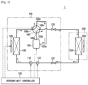
- FIG. 1 is a conceptual view illustrating a system of an air conditioner according to an embodiment of the present invention inter alia comprising sensors and a controller configuration as defined in appended independent claim 1.
- the air conditioner 1 includes an outdoor unit 100 to perform heat exchange between outdoor air and refrigerant and an indoor unit 200 to perform heat exchange between indoor air and refrigerant.
- the indoor unit 200 and the outdoor unit 100 are coupled to each other through a refrigerant pipe, resulting in formation of a cycle.
- the outdoor unit 100 may include a high-pressure service valve 120 and a low-pressure service valve 122 that are used to perform coupling of the refrigerant pipe connected to the indoor unit 200.
- the outdoor unit 100 includes a compressor 102, a flow passage switching valve 106, an outdoor heat exchanger 108, a first expansion valve 110, and a second expansion valve 112.
- the compressor 102 forms high-temperature high-pressure refrigerant by compressing low-temperature low-pressure refrigerant suctioned through an inlet 102a, and may discharge the high-temperature high-pressure refrigerant to the outside through an outlet 102b
- the compressor 102 is constructed as a variable RPM rotary compressor in which compression capacity may be changed according to an input frequency.
- the compressor 102 may be implemented as a low-capacity variable RPM rotary compressor having a displacement of 9 ⁇ 12cc/rev.
- the inlet 102a and the outlet 102b of the compressor 102 may be connected to the flow passage switching valve 106.
- the flow passage switching valve 106 may be constructed as a 4-way valve to switch flow of refrigerant discharged from the compressor 102 according to an operation mode ( cooling or heating), resulting in formation of a refrigerant flow passage needed to perform the corresponding operation mode.
- the flow passage switching valve 106 may include a first port 106a connected to the outlet 102b of the compressor 100, a second port 106b connected to the outdoor heat exchanger 108, a third port 106c connected to the indoor unit 200, and a fourth port 106d connected to the inlet 102a of the compressor 100.
- the outdoor heat exchanger 108 operates as a condenser for condensing a high-temperature high-pressure gaseous refrigerant into a normal-temperature high-pressure liquid refrigerant.
- the outdoor heat exchanger 108 operates as an evaporator for evaporating a low temperature low-pressure liquid refrigerant into a gaseous refrigerant, such that the outdoor heat exchanger 108 may perform heat exchange with peripheral air in response to change in refrigerant enthalpy.
- the first expansion valve 110 and the second expansion valve 112 are connected to one side of the outdoor heat exchanger 108.
- the outdoor heat exchanger 108 may include an outdoor fan 109 configured to increase the efficiency of heat exchange between refrigerant and outdoor air.
- Each of the first expansion valve 110 and the second expansion valve 112 are implemented as an electronic expansion valve configured to adjust the degree of opening thereof.
- the first expansion valve 110 and the second expansion valve 112 expand the refrigerant, adjust a flow rate of the refrigerant, and may prevent flow of the refrigerant.
- the first expansion valve 110 decompresses a high-pressure refrigerant
- the second expansion valve 112 decompresses a medium-pressure refrigerant.
- the embodiment of the present disclosure connects the first expansion valve 110 and the second expansion valve 112 in series so as to implement the multistage expansion scheme, such that the embodiment may acquire an optimum compression ratio in all the cooling/heating load regions.
- the multistage expansion scheme is configured in a manner that legacy electronic expansion valves are simply connected in series, such that the number of design modifications, such as the design modification of the outdoor heat exchanger 108, as compared to the conventional design may be minimized.
- the indoor unit 200 may be an apparatus for cooling/heating indoor air of the indoor space through heat exchange between the refrigerant and the air.
- the indoor unit 200 includes an indoor heat exchanger 202 and may include an indoor fan 203. If necessary, two or more indoor units 200 may also be installed.
- the indoor heat exchanger 202 operates as the evaporator in the cooling mode, and operates as the condenser in the heating mode.
- the indoor fan 203 may be installed adjacent to the indoor heat exchanger 202, and may circulate indoor air, such that the indoor fan 203 may increase the efficiency of heat exchange between the refrigerant circulating in the indoor heat exchanger 202 and the indoor air.
- the refrigerant for transferring indoor heat energy to the outdoor space or transferring outdoor heat energy to the indoor space using the air conditioner 1 will hereinafter be described in detail.
- RFC-based R 410 A refrigerants generally used in most household air conditioners have a high GWP causing global warming, such that the RFC-based R 410 A refrigerants are normally subject to international regulation.
- the same RFC-based R 32 refrigerants having a low GWP have been increasingly used as alternative refrigerants in associated industries.
- the R 32 refrigerant having a low GWP may have a relatively large specific volume and lower density, resulting in reduction of a mass flow rate.
- the R32 refrigerant has superior cooling capability per unit mass, such that it is expected that the R32 refrigerant has 2-3% higher performance as compared to the R410A refrigerant.
- variable-RPM compressor 102 should have a low RPM, such that the part-load condition may refer to a section in which the compression ratio is gradually reduced.
- the normal cycle In order to normally perform a refrigerant evaporation process through heat exchange with the air under the corresponding condition, the normal cycle must be achieved by reducing evaporation saturation pressure through reduction of the degree of opening of the expansion valve.
- the multistage expansion scheme is implemented instead of the legacy 1-stage expansion scheme, and a normal cycle is implemented in a low-flow-rate condition, such that the performance and reliability can be guaranteed.
- the above-mentioned multistage expansion scheme is implemented by simply connecting the legacy expansion valves in series, such that the number of design modifications can be minimized as compared to the number of design modifications of the heat exchanger.
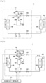
- FIG. 2 is a conceptual diagram illustrating a refrigerant cycle during a cooling mode of the air conditioner shown in FIG. 1 .
- an outdoor-unit controller 130 may connect the first port 106a to the second port 106b by operating the flow passage switching valve 106, and may form a refrigerant flow passage connected to the third port 106c and the fourth port 106d.
- the outdoor-unit controller 130 may open the first expansion valve 110 and the second expansion valve 112, and may thus control the refrigerant to flow into the indoor unit 200.
- the refrigerant discharged from the compressor 102 may flow into the indoor unit 200 after passing through the flow passage switching valve 106 and the outdoor heat exchanger 108.
- the outdoor heat exchanger 108 may operate as the condenser.
- the refrigerant flowing in the indoor unit 200 may be suctioned into the compressor 102 after sequentially passing through the indoor heat exchanger 202 and the flow passage switching valve 106.
- the indoor heat exchanger 202 may operate as the evaporator.
- the air conditioner 1 may construct the refrigerant cycle in which the refrigerant circulates in the order of the compressor 102 ⁇ the flow passage switching valve 106 ⁇ the outdoor heat exchanger 108 ⁇ the first expansion valve 110 ⁇ the second expansion valve 112 ⁇ the indoor heat exchanger 202 ⁇ the flow passage switching valve 106 ⁇ the compressor 102, resulting in implementation of the cooling mode of the indoor unit 200.
- FIG. 3 is a conceptual diagram illustrating a refrigerant cycle during the heating mode of the air conditioner shown in FIG. 1 .
- the outdoor-unit controller 130 may connect the first port 106a to the third port 106c by operating the flow passage switching valve 106, and may form a refrigerant flow passage connected to the second port 106b and the fourth port 106d.
- the outdoor-unit controller 130 may open the first expansion valve 110 and the second expansion valve 112, and may thus control the refrigerant to flow in the indoor unit 200.
- the refrigerant discharged from the compressor 102 may flow in the indoor unit 200 after passing through the flow passage switching valve 106.
- the refrigerant flowing in the indoor unit 200 may flow into the outdoor heat exchanger 108 after passing through the outdoor heat exchanger 202.
- the indoor heat exchanger 202 may operate as the condenser
- the outdoor heat exchanger 108 may operate as the evaporator.
- the refrigerant flowing in the outdoor heat exchanger 108 may be suctioned into the compressor 102 after passing through the flow passage switching valve 106.
- the air conditioner 1 may construct the refrigerant cycle in which the refrigerant circulates in the order of the compressor 102 ⁇ the flow passage switching valve 106 ⁇ the indoor heat exchanger 202 ⁇ the second expansion valve 112 ⁇ the first expansion valve 110 ⁇ the outdoor heat exchanger 108 ⁇ the flow passage switching valve 106 ⁇ the compressor 102, resulting in implementation of the heating mode of the indoor unit 200.
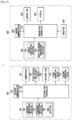
- FIG. 4 is a block diagram illustrating a control system of the air conditioner shown in FIG. 1 .
- the outdoor unit 100 of the air conditioner 1 may include not only the constituent elements shown in FIG. 1 , but also the outdoor-unit controller 130, a detector 140, and an outdoor communicator 150.
- the outdoor-unit controller 130 may be a microprocessor for controlling overall operation of the outdoor unit 100.
- the outdoor-unit controller 130 may receive various kinds of information needed to operate the outdoor unit 100 from the detector 140, and may control the compressor 102, the flow passage switching valve 106, the first expansion valve 110, and the second expansion valve 112 on the basis of the received information.
- the outdoor-unit controller 130 may include a memory in which the initial opening degree of each of the first expansion valve 110 and the second expansion valve 112 according to outdoor air (T o ) and a compressor RPM (C f ) is preset.
- the detector 140 may detect various kinds of information needed to operate the outdoor unit 100 from sensors mounted to the outdoor unit 100, may output the detected information to the outdoor-unit controller 130, and includes an outdoor temperature detector 142, a discharge-temperature detector 144, and a RPM detector 146.
- the outdoor-temperature detector 142 detects a temperature (T o ) of the outdoor space including the outdoor unit 100, and outputs the detected temperature (T o ) to the outdoor-unit controller 130.
- the discharge-temperature detector 144 detects a refrigerant temperature (T d ) of the outlet 102b of the compressor 102, and outputs the detected refrigerant temperature (T d ) to the outdoor-unit controller 130.
- the RPM detector 1462 detects the RPM (C f ) of the compressor 102, and outputs the detected RPM (C f ) of the compressor 102 to the controller 130.
- the outdoor communicator 150 may be connected to the outdoor-unit controller 130, and may communicate with the indoor unit 200.
- the indoor unit 200 of the air conditioner 1 may include not only the constituent elements shown in FIG. 1 , but also an indoor-unit controller 210, a detector 220, an inputter 230, a display 232, and an indoor communicator 234.
- the indoor-unit controller 210 may be a microprocessor for controlling overall operation of the indoor unit 200.
- the indoor-unit controller 210 may receive various kinds of information needed to operate the indoor unit 200 from the detector 220, and may control the indoor unit 200 on the basis of the received information.
- the detector 220 may detect various kinds of information needed to operate the indoor unit 200 from sensors mounted to the indoor unit 200, may output the detected information to the indoor-unit controller 210, and may include an indoor-temperature detector 222 and a heat-exchanger temperature detector 224.
- the indoor-temperature detector 222 may detect a temperature (T r ) of the indoor space including the indoor unit 200, and may output the detected temperature (T r ) to the indoor-unit controller 210.
- the heat-exchanger temperature detector 224 may detect a temperature of the indoor heat-exchanger 202, and may output the detected temperature to the indoor-unit controller 210.
- the inputter 230 may be a remote control device for wirelessly transmitting a control command for selecting an operation of the indoor unit 200, and may select any one of the cooling mode and the heating mode.
- the inputter 230 may include a mobile phone (e.g., a cellular phone or a PCS phone), a smartphone, a personal digital assistant (PDA), a Portable Multimedia Player (PMP), a laptop computer, a digital broadcasting terminal, a netbook, a tablet PC, a navigation system, etc.
- a mobile phone e.g., a cellular phone or a PCS phone
- PDA personal digital assistant
- PMP Portable Multimedia Player
- laptop computer e.g., a laptop computer
- PDA personal digital assistant
- PMP Portable Multimedia Player
- the inputter 230 may be a general simplified remote-controller.
- the remote-controller may generally communicate with the indoor unit 200 using infrared Data Association (IrDA).
- IrDA infrared Data Association
- the inputter 230 may transmit and receive radio frequency (RF) signals to and from the indoor unit 200 using various communication schemes, for example, Radio Frequency (RF), Wi-Fi, Bluetooth, ZigBee), Near Field Communication (NFC), Ultra Wide Band (UWB), etc. It should be noted that any one of the above communication schemes through which the inputter 216 transmits and receives RF signals to and from the indoor unit 200 through wireless communication can be applied to the present disclosure without departing from the scope or spirit of the present disclosure.
- RF Radio Frequency
- Wi-Fi Wireless Fidelity
- Bluetooth ZigBee
- NFC Near Field Communication
- UWB Ultra Wide Band
- the inputter 230 may include an operation/stop button to turn on or off the indoor unit 200, an operation selection button to select an operation mode of the indoor unit 200, a wind-direction button to control the direction of airflow, an air-volume button to control the intensity of airflow, a temperature button to adjust a temperature, a dial button, etc.
- the air conditioner 1 may perform the heating mode or the cooling mode according to a mode selection command of the inputter 230.
- the display 232 may display operation states of the indoor unit 200 according to a control signal of the indoor-unit controller 210.
- the indoor communicator 234 may be connected to the indoor-unit controller 210, and may communicate with the outdoor unit 100.
- the outdoor-unit controller 130 and the indoor-unit controller 210 may be connected to a power supply (not shown), and may receive a power source from the power supply (not shown).
- the outdoor-unit controller 130 and the indoor-unit controller 210 may be integrated into one body, and may thus control the indoor-unit controller 210.
- FIG. 5 is a graph illustrating a 2-stage expansion process based on two expansion valves for use in a P-H diagram of the air conditioner according to an embodiment of the present disclosure.
- the first expansion valve 110 is provided to decompress a supercooled refrigerant generated from an outlet of the condenser (i.e., the outdoor heat-exchanger) to a two-phase region in which gaseous refrigerant and liquid refrigerant are mixed with each other, and the second expansion valve 112 is provided to decompress a two-phase refrigerant having medium pressure to an evaporation pressure after the two-phase refrigerant has passed through the first expansion valve 110.
- the condenser i.e., the outdoor heat-exchanger
- the first expansion valve 110 is provided to operate as the second expansion valve 112
- the second expansion valve 112 is provided to J operate as the first expansion valve 110.
- the air conditioner according to the present invention determines a medium-pressure point by adjusting the degree of opening of the first expansion valve 110, and determines an evaporation pressure by adjusting the degree of opening of the second expansion valve 112, such that the air conditioner may control the compression ratio.
- the air conditioner 1 If the optimum compression ratio is not guaranteed in the air conditioner 1, sensible heat capability of the air is reduced, and a specific enthalpy (i.e., enthalpy per unit mass) of the refrigerant is reduced, resulting in reduction of the cooling/heating capability.
- enthalpy i.e., enthalpy per unit mass
- the degree of superheat is not guaranteed in the inlet 102 of the compressor 102, such that the possibility of liquid compression may increase and the reliability problem may occur.
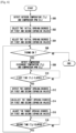
- FIG. 6 is a flowchart illustrating a first control algorithm based on a multistage expansion scheme for use in an air conditioner according to the present invention as defined by appended independent claim 1.
- the first control algorithm shown in FIG. 6 will disclose a method for controlling the degree of opening of each of the first and second expansion valves 110 and 112 according to the outdoor/indoor load conditions in such a manner that the flow rate and the compression rate can be optimally adjusted although refrigerants having different physical properties are used using the multistage expansion scheme in which the first expansion valve 110 and the second expansion valve 112 are connected in series.
- the operation mode of the air conditioner 1 will hereinafter be described centering upon the cooling mode.
- the selected cooling mode information may be input to the indoor-unit controller 210.
- the user may input a desired set temperature (T s ) through the inputter 230.
- the indoor-unit controller 210 may operate the indoor fan 203 according to the user-selected cooling mode information.
- the indoor-unit controller 210 may communicate with the outdoor communicator 150 of the outdoor unit 100 through the indoor communicator 234, and the outdoor-unit controller 130 may receive the user-selected cooling mode information from the indoor-unit controller 210, such that the indoor-unit controller 210 may sequentially operate the outdoor fan 109 and the compressor 102.
- the outdoor-unit controller 130 may operate the flow passage switching valve 106 according to the user-selected cooling mode information, and may control the refrigerant to circulate in the cycle shown in FIG. 2 , such that the cooling mode starts operation.
- the outdoor-temperature detector 142 may detect the temperature (T o ) of the outdoor space including the outdoor unit 100, and may output the detected temperature (T o ) to the outdoor-unit controller 130.
- the RPM detector 146 may detect the RPM (C f ) of the compressor 102, and may output the detected RPM (C f ) of the outdoor-unit controller 130 (300). If the cooling mode is operated according to the present invention, all of these detecting and outputting steps are actually carried out.
- the outdoor-unit controller 130 selects the initial opening degree of each of the first expansion valve 110 and the second expansion valve 112 not only using the outdoor temperature (T o ) detected by the outdoor-temperature detector 142, but also using the compressor RPM (C f ) detected by the RPM detector 146 (302).
- the outdoor-unit controller 130 Since the initial opening degree of the first expansion valve 110 and the initial opening degree of the second expansion valve 112 are preset in the outdoor-unit controller 130 according to the outdoor temperature (T o ) and the compressor RPM (C f ), the outdoor-unit controller 130 selects the initial opening degree of the first expansion valve 110 and the initial opening degree of the second expansion valve 112 according to the outdoor temperature (T o ) detected by the outdoor-temperature detector 142 and the compressor RPM (C f ) detected by the RPM detector 146.
- the controller 130 selects the initial opening degree of each of the first and second expansion valves 110 and 112 using at least two and optionally three detection values, i.e., optionally the indoor temperature (T r ), and always the outdoor temperature (T o ), and the compressor RPM (C f ).
- the outdoor-unit controller 130 is operated to open or close the first expansion valve 110 and the second expansion valve 112 using the selected initial opening degree, such that the outdoor-unit controller 130 may adjust the first expansion valve 110 and the second expansion valve 112 using the initial opening degree (304).
- the outdoor-unit controller 130 may determine whether a thermo-ON condition is provided (306).
- the thermo-ON condition may refer to a process for determining a startup condition of the compressor 102 by comparing a temperature (i.e., the indoor temperature T r ) of the indoor space including the indoor unit 200 with the set temperature (T s ). For example, if the indoor temperature (T r ) does not reach the set temperature (T s ), it is necessary for the compressor 102 to be continuously turned on, such that this condition will hereinafter be referred to as a thermo-ON condition. If the indoor temperature (T r ) reaches the set temperature (T s ), it is necessary for the compressor 102 to be turned off, such that this condition will hereinafter be referred to as a thermo-OFF condition.
- the outdoor-unit controller 130 may determine that the thermo-OFF condition in which the indoor temperature (T r ) reaches the set temperature (T s ) has been provided, such that the air conditioner 1 stops operation.
- the outdoor-unit controller 130 may detect a refrigerant temperature (T d ) at the outlet 102b of the compressor 102 through the discharge temperature detector 144, and may detect the RPM (Cf) of the compressor 102 through the RPM detector 146 (308).
- the outdoor-unit controller 130 may determine whether a first time (t 1 ) (for example, several milliseconds (ms), corresponding to a sensing period for detecting the compressor discharge temperature T d and the compressor RPM C f ), has elapsed (310).
- a first time for example, several milliseconds (ms), corresponding to a sensing period for detecting the compressor discharge temperature T d and the compressor RPM C f )
- the discharge temperature detector 144 may repeatedly detect, in real time, the refrigerant temperature (T d ) at the outlet 102b of the compressor 102 at intervals of the sensing period (t i ), and may output the detected refrigerant temperature (T d ) to the outdoor-unit controller 130.
- the RPM detector 146 may repeatedly detect, in real time, the RPM (C f ) of the compressor 102 at intervals of the sensing period (t l ), and may output the detected RPM (C f ) of the compressor 102 to the outdoor-unit controller 130 (308).
- the outdoor-unit controller 130 may store not only the compressor discharge temperature (T d ) detected at intervals of the sensing period (t l ), but also the compressor RPM (C f ).
- the outdoor-unit controller 130 may detect the degree of current opening of each of the first expansion valve 110 and the second expansion valve 112 (312).
- the outdoor-unit controller 130 may compare the previously-stored compressor discharge temperature (T d ) and the previously-stored compressor RPM (C f ) with the current compressor discharge temperature (T d ) and the current compressor RPM (C f ), such that the outdoor-unit controller 130 may determine the opened or closed state on the basis of the current opening degree of each of the first and second expansion valves 110 and 112, and may calculate a target degree of opening of each of the first and second expansion valves 110 and 112 (314).
- the compressor discharge temperature (T d ) is a significant factor for deciding a specific enthalpy in the cooling/heating cycles
- the compressor RPM (C f ) is a significant factor for changing the specific enthalpy and the flow rate. Therefore, the target opening degree of the first expansion valve 110 and the target opening degree of the second expansion valve 112 may be calculated using two factors, resulting in decision of the 2-stage expansion degree.
- the outdoor-unit controller 130 may open or close the first expansion valve 110 and the second expansion valve 112 by the calculated target opening degree, such that the first expansion valve 110 and the second expansion valve 112 can be adjusted using the target opening degree (316).
- the first expansion valve 110 and the second expansion valve 112 may be controlled to follow the same opening degree calculated at the same time point. That is, the multistage expansion scheme according to the present disclosure may be controlled in a manner that the first expansion valve 110 and the second expansion valve 112 can always maintain the same opening degree.
- the outdoor-unit controller 130 may determine whether a second time (t 2 ) (for example, about 1 ⁇ 2 minutes, corresponding to the opening degree control period in which the degree of opening of each of the first expansion valve and the second expansion valve is changed to optimize the cycle changed according to the outdoor/indoor load conditions), has elapsed (318).
- a second time for example, about 1 ⁇ 2 minutes, corresponding to the opening degree control period in which the degree of opening of each of the first expansion valve and the second expansion valve is changed to optimize the cycle changed according to the outdoor/indoor load conditions
- the outdoor-unit controller 130 may feedback to operation 306, may determine that the thermo-ON condition for determining whether the compressor 102 starts operation is provided, is operated to re-detect the compressor discharge temperature (T d ) and the compressor RPM (C f ), and repeatedly perform subsequent processes at intervals of a predetermined time.
- FIG. 7 is a flowchart illustrating a second control algorithm based on a multistage expansion scheme for use in the air conditioner according to the invention as defined by appended independent claim 1.
- the selected cooling mode information may be input to the indoor-unit controller 210.
- the user may input a desired set temperature (T s ) through the inputter 230.
- the indoor-unit controller 210 may operate the indoor fan 203 according to the user-selected cooling mode information.
- the indoor-unit controller 210 may communicate with the outdoor communicator 150 of the outdoor unit 100 through the indoor communicator 234, the outdoor-unit controller 130 may receive the user-selected cooling mode information from the indoor-unit controller 210, and may thus sequentially operate the outdoor fan 109 and the compressor 102.
- the outdoor-unit controller 130 may operate the flow passage switching valve 106 according to the user-selected cooling mode information, and may control the refrigerant to circulate in the cycle of FIG. 2 , such that the cooling mode may start operation.
- the outdoor-temperature detector 142 detects the temperature (T o ) of the outdoor space including the outdoor unit 100, and may output the detected outdoor temperature (T o ) to the outdoor-unit controller 130.
- the RPM detector 146 may detect the RPM (C f ) of the compressor 102, and may thus output the detected RPM (C f ) to the outdoor-unit controller 130 (400). In an actual operation of an inventive system defined by appended independent claim 1, all these detecting and outputting steps are performed.
- the outdoor-unit controller 130 selects the initial opening degree of each of the first expansion valve 110 and the second expansion valve 112 not only using the outdoor temperature (T o ) detected by the outdoor-temperature detector 142, but also using the compressor RPM (C f ) detected by the RPM detector 146 (402).
- the initial opening degree of the first expansion valve 110 and the initial opening degree of the second expansion valve 112 are preset in the outdoor-unit controller 130 according to the outdoor temperature (T o ) and the compressor RPM (C f ), the initial opening degree of the first expansion valve 110 and the initial opening degree of the second expansion valve 112 may be selected according to the outdoor temperature (T o ) detected by the outdoor-temperature detector 142 and the compressor RPM (C f ) detected by the RPM detector 146.
- the outdoor-unit controller 130 may also select the initial opening degree using three detection values, i.e., the indoor temperature (T r ), the outdoor temperature (T o ), and the compressor RPM (C f ).
- T r the indoor temperature
- T o the outdoor temperature
- C f the compressor RPM
- the outdoor-unit controller 130 is operated to open or close the first expansion valve 110 and the second expansion valve 112 according to the selected initial opening degree, such that the outdoor-unit controller 130 may control each of the first expansion valve 110 and the second expansion valve 112 using the initial opening degree (404).
- the outdoor-unit controller 130 may determine whether the thermo-ON condition is provided (406).
- the outdoor-unit controller 130 may determine that the thermo-OFF condition in which the indoor temperature (T r ) reaches the set temperature (T s ) is provided, and may thus stop operation of the air conditioner 1.
- the outdoor-unit controller 130 may detect the refrigerant temperature (Td) at the outlet 102b of the compressor 102 through the discharge temperature detector 144, and may detect the RPM (C f ) of the compressor 102 through the RPM detector 146 (408).
- the outdoor-unit controller 130 may determine whether the first time (t 1 ) has elapsed (410).
- the discharge temperature detector 144 may repeatedly detect, in real time, the refrigerant temperature (T d ) at the outlet 102b of the compressor 102 at intervals of the sensing period (t i ), and may output the detected refrigerant temperature (T d ) to the outdoor-unit controller 130.
- the RPM detector 146 may repeatedly detect, in real time, the RPM (C f ) of the compressor 102 at intervals of the sensing period (t l ), and may output the detected RPM (C f ) of the compressor 102 to the outdoor-unit controller 130 (308).
- the outdoor-unit controller 130 may store not only the compressor discharge temperature (T d ) detected at intervals of the sensing period (t i ), but also the compressor RPM (C f ).
- the outdoor-unit controller 130 detects the outdoor temperature (T o ) through the outdoor-temperature detector 142 and detects the indoor temperature (T r ) through the indoor-temperature detector 222 so as to calculate the target opening degree of the first expansion valve 110 (412).
- the reason why the outdoor temperature (T o ) and the indoor temperature (T r ) are detected is to adjust the medium pressure after completion of 1-stage expansion through regulation of the degree of opening of the first expansion valve 110 in consideration of the indoor/ outdoor loads.
- the optimum compression ratio for optimizing the cycle according to the indoor/outdoor loads is changed, such that it is necessary to control the flow rate in consideration of the indoor/outdoor loads through detection of the outdoor temperature (T o ) and the indoor temperature (T r ).
- the outdoor-unit controller 130 may detect a current opening degree of the first expansion valve 110 (414), may determine the opened or closed state of the first expansion valve 110 on the basis of the current opening degree using the detected outdoor temperature (T o ) and the indoor temperature (T r ), and may calculate the target opening degree of the first expansion valve 110 (416).
- the outdoor-unit controller 130 may open or close the first expansion valve 110 by the calculated target opening degree, such that the first expansion valve 110 is adjusted using the target opening degree (418).
- the outdoor-unit controller 130 may determine whether a third time (t 3 ) (for example, about 1 ⁇ 2 minutes, corresponding to the opening degree control period in which the degree of opening of the first expansion valve is changed to optimize the cycle changed according to the outdoor/indoor load conditions), has elapsed (420).
- a third time for example, about 1 ⁇ 2 minutes, corresponding to the opening degree control period in which the degree of opening of the first expansion valve is changed to optimize the cycle changed according to the outdoor/indoor load conditions
- the outdoor-unit controller 130 may feed back to operation 406, may determine that the thermo-ON condition for determining whether the compressor 102 starts operation is provided, is operated to re-detect the compressor discharge temperature (T d ) and the compressor RPM (C f ), and repeatedly perform subsequent processes at intervals of a predetermined time, such that the degree of opening of the first expansion valve 110 is controlled. In this case, the opening degree change period of the first expansion valve 110 may be changed as necessary.
- the outdoor-unit controller 130 may detect the current opening degree of the second expansion valve 112 (430), may determine the opened or closed state of the second expansion valve 112 on the basis of the current opening degree in consideration of the compressor discharge temperature (T d ) and the compressor RPM (C f ), and may calculate the target opening degree of the second expansion valve 112 (432).
- the compressor discharge temperature (T d ) is a significant factor for deciding a specific enthalpy in the cooling/heating cycles
- the compressor RPM (C f ) is a significant factor for changing the specific enthalpy and the flow rate. Therefore, the target opening degree of the second expansion valve 112 may be calculated using two factors, resulting in decision of the 2-stage expansion degree.
- the outdoor-unit controller 130 may open or close the second expansion valve 112 by the calculated target opening degree, and may adjust the second expansion valve 112 using the target opening degree (434).
- the indoor-unit controller 130 may determine whether the second time (t 2 ) (for example, about 1 ⁇ 2 minutes, corresponding to the opening degree control period in which the degree of opening of the second expansion valve is changed to optimize the cycle changed according to the outdoor/indoor load conditions), has elapsed (436).
- the second time (t 2 ) for example, about 1 ⁇ 2 minutes, corresponding to the opening degree control period in which the degree of opening of the second expansion valve is changed to optimize the cycle changed according to the outdoor/indoor load conditions
- the outdoor-unit controller 130 may feed back to operation 406, may determine that the thermo-ON condition for determining whether the compressor 102 starts operation is provided, may re-detect the compressor discharge temperature (T d ) and the compressor RPM (C f ), and may repeatedly perform subsequent processes at intervals of a predetermined time. Accordingly, the degree of opening of the second expansion valve 112 may be controlled. In this case, the opening degree change period of the second expansion valve 112 may be changed as necessary.
- the superheat degree of cooling may be calculated by detecting a temperature at each of the inlet and outlet of the evaporator of the indoor-unit heat exchanger 202, a medium temperature of the evaporator, and a temperature at the inlet of the compressor 102, such that the optimum compression ratio can be guaranteed through the scheme for controlling the cooling opening degree needed to estimate a specific superheat degree.
- FIG. 8 is a flowchart illustrating a third control algorithm based on a multistage expansion scheme for use in the air conditioner according to the invention as defined by appended independent claim 1.
- the selected cooling mode information is input to the indoor-unit controller 210.
- the user may input a desired set temperature (T s ) through the inputter 230.
- the indoor-unit controller 210 may operate the indoor fan 203 according to the user selected cooling mode information.
- the indoor-unit controller 210 may communicate with the outdoor communicator 150 of the outdoor unit 100 through the indoor communicator 234, may receive the user-selected cooling mode information from the indoor-unit controller 210, and may sequentially operate the outdoor fan 109 and the compressor 102.
- the outdoor-unit controller 130 may operate the flow passage switching valve 106 according to the user-selected cooling mode information, and may control the refrigerant to circulate in the cycle of FIG. 2 , thereby starting the cooling mode.
- the outdoor-temperature detector 142 may detect the temperature (T o ) of the outdoor space including the outdoor unit 100, and may output the detected temperature (T o ) to the outdoor-unit controller 130.
- the RPM detector 146 may detect the RPM (C f ) of the compressor 102, and may thus output the detected RPM (C f ) to the outdoor-unit controller 130 (500). When operating a system according to the present invention, all these detecting and outputting steps are actually performed.
- the outdoor-unit controller 130 selects the degree of initial opening of each of the first expansion valve 110 and the second expansion valve 112 not only using the outdoor temperature (T o ) detected by the outdoor-unit detector 142, but also using the compressor RPM (C f ) detected by the RPM detector 146 (502).
- the initial opening degree of the first expansion valve 110 and the initial opening degree of the second expansion valve 112 are preset in the outdoor-unit controller 130 according to the outdoor temperature (T o ) and the compressor RPM (C f ), the initial opening degree of the first expansion valve 110 and the initial opening degree of the second expansion valve 112 may be selected according to the outdoor temperature (T o ) detected by the outdoor-temperature detector 142 and the compressor RPM (C f ) detected by the RPM detector 146.
- the outdoor-unit controller 130 may also select the degree of initial opening using three detection values, i.e., the indoor temperature (T r ), the outdoor temperature (T o ), and the compressor RPM (C f where the latter two values are always used in the context of the present invention
- the outdoor-unit controller 130 is operated to open or close the first expansion valve 110 and the second expansion valve 112 according to the selected initial opening degree, such that the outdoor-unit controller 130 is operated to adjust the degree of initial opening of each of the first expansion valve 110 and the second expansion valve 112 (504).
- the outdoor-unit controller 130 may determine whether the thermo-ON condition is provided (506).
- the outdoor-unit controller 130 may determine that the thermo-OFF condition in which the indoor temperature (T r ) reaches the set temperature (T s ) is provided, and may stop operation of the air conditioner 1.
- the outdoor-unit controller 130 may detect the refrigerant temperature (T d ) at the outlet 102b of the compressor 102 through the discharge temperature detector 144, and may detect the RPM (C f ) of the compressor 102 through the RPM detector 146 (508).
- the outdoor-unit controller 130 may determine whether the first time (t 1 ) has elapsed (510).
- the discharge temperature detector 144 may repeatedly detect, in real time, the refrigerant temperature (T d ) at the outlet 102b of the compressor 102 at intervals of the sensing period (t i ), and may output the detected refrigerant temperature (T d ) to the outdoor-unit controller 130.
- the RPM detector 146 may repeatedly detect, in real time, the RPM (C f ) of the compressor 102 at intervals of the sensing period (t l ), and may output the detected RPM (C f ) of the compressor 102 to the outdoor-unit controller 130 (308).
- the outdoor-unit controller 130 may store not only the compressor discharge temperature (T d ) detected at intervals of the sensing period (t l ), but also the compressor RPM (C f ).
- the outdoor-unit controller 130 may detect the current opening degree of the first expansion valve 110 (512), may determine the opened or closed state of the first expansion valve 110 on the basis of the current opening degree, and may calculate the target opening degree of the first expansion valve 110 (514).
- the compressor discharge temperature (T d ) is a significant factor for deciding a specific enthalpy in the cooling/heating cycles
- the compressor RPM (C f ) is a significant factor for changing the specific enthalpy and the flow rate. Therefore, the target opening degree of the first expansion valve 110 may be calculated using two factors, resulting in decision of the 1-stage expansion degree.
- the outdoor-unit controller 130 may open or close the first expansion valve 110 by the calculated target opening degree, and may thus control the first expansion valve 110 using the target opening degree (516).
- the outdoor-unit controller 130 may determine whether the third time (t 3 ) has elapsed (518).
- the outdoor-unit controller 130 may feed back to operation 506, may determine that the thermo-ON condition for determining whether the compressor 102 starts operation is provided, may re-detect the compressor discharge temperature (T d ) and the compressor RPM (C f ), and may repeatedly perform subsequent processes at intervals of a predetermined time. Therefore, the degree of opening of the first expansion valve 110 may be controlled. In this case, the opening degree change period of the first expansion valve 110 may be changed as necessary.
- the outdoor-unit controller 130 detects the outdoor temperature (T o ) through the outdoor-temperature detector 142 and detects the indoor temperature (T r ) through the indoor-temperature detector 222 so as to calculate the target opening degree of the second expansion valve 112 (530).
- the reason why the outdoor temperature (T o ) and the indoor temperature (T r ) are detected is to adjust the medium pressure after completion of 2-stage expansion through regulation of the degree of opening of the second expansion valve 112 in consideration of the indoor/ outdoor loads.
- the optimum compression ratio for optimizing the cycle according to the indoor/outdoor loads is changed, such that it is necessary to control the flow rate in consideration of the indoor/outdoor loads through detection of the outdoor temperature (T o ) and the indoor temperature (T r ).
- the outdoor-unit controller 130 may detect the current opening degree of the second expansion valve 112 (532), may determine the opened or closed state of the second expansion valve 112 on the basis of the current opening degree using the detected outdoor temperature (T o ) and the indoor temperature (T r ), and may calculate the target opening degree of the second expansion valve 112 (534).
- the outdoor-unit controller 130 may open or close the second expansion valve 112 by the calculated target opening degree, such that the second expansion valve 112 is adjusted using the target opening degree (536).
- the outdoor-unit controller 130 may determine whether the second time (t 2 ) has elapsed (538).
- the outdoor-unit controller 130 may feed back to operation 506, may determine that the thermo-ON condition for determining whether the compressor 102 starts operation is provided, may re-detect the compressor discharge temperature (T d ) and the compressor RPM (C f ), and may repeatedly perform subsequent processes at intervals of a predetermined time, such that the degree of opening of the second expansion valve 112 is controlled. In this case, the opening degree change period of the second expansion valve 112 may be changed as necessary.
- FIG. 9 is a view illustrating the change of a cycle implemented when the multistage expansion - based expansion valve is used in the air conditioner after R32 refrigerant is applied to the air conditioner according to an embodiment of the present disclosure.
- the cooling capacity of 1 kW (3,500 BTU/h) may be similar to cooling capacity capable of being obtained when the compressor 102 having capacity of 9 ⁇ 12cc/rev is driven at a minimum RPM, and the partial load condition may be a significant load region for deciding a seasonal efficiency of the air conditioner 1.
- the essential constituent elements requisite for the cycle may be similar to the specifications shown in FIG. 1 , and only one expansion valve may be identical in structure to the legacy 410A refrigerant application system. When only one expansion valve identical to those of the related art is applied, the compression ratio is set to about 1.4.
- the compression ratio is set to about 1.6, such that it can be recognized that the compression ratio of the case of using two expansion valves is superior to the compression ratio of the other case of using only one expansion valve by about 15%.
- the refrigerant After the completion of 1-stage expansion, the refrigerant enters the two-phase region, and then enters the 2-stage expansion process, such that it can be recognized that evaporation pressure is greatly reduced as compared to application of a single expansion valve, and total capability is improved by 10% or higher.
- the appropriate pressure can be guaranteed even in the region of 1 kW (3,500 BTU/h) or less, such that it can be recognized that desired performance is guaranteed in the part-load region.
- FIG. 10 is a graph illustrating the result of comparison of the opening degree according to the number of expansion valves when a R410A refrigerant and R32 refrigerant are applied in the same system having of predetermined cooling/heating load conditions (minimum/rated/maximum).
- minimum capacity is estimated as a capacity level of about 30% on the basis of the rated capacity, and testing of maximum capacity is performed at a capacity level of about 120% on the basis of the rated capacity.
- the reference for selecting the degree of opening may indicate the degree of opening under the state of cycle optimization, and may indicate the ratio of the opening degree to the full opening degree as a percentage %.
- the model having the range of warranty corresponding to a minimum opening degree ratio of about 16% is applied to the above expansion valves.
- the opening degree ratio is linearly increased in proportion to the increasing cooling/heating load.
- EOV expansion valve
- the optimum opening degree equal to or less than the minimum opening degree guaranteed by the expansion valves in the minimum cooling/heating load condition is formed.
- the optimum opening degree is reduced to the minimum opening degree ratio even at the rated heating capacity.
- the air conditioner and the method for controlling the same may implement a multistage expansion scheme by implementing serial connection between electronic expansion valves in the R410A refrigerant - based air conditioner, and may thus guarantee an optimum compression ratio in all cooling/heating load regions. Therefore, although cycle characteristics are changed by changing R410A refrigerant to R32 refrigerant, the air conditioner according to the embodiment may optimize the cycle simply by controlling the degree of opening of electronic expansion valves.
Landscapes
- Engineering & Computer Science (AREA)
- Mechanical Engineering (AREA)
- General Engineering & Computer Science (AREA)
- Physics & Mathematics (AREA)
- Thermal Sciences (AREA)
- Air Conditioning Control Device (AREA)
- Chemical & Material Sciences (AREA)
- Combustion & Propulsion (AREA)
Claims (10)
- Klimaanlage (1), umfassend:einen Kompressor (102), der dazu konfiguriert ist, ein Kältemittel zu komprimieren;ein Strömungskanal-Schaltventil (106), das dazu konfiguriert ist, einen Kältemittelfluss entsprechend mindestens einem von jeweils einem Kühlmodus und einem Heizmodus umzuschalten;eine mehrstufige Expansionsvorrichtung, die dazu konfiguriert ist, das Kältemittel zu dekomprimieren, wobei der Kompressor ein Rotationskompressor mit variabler Drehzahl ist, der das Kältemittel als Betriebsfluid verwendet, unddie mehrstufige Expansionsvorrichtung ein erstes Expansionsventil (110), um einen Druck des Kältemittels zu dekomprimieren, wenn das Kältemittel ein Hochdruckkältemittel ist, und ein zweites Expansionsventil (112) beinhaltet, um den Druck des Kältemittels zu dekomprimieren, wenn das Kältemittel ein Mitteldruckkältemittel ist, wobei das erste Expansionsventil und das zweite Expansionsventil in Reihe geschaltet sind, um ein 2-stufiges Expansionsschema zu implementieren und eine Durchflussrate und einen Druck des Kältemittels durch Änderung von jeweils dem Öffnungsgrad des ersten Expansionsventils und dem Öffnungsgrad des zweiten Expansionsventils einzustellen;einen Austrittstemperaturdetektor (144), der dazu konfiguriert ist, eine Kältemitteltemperatur an einem Auslass des Kompressors zu detektieren;einen Detektor (146) von U/min, Umdrehungen pro Minute, der dazu konfiguriert ist, die U/min des Kompressors zu detektieren,einen Außentemperaturdetektor (142), der dazu konfiguriert ist, eine Außentemperatur zu detektieren;eine Steuerung (130), die dazu konfiguriert ist, einen anfänglichen Öffnungsgrad von jedem von dem ersten Expansionsventil und dem zweiten Expansionsventil als Reaktion auf die durch den Außentemperaturdetektor detektierte Außentemperatur und die durch den Detektor für U/min detektierte Kompressor-U/min auszuwählen;wobei die Steuerung ferner dazu konfiguriert ist, jeweils einen Öffnungsgrad des ersten Expansionsventils und einen Öffnungsgrad des zweiten Expansionsventils durch Detektieren der Kompressoraustrittstemperatur und der Kompressor-U/min in vorgegebenen Zeitintervallen zu steuern;wobei das Kältemittel R32-Kältemittel ist.
- Klimaanlage nach Anspruch 1, wobei die Steuerung ferner dazu konfiguriert ist, jeweils den Öffnungsgrad des ersten Expansionsventils und den Öffnungsgrad des zweiten Expansionsventils zu steuern, um in allen Lastbereichen von jeweils dem Kühlmodus und dem Heizmodus ein optimales Kompressionsverhältnis zu erreichen.
- Klimaanlage nach Anspruch 1 oder 2, ferner umfassend:einen Innentemperaturdetektor (222), der dazu konfiguriert ist, eine Innentemperatur zu detektieren,wobei die Steuerung den anfänglichen Öffnungsgrad des ersten Expansionsventils und des zweiten Expansionsventils als Reaktion auf die durch den Innentemperaturdetektor detektierte Innentemperatur, die durch den Außentemperaturdetektor detektierte Außentemperatur und die durch den Detektor von U/min detektierte Kompressor-U/min auswählt.
- Klimaanlage nach Anspruch 1, ferner umfassend:einen Detektor, der dazu konfiguriert ist, einen aktuellen Öffnungsgrad jeweils von dem ersten Expansionsventil und dem zweiten Expansionsventil zu detektieren,wobei die Steuerung regelmäßig den Zielöffnungsgrad von jeweils dem ersten Expansionsventil und dem zweiten Expansionsventil als Reaktion auf die Kompressoraustrittstemperatur, die Kompressor-U/min und die aktuellen Öffnungsgrade des ersten Expansionsventils und des zweiten Expansionsventils verfolgt und steuert.
- Klimaanlage nach Anspruch 1, ferner umfassend:einen Innentemperaturdetektor (222), der dazu konfiguriert ist, die Innentemperatur zu detektieren; undwobei die Steuerung eine Kühl-/Heizlast als Reaktion auf die durch den Innentemperaturdetektor detektierte Innentemperatur und die durch den Außentemperaturdetektor detektierte Außentemperatur vorhersagt und den Öffnungsgrad des ersten Expansionsventils steuert.
- Klimaanlage nach Anspruch 5, ferner umfassend:einen Detektor, der dazu konfiguriert ist, einen aktuellen Öffnungsgrad jeweils von dem ersten Expansionsventil und dem zweiten Expansionsventil zu detektieren,wobei die Steuerung regelmäßig den Zielöffnungsgrad des ersten Expansionsventils als Reaktion auf die Innentemperatur, die Außentemperatur und den aktuellen Öffnungsgrad des ersten Expansionsventils verfolgt und steuert.
- Klimaanlage nach Anspruch 6,
wobei die Steuerung regelmäßig den Zielöffnungsgrad des ersten Expansionsventils als Reaktion auf die Innentemperatur, die Außentemperatur und den aktuellen Öffnungsgrad des ersten Expansionsventils verfolgt und steuert. - Verfahren zur Steuerung einer Klimaanlage (1), die einen Kompressor (102) zum Komprimieren von Kältemittel, ein erstes Expansionsventil (110) und ein zweites Expansionsventil (112) zum Dekomprimieren des Kältemittels unter Verwendung eines 2-stufigen Expansionsschemas und einen Austrittstemperaturdetektor (144) beinhaltet, wobei der Kompressor ein Rotationskompressor mit variabler Drehzahl ist, der das R32-Kältemittel als Betriebsfluid verwendet, wobei das Verfahren Folgendes umfasst:Detektieren (300) einer Außentemperatur, einer U/min, Umdrehungen pro Minute, des Kompressors und einer Kältemittelaustrittstemperatur des Kompressors;Auswählen eines anfänglichen Öffnungsgrads von jeweils dem ersten Expansionsventil und dem zweiten Expansionsventil als Reaktion auf die detektierte Außentemperatur und die Kompressor-U/min;Berechnen eines Zielöffnungsgrads von jeweils dem ersten Expansionsventil und dem zweiten Expansionsventil als Reaktion auf die Kompressoraustrittstemperatur und die Kompressor-U/min; undSteuern eines Öffnungsgrads des ersten Expansionsventils und eines Öffnungsgrads des zweiten Expansionsventils entsprechend dem jeweiligen berechneten Zielöffnungsgrad des ersten Expansionsventils und des zweiten Expansionsventils;wobei das Steuern des Öffnungsgrads des ersten Expansionsventils und des Öffnungsgrads des zweiten Expansionsventils ferner Folgendes beinhaltet:
Steuern des Zielöffnungsgrads von jeweils dem ersten Expansionsventil und dem zweiten Expansionsventil durch Detektieren der Kompressoraustrittstemperatur und der Kompressor-U/min in vorgegebenen Zeitintervallen. - Verfahren nach Anspruch 8, ferner umfassend:Detektieren eines aktuellen Öffnungsgrads von jeweils dem ersten Expansionsventil und dem zweiten Expansionsventil,wobei das Steuern des Öffnungsgrads des ersten Expansionsventils und des Öffnungsgrads des zweiten Expansionsventils Folgendes beinhaltet:
Regelmäßiges Verfolgen und Steuern des Zielöffnungsgrads von jeweils dem ersten Expansionsventil und dem zweiten Expansionsventil als Reaktion auf die Kompressoraustrittstemperatur, die Kompressor-U/min und die jeweiligen aktuellen Öffnungsgrade des ersten Expansionsventils und des zweiten Expansionsventils. - Verfahren nach Anspruch 9, ferner umfassend:Detektieren der Innentemperatur;Vorhersagen einer Kühl-/Heizlast als Reaktion auf die Innentemperatur, die Außentemperatur und den aktuellen Öffnungsgrad des ersten Expansionsventils undregelmäßiges Verfolgen und Steuern des Zielöffnungsgrads des ersten Expansionsventils; undregelmäßiges Verfolgen und Steuern des Zielöffnungsgrads des zweiten Expansionsventils als Reaktion auf die Kompressoraustrittstemperatur, die Kompressor-U/min und den aktuellen Öffnungsgrad des zweiten Expansionsventils.
Applications Claiming Priority (2)
| Application Number | Priority Date | Filing Date | Title |
|---|---|---|---|
| KR1020170067794A KR102354891B1 (ko) | 2017-05-31 | 2017-05-31 | 공기 조화기 및 그 제어 방법 |
| PCT/KR2018/005604 WO2018221875A1 (en) | 2017-05-31 | 2018-05-16 | Air conditioner and method for controlling the same |
Publications (3)
| Publication Number | Publication Date |
|---|---|
| EP3631325A1 EP3631325A1 (de) | 2020-04-08 |
| EP3631325A4 EP3631325A4 (de) | 2020-05-27 |
| EP3631325B1 true EP3631325B1 (de) | 2023-09-27 |
Family
ID=64455420
Family Applications (1)
| Application Number | Title | Priority Date | Filing Date |
|---|---|---|---|
| EP18810422.8A Active EP3631325B1 (de) | 2017-05-31 | 2018-05-16 | Klimaanlage und verfahren zur steuerung davon |
Country Status (5)
| Country | Link |
|---|---|
| US (1) | US10976086B2 (de) |
| EP (1) | EP3631325B1 (de) |
| KR (1) | KR102354891B1 (de) |
| CN (1) | CN110945301B (de) |
| WO (1) | WO2018221875A1 (de) |
Families Citing this family (9)
| Publication number | Priority date | Publication date | Assignee | Title |
|---|---|---|---|---|
| US11835271B1 (en) | 2019-03-05 | 2023-12-05 | Booz Allen Hamilton Inc. | Thermal management systems |
| KR102662870B1 (ko) * | 2019-08-30 | 2024-05-07 | 삼성전자주식회사 | 공기 조화기 및 그 제어 방법 |
| CN114364934B (zh) * | 2019-09-09 | 2023-03-21 | 三菱电机株式会社 | 室外单元以及冷冻循环装置 |
| CN111595000B (zh) * | 2020-05-18 | 2022-03-29 | 广东美的暖通设备有限公司 | 空调系统及其水力模块的控制方法、装置和存储介质 |
| US11841151B2 (en) * | 2021-12-01 | 2023-12-12 | Haier Us Appliance Solutions, Inc. | Method of operating an electronic expansion valve in an air conditioner unit |
| CN114543384A (zh) * | 2021-12-24 | 2022-05-27 | 青岛海尔空调电子有限公司 | 空调器 |
| KR20230168821A (ko) | 2022-06-08 | 2023-12-15 | 임종봉 | R410a가스 절연변압기 |
| JP2025015952A (ja) * | 2023-07-21 | 2025-01-31 | パナソニックIpマネジメント株式会社 | 空調装置 |
| KR20260048416A (ko) * | 2024-10-02 | 2026-04-10 | 삼성전자주식회사 | 공기조화기 및 그 제어 방법 |
Family Cites Families (26)
| Publication number | Priority date | Publication date | Assignee | Title |
|---|---|---|---|---|
| US2141715A (en) * | 1937-06-25 | 1938-12-27 | Raymond G Hilger | Refrigeration mechanism |
| JPS5313311A (en) | 1976-07-22 | 1978-02-06 | Victor Co Of Japan Ltd | Photoconductive type image pickup tube target |
| US5109676A (en) * | 1990-07-10 | 1992-05-05 | Sundstrand Corporation | Vapor cycle system evaporator control |
| US5711159A (en) * | 1994-09-07 | 1998-01-27 | General Electric Company | Energy-efficient refrigerator control system |
| US5628201A (en) | 1995-04-03 | 1997-05-13 | Copeland Corporation | Heating and cooling system with variable capacity compressor |
| US6505476B1 (en) * | 1999-10-28 | 2003-01-14 | Denso Corporation | Refrigerant cycle system with super-critical refrigerant pressure |
| JP2003156260A (ja) * | 2001-11-20 | 2003-05-30 | Fujitsu General Ltd | 空気調和機の制御方法 |
| KR100461653B1 (ko) * | 2003-02-19 | 2004-12-18 | 엘지전자 주식회사 | 멀티-에어컨의 전력량 계산방법 |
| US7337625B1 (en) * | 2006-11-01 | 2008-03-04 | Advanced Thermal Sciences | Thermal control systems for process tools requiring operation over wide temperature ranges |
| US7997092B2 (en) * | 2007-09-26 | 2011-08-16 | Carrier Corporation | Refrigerant vapor compression system operating at or near zero load |
| US8459053B2 (en) * | 2007-10-08 | 2013-06-11 | Emerson Climate Technologies, Inc. | Variable speed compressor protection system and method |
| CN101382353A (zh) * | 2008-10-30 | 2009-03-11 | 广东志高空调有限公司 | 一种定频型热泵节能空调系统 |
| JP5242434B2 (ja) * | 2009-01-30 | 2013-07-24 | パナソニック株式会社 | 液体循環式暖房システム |
| US8943845B2 (en) * | 2009-09-15 | 2015-02-03 | General Electric Company | Window air conditioner demand supply management response |
| JP2012149857A (ja) * | 2011-01-21 | 2012-08-09 | Fuji Koki Corp | 電動弁制御装置 |
| ES2798269T3 (es) | 2011-03-07 | 2020-12-10 | Mitsubishi Electric Corp | Aparato de aire acondicionado |
| JP5812653B2 (ja) * | 2011-03-31 | 2015-11-17 | 三菱重工業株式会社 | 熱媒流量推定装置、熱源機、及び熱媒流量推定方法 |
| CN103348197B (zh) * | 2011-07-05 | 2016-02-10 | 松下知识产权经营株式会社 | 制冷循环装置 |
| JP5744219B2 (ja) * | 2011-10-03 | 2015-07-08 | 三菱電機株式会社 | 室外機 |
| US9151526B2 (en) * | 2011-12-22 | 2015-10-06 | Lennox Industries Inc. | Method to control electronic expansion valve |
| US9605885B2 (en) | 2013-03-14 | 2017-03-28 | Mitsubishi Electric Corporation | Air conditioning system including pressure control device and bypass valve |
| JP6151079B2 (ja) * | 2013-04-25 | 2017-06-21 | 東芝ライフスタイル株式会社 | 空気調和機 |
| JP2016169893A (ja) * | 2015-03-11 | 2016-09-23 | 株式会社デンソー | 膨張弁装置 |
| JP6569536B2 (ja) * | 2016-01-08 | 2019-09-04 | 株式会社富士通ゼネラル | 空気調和装置 |
| US20180031292A1 (en) * | 2016-07-26 | 2018-02-01 | Mingsheng Liu | Condenser Pressure Control System and Method |
| JP6468300B2 (ja) * | 2017-02-13 | 2019-02-13 | 株式会社富士通ゼネラル | 空気調和装置 |
-
2017
- 2017-05-31 KR KR1020170067794A patent/KR102354891B1/ko active Active
-
2018
- 2018-05-16 WO PCT/KR2018/005604 patent/WO2018221875A1/en not_active Ceased
- 2018-05-16 CN CN201880048276.3A patent/CN110945301B/zh active Active
- 2018-05-16 EP EP18810422.8A patent/EP3631325B1/de active Active
- 2018-05-17 US US15/982,517 patent/US10976086B2/en not_active Expired - Fee Related
Also Published As
| Publication number | Publication date |
|---|---|
| WO2018221875A1 (en) | 2018-12-06 |
| EP3631325A1 (de) | 2020-04-08 |
| US10976086B2 (en) | 2021-04-13 |
| KR20180131150A (ko) | 2018-12-10 |
| US20180347878A1 (en) | 2018-12-06 |
| KR102354891B1 (ko) | 2022-01-25 |
| EP3631325A4 (de) | 2020-05-27 |
| CN110945301A (zh) | 2020-03-31 |
| CN110945301B (zh) | 2022-05-17 |
Similar Documents
| Publication | Publication Date | Title |
|---|---|---|
| US10976086B2 (en) | Air conditioner and method for controlling the same | |
| JP5405076B2 (ja) | 空調冷凍システム | |
| US6779356B2 (en) | Apparatus and method for controlling operation of air conditioner | |
| US9222694B2 (en) | Refrigerating cycle device | |
| EP2653805B1 (de) | Kombination aus klimaanlage und heisswasserversorgungssystem | |
| JP6594599B1 (ja) | 空気調和装置 | |
| US20040098997A1 (en) | Air conditioner and method for controlling electronic expansion valve of air conditioner | |
| US7472559B2 (en) | Method for controlling air conditioner | |
| EP2103888B1 (de) | Kühlvorrichtung | |
| US20220128275A1 (en) | Refrigeration apparatus | |
| EP2482013A2 (de) | Kältekreislaufvorrichtung | |
| US10018392B2 (en) | System and method for controlling a variable-capacity compressor | |
| EP3598015B1 (de) | Klimaanlagensystem und steuerungsverfahren dafür | |
| KR20070082501A (ko) | 공기 조화 시스템 및 그 제어방법 | |
| US6804971B2 (en) | Apparatus and method for controlling compressors of air conditioner | |
| US6808119B2 (en) | Heat pump air conditioning system comprising additional heater and method for operating the same | |
| JP2002162086A (ja) | 空気調和機 | |
| JP6537629B2 (ja) | 空気調和装置 | |
| KR101135849B1 (ko) | 공기조화기의 난방 운전 제어장치 및 방법 | |
| CN118998821B (zh) | 一拖多空调 | |
| KR101513305B1 (ko) | 냉난방 겸용 인젝션 타입 공기조화기 및 그 공기조화기의 인젝션 모드 절환방법 | |
| JP2020012599A (ja) | ヒートポンプ式冷水冷房装置 | |
| CN120043204A (zh) | 一种空调器及其控制方法 | |
| KR20050105734A (ko) | 멀티 공기조화기 및 그 제어방법 | |
| KR20050105737A (ko) | 멀티 공기조화기 및 그 제어방법 |
Legal Events
| Date | Code | Title | Description |
|---|---|---|---|
| STAA | Information on the status of an ep patent application or granted ep patent |
Free format text: STATUS: THE INTERNATIONAL PUBLICATION HAS BEEN MADE |
|
| PUAI | Public reference made under article 153(3) epc to a published international application that has entered the european phase |
Free format text: ORIGINAL CODE: 0009012 |
|
| STAA | Information on the status of an ep patent application or granted ep patent |
Free format text: STATUS: REQUEST FOR EXAMINATION WAS MADE |
|
| 17P | Request for examination filed |
Effective date: 20191203 |
|
| AK | Designated contracting states |
Kind code of ref document: A1 Designated state(s): AL AT BE BG CH CY CZ DE DK EE ES FI FR GB GR HR HU IE IS IT LI LT LU LV MC MK MT NL NO PL PT RO RS SE SI SK SM TR |
|
| AX | Request for extension of the european patent |
Extension state: BA ME |
|
| A4 | Supplementary search report drawn up and despatched |
Effective date: 20200429 |
|
| RIC1 | Information provided on ipc code assigned before grant |
Ipc: F25B 41/00 20060101ALI20200422BHEP Ipc: F25B 1/04 20060101ALI20200422BHEP Ipc: F25B 13/00 20060101ALI20200422BHEP Ipc: F25B 9/00 20060101ALI20200422BHEP Ipc: F25B 41/06 20060101ALI20200422BHEP Ipc: F24F 11/83 20180101ALI20200422BHEP Ipc: F25B 49/02 20060101AFI20200422BHEP |
|
| DAV | Request for validation of the european patent (deleted) | ||
| DAX | Request for extension of the european patent (deleted) | ||
| STAA | Information on the status of an ep patent application or granted ep patent |
Free format text: STATUS: EXAMINATION IS IN PROGRESS |
|
| 17Q | First examination report despatched |
Effective date: 20220131 |
|
| GRAP | Despatch of communication of intention to grant a patent |
Free format text: ORIGINAL CODE: EPIDOSNIGR1 |
|
| STAA | Information on the status of an ep patent application or granted ep patent |
Free format text: STATUS: GRANT OF PATENT IS INTENDED |
|
| RIC1 | Information provided on ipc code assigned before grant |
Ipc: F25B 41/34 20210101ALI20230328BHEP Ipc: F25B 13/00 20060101ALI20230328BHEP Ipc: F24F 11/83 20180101ALI20230328BHEP Ipc: F25B 9/00 20060101ALI20230328BHEP Ipc: F25B 41/00 20060101ALI20230328BHEP Ipc: F25B 41/39 20210101ALI20230328BHEP Ipc: F25B 1/04 20060101ALI20230328BHEP Ipc: F25B 49/02 20060101AFI20230328BHEP |
|
| INTG | Intention to grant announced |
Effective date: 20230414 |
|
| GRAJ | Information related to disapproval of communication of intention to grant by the applicant or resumption of examination proceedings by the epo deleted |
Free format text: ORIGINAL CODE: EPIDOSDIGR1 |
|
| STAA | Information on the status of an ep patent application or granted ep patent |
Free format text: STATUS: EXAMINATION IS IN PROGRESS |
|
| INTC | Intention to grant announced (deleted) | ||
| GRAP | Despatch of communication of intention to grant a patent |
Free format text: ORIGINAL CODE: EPIDOSNIGR1 |
|
| STAA | Information on the status of an ep patent application or granted ep patent |
Free format text: STATUS: GRANT OF PATENT IS INTENDED |
|
| GRAS | Grant fee paid |
Free format text: ORIGINAL CODE: EPIDOSNIGR3 |
|
| GRAA | (expected) grant |
Free format text: ORIGINAL CODE: 0009210 |
|
| STAA | Information on the status of an ep patent application or granted ep patent |
Free format text: STATUS: THE PATENT HAS BEEN GRANTED |
|
| INTG | Intention to grant announced |
Effective date: 20230823 |
|
| AK | Designated contracting states |
Kind code of ref document: B1 Designated state(s): AL AT BE BG CH CY CZ DE DK EE ES FI FR GB GR HR HU IE IS IT LI LT LU LV MC MK MT NL NO PL PT RO RS SE SI SK SM TR |
|
| REG | Reference to a national code |
Ref country code: GB Ref legal event code: FG4D |
|
| REG | Reference to a national code |
Ref country code: CH Ref legal event code: EP |
|
| REG | Reference to a national code |
Ref country code: DE Ref legal event code: R096 Ref document number: 602018058366 Country of ref document: DE |
|
| REG | Reference to a national code |
Ref country code: IE Ref legal event code: FG4D |
|
| REG | Reference to a national code |
Ref country code: LT Ref legal event code: MG9D |
|
| PG25 | Lapsed in a contracting state [announced via postgrant information from national office to epo] |
Ref country code: GR Free format text: LAPSE BECAUSE OF FAILURE TO SUBMIT A TRANSLATION OF THE DESCRIPTION OR TO PAY THE FEE WITHIN THE PRESCRIBED TIME-LIMIT Effective date: 20231228 |
|
| PG25 | Lapsed in a contracting state [announced via postgrant information from national office to epo] |
Ref country code: SE Free format text: LAPSE BECAUSE OF FAILURE TO SUBMIT A TRANSLATION OF THE DESCRIPTION OR TO PAY THE FEE WITHIN THE PRESCRIBED TIME-LIMIT Effective date: 20230927 Ref country code: RS Free format text: LAPSE BECAUSE OF FAILURE TO SUBMIT A TRANSLATION OF THE DESCRIPTION OR TO PAY THE FEE WITHIN THE PRESCRIBED TIME-LIMIT Effective date: 20230927 Ref country code: NO Free format text: LAPSE BECAUSE OF FAILURE TO SUBMIT A TRANSLATION OF THE DESCRIPTION OR TO PAY THE FEE WITHIN THE PRESCRIBED TIME-LIMIT Effective date: 20231227 Ref country code: LV Free format text: LAPSE BECAUSE OF FAILURE TO SUBMIT A TRANSLATION OF THE DESCRIPTION OR TO PAY THE FEE WITHIN THE PRESCRIBED TIME-LIMIT Effective date: 20230927 Ref country code: LT Free format text: LAPSE BECAUSE OF FAILURE TO SUBMIT A TRANSLATION OF THE DESCRIPTION OR TO PAY THE FEE WITHIN THE PRESCRIBED TIME-LIMIT Effective date: 20230927 Ref country code: HR Free format text: LAPSE BECAUSE OF FAILURE TO SUBMIT A TRANSLATION OF THE DESCRIPTION OR TO PAY THE FEE WITHIN THE PRESCRIBED TIME-LIMIT Effective date: 20230927 Ref country code: GR Free format text: LAPSE BECAUSE OF FAILURE TO SUBMIT A TRANSLATION OF THE DESCRIPTION OR TO PAY THE FEE WITHIN THE PRESCRIBED TIME-LIMIT Effective date: 20231228 Ref country code: FI Free format text: LAPSE BECAUSE OF FAILURE TO SUBMIT A TRANSLATION OF THE DESCRIPTION OR TO PAY THE FEE WITHIN THE PRESCRIBED TIME-LIMIT Effective date: 20230927 |
|
| REG | Reference to a national code |
Ref country code: NL Ref legal event code: MP Effective date: 20230927 |
|
| REG | Reference to a national code |
Ref country code: AT Ref legal event code: MK05 Ref document number: 1615778 Country of ref document: AT Kind code of ref document: T Effective date: 20230927 |
|
| PG25 | Lapsed in a contracting state [announced via postgrant information from national office to epo] |
Ref country code: NL Free format text: LAPSE BECAUSE OF FAILURE TO SUBMIT A TRANSLATION OF THE DESCRIPTION OR TO PAY THE FEE WITHIN THE PRESCRIBED TIME-LIMIT Effective date: 20230927 |
|
| PG25 | Lapsed in a contracting state [announced via postgrant information from national office to epo] |
Ref country code: IS Free format text: LAPSE BECAUSE OF FAILURE TO SUBMIT A TRANSLATION OF THE DESCRIPTION OR TO PAY THE FEE WITHIN THE PRESCRIBED TIME-LIMIT Effective date: 20240127 |
|
| PG25 | Lapsed in a contracting state [announced via postgrant information from national office to epo] |
Ref country code: AT Free format text: LAPSE BECAUSE OF FAILURE TO SUBMIT A TRANSLATION OF THE DESCRIPTION OR TO PAY THE FEE WITHIN THE PRESCRIBED TIME-LIMIT Effective date: 20230927 |
|
| PG25 | Lapsed in a contracting state [announced via postgrant information from national office to epo] |
Ref country code: ES Free format text: LAPSE BECAUSE OF FAILURE TO SUBMIT A TRANSLATION OF THE DESCRIPTION OR TO PAY THE FEE WITHIN THE PRESCRIBED TIME-LIMIT Effective date: 20230927 |
|
| PG25 | Lapsed in a contracting state [announced via postgrant information from national office to epo] |
Ref country code: SM Free format text: LAPSE BECAUSE OF FAILURE TO SUBMIT A TRANSLATION OF THE DESCRIPTION OR TO PAY THE FEE WITHIN THE PRESCRIBED TIME-LIMIT Effective date: 20230927 Ref country code: RO Free format text: LAPSE BECAUSE OF FAILURE TO SUBMIT A TRANSLATION OF THE DESCRIPTION OR TO PAY THE FEE WITHIN THE PRESCRIBED TIME-LIMIT Effective date: 20230927 Ref country code: IS Free format text: LAPSE BECAUSE OF FAILURE TO SUBMIT A TRANSLATION OF THE DESCRIPTION OR TO PAY THE FEE WITHIN THE PRESCRIBED TIME-LIMIT Effective date: 20240127 Ref country code: ES Free format text: LAPSE BECAUSE OF FAILURE TO SUBMIT A TRANSLATION OF THE DESCRIPTION OR TO PAY THE FEE WITHIN THE PRESCRIBED TIME-LIMIT Effective date: 20230927 Ref country code: EE Free format text: LAPSE BECAUSE OF FAILURE TO SUBMIT A TRANSLATION OF THE DESCRIPTION OR TO PAY THE FEE WITHIN THE PRESCRIBED TIME-LIMIT Effective date: 20230927 Ref country code: CZ Free format text: LAPSE BECAUSE OF FAILURE TO SUBMIT A TRANSLATION OF THE DESCRIPTION OR TO PAY THE FEE WITHIN THE PRESCRIBED TIME-LIMIT Effective date: 20230927 Ref country code: AT Free format text: LAPSE BECAUSE OF FAILURE TO SUBMIT A TRANSLATION OF THE DESCRIPTION OR TO PAY THE FEE WITHIN THE PRESCRIBED TIME-LIMIT Effective date: 20230927 Ref country code: SK Free format text: LAPSE BECAUSE OF FAILURE TO SUBMIT A TRANSLATION OF THE DESCRIPTION OR TO PAY THE FEE WITHIN THE PRESCRIBED TIME-LIMIT Effective date: 20230927 Ref country code: PT Free format text: LAPSE BECAUSE OF FAILURE TO SUBMIT A TRANSLATION OF THE DESCRIPTION OR TO PAY THE FEE WITHIN THE PRESCRIBED TIME-LIMIT Effective date: 20240129 |
|
| PG25 | Lapsed in a contracting state [announced via postgrant information from national office to epo] |
Ref country code: PL Free format text: LAPSE BECAUSE OF FAILURE TO SUBMIT A TRANSLATION OF THE DESCRIPTION OR TO PAY THE FEE WITHIN THE PRESCRIBED TIME-LIMIT Effective date: 20230927 Ref country code: IT Free format text: LAPSE BECAUSE OF FAILURE TO SUBMIT A TRANSLATION OF THE DESCRIPTION OR TO PAY THE FEE WITHIN THE PRESCRIBED TIME-LIMIT Effective date: 20230927 |
|
| REG | Reference to a national code |
Ref country code: DE Ref legal event code: R097 Ref document number: 602018058366 Country of ref document: DE |
|
| PG25 | Lapsed in a contracting state [announced via postgrant information from national office to epo] |
Ref country code: DK Free format text: LAPSE BECAUSE OF FAILURE TO SUBMIT A TRANSLATION OF THE DESCRIPTION OR TO PAY THE FEE WITHIN THE PRESCRIBED TIME-LIMIT Effective date: 20230927 |
|
| PG25 | Lapsed in a contracting state [announced via postgrant information from national office to epo] |
Ref country code: DK Free format text: LAPSE BECAUSE OF FAILURE TO SUBMIT A TRANSLATION OF THE DESCRIPTION OR TO PAY THE FEE WITHIN THE PRESCRIBED TIME-LIMIT Effective date: 20230927 |
|
| PLBE | No opposition filed within time limit |
Free format text: ORIGINAL CODE: 0009261 |
|
| STAA | Information on the status of an ep patent application or granted ep patent |
Free format text: STATUS: NO OPPOSITION FILED WITHIN TIME LIMIT |
|
| 26N | No opposition filed |
Effective date: 20240628 |
|
| PG25 | Lapsed in a contracting state [announced via postgrant information from national office to epo] |
Ref country code: SI Free format text: LAPSE BECAUSE OF FAILURE TO SUBMIT A TRANSLATION OF THE DESCRIPTION OR TO PAY THE FEE WITHIN THE PRESCRIBED TIME-LIMIT Effective date: 20230927 |
|
| PG25 | Lapsed in a contracting state [announced via postgrant information from national office to epo] |
Ref country code: SI Free format text: LAPSE BECAUSE OF FAILURE TO SUBMIT A TRANSLATION OF THE DESCRIPTION OR TO PAY THE FEE WITHIN THE PRESCRIBED TIME-LIMIT Effective date: 20230927 |
|
| PG25 | Lapsed in a contracting state [announced via postgrant information from national office to epo] |
Ref country code: BG Free format text: LAPSE BECAUSE OF FAILURE TO SUBMIT A TRANSLATION OF THE DESCRIPTION OR TO PAY THE FEE WITHIN THE PRESCRIBED TIME-LIMIT Effective date: 20230927 |
|
| PG25 | Lapsed in a contracting state [announced via postgrant information from national office to epo] |
Ref country code: BG Free format text: LAPSE BECAUSE OF FAILURE TO SUBMIT A TRANSLATION OF THE DESCRIPTION OR TO PAY THE FEE WITHIN THE PRESCRIBED TIME-LIMIT Effective date: 20230927 |
|
| REG | Reference to a national code |
Ref country code: CH Ref legal event code: PL |
|
| PG25 | Lapsed in a contracting state [announced via postgrant information from national office to epo] |
Ref country code: MC Free format text: LAPSE BECAUSE OF FAILURE TO SUBMIT A TRANSLATION OF THE DESCRIPTION OR TO PAY THE FEE WITHIN THE PRESCRIBED TIME-LIMIT Effective date: 20230927 |
|
| PG25 | Lapsed in a contracting state [announced via postgrant information from national office to epo] |
Ref country code: LU Free format text: LAPSE BECAUSE OF NON-PAYMENT OF DUE FEES Effective date: 20240516 |
|
| PG25 | Lapsed in a contracting state [announced via postgrant information from national office to epo] |
Ref country code: MC Free format text: LAPSE BECAUSE OF FAILURE TO SUBMIT A TRANSLATION OF THE DESCRIPTION OR TO PAY THE FEE WITHIN THE PRESCRIBED TIME-LIMIT Effective date: 20230927 Ref country code: LU Free format text: LAPSE BECAUSE OF NON-PAYMENT OF DUE FEES Effective date: 20240516 Ref country code: CH Free format text: LAPSE BECAUSE OF NON-PAYMENT OF DUE FEES Effective date: 20240531 |
|
| REG | Reference to a national code |
Ref country code: BE Ref legal event code: MM Effective date: 20240531 |
|
| PG25 | Lapsed in a contracting state [announced via postgrant information from national office to epo] |
Ref country code: IE Free format text: LAPSE BECAUSE OF NON-PAYMENT OF DUE FEES Effective date: 20240516 |
|
| PG25 | Lapsed in a contracting state [announced via postgrant information from national office to epo] |
Ref country code: BE Free format text: LAPSE BECAUSE OF NON-PAYMENT OF DUE FEES Effective date: 20240531 |
|
| PG25 | Lapsed in a contracting state [announced via postgrant information from national office to epo] |
Ref country code: FR Free format text: LAPSE BECAUSE OF NON-PAYMENT OF DUE FEES Effective date: 20240531 |
|
| PGFP | Annual fee paid to national office [announced via postgrant information from national office to epo] |
Ref country code: DE Payment date: 20250422 Year of fee payment: 8 |
|
| PG25 | Lapsed in a contracting state [announced via postgrant information from national office to epo] |
Ref country code: CY Free format text: LAPSE BECAUSE OF FAILURE TO SUBMIT A TRANSLATION OF THE DESCRIPTION OR TO PAY THE FEE WITHIN THE PRESCRIBED TIME-LIMIT; INVALID AB INITIO Effective date: 20180516 |
|
| PG25 | Lapsed in a contracting state [announced via postgrant information from national office to epo] |
Ref country code: HU Free format text: LAPSE BECAUSE OF FAILURE TO SUBMIT A TRANSLATION OF THE DESCRIPTION OR TO PAY THE FEE WITHIN THE PRESCRIBED TIME-LIMIT; INVALID AB INITIO Effective date: 20180516 |
|
| PGFP | Annual fee paid to national office [announced via postgrant information from national office to epo] |
Ref country code: GB Payment date: 20260324 Year of fee payment: 9 |