EP3598015B1 - Klimaanlagensystem und steuerungsverfahren dafür - Google Patents
Klimaanlagensystem und steuerungsverfahren dafür Download PDFInfo
- Publication number
- EP3598015B1 EP3598015B1 EP18790680.5A EP18790680A EP3598015B1 EP 3598015 B1 EP3598015 B1 EP 3598015B1 EP 18790680 A EP18790680 A EP 18790680A EP 3598015 B1 EP3598015 B1 EP 3598015B1
- Authority
- EP
- European Patent Office
- Prior art keywords
- indoor unit
- heat exchanger
- refrigerant
- valve
- expansion valve
- Prior art date
- Legal status (The legal status is an assumption and is not a legal conclusion. Google has not performed a legal analysis and makes no representation as to the accuracy of the status listed.)
- Active
Links
Images




Classifications
-
- F—MECHANICAL ENGINEERING; LIGHTING; HEATING; WEAPONS; BLASTING
- F24—HEATING; RANGES; VENTILATING
- F24F—AIR-CONDITIONING; AIR-HUMIDIFICATION; VENTILATION; USE OF AIR CURRENTS FOR SCREENING
- F24F11/00—Control or safety arrangements
- F24F11/30—Control or safety arrangements for purposes related to the operation of the system, e.g. for safety or monitoring
-
- F—MECHANICAL ENGINEERING; LIGHTING; HEATING; WEAPONS; BLASTING
- F24—HEATING; RANGES; VENTILATING
- F24F—AIR-CONDITIONING; AIR-HUMIDIFICATION; VENTILATION; USE OF AIR CURRENTS FOR SCREENING
- F24F3/00—Air-conditioning systems in which conditioned primary air is supplied from one or more central stations to distributing units in the rooms or spaces where it may receive secondary treatment; Apparatus specially designed for such systems
- F24F3/06—Air-conditioning systems in which conditioned primary air is supplied from one or more central stations to distributing units in the rooms or spaces where it may receive secondary treatment; Apparatus specially designed for such systems characterised by the arrangements for the supply of heat-exchange fluid for the subsequent treatment of primary air in the room units
- F24F3/065—Air-conditioning systems in which conditioned primary air is supplied from one or more central stations to distributing units in the rooms or spaces where it may receive secondary treatment; Apparatus specially designed for such systems characterised by the arrangements for the supply of heat-exchange fluid for the subsequent treatment of primary air in the room units with a plurality of evaporators or condensers
-
- F—MECHANICAL ENGINEERING; LIGHTING; HEATING; WEAPONS; BLASTING
- F24—HEATING; RANGES; VENTILATING
- F24F—AIR-CONDITIONING; AIR-HUMIDIFICATION; VENTILATION; USE OF AIR CURRENTS FOR SCREENING
- F24F11/00—Control or safety arrangements
- F24F11/50—Control or safety arrangements characterised by user interfaces or communication
- F24F11/54—Control or safety arrangements characterised by user interfaces or communication using one central controller connected to several sub-controllers
-
- F—MECHANICAL ENGINEERING; LIGHTING; HEATING; WEAPONS; BLASTING
- F24—HEATING; RANGES; VENTILATING
- F24F—AIR-CONDITIONING; AIR-HUMIDIFICATION; VENTILATION; USE OF AIR CURRENTS FOR SCREENING
- F24F11/00—Control or safety arrangements
- F24F11/62—Control or safety arrangements characterised by the type of control or by internal processing, e.g. using fuzzy logic, adaptive control or estimation of values
-
- F—MECHANICAL ENGINEERING; LIGHTING; HEATING; WEAPONS; BLASTING
- F24—HEATING; RANGES; VENTILATING
- F24F—AIR-CONDITIONING; AIR-HUMIDIFICATION; VENTILATION; USE OF AIR CURRENTS FOR SCREENING
- F24F11/00—Control or safety arrangements
- F24F11/62—Control or safety arrangements characterised by the type of control or by internal processing, e.g. using fuzzy logic, adaptive control or estimation of values
- F24F11/63—Electronic processing
- F24F11/65—Electronic processing for selecting an operating mode
-
- F—MECHANICAL ENGINEERING; LIGHTING; HEATING; WEAPONS; BLASTING
- F24—HEATING; RANGES; VENTILATING
- F24F—AIR-CONDITIONING; AIR-HUMIDIFICATION; VENTILATION; USE OF AIR CURRENTS FOR SCREENING
- F24F11/00—Control or safety arrangements
- F24F11/62—Control or safety arrangements characterised by the type of control or by internal processing, e.g. using fuzzy logic, adaptive control or estimation of values
- F24F11/63—Electronic processing
- F24F11/65—Electronic processing for selecting an operating mode
- F24F11/67—Switching between heating and cooling modes
-
- F—MECHANICAL ENGINEERING; LIGHTING; HEATING; WEAPONS; BLASTING
- F24—HEATING; RANGES; VENTILATING
- F24F—AIR-CONDITIONING; AIR-HUMIDIFICATION; VENTILATION; USE OF AIR CURRENTS FOR SCREENING
- F24F11/00—Control or safety arrangements
- F24F11/70—Control systems characterised by their outputs; Constructional details thereof
- F24F11/80—Control systems characterised by their outputs; Constructional details thereof for controlling the temperature of the supplied air
- F24F11/83—Control systems characterised by their outputs; Constructional details thereof for controlling the temperature of the supplied air by controlling the supply of heat-exchange fluids to heat-exchangers
-
- F—MECHANICAL ENGINEERING; LIGHTING; HEATING; WEAPONS; BLASTING
- F24—HEATING; RANGES; VENTILATING
- F24F—AIR-CONDITIONING; AIR-HUMIDIFICATION; VENTILATION; USE OF AIR CURRENTS FOR SCREENING
- F24F11/00—Control or safety arrangements
- F24F11/70—Control systems characterised by their outputs; Constructional details thereof
- F24F11/80—Control systems characterised by their outputs; Constructional details thereof for controlling the temperature of the supplied air
- F24F11/83—Control systems characterised by their outputs; Constructional details thereof for controlling the temperature of the supplied air by controlling the supply of heat-exchange fluids to heat-exchangers
- F24F11/84—Control systems characterised by their outputs; Constructional details thereof for controlling the temperature of the supplied air by controlling the supply of heat-exchange fluids to heat-exchangers using valves
-
- F—MECHANICAL ENGINEERING; LIGHTING; HEATING; WEAPONS; BLASTING
- F24—HEATING; RANGES; VENTILATING
- F24F—AIR-CONDITIONING; AIR-HUMIDIFICATION; VENTILATION; USE OF AIR CURRENTS FOR SCREENING
- F24F5/00—Air-conditioning systems or apparatus not covered by F24F1/00 or F24F3/00, e.g. using solar heat or combined with household units such as an oven or water heater
- F24F5/0007—Air-conditioning systems or apparatus not covered by F24F1/00 or F24F3/00, e.g. using solar heat or combined with household units such as an oven or water heater cooling apparatus specially adapted for use in air-conditioning
- F24F5/001—Compression cycle type
-
- F—MECHANICAL ENGINEERING; LIGHTING; HEATING; WEAPONS; BLASTING
- F25—REFRIGERATION OR COOLING; COMBINED HEATING AND REFRIGERATION SYSTEMS; HEAT PUMP SYSTEMS; MANUFACTURE OR STORAGE OF ICE; LIQUEFACTION SOLIDIFICATION OF GASES
- F25B—REFRIGERATION MACHINES, PLANTS OR SYSTEMS; COMBINED HEATING AND REFRIGERATION SYSTEMS; HEAT PUMP SYSTEMS
- F25B13/00—Compression machines, plants or systems, with reversible cycle
-
- F—MECHANICAL ENGINEERING; LIGHTING; HEATING; WEAPONS; BLASTING
- F25—REFRIGERATION OR COOLING; COMBINED HEATING AND REFRIGERATION SYSTEMS; HEAT PUMP SYSTEMS; MANUFACTURE OR STORAGE OF ICE; LIQUEFACTION SOLIDIFICATION OF GASES
- F25B—REFRIGERATION MACHINES, PLANTS OR SYSTEMS; COMBINED HEATING AND REFRIGERATION SYSTEMS; HEAT PUMP SYSTEMS
- F25B41/00—Fluid-circulation arrangements
- F25B41/20—Disposition of valves, e.g. of on-off valves or flow control valves
- F25B41/24—Arrangement of shut-off valves for disconnecting a part of the refrigerant cycle, e.g. an outdoor part
-
- F—MECHANICAL ENGINEERING; LIGHTING; HEATING; WEAPONS; BLASTING
- F25—REFRIGERATION OR COOLING; COMBINED HEATING AND REFRIGERATION SYSTEMS; HEAT PUMP SYSTEMS; MANUFACTURE OR STORAGE OF ICE; LIQUEFACTION SOLIDIFICATION OF GASES
- F25B—REFRIGERATION MACHINES, PLANTS OR SYSTEMS; COMBINED HEATING AND REFRIGERATION SYSTEMS; HEAT PUMP SYSTEMS
- F25B49/00—Arrangement or mounting of control or safety devices
- F25B49/02—Arrangement or mounting of control or safety devices for compression type machines, plants or systems
-
- G—PHYSICS
- G05—CONTROLLING; REGULATING
- G05B—CONTROL OR REGULATING SYSTEMS IN GENERAL; FUNCTIONAL ELEMENTS OF SUCH SYSTEMS; MONITORING OR TESTING ARRANGEMENTS FOR SUCH SYSTEMS OR ELEMENTS
- G05B15/00—Systems controlled by a computer
- G05B15/02—Systems controlled by a computer electric
-
- F—MECHANICAL ENGINEERING; LIGHTING; HEATING; WEAPONS; BLASTING
- F25—REFRIGERATION OR COOLING; COMBINED HEATING AND REFRIGERATION SYSTEMS; HEAT PUMP SYSTEMS; MANUFACTURE OR STORAGE OF ICE; LIQUEFACTION SOLIDIFICATION OF GASES
- F25B—REFRIGERATION MACHINES, PLANTS OR SYSTEMS; COMBINED HEATING AND REFRIGERATION SYSTEMS; HEAT PUMP SYSTEMS
- F25B2313/00—Compression machines, plants or systems with reversible cycle not otherwise provided for
- F25B2313/003—Indoor unit with water as a heat sink or heat source
-
- F—MECHANICAL ENGINEERING; LIGHTING; HEATING; WEAPONS; BLASTING
- F25—REFRIGERATION OR COOLING; COMBINED HEATING AND REFRIGERATION SYSTEMS; HEAT PUMP SYSTEMS; MANUFACTURE OR STORAGE OF ICE; LIQUEFACTION SOLIDIFICATION OF GASES
- F25B—REFRIGERATION MACHINES, PLANTS OR SYSTEMS; COMBINED HEATING AND REFRIGERATION SYSTEMS; HEAT PUMP SYSTEMS
- F25B2313/00—Compression machines, plants or systems with reversible cycle not otherwise provided for
- F25B2313/023—Compression machines, plants or systems with reversible cycle not otherwise provided for using multiple indoor units
- F25B2313/0233—Compression machines, plants or systems with reversible cycle not otherwise provided for using multiple indoor units in parallel arrangements
-
- F—MECHANICAL ENGINEERING; LIGHTING; HEATING; WEAPONS; BLASTING
- F25—REFRIGERATION OR COOLING; COMBINED HEATING AND REFRIGERATION SYSTEMS; HEAT PUMP SYSTEMS; MANUFACTURE OR STORAGE OF ICE; LIQUEFACTION SOLIDIFICATION OF GASES
- F25B—REFRIGERATION MACHINES, PLANTS OR SYSTEMS; COMBINED HEATING AND REFRIGERATION SYSTEMS; HEAT PUMP SYSTEMS
- F25B2600/00—Control issues
- F25B2600/25—Control of valves
- F25B2600/2513—Expansion valves
Definitions
- the present invention relates to a heat pump type air conditioning system and a method of controlling the same.
- the heat pump is configured to perform an air-to-air and an air-to-water by use of heat generated and collected during a circulation process of compression, condensation, and evaporation of a refrigerant.
- a multi type cooling/heating apparatus (hereinafter referred to as an air conditioning system) using a heat pump type includes an outdoor unit, an indoor unit, and a hydro unit.
- the air conditioning system uses heat of the heat pump for heating an indoor floor or for cooling/heating indoor air.
- Air conditioning systems are disclosed in EP 2 538 145 A2 , EP 2 765371 A1 , WO 2015/072342 A1 and EP 2 728 280 A1 .
- EP 2 728 280 A1 discloses an air conditioning system comprising: an outdoor unit having a compressor, an accumulator, a first heat exchanger, a first expansion valve, and a flow path switching valve; a first indoor unit having a second heat exchanger and a second expansion valve , configured to perform a cooling/heating operation through heat exchange between a refrigerant and air; and a second indoor unit having a third heat exchanger and a third expansion valve, configured to perform the cooling/heating operation through heat exchange between the refrigerant and air; wherein the flow path switching valve comprises a first port connected to an outlet of the compressor, a second port connected to the first heat exchanger, a third port connected to the second heat exchanger and the third heat exchanger, and a fourth port connected to the inlet of the compressor, wherein the first heat exchanger is connected to the second heat exchanger and the third heat exchanger, wherein the second heat exchanger and the third heat exchanger are connected in parallel, and wherein the A2A valve is installed in a refrig
- the air conditioning system includes an air to air mode (hereinafter referred to as an A2A mode) for cooling or heating the indoor space using the indoor unit, and an air to water mode (hereinafter referred to as an A2W mode) for cooling or heating the indoor space using the hydro unit.
- the A2A mode may perform convection cooling/heating that cools or heats indoor air using movement of heat generated during evaporation and condensation of the refrigerant through a pipe connecting the outdoor unit and the indoor unit (hereinafter referred to as an A2A indoor unit).
- the A2W mode may perform radiation cooling/heating that cools or heats indoor air using movement of heat generated during evaporation and condensation of the refrigerant through the pipe connecting the outdoor unit and the hydro unit (hereinafter referred to as an A2W indoor unit).
- the air conditioning system may simultaneously carry out a cooling/heating operation of the A2A indoor unit and the cooling/heating operation of the A2W indoor unit by applying a Time Division Multi (TDM) control using time division.
- TDM Time Division Multi
- the A2A indoor unit and the A2W indoor unit are installed in the same capacity as the outdoor unit, and respond to a load by alternating operation.
- the air conditioning system operates primarily on A2A indoor unit, which has a fast reaction speed. That is, the A2A indoor unit having relatively fast performance is preferentially operated to satisfy an occupant first, and the A2W indoor unit having relatively slow performance is sequentially operated to change the operation naturally from the convection cooling/heating to the radiation cooling/heating.
- the present disclosure is directed to providing an air conditioning system capable of securing heating performance by preventing the inflow of a refrigerant into an A2A indoor unit during a heating operation of an A2W indoor unit, and a method of controlling the same.
- an air conditioning system including: an outdoor unit having a compressor and a first heat exchanger; a first indoor unit having a second heat exchanger and a second expansion valve, configured to perform a cooling/heating operation through heat exchange between a refrigerant and air; a second indoor unit having a third heat exchanger and a third expansion valve, configured to perform the cooling/heating operation through heat exchange between the refrigerant and water; an air to air (A2A) valve installed in a refrigerant pipe connecting the outdoor unit and the first indoor unit, configured to change a refrigerant cycle formed between the outdoor unit and the first indoor unit and the second indoor unit; and a controller configured to control the A2A valve according to an operation mode of the first indoor unit and the second indoor unit to prevent refrigerant bypass to a stationary indoor unit.
- A2A air to air
- the controller may control an operation of the second expansion valve and the third expansion valve according to the operation mode of the first indoor unit and the second indoor unit to prevent the refrigerant bypass to the stationary indoor unit.
- the controller may control the A2A valve to block the refrigerant pipe connecting the outdoor unit and the first indoor unit.
- the controller may operate the second expansion valve in conjunction with the A2A valve to prevent flow of the refrigerant flowing into the first indoor unit.
- the controller may turn on the A2A valve and close the third expansion valve to construct a refrigerant cycle in which the refrigerant flows into the first indoor unit.
- the controller may turn off the A2A valve and close the second expansion valve to construct a refrigerant cycle in which the refrigerant flows into the second indoor unit.
- the controller may turn off the A2A valve and open the second expansion valve and the third expansion valve to construct a refrigerant cycle in which the refrigerant flows into the first indoor unit and the second indoor unit.
- the controller may alternately operate the first indoor unit and the second indoor unit sequentially.
- the first indoor unit may be an air to air (A2A) indoor unit that performs a convection cooling/heating operation in an A2A mode by heat exchanging the refrigerant with the air through the second heat exchanger.
- A2A air to air
- the second indoor unit may be an air to water (A2W) indoor unit that performs a radiation cooling/heating operation in an A2W mode by heat exchanging the refrigerant with the water through the third heat exchanger.
- A2W air to water
- the outdoor unit may further include a flow path switching valve configured to switch flow of the refrigerant discharged from a compressor according to the operation mode of the first indoor unit and the second indoor unit.
- an air conditioning system including: an outdoor unit installed on an outdoor side and having a compressor configured to compress a refrigerant; a first indoor unit connected to the outdoor unit and having a second heat exchanger configured to heat exchange the refrigerant with air, and a second expansion valve configured to expand the refrigerant; a second indoor unit connected to the outdoor unit and having a third heat exchanger configured to heat exchange the refrigerant with water, and a third expansion valve configured to expand the refrigerant; an air to air (A2A) valve installed in a refrigerant pipe connecting the outdoor unit and the first indoor unit, configured to change a refrigerant cycle formed between the outdoor unit and the first and second indoor units; and a controller configured to control the A2A valve and an expansion valve of an indoor unit in operation according to an operation mode of the first indoor unit and the second indoor unit to prevent bypass of the refrigerant flowing into a stationary indoor unit.
- A2A air to air
- Another aspect of the disclosure provides a method of controlling an air conditioning system including an outdoor unit having a compressor, a first indoor unit having a second heat exchanger and a second expansion valve, configured to heat exchange a refrigerant with air, and a second indoor unit having a third heat exchanger and a third expansion valve, configured to heat exchange the refrigerant with water, the method including: determining whether the second indoor unit is in a heating operation; when the second indoor unit is the heating operation, controlling an air to air (A2A) valve connecting the outdoor unit and the first indoor unit to block a refrigerant pipe connecting the outdoor unit and the first indoor unit; operating the second expansion valve in conjunction with the A2A valve to prevent flow of the refrigerant flowing into the first indoor unit; and operating the third expansion valve to construct a refrigerant cycle in which the refrigerant flows into the second indoor unit to perform the heating operation of the second indoor unit.
- A2A air to air
- the method may further include: determining whether the first indoor unit is in the heating operation; when the first indoor unit is in the heating operation, controlling the A2A valve to connect the outdoor unit and the first indoor unit; and operating the second expansion valve to construct the refrigerant cycle in which the refrigerant flows into the first indoor unit to perform the heating operation of the first indoor unit.
- the method may further include: controlling the second expansion valve and the third expansion valve according to an operation mode of the first indoor unit and the second indoor unit to prevent refrigerant bypass to a stationary indoor unit.
- the method may further include: determining whether the first indoor unit and the second indoor unit are operated simultaneously; and when the first indoor unit and the second indoor unit are operated simultaneously, opening the second expansion valve and the third expansion valve to construct the refrigerant cycle in which the refrigerant flows into the first indoor unit and the second indoor unit.
- the method may further include: when the first indoor unit and the second indoor unit are operated simultaneously, alternately operating the first indoor unit and the second indoor unit sequentially.
- the A2A valve that connects the outdoor unit to the A2A indoor unit is closed to prevent the inflow of the refrigerant into the A2A indoor unit, so it is possible to prevent performance degradation by improving performance loss due to refrigerant bypass to a stationary A2A indoor unit.
- the system itself can cope with a control algorithm without any additional hardware configuration, thereby minimizing the installation cost.
- first and second may be used to describe various components, but the components are not limited by the terms. The terms may be used to distinguish one component from another component. For example, a first component may be called a second component and a second component may be called a first component without departing from the scope of the disclosure.
- the term “and/or” may include a combination of a plurality of items or any one of a plurality of items.
- FIG. 1 is a conceptual diagram illustrating an air conditioning system according to embodiments of the disclosure.
- an air conditioning system 1 may include an outdoor unit 100, an indoor unit 200, and a hydro unit 300.
- the outdoor unit 100, the indoor unit 200, and the hydro unit 300 may be coupled to each other through a refrigerant pipe, resulting in formation of a cycle. That is, the outdoor unit 100 is configured with the refrigerant pipe (gas pipe) connected to the indoor unit 200 and the hydro unit 300, respectively.
- the outdoor unit 100 may include a compressor 102, an accumulator 104, a flow path switching valve 106, an outdoor heat exchanger 108, a first expansion valve 110, and a solenoid valve 120.
- the compressor 102 may form high-temperature high-pressure refrigerant by compressing low-temperature low-pressure refrigerant suctioned through an inlet 102a, and may discharge the high-temperature high-pressure refrigerant to the outside through an outlet 102b.
- the compressor 102 may include an inverter compressor in which compression capacity is changed according to an input frequency, or a plurality of constant-speed compressors having a fixed compression capacity.
- the inlet 102a of the compressor 102 is connected to the accumulator 104.
- the outlet 102b of the compressor 102 is connected to the flow path switching valve 106.
- the flow path switching valve 106 is also connected to the accumulator 104.
- the accumulator 104 may be installed between the inlet 102a of the compressor 102 and the flow path switching valve 106.
- the accumulator 104 may temporarily store the mixture of oil and the refrigerant, separate the nonvaporized liquid refrigerant and prevent the liquid refrigerant from being suctioned into the compressor 102, thereby preventing the compressor 102 from being damaged.
- a gas refrigerant separated in the accumulator 104 may be suctioned into the inlet 102a of the compressor 102.
- the flow path switching valve 106 may be constructed as a 4-way valve to switch flow of refrigerant discharged from the compressor 102 according to an operation mode (cooling or heating), resulting in formation of a refrigerant flow path needed to perform the corresponding operation mode.
- the flow path switching valve 106 may include a first port 106a connected to the outlet 102b of the compressor 100, a second port 106b connected to the outdoor heat exchanger 108, a third port 106c connected to the indoor unit 200 or the hydro unit 300, and a fourth port 106d connected to the accumulator 104 which is the inlet 102a of the compressor 100.
- the outdoor heat exchanger 108 may operate as a condenser.
- the outdoor heat exchanger 108 may operate as an evaporator.
- the first expansion valve 110 may be connected to one side of the outdoor heat exchanger 108.
- the outdoor heat exchanger 108 may include an outdoor fan 109 configured to increase the efficiency of heat exchange between the refrigerant and outdoor air.
- the first expansion valve 110 may be implemented as an electronic expansion valve.
- the first expansion valve 110 may expand the refrigerant, may adjust a flow rate of the refrigerant, and may prevent flow of the refrigerant, as needed.
- the first expansion valve 110 may be replaced with the other expansion valve configured to perform the above-mentioned function.
- the solenoid valve 120 may include an A2A heating valve (hereinafter referred to as an A2A valve) installed in the refrigerant pipe connecting the outdoor unit 100 and the indoor unit 200.
- the solenoid valve 120 allows the refrigerant flow path formed between the outdoor unit 100 and the indoor unit 200 to be changed.
- the A2A valve 120 may be configured as a refrigerant flow path changing valve that can control flow of the refrigerant in one direction (forward direction) and is opened in the other direction (reverse direction), and may prevent flow of the refrigerant flowing in one direction (forward direction), if necessary.
- the A2A valve 120 is not limited to a one-way valve, through which the refrigerant flows only in one direction.
- the A2A valve 120 may also be used as the one-way valve by closing unneeded ports of valves with multiple ports, such as a two-way valve, a three-way valve, or a flow path switching valve.
- the A2A valve 120 M4- may be turned off during the heating operation of the hydro unit 300 to prevent flow of the refrigerant flowing into the indoor unit 200.
- the cycle in which the refrigerant flow path between the outdoor unit 100 and the indoor unit 200 is blocked may be constituted.
- the A2A valve 120 is turned off to prevent the liquid refrigerant from being accumulated in the indoor heat exchanger 202 of the stationary indoor unit 200, thereby improving performance loss due to refrigerant bypass to the indoor unit 200 so as to prevent deterioration of heating performance.
- the indoor unit 200 may be an apparatus for cooling/heating indoor air of the indoor space through heat exchange between the refrigerant and the air.
- the indoor unit 200 may include an indoor heat exchanger 202 and a second expansion valve 204. If necessary, two or more indoor units 200 may also be installed.
- the indoor heat exchanger 202 may operate as the evaporator in the cooling mode, and may operate as the condenser in the heating mode.
- the second expansion valve 204 may be connected to one side of the indoor heat exchanger 202.
- the indoor heat exchanger 202 may include an indoor fan 203 configured to increase the efficiency of heat exchange between the refrigerant and indoor air.
- the second expansion valve 204 may be implemented as the electronic expansion valve.
- the second expansion valve 204 may expand the refrigerant, may adjust the flow rate of the refrigerant, and may prevent flow of the refrigerant as needed.
- the second expansion valve 204 may be replaced with the other expansion valve configured to perform the above-mentioned function.
- the hydro unit 300 may heat/cool water through heat exchange between the refrigerant and water so that the heated/cooled water is used for heating/cooling.
- the hydro unit 300 may include an A2W heat exchanger 302 and a third expansion valve 304.
- Refrigerant heat exchange plates, through which the refrigerant flows, and water heat exchange plates, through which water flows, are alternately arranged in the A2W heat exchanger 302.
- Cold water/hot water is generated through heat exchange between the refrigerant heat exchange plates and the water heat exchange plates.
- the refrigerant, compressed by the compressor 102 may be directly supplied to the A2W heat exchanger 302, or the refrigerant, having passed through the outdoor unit 100 or the indoor unit 200, may be supplied to the A2W heat exchanger 302.
- the cold water/hot water generated by the hydro unit 300 is supplied to a water supply tank, a fan coil unit, and floor cooling/heating device so that the cold water/hot water is used for cold water/hot water supply and cooling/heating.
- the third expansion valve 304 may be implemented as the electronic expansion valve.
- the third expansion valve 304 may expand the refrigerant, may adjust the flow rate of the refrigerant, and may prevent flow of the refrigerant, as needed.
- the third expansion valve 304 may be replaced with the other expansion valve configured to perform the above-mentioned function.
- the hydro unit 300 may further include a water supply tank 306 and a water supply pump 308 to supply water to the A2W heat exchanger 302 and to receive the water/hot water generated through heat exchange in the A2W heat exchanger 302.
- FIG. 2 is a control system diagram of the air conditioning system illustrated in FIG. 1 .
- the air conditioning system 1 may include not only the constituent elements illustrated in FIG. 1 , but also a controller 402, a detector 404, and an inputter 406.
- the controller 402 may be a microprocessor for controlling overall operation of the air conditioning system 1.
- the controller 402 may receive various kinds of operation information and temperature information from the inputter 404 and the detector 406, and may control the compressor 102, the flow path switching valve 106, the first expansion valve 110, the A2A valve 120, the second expansion valve 204, the third expansion valve 304, and the water supply pump 308 on the basis of the received information.
- the inputter 404 may be a remote control device for wirelessly transmitting a control command for selecting an operation of the indoor unit 200 or the hydro unit 300, and may select any one of a convection cooling/heating (A2A cooling/heating) mode, a radiation cooling/heating (A2W cooling/heating) mode, and the cold water/hot water.
- A2A cooling/heating convection cooling/heating
- A2W cooling/heating a radiation cooling/heating
- the inputter 404 may include a mobile phone (e.g., a cellular phone or a PCS phone), a smartphone, a personal digital assistant (PDA), a Portable Multimedia Player (PMP), a laptop computer, a digital broadcasting terminal, a netbook, a tablet PC, a navigation system, etc.
- a mobile phone e.g., a cellular phone or a PCS phone
- PDA personal digital assistant
- PMP Portable Multimedia Player
- laptop computer e.g., a laptop computer
- PDA personal digital assistant
- PMP Portable Multimedia Player
- the inputter 404 may be a general simplified remote-controller.
- the remote-controller may generally communicate with the indoor unit 200 or the hydro unit 300 using infrared Data Association (IrDA).
- IrDA infrared Data Association
- the inputter 404 may transmit and receive radio frequency (RF) signals to and from the indoor unit 200 or the hydro unit 300 using various communication schemes, for example, Radio Frequency (RF), Wi-Fi, Bluetooth, ZigBee, Near Field Communication (NFC), Ultra Wide Band (UWB), etc. It should be noted that any one of the above communication schemes through which the inputter 404 transmits and receives RF signals to and from the indoor unit 200 or the hydro unit 300 through wireless communication can be applied to the disclosure without departing from the scope or spirit of the disclosure.
- RF Radio Frequency
- Wi-Fi Wireless Fidelity
- Bluetooth Wireless Fidelity
- ZigBee Wireless Fidelity
- NFC Near Field Communication
- UWB Ultra Wide Band
- the inputter 404 may include an operation/stop button to turn on or off the indoor unit 200 or the hydro unit 300, an operation selection button to select an operation mode of the indoor unit 200 or the hydro unit 300, a wind-direction button to control the direction of airflow, an air-volume button to control the intensity of airflow, a temperature button to adjust a temperature, a dial button, etc.
- the detector 406 may detect the temperature of the indoor space, and may output the detected temperature to the controller 404.
- the air conditioning system 1 may perform a heating mode operation and a cooling mode operation according to the control of the controller 402.
- an A2A mode is a cooling/heating mode using the indoor unit 200.
- the convection cooling/heating is performed through heat exchange between the refrigerant and air in the indoor heat exchanger 202 of the indoor unit 200 (hereinafter referred to as the A2A indoor unit).
- an A2W mode is the cooling/heating mode using the hydro unit 300.
- the radiation cooling/heating is performed through heat exchange between the refrigerant and water in the A2W heat exchanger 302 of the hydro unit 300 (hereinafter referred to as the A2W indoor unit).
- heat exchange may be performed between air and the water having been heatexchanged with the refrigerant to perform the cooling/heating.
- the air conditioning system 1 may operate the A2A indoor unit 200 or the A2W indoor unit 300 at an output of 100%.
- the capacities of the A2A indoor unit 200 and the A2W indoor unit 300 are the same as the capacity of the outdoor unit 100.
- the sum of the total capacities of the A2A indoor unit 200 and the A2W indoor unit 300 may be between 50% and 130% of the capacity of the outdoor unit 100. It is possible to design variously with different specifications.
- the air conditioning system 1 may alternately operate the cooling/heating operation of the A2A indoor unit 200 and the cooling/heating operation of the A2W indoor unit 300 by applying a Time Division Multi (TDM) control using time division. That is, when a simultaneous operation of the A2A indoor unit 200 and the A2W indoor unit 300 is requested, the A2A indoor unit 200 having relatively fast performance is preferentially operated to satisfy an occupant first, and the A2W indoor unit 300 having relatively slow performance is alternately operated in sequence to change the operation naturally from the convection cooling/heating to the radiation cooling/heating. It is needless to say that the A2W indoor unit 200 is preferentially operated to enhance the comfort of the occupant, and the A2W indoor unit 300 can be operated the A2W indoor unit 300 may be preferentially operated in response to a user's request
- TDM Time Division Multi
- FIG. 3 is a conceptual diagram illustrating a refrigerant cycle during a simultaneous cooling operation of an A2A indoor unit and an A2W indoor unit in the air conditioning system illustrated in FIG. 1 .
- the air conditioning system 1 may construct the refrigerant cycle in a simultaneous cooling operation mode in which the cooling operation mode of the A2A indoor unit 200 and the cooling operation mode of the A2W indoor unit 300 are simultaneously required.
- the controller 402 may form the refrigerant flow path in which the first port 106a is connected to the second port 106b and the third port 106c is connected to the fourth port 106d.
- the controller 402 may turn off the A2A valve 120 and open the second expansion valve 204 of the A2A indoor unit 200, and may thus control the refrigerant to flow into the A2A indoor unit 200.
- controller 402 may open the third expansion valve 304, and may thus control the refrigerant to flow into the A2W indoor unit 300.
- the refrigerant discharged from the compressor 102 may flow into the A2A indoor unit 200 and the A2W indoor unit 300 after passing through the flow path switching valve 106 and the outdoor heat exchanger 108.
- the outdoor heat exchanger 108 may operate as the condenser.
- the refrigerant flowing in the A2A indoor unit 200 may flow into the A2A valve 120 through the second expansion valve 204 and the indoor heat exchanger 202.
- the indoor heat exchanger 202 may operate as the evaporator.
- the refrigerant flowing in the A2A valve 120 may be suctioned into the compressor 102 after passing through the flow path switching valve 106.
- the refrigerant flowing in the A2W indoor unit 300 after passing through the third expansion valve 304 and the A2W heat exchanger 302 and the refrigerant flowing in the A2W heat exchanger 302 may be suctioned into the compressor 102 after passing through the flow path switching valve 106.
- the air conditioning system 1 may construct the refrigerant cycle in which the refrigerant sequentially circulates the compressor 102 ⁇ the flow path switching valve 106 ⁇ the outdoor heat exchanger 108 ⁇ the second expansion valve 204 of the A2A indoor unit 200 ⁇ the indoor heat exchanger 202 ⁇ the A2A valve 120 ⁇ the flow path switching valve 106 ⁇ the accumulator 104 ⁇ the compressor 102, resulting in implementation of the cooling operation of the A2A indoor unit 200.
- the air conditioning system 1 may construct the refrigerant cycle in which the refrigerant sequentially circulates the compressor 102 ⁇ the flow path switching valve 106 ⁇ the outdoor heat exchanger 108 ⁇ the third expansion valve 304 of the A2W indoor unit 300 ⁇ the A2W heat exchanger 302 ⁇ the flow path switching valve 106 ⁇ the accumulator 104 ⁇ the compressor 102, resulting in implementation of the cooling operation of the A2W indoor unit 300.
- the second expansion valve 204 of the A2A indoor unit 200 may be switched from an OPEN state to a CLOSE state.
- the second expansion valve 204 is closed, flow of the refrigerant flowing into the indoor heat exchanger 202 may be prevented. Therefore, the refrigerant discharged from the compressor 102 flows only to the A2W indoor unit 300 through the outdoor heat exchanger 108, so that the cooling performance of the A2W indoor unit 300 may be maximized.
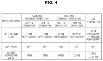
- FIG. 4 is a view illustrating operation states of an A2A valve and a second expansion valve in the refrigerant cycle illustrated in FIG. 3 .
- the A2A valve 120 may be turned off and the second expansion valve 204 of the A2A indoor unit 200 may be opened to construct the cycle such that the refrigerant flows into the A2A indoor unit 200. Accordingly, the A2A indoor unit 200 may perform the convection cooling operation through heat exchange between the refrigerant and the air in the indoor heat exchanger 202.
- the third expansion valve 304 of the A2W indoor unit 300 may be opened to construct the cycle such that the refrigerant flows into the A2W indoor unit 300. Accordingly, the A2W indoor unit 300 may perform the radiation cooling operation through heat exchange between the refrigerant and the water in the A2W heat exchanger 302.
- the second expansion valve 204 of the stationary A2A indoor unit 200 may be switched from the OPEN state to the CLOSE state. When the second expansion valve 204 is closed, flow of the refrigerant flowing in the indoor heat exchanger 202 may be prevented.
- FIG. 5 is a flowchart illustrating a control algorithm of the refrigerant cycle illustrated in FIG. 3 .
- the user operates the inputter 404 to set the operation information such as the operation mode (e.g., simultaneous cooling operation) of the air conditioning system 1, a target temperature of the indoor space, and the like.
- the operation information set by the user through the inputter 404 may be transmitted to the controller 402.
- the controller 402 may receive various kind of operation information from the inputter 404, and determine whether the A2A indoor unit 200 and the A2W indoor unit 300 are simultaneously cooling operation (500).
- the controller 402 may operate the flow path switching valve 106 to connect the first port 106a and the second port 106b of the flow path switching valve 106 and to connect the third port 106c and the fourth port 106d, and may construct the refrigerant cycle illustrated in FIG. 3 (502).
- the controller 402 may turn off the A2A valve 120 and open the second expansion valve 204 of the A2A indoor unit 200, and may thus construct the refrigerant cycle so that the refrigerant discharged from the compressor 102 flows into the A2A indoor unit 200 (504).
- the controller 402 may control the operation of the A2A valve 120 and the second expansion valve 204 to operate with a predetermined time difference in conjunction with the compressor 102 and the flow path switching valve 106.
- the refrigerant cycle in which the refrigerant sequentially circulates the compressor 102 ⁇ the flow path switching valve 106 ⁇ the outdoor heat exchanger 108 ⁇ the second expansion valve 204 of the A2A indoor unit 200 ⁇ the indoor heat exchanger 202 ⁇ the A2A valve 120 ⁇ the flow path switching valve 106 ⁇ the accumulator 104 ⁇ the compressor 102 may be constructed, resulting in implementation of the cooling operation of the A2A indoor unit 200 (506).
- the controller 402 may determine whether the condition is the operation termination condition of the A2A indoor unit 200 (508).
- the controller 402 may return to operation 506 to continue the cooling operation of the A2A indoor unit 200.
- the controller 402 may stop the cooling operation of the A2A indoor unit 200 (510).
- the controller 402 may switch the second expansion valve 204 of the A2A indoor unit 200 from the OPEN state to the CLOSE state and open the third expansion valve 304, and may thus construct the refrigerant cycle so that the refrigerant discharged from the compressor 102 flows into the A2W indoor unit 300 (512).
- the second expansion valve 204 is closed, the refrigerant discharged from the compressor 102 flows only to the A2W indoor unit 300 through the outdoor heat exchanger 108, so that the cooling performance of the A2W indoor unit 300 may be maximized.
- the controller 402 may control the operation of the A2A valve 120 and the third expansion valve 304 to operate with the predetermined time difference in conjunction with the compressor 102 and the flow path switching valve 106.
- the refrigerant cycle in which the refrigerant sequentially circulates the compressor 102 ⁇ the flow path switching valve 106 ⁇ the outdoor heat exchanger 108 ⁇ the third expansion valve 304 of the A2W indoor unit 300 ⁇ the A2W heat exchanger 302 ⁇ the flow path switching valve 106 ⁇ the accumulator 104 ⁇ the compressor 102 may be constructed, resulting in implementation of the cooling operation of the A2W indoor unit 300 (514).
- the controller 402 may determine whether the condition is the operation termination condition of the A2W indoor unit 300 (516).
- the controller 402 may return to operation 514 to continue the cooling operation of the A2W indoor unit 300.
- the controller 402 may stop the cooling operation of the A2W indoor unit 300 (518).
- FIG. 6 is a conceptual diagram illustrating a refrigerant cycle during a heating operation of an A2A indoor unit in the air conditioning system illustrated in FIG. 1 .
- the air conditioning system 1 may construct the refrigerant cycle in a single cooling operation mode of the A2A indoor unit 200.
- the controller 402 may form the refrigerant flow path in which the first port 106a is connected to the second port 106b and the third port 106c is connected to the fourth port 106d.
- the controller 402 may turn on the A2A valve 120 and open the second expansion valve 204 of the A2A indoor unit 200, and may thus control the refrigerant to flow into the A2A indoor unit 200.
- the refrigerant discharged from the compressor 102 may flow into the A2A indoor unit 200 after passing through the flow path switching valve 106 and the A2A valve 120.
- the refrigerant flowing in the A2A indoor unit 200 may flow into the outdoor heat exchanger 108 through the indoor heat exchanger 202 and the second expansion valve 204.
- the indoor heat exchanger 202 may operate as the condenser
- the outdoor heat exchanger 1082 may operate as the evaporator.
- the refrigerant flowing in the outdoor heat exchanger 108 may be suctioned into the compressor 102 after passing through the flow path switching valve 106.
- the air conditioning system 1 may construct the refrigerant cycle in which the refrigerant sequentially circulates the compressor 102 ⁇ the flow path switching valve 106 ⁇ the A2A valve 120 ⁇ the indoor heat exchanger 202 ⁇ the second expansion valve 204 of the A2A indoor unit 200 ⁇ the outdoor heat exchanger 108 ⁇ the flow path switching valve 106 ⁇ the accumulator 104 ⁇ the compressor 102, resulting in implementation of the heating operation of the A2A indoor unit 200.
- FIG. 7 is a view illustrating operation states of an A2A valve and a second expansion valve in the refrigerant cycle illustrated in FIG. 6 .
- the A2A valve 120 may be turned on and the second expansion valve 204 of the A2A indoor unit 200 may be opened to construct the cycle such that the refrigerant flows into the A2A indoor unit 200. Accordingly, the A2A indoor unit 200 may perform the convection heating operation through heat exchange between the refrigerant and the air in the indoor heat exchanger 202.
- the third expansion valve 304 of the A2W indoor unit 300 may be closed and the refrigerant does not flow into the A2W indoor unit 300. Therefore, the refrigerant discharged from the compressor 102 flows only to the A2A indoor unit 200, so that an A2A heating operation using the A2A indoor unit 200 may be performed independently.
- FIG. 8 is a flowchart illustrating a control algorithm of the refrigerant cycle illustrated in FIG. 6 .
- the user operates the inputter 404 to set the operation information such as the operation mode (e.g., single heating operation of A2A indoor unit) of the air conditioning system 1, the target temperature of the indoor space, and the like.
- the operation information set by the user through the inputter 404 may be transmitted to the controller 402.
- the controller 402 may receive various kind of operation information from the inputter 404, and determine whether the A2A indoor unit 200 is independently heating operation (600).
- the controller 402 may operate the flow path switching valve 106 to connect the first port 106a and the third port 106c of the flow path switching valve 106 and to connect the second port 106b and the fourth port 106d, and may construct the refrigerant cycle illustrated in FIG. 6 (602).
- the controller 402 may turn on the A2A valve 120, open the second expansion valve 204 of the A2A indoor unit 200 and close the third expansion valve 304 of the A2W indoor unit 300, and may thus construct the refrigerant cycle so that the refrigerant discharged from the compressor 102 flows only into the A2W indoor unit 300 (604).
- the controller 402 may provide a predetermined delay time upon turning on the A2A valve 120, so as to prevent an impact sound generated due to sudden switching of the refrigerant path.
- the refrigerant cycle in which the refrigerant sequentially circulates the compressor 102 ⁇ the flow path switching valve 106 ⁇ the A2A valve 120 ⁇ the indoor heat exchanger 202 ⁇ the second expansion valve 204 of the A2A indoor unit 200 ⁇ the outdoor heat exchanger 108 ⁇ the flow path switching valve 106 ⁇ the accumulator 104 ⁇ the compressor 102 may be constructed, resulting in implementation of the heating operation of the A2A indoor unit 200 (606).
- the controller 402 may determine whether the condition is the operation termination condition of the A2A indoor unit 200 (608).
- the controller 402 may return to operation 606 to continue the heating operation of the A2A indoor unit 200.
- the controller 402 may stop the heating operation of the A2A indoor unit 200 (610).
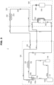
- FIG. 9 is a conceptual diagram illustrating a refrigerant cycle during a heating operation of an A2W indoor unit in the air conditioning system illustrated in FIG. 1 .
- the air conditioning system 1 may construct the refrigerant cycle in a single heating operation mode of the A2W indoor unit 300.
- the controller 402 may form the refrigerant flow path in which the first port 106a is connected to the second port 106b and the third port 106c is connected to the fourth port 106d.
- the controller 402 may turn off the A2A valve 120 and close the second expansion valve 204 of the A2A indoor unit 200, and may thus control the refrigerant to flow into the A2W indoor unit 300.
- the refrigerant discharged from the compressor 102 may flow into the A2W indoor unit 300 after passing through the flow path switching valve 106.
- the refrigerant flowing in the A2W indoor unit 300 may flow into the outdoor heat exchanger 108 through the A2W heat exchanger 302 and the third expansion valve 304.
- the refrigerant flowing in the outdoor heat exchanger 108 may be suctioned into the compressor 102 after passing through the flow path switching valve 106.
- the air conditioning system 1 may construct the refrigerant cycle in which the refrigerant sequentially circulates the compressor 102 ⁇ the flow path switching valve 106 ⁇ the A2W heat exchanger 302 ⁇ the third expansion valve 304 of the A2W indoor unit 300 ⁇ the outdoor heat exchanger 108 ⁇ the flow path switching valve 106 ⁇ the accumulator 104 ⁇ the compressor 102, resulting in implementation of the heating operation of the A2W indoor unit 300.
- the second expansion valve 204 of the A2A indoor unit 200 may be closed in conjunction with the A2A valve 120 so that the refrigerant does not generate the liquid refrigerant in the A2A indoor unit 200.
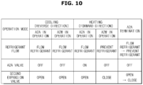
- FIG. 10 is a view illustrating operation states of an A2A valve and a second expansion valve in the refrigerant cycle illustrated in FIG. 9 .
- the A2A valve 120 may be turned off and the second expansion valve 204 of the A2A indoor unit 200 may be closed to construct the cycle such that the refrigerant flows into the A2W indoor unit 300. Accordingly, the A2W indoor unit 300 may perform the radiation heating operation through heat exchange between the refrigerant and the water in the A2W heat exchanger 302.
- the second expansion valve 204 of the A2A indoor unit 200 may be closed. Therefore, the refrigerant discharged from the compressor 102 flows to the A2W indoor unit 300, so that an A2W heating operation using the A2W indoor unit 300 may be performed independently.
- the liquid refrigerant is accumulated in the indoor heat exchanger 202 of the A2A indoor unit 200 due to the refrigerant bypass to the stationary A2A indoor unit 200.
- the heating performance of the A2W indoor unit 300 may be deteriorated.
- the A2A valve 120 may be installed in the refrigerant pipe connecting the outdoor unit 100 and the A2A indoor unit 200.
- the A2A valve 120 is turned off to prevent the refrigerant from flowing into the stationary A2A indoor unit 200, thereby preventing the liquid refrigerant from being generated in the indoor heat exchanger 202 of the A2A indoor unit 200.
- the refrigerant discharged from the compressor 102 flows into the A2W indoor unit 300 without flowing into the A2A indoor unit 200, so that the heating performance of the A2W indoor unit 300 may be prevented from deteriorating.
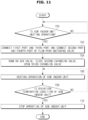
- FIG. 11 is a flowchart illustrating a control algorithm of the refrigerant cycle illustrated in FIG. 9 .
- the user operates the inputter 404 to set the operation information such as the operation mode (e.g., single heating operation of A2W indoor unit) of the air conditioning system 1, the target temperature of the indoor space, and the like.
- the operation information set by the user through the inputter 404 may be transmitted to the controller 402.
- the controller 402 may receive various kind of operation information from the inputter 404, and determine whether the A2W indoor unit 300 is independently heating operation (700).
- the controller 402 may operate the flow path switching valve 106 to connect the first port 106a and the third port 106c of the flow path switching valve 106 and to connect the second port 106b and the fourth port 106d, and may construct the refrigerant cycle illustrated in FIG. 9 (702).
- the controller 402 may turn off the A2A valve 120 and open the third expansion valve 304 of the A2W indoor unit 300, and may thus construct the refrigerant cycle so that the refrigerant flows only into the A2W indoor unit 300 (704).
- the second expansion valve 204 of the A2A indoor unit 200 is closed by interlocking with the A2A valve 120 so that flow of the refrigerant into the A2A indoor unit 200 is minimized and a pressure inside the A2A indoor unit 200 is lowered so that the impact sound is not generated.
- the controller 402 may provide a predetermined delay time upon turning off the A2A valve 120, so as to prevent the impact sound generated due to sudden switching of the refrigerant path.
- the refrigerant cycle in which the refrigerant sequentially circulates the compressor 102 ⁇ the flow path switching valve 106 ⁇ the A2W heat exchanger 302 ⁇ the third expansion valve 304 of the A2W indoor unit 300 ⁇ the outdoor heat exchanger 108 ⁇ the flow path switching valve 106 ⁇ the accumulator 104 ⁇ the compressor 102 may be constructed, resulting in implementation of the heating operation of the A2W indoor unit 300 (706).
- the controller 402 may determine whether the condition is the operation termination condition of the A2W indoor unit 300 (708).
- the controller 402 may return to operation 706 to continue the heating operation of the A2W indoor unit 300.
- the controller 402 may stop the heating operation of the A2W indoor unit 300 (710).
- the disclosure can prevent the inflow of the refrigerant into the A2A indoor unit, thereby securing the heating performance.
Landscapes
- Engineering & Computer Science (AREA)
- General Engineering & Computer Science (AREA)
- Mechanical Engineering (AREA)
- Physics & Mathematics (AREA)
- Chemical & Material Sciences (AREA)
- Combustion & Propulsion (AREA)
- Signal Processing (AREA)
- Thermal Sciences (AREA)
- Fuzzy Systems (AREA)
- Mathematical Physics (AREA)
- Life Sciences & Earth Sciences (AREA)
- Sustainable Development (AREA)
- General Physics & Mathematics (AREA)
- Automation & Control Theory (AREA)
- Human Computer Interaction (AREA)
- Air Conditioning Control Device (AREA)
- Fluid Mechanics (AREA)
Claims (13)
- Klimaanlagensystem (1), das Folgendes umfasst:eine Außeneinheit (100) mit einem Kompressor (102), einem Akkumulator (104), einem ersten Wärmetauscher (108), einem ersten Expansionsventil (110), einem Luft-zu-Luft-Ventil (A2A) und einem Strömungsweg-Umschaltventil (106);eine erste Inneneinheit (200) mit einem zweiten Wärmetauscher (202) und einem zweiten Expansionsventil (204), die konfiguriert ist, um einen Kühl-/Heizbetrieb durch Wärmeaustausch zwischen einem Kältemittel und Luft durchzuführen; undeine zweite Inneneinheit (300) mit einem dritten Wärmetauscher (302) und einem dritten Expansionsventil (304), die konfiguriert ist, um den Kühl-/Heizbetrieb durch Wärmeaustausch zwischen dem Kältemittel und Wasser durchzuführen;wobei das Strömungsweg-Umschaltventil (106) einen ersten Anschluss (106a), der mit einem Auslass (102b) des Kompressors (110) verbunden ist, einen zweiten Anschluss (106b), der mit dem ersten Wärmetauscher (108) verbunden ist, einen dritten Anschluss (106c), der mit dem zweiten Wärmetauscher (202) und dem dritten Wärmetauscher (302) verbunden ist, und einen vierten Anschluss (106d), der mit dem Akkumulator (104) der Außeneinheit (100) verbunden ist, der mit dem Kompressor (100) verbunden ist, umfasst,wobei der erste Wärmetauscher (108) mit dem zweiten Wärmetauscher (202) und dem dritten Wärmetauscher (302) verbunden ist,wobei der zweite Wärmetauscher (202) und der dritte Wärmetauscher (302) parallel geschaltet sind, undwobei das A2A-Ventil (120) in einer Kältemittelleitung zwischen dem dritten Anschluss (106c) des Strömungsweg-Umschaltventils (106) und dem zweiten Wärmetauscher (202) installiert ist und konfiguriert ist, um einen zwischen der Außeneinheit (100) und der ersten Inneneinheit (200) und der zweiten Inneneinheit (300) ausgebildeten Kältemittelkreislauf zu ändern,wobei das Klimaanlagensystem (1) weiterhin umfasst:
eine Steuerung (402), die so konfiguriert ist, dass sie das A2A-Ventil (120) steuert, um einen Strom des Kältemittels vom dritten Anschluss (106c) des Strömungsweg-Umschaltventils (106) zum zweiten Wärmetauscher (202) zu verhindern, wenn die erste Inneneinheit (200) stationär ist, und einen Heizbetrieb der zweiten Inneneinheit (300), bei dem der erste Wärmetauscher (110) als ein Verdampfer arbeitet und der dritte Wärmetauscher (302) als ein Kondensator arbeitet. - Klimaanlagensystem (1) nach Anspruch 1, wobei die Steuerung (402) konfiguriert ist, um einen Betrieb des zweiten Expansionsventils (204) und des dritten Expansionsventils (304) entsprechend dem Betriebsmodus der ersten Inneneinheit (200) und der zweiten Inneneinheit (300) zu steuern, um einen Kältemittel-Bypass zu einer der ersten Inneneinheit (200) oder der zweiten Inneneinheit (300) zu verhindern.
- Klimaanlagensystem (1) nach Anspruch 1, wobei die Steuerung (402) so konfiguriert ist, dass sie während des Heizbetriebs der zweiten Inneneinheit (300) das zweite Expansionsventil (204) in Verbindung mit dem A2A-Ventil (120) betätigt, um eine Strömung zu verhindern, dass das Kältemittel in die erste Inneneinheit (200) strömt.
- Klimaanlagensystem (1) nach Anspruch 1, wobei während eines Heizbetriebs der ersten Inneneinheit (200), bei dem der erste Wärmetauscher (110) als Verdampfer und der zweite Wärmetauscher (202) als Kondensator arbeitet, die Steuerung (402) so konfiguriert ist, dass sie das A2A-Ventil (120) einschaltet und das dritte Expansionsventil (304) schließt, um einen Kältemittelkreislauf zu bilden, in dem das Kältemittel in die erste Inneneinheit (200) strömt.
- Klimaanlagensystem (1) nach Anspruch 1, wobei die Steuerung (402) so konfiguriert ist, dass sie während eines Heizbetriebs der zweiten Inneneinheit (300) das A2A-Ventil (120) ausschaltet und das zweite Expansionsventil (204) schließt, um einen Kältemittelkreislauf zu bilden, in dem das Kältemittel in die zweite Inneneinheit (300) strömt.
- Klimaanlagensystem (1) nach Anspruch 1, wobei die Steuerung (402) so konfiguriert ist, dass sie, wenn die erste Inneneinheit (200) und die zweite Inneneinheit (300) gleichzeitig betrieben werden, das A2A-Ventil (120) ausschaltet und das zweite Expansionsventil (204) und das dritte Expansionsventil (304) öffnet, um einen Kältemittelkreislauf zu bilden, in dem das Kältemittel in die erste Inneneinheit (200) und die zweite Inneneinheit (300) strömt.
- Klimaanlagensystem (1) nach Anspruch 6, wobei die Steuerung (402) so konfiguriert ist, dass sie abwechselnd die erste Inneneinheit (200) und die zweite Inneneinheit (300) betreibt.
- Klimaanlagensystem (1) nach Anspruch 1, wobei die erste Inneneinheit (200) eine Luft-zu-Luft-(A2A)-Inneneinheit ist, die den Kühl-/Heizbetrieb in einem A2A-Modus durch Wärmeaustausch des Kältemittels mit der Luft durch den zweiten Wärmetauscher (202) durchführt.
- Klimaanlagensystem (1) nach Anspruch 1, wobei die zweite Inneneinheit (300) eine Luft-zu-Wasser-Inneneinheit (A2W) ist, die den Kühl-/Heizbetrieb in einem A2W-Modus durch Wärmeaustausch des Kältemittels mit dem Wasser über den dritten Wärmetauscher (302) durchführt.
- Verfahren zur Steuerung eines Klimaanlagensystems (1), das eine Außeneinheit (00) mit einem Kompressor (102), einem Akkumulator (104), einem ersten Wärmetauscher (108), einem ersten Expansionsventil (110), einem Luft-zu-Luft-Ventil (A2A) und einem Strömungsweg-Umschaltventil (106), eine erste Inneneinheit (200) mit einem zweiten Wärmetauscher (202) und einem zweiten Expansionsventil (204), die konfiguriert ist zum Wärmeaustausch eines Kältemittels mit Luft, und eine zweite Inneneinheit (300) mit einem dritten Wärmetauscher (302) und einem dritten Expansionsventil (304), die konfiguriert ist zum Wärmeaustausch des Kältemittels mit Wasser, umfasst, wobei das Verfahren umfasst:Bestimmen, ob sich die zweite Inneneinheit (300) in einem Heizbetrieb befindet, in dem der erste Wärmetauscher (110) als Verdampfer und der dritte Wärmetauscher (302) als Kondensator arbeitet;wenn die erste Inneneinheit (200) stationär und die zweite Inneneinheit (300) im Heizbetrieb ist, Steuern des A2A-Ventils (120), das das Strömungsweg-Umschaltventil (106) der Außeneinheit (100) und den zweiten Wärmetauscher (202) verbindet so, dass ein Strom des Kältemittels vom Strömungsweg-Umschaltventil (106) des Strömungsweg-Umschaltventils (106) zum zweiten Wärmetauscher (202) verhindert wird;Betätigen des zweiten Expansionsventils (204) in Verbindung mit dem A2A-Ventil (120), um den Strom des in die erste Inneneinheit (200) strömenden Kältemittels zu verhindern; undBetätigen des dritten Expansionsventils (304), um einen Kältemittelkreislauf zu bilden, in dem das Kältemittel in die zweite Inneneinheit (300) strömt, um den Heizbetrieb der zweiten Inneneinheit (300) durchzuführen,wobei das Strömungsweg-Umschaltventil (106) einen ersten Anschluss (106a), der mit einem Auslass (102b) des Kompressors (110) verbunden ist, einen zweiten Anschluss (106b), der mit dem ersten Wärmetauscher (108) verbunden ist, einen dritten Anschluss (106c), der mit dem zweiten Wärmetauscher (202) und dem dritten Wärmetauscher (302) verbunden ist, und einen vierten Anschluss (106d), der mit dem Akkumulator (104) der Außeneinheit (100) verbunden ist, der mit dem Kompressor (102) verbunden ist, umfasst,wobei der erste Wärmetauscher (108) mit dem zweiten Wärmetauscher (202) und dem dritten Wärmetauscher (302) verbunden ist,wobei der zweite Wärmetauscher (202) und der dritte Wärmetauscher (302) parallel geschaltet sind, undwobei das A2A-Ventil (120) in einer Kältemittelleitung zwischen dem dritten Anschluss (106c) des Strömungsweg-Umschaltventils (106) und dem zweiten Wärmetauscher (202) installiert ist und konfiguriert ist, um einen zwischen der Außeneinheit (100) und der ersten Inneneinheit (200) und der zweiten Inneneinheit (300) ausgebildeten Kältemittelkreislauf zu ändern.
- Verfahren nach Anspruch 10, das ferner Folgendes umfasstBestimmen, ob sich die erste Inneneinheit (200) im Heizbetrieb befindet, bei dem der erste Wärmetauscher (110) als Verdampfer und der zweite Wärmetauscher (202) als Kondensator arbeitet;wenn die erste Inneneinheit (200) im Heizbetrieb ist, Steuern des A2A-Ventils (120), um die Außeneinheit (100) und die erste Inneneinheit (200) zu verbinden; undBetätigen des zweiten Expansionsventils (204), um den Kältemittelkreislauf zu bilden, in dem das Kältemittel in die erste Inneneinheit (200) strömt, um den Heizbetrieb der ersten Inneneinheit (200) durchzuführen.
- Verfahren nach Anspruch 10, das ferner umfasst:
Steuern des zweiten Expansionsventils (204) und des dritten Expansionsventils (304) entsprechend einem Betriebsmodus der ersten Inneneinheit (200) und der zweiten Inneneinheit (300), um den Kältemittel-Bypass zu einer der ersten Inneneinheit (200) oder der zweiten Inneneinheit (300) zu verhindern. - Verfahren nach Anspruch 10, das ferner umfasst:Bestimmen, ob die erste Inneneinheit (200) und die zweite Inneneinheit (300) gleichzeitig betrieben werden; undwenn die erste Inneneinheit (200) und die zweite Inneneinheit (300) gleichzeitig betrieben werden, abwechselndes Öffnen des zweiten Expansionsventils (204) und des dritten Expansionsventils (304), um den Kältemittelkreislauf zu bilden, in dem das Kältemittel in die erste Inneneinheit (200) und die zweite Inneneinheit (300) strömt.
Applications Claiming Priority (2)
| Application Number | Priority Date | Filing Date | Title |
|---|---|---|---|
| KR1020170053028A KR102353913B1 (ko) | 2017-04-25 | 2017-04-25 | 공기 조화 시스템 및 그 제어 방법 |
| PCT/KR2018/003269 WO2018199474A1 (ko) | 2017-04-25 | 2018-03-21 | 공기 조화 시스템 및 그 제어 방법 |
Publications (3)
| Publication Number | Publication Date |
|---|---|
| EP3598015A1 EP3598015A1 (de) | 2020-01-22 |
| EP3598015A4 EP3598015A4 (de) | 2020-04-01 |
| EP3598015B1 true EP3598015B1 (de) | 2024-03-06 |
Family
ID=63918581
Family Applications (1)
| Application Number | Title | Priority Date | Filing Date |
|---|---|---|---|
| EP18790680.5A Active EP3598015B1 (de) | 2017-04-25 | 2018-03-21 | Klimaanlagensystem und steuerungsverfahren dafür |
Country Status (4)
| Country | Link |
|---|---|
| US (1) | US11371735B2 (de) |
| EP (1) | EP3598015B1 (de) |
| KR (1) | KR102353913B1 (de) |
| WO (1) | WO2018199474A1 (de) |
Families Citing this family (5)
| Publication number | Priority date | Publication date | Assignee | Title |
|---|---|---|---|---|
| KR102261131B1 (ko) * | 2019-12-18 | 2021-06-03 | 이재옥 | 제상과 바닥 및 공간의 냉,난방기능을 갖는 히트펌프 공기조화기 |
| EP4083536A1 (de) * | 2021-04-26 | 2022-11-02 | Electrolux Appliances Aktiebolag | Verbesserte steuerung eines kühlsystems |
| CN115468326A (zh) * | 2021-06-10 | 2022-12-13 | 华为数字能源技术有限公司 | 复合制冷系统和数据中心 |
| KR20230134730A (ko) * | 2022-03-15 | 2023-09-22 | 삼성전자주식회사 | 히트 펌프 시스템 및 그 제어 방법 |
| KR102575786B1 (ko) * | 2022-11-10 | 2023-09-08 | 대성히트에너시스 주식회사 | 다중 부하를 갖는 지열히트펌프 장치 |
Citations (1)
| Publication number | Priority date | Publication date | Assignee | Title |
|---|---|---|---|---|
| EP2728280A1 (de) * | 2012-11-02 | 2014-05-07 | LG Electronics, Inc. | Klimaanlage und Steuerverfahren dafür |
Family Cites Families (24)
| Publication number | Priority date | Publication date | Assignee | Title |
|---|---|---|---|---|
| GB2215867B (en) * | 1988-02-09 | 1992-09-02 | Toshiba Kk | Air conditioner system with control for optimum refrigerant temperature |
| US5493871A (en) * | 1991-11-12 | 1996-02-27 | Eiermann; Kenneth L. | Method and apparatus for latent heat extraction |
| US5802862A (en) * | 1991-11-12 | 1998-09-08 | Eiermann; Kenneth L. | Method and apparatus for latent heat extraction with cooling coil freeze protection and complete recovery of heat of rejection in Dx systems |
| JP3211405B2 (ja) * | 1992-10-01 | 2001-09-25 | 株式会社日立製作所 | 冷媒組成検出装置 |
| JP3060770B2 (ja) * | 1993-02-26 | 2000-07-10 | ダイキン工業株式会社 | 冷凍装置 |
| JP3289366B2 (ja) * | 1993-03-08 | 2002-06-04 | ダイキン工業株式会社 | 冷凍装置 |
| JPH07234038A (ja) * | 1994-02-18 | 1995-09-05 | Sanyo Electric Co Ltd | 多室型冷暖房装置及びその運転方法 |
| KR0132997B1 (ko) * | 1994-08-20 | 1998-04-21 | 김광호 | 공기조화기의 실외기 |
| US5664421A (en) * | 1995-04-12 | 1997-09-09 | Sanyo Electric Co., Ltd. | Heat pump type air conditioner using circulating fluid branching passage |
| JPH10197171A (ja) * | 1996-12-27 | 1998-07-31 | Daikin Ind Ltd | 冷凍装置及びその製造方法 |
| KR100274257B1 (ko) * | 1998-04-06 | 2001-03-02 | 윤종용 | 냉매량 조절을 위한 바이패스 부를 가지는 멀티 에어컨 |
| JP3969381B2 (ja) | 2003-11-12 | 2007-09-05 | 松下電器産業株式会社 | 多室型空気調和機 |
| KR100792518B1 (ko) | 2006-10-23 | 2008-01-10 | 삼성전자주식회사 | 멀티 에어컨의 그룹설정방법 |
| KR20110099558A (ko) * | 2010-03-02 | 2011-09-08 | 삼성전자주식회사 | 히트 펌프 시스템 및 그 제어방법 |
| KR101507454B1 (ko) | 2011-06-23 | 2015-03-31 | 삼성전자 주식회사 | 히트펌프 및 그 제어 방법 |
| CN103842747B (zh) | 2011-10-04 | 2016-02-24 | 三菱电机株式会社 | 制冷循环装置 |
| KR101328761B1 (ko) | 2011-10-25 | 2013-11-13 | 엘지전자 주식회사 | 공기 조화기 |
| EP2610559A2 (de) * | 2012-01-02 | 2013-07-03 | Samsung Electronics Co., Ltd | Wärmepumpe und Steuerungsverfahren dafür |
| KR20130079990A (ko) * | 2012-01-02 | 2013-07-11 | 삼성전자주식회사 | 히트 펌프 및 그 제어 방법 |
| KR102025740B1 (ko) * | 2012-10-29 | 2019-09-26 | 삼성전자주식회사 | 히트펌프장치 |
| KR101988034B1 (ko) * | 2012-11-19 | 2019-06-11 | 엘지전자 주식회사 | 공기조화기 |
| JP5794279B2 (ja) | 2013-11-14 | 2015-10-14 | ダイキン工業株式会社 | 空気調和機 |
| WO2016081933A1 (en) * | 2014-11-21 | 2016-05-26 | 7Ac Technologies, Inc. | Methods and systems for mini-split liquid desiccant air conditioning |
| JP6687116B2 (ja) * | 2016-08-25 | 2020-04-22 | 三菱電機株式会社 | ヒートポンプ装置 |
-
2017
- 2017-04-25 KR KR1020170053028A patent/KR102353913B1/ko active Active
-
2018
- 2018-03-21 WO PCT/KR2018/003269 patent/WO2018199474A1/ko not_active Ceased
- 2018-03-21 EP EP18790680.5A patent/EP3598015B1/de active Active
- 2018-03-21 US US16/608,805 patent/US11371735B2/en active Active
Patent Citations (1)
| Publication number | Priority date | Publication date | Assignee | Title |
|---|---|---|---|---|
| EP2728280A1 (de) * | 2012-11-02 | 2014-05-07 | LG Electronics, Inc. | Klimaanlage und Steuerverfahren dafür |
Also Published As
| Publication number | Publication date |
|---|---|
| KR20180119360A (ko) | 2018-11-02 |
| WO2018199474A1 (ko) | 2018-11-01 |
| EP3598015A4 (de) | 2020-04-01 |
| KR102353913B1 (ko) | 2022-01-21 |
| US11371735B2 (en) | 2022-06-28 |
| EP3598015A1 (de) | 2020-01-22 |
| US20200191423A1 (en) | 2020-06-18 |
Similar Documents
| Publication | Publication Date | Title |
|---|---|---|
| US11371735B2 (en) | Air conditioning system and method of controlling the same | |
| US12578124B2 (en) | Integrated demand water heating using a capacity modulated heat pump with desuperheater | |
| US11506430B2 (en) | Air conditioning system with capacity control and controlled hot water generation | |
| EP2397782B1 (de) | Mit einer Wärmepumpe assoziierte Heißwasserversorgungsvorrichtung | |
| US9593872B2 (en) | Heat pump | |
| JP6081033B1 (ja) | 空気調和装置 | |
| EP2615392B1 (de) | Kaskadenwärmepumpe | |
| EP2725310B1 (de) | Wärmepumpenvorrichtung | |
| US20130167559A1 (en) | Heat pump and control method thereof | |
| EP3631325B1 (de) | Klimaanlage und verfahren zur steuerung davon | |
| EP2375188B1 (de) | Klimaanlage | |
| US20150292777A1 (en) | Air-conditioning apparatus | |
| US9733001B2 (en) | Multi type air conditioner and cooling and heating control method thereof | |
| EP2669598B1 (de) | Klimaanlage | |
| EP2354723A2 (de) | Kühlsystem | |
| US20170108250A1 (en) | Air conditioner | |
| GB2566381A (en) | Refrigeration cycle system | |
| KR102688990B1 (ko) | 공기조화장치 및 그 제어방법 | |
| WO2012121326A1 (ja) | 2元冷凍サイクル装置 | |
| US20250224152A1 (en) | Refrigeration cycle apparatus | |
| EP2093508B1 (de) | Klimaanlage und Steuerverfahren dafür | |
| KR102080836B1 (ko) | 공기조화 시스템 | |
| EP3112777B1 (de) | Klimaanlage und betriebsverfahren dafür | |
| KR101146409B1 (ko) | 냉매시스템 | |
| WO2023158583A1 (en) | Heat pump systems with boost heat pump |
Legal Events
| Date | Code | Title | Description |
|---|---|---|---|
| STAA | Information on the status of an ep patent application or granted ep patent |
Free format text: STATUS: THE INTERNATIONAL PUBLICATION HAS BEEN MADE |
|
| PUAI | Public reference made under article 153(3) epc to a published international application that has entered the european phase |
Free format text: ORIGINAL CODE: 0009012 |
|
| STAA | Information on the status of an ep patent application or granted ep patent |
Free format text: STATUS: REQUEST FOR EXAMINATION WAS MADE |
|
| 17P | Request for examination filed |
Effective date: 20191017 |
|
| AK | Designated contracting states |
Kind code of ref document: A1 Designated state(s): AL AT BE BG CH CY CZ DE DK EE ES FI FR GB GR HR HU IE IS IT LI LT LU LV MC MK MT NL NO PL PT RO RS SE SI SK SM TR |
|
| AX | Request for extension of the european patent |
Extension state: BA ME |
|
| A4 | Supplementary search report drawn up and despatched |
Effective date: 20200228 |
|
| RIC1 | Information provided on ipc code assigned before grant |
Ipc: F25B 41/04 20060101ALI20200224BHEP Ipc: F24F 11/65 20180101ALI20200224BHEP Ipc: F24F 11/84 20180101ALI20200224BHEP Ipc: F24F 1/00 20190101ALI20200224BHEP Ipc: F24F 11/83 20180101AFI20200224BHEP Ipc: F25B 49/02 20060101ALI20200224BHEP Ipc: F25B 13/00 20060101ALI20200224BHEP Ipc: F24F 11/30 20180101ALI20200224BHEP Ipc: F24F 5/00 20060101ALI20200224BHEP |
|
| DAV | Request for validation of the european patent (deleted) | ||
| DAX | Request for extension of the european patent (deleted) | ||
| STAA | Information on the status of an ep patent application or granted ep patent |
Free format text: STATUS: EXAMINATION IS IN PROGRESS |
|
| 17Q | First examination report despatched |
Effective date: 20211215 |
|
| REG | Reference to a national code |
Ref country code: DE Ref legal event code: R079 Free format text: PREVIOUS MAIN CLASS: F24F0011830000 Ipc: F25B0041200000 Ref country code: DE Ref legal event code: R079 Ref document number: 602018066276 Country of ref document: DE Free format text: PREVIOUS MAIN CLASS: F24F0011830000 Ipc: F25B0041200000 |
|
| GRAP | Despatch of communication of intention to grant a patent |
Free format text: ORIGINAL CODE: EPIDOSNIGR1 |
|
| STAA | Information on the status of an ep patent application or granted ep patent |
Free format text: STATUS: GRANT OF PATENT IS INTENDED |
|
| RIC1 | Information provided on ipc code assigned before grant |
Ipc: F25B 41/20 20210101AFI20230925BHEP |
|
| INTG | Intention to grant announced |
Effective date: 20231011 |
|
| GRAS | Grant fee paid |
Free format text: ORIGINAL CODE: EPIDOSNIGR3 |
|
| GRAA | (expected) grant |
Free format text: ORIGINAL CODE: 0009210 |
|
| STAA | Information on the status of an ep patent application or granted ep patent |
Free format text: STATUS: THE PATENT HAS BEEN GRANTED |
|
| AK | Designated contracting states |
Kind code of ref document: B1 Designated state(s): AL AT BE BG CH CY CZ DE DK EE ES FI FR GB GR HR HU IE IS IT LI LT LU LV MC MK MT NL NO PL PT RO RS SE SI SK SM TR |
|
| REG | Reference to a national code |
Ref country code: GB Ref legal event code: FG4D |
|
| REG | Reference to a national code |
Ref country code: CH Ref legal event code: EP |
|
| REG | Reference to a national code |
Ref country code: DE Ref legal event code: R096 Ref document number: 602018066276 Country of ref document: DE |
|
| REG | Reference to a national code |
Ref country code: IE Ref legal event code: FG4D |
|
| REG | Reference to a national code |
Ref country code: LT Ref legal event code: MG9D |
|
| PG25 | Lapsed in a contracting state [announced via postgrant information from national office to epo] |
Ref country code: LT Free format text: LAPSE BECAUSE OF FAILURE TO SUBMIT A TRANSLATION OF THE DESCRIPTION OR TO PAY THE FEE WITHIN THE PRESCRIBED TIME-LIMIT Effective date: 20240306 |
|
| REG | Reference to a national code |
Ref country code: NL Ref legal event code: MP Effective date: 20240306 |
|
| PG25 | Lapsed in a contracting state [announced via postgrant information from national office to epo] |
Ref country code: GR Free format text: LAPSE BECAUSE OF FAILURE TO SUBMIT A TRANSLATION OF THE DESCRIPTION OR TO PAY THE FEE WITHIN THE PRESCRIBED TIME-LIMIT Effective date: 20240607 |
|
| PG25 | Lapsed in a contracting state [announced via postgrant information from national office to epo] |
Ref country code: RS Free format text: LAPSE BECAUSE OF FAILURE TO SUBMIT A TRANSLATION OF THE DESCRIPTION OR TO PAY THE FEE WITHIN THE PRESCRIBED TIME-LIMIT Effective date: 20240606 Ref country code: HR Free format text: LAPSE BECAUSE OF FAILURE TO SUBMIT A TRANSLATION OF THE DESCRIPTION OR TO PAY THE FEE WITHIN THE PRESCRIBED TIME-LIMIT Effective date: 20240306 |
|
| PG25 | Lapsed in a contracting state [announced via postgrant information from national office to epo] |
Ref country code: ES Free format text: LAPSE BECAUSE OF FAILURE TO SUBMIT A TRANSLATION OF THE DESCRIPTION OR TO PAY THE FEE WITHIN THE PRESCRIBED TIME-LIMIT Effective date: 20240306 |
|
| PG25 | Lapsed in a contracting state [announced via postgrant information from national office to epo] |
Ref country code: RS Free format text: LAPSE BECAUSE OF FAILURE TO SUBMIT A TRANSLATION OF THE DESCRIPTION OR TO PAY THE FEE WITHIN THE PRESCRIBED TIME-LIMIT Effective date: 20240606 Ref country code: NO Free format text: LAPSE BECAUSE OF FAILURE TO SUBMIT A TRANSLATION OF THE DESCRIPTION OR TO PAY THE FEE WITHIN THE PRESCRIBED TIME-LIMIT Effective date: 20240606 Ref country code: LT Free format text: LAPSE BECAUSE OF FAILURE TO SUBMIT A TRANSLATION OF THE DESCRIPTION OR TO PAY THE FEE WITHIN THE PRESCRIBED TIME-LIMIT Effective date: 20240306 Ref country code: HR Free format text: LAPSE BECAUSE OF FAILURE TO SUBMIT A TRANSLATION OF THE DESCRIPTION OR TO PAY THE FEE WITHIN THE PRESCRIBED TIME-LIMIT Effective date: 20240306 Ref country code: GR Free format text: LAPSE BECAUSE OF FAILURE TO SUBMIT A TRANSLATION OF THE DESCRIPTION OR TO PAY THE FEE WITHIN THE PRESCRIBED TIME-LIMIT Effective date: 20240607 Ref country code: FI Free format text: LAPSE BECAUSE OF FAILURE TO SUBMIT A TRANSLATION OF THE DESCRIPTION OR TO PAY THE FEE WITHIN THE PRESCRIBED TIME-LIMIT Effective date: 20240306 Ref country code: ES Free format text: LAPSE BECAUSE OF FAILURE TO SUBMIT A TRANSLATION OF THE DESCRIPTION OR TO PAY THE FEE WITHIN THE PRESCRIBED TIME-LIMIT Effective date: 20240306 Ref country code: BG Free format text: LAPSE BECAUSE OF FAILURE TO SUBMIT A TRANSLATION OF THE DESCRIPTION OR TO PAY THE FEE WITHIN THE PRESCRIBED TIME-LIMIT Effective date: 20240306 |
|
| REG | Reference to a national code |
Ref country code: AT Ref legal event code: MK05 Ref document number: 1663890 Country of ref document: AT Kind code of ref document: T Effective date: 20240306 |
|
| PG25 | Lapsed in a contracting state [announced via postgrant information from national office to epo] |
Ref country code: SE Free format text: LAPSE BECAUSE OF FAILURE TO SUBMIT A TRANSLATION OF THE DESCRIPTION OR TO PAY THE FEE WITHIN THE PRESCRIBED TIME-LIMIT Effective date: 20240306 Ref country code: LV Free format text: LAPSE BECAUSE OF FAILURE TO SUBMIT A TRANSLATION OF THE DESCRIPTION OR TO PAY THE FEE WITHIN THE PRESCRIBED TIME-LIMIT Effective date: 20240306 |
|
| PG25 | Lapsed in a contracting state [announced via postgrant information from national office to epo] |
Ref country code: NL Free format text: LAPSE BECAUSE OF FAILURE TO SUBMIT A TRANSLATION OF THE DESCRIPTION OR TO PAY THE FEE WITHIN THE PRESCRIBED TIME-LIMIT Effective date: 20240306 |
|
| PG25 | Lapsed in a contracting state [announced via postgrant information from national office to epo] |
Ref country code: NL Free format text: LAPSE BECAUSE OF FAILURE TO SUBMIT A TRANSLATION OF THE DESCRIPTION OR TO PAY THE FEE WITHIN THE PRESCRIBED TIME-LIMIT Effective date: 20240306 |
|
| PG25 | Lapsed in a contracting state [announced via postgrant information from national office to epo] |
Ref country code: IS Free format text: LAPSE BECAUSE OF FAILURE TO SUBMIT A TRANSLATION OF THE DESCRIPTION OR TO PAY THE FEE WITHIN THE PRESCRIBED TIME-LIMIT Effective date: 20240706 |
|
| PG25 | Lapsed in a contracting state [announced via postgrant information from national office to epo] |
Ref country code: PT Free format text: LAPSE BECAUSE OF FAILURE TO SUBMIT A TRANSLATION OF THE DESCRIPTION OR TO PAY THE FEE WITHIN THE PRESCRIBED TIME-LIMIT Effective date: 20240708 Ref country code: SM Free format text: LAPSE BECAUSE OF FAILURE TO SUBMIT A TRANSLATION OF THE DESCRIPTION OR TO PAY THE FEE WITHIN THE PRESCRIBED TIME-LIMIT Effective date: 20240306 |
|
| PG25 | Lapsed in a contracting state [announced via postgrant information from national office to epo] |
Ref country code: CZ Free format text: LAPSE BECAUSE OF FAILURE TO SUBMIT A TRANSLATION OF THE DESCRIPTION OR TO PAY THE FEE WITHIN THE PRESCRIBED TIME-LIMIT Effective date: 20240306 Ref country code: EE Free format text: LAPSE BECAUSE OF FAILURE TO SUBMIT A TRANSLATION OF THE DESCRIPTION OR TO PAY THE FEE WITHIN THE PRESCRIBED TIME-LIMIT Effective date: 20240306 |
|
| PG25 | Lapsed in a contracting state [announced via postgrant information from national office to epo] |
Ref country code: AT Free format text: LAPSE BECAUSE OF FAILURE TO SUBMIT A TRANSLATION OF THE DESCRIPTION OR TO PAY THE FEE WITHIN THE PRESCRIBED TIME-LIMIT Effective date: 20240306 |
|
| PG25 | Lapsed in a contracting state [announced via postgrant information from national office to epo] |
Ref country code: PL Free format text: LAPSE BECAUSE OF FAILURE TO SUBMIT A TRANSLATION OF THE DESCRIPTION OR TO PAY THE FEE WITHIN THE PRESCRIBED TIME-LIMIT Effective date: 20240306 |
|
| PG25 | Lapsed in a contracting state [announced via postgrant information from national office to epo] |
Ref country code: SK Free format text: LAPSE BECAUSE OF FAILURE TO SUBMIT A TRANSLATION OF THE DESCRIPTION OR TO PAY THE FEE WITHIN THE PRESCRIBED TIME-LIMIT Effective date: 20240306 |
|
| PG25 | Lapsed in a contracting state [announced via postgrant information from national office to epo] |
Ref country code: SM Free format text: LAPSE BECAUSE OF FAILURE TO SUBMIT A TRANSLATION OF THE DESCRIPTION OR TO PAY THE FEE WITHIN THE PRESCRIBED TIME-LIMIT Effective date: 20240306 Ref country code: SK Free format text: LAPSE BECAUSE OF FAILURE TO SUBMIT A TRANSLATION OF THE DESCRIPTION OR TO PAY THE FEE WITHIN THE PRESCRIBED TIME-LIMIT Effective date: 20240306 Ref country code: RO Free format text: LAPSE BECAUSE OF FAILURE TO SUBMIT A TRANSLATION OF THE DESCRIPTION OR TO PAY THE FEE WITHIN THE PRESCRIBED TIME-LIMIT Effective date: 20240306 Ref country code: PT Free format text: LAPSE BECAUSE OF FAILURE TO SUBMIT A TRANSLATION OF THE DESCRIPTION OR TO PAY THE FEE WITHIN THE PRESCRIBED TIME-LIMIT Effective date: 20240708 Ref country code: PL Free format text: LAPSE BECAUSE OF FAILURE TO SUBMIT A TRANSLATION OF THE DESCRIPTION OR TO PAY THE FEE WITHIN THE PRESCRIBED TIME-LIMIT Effective date: 20240306 Ref country code: IS Free format text: LAPSE BECAUSE OF FAILURE TO SUBMIT A TRANSLATION OF THE DESCRIPTION OR TO PAY THE FEE WITHIN THE PRESCRIBED TIME-LIMIT Effective date: 20240706 Ref country code: EE Free format text: LAPSE BECAUSE OF FAILURE TO SUBMIT A TRANSLATION OF THE DESCRIPTION OR TO PAY THE FEE WITHIN THE PRESCRIBED TIME-LIMIT Effective date: 20240306 Ref country code: CZ Free format text: LAPSE BECAUSE OF FAILURE TO SUBMIT A TRANSLATION OF THE DESCRIPTION OR TO PAY THE FEE WITHIN THE PRESCRIBED TIME-LIMIT Effective date: 20240306 Ref country code: AT Free format text: LAPSE BECAUSE OF FAILURE TO SUBMIT A TRANSLATION OF THE DESCRIPTION OR TO PAY THE FEE WITHIN THE PRESCRIBED TIME-LIMIT Effective date: 20240306 |
|
| REG | Reference to a national code |
Ref country code: CH Ref legal event code: PL |
|
| PG25 | Lapsed in a contracting state [announced via postgrant information from national office to epo] |
Ref country code: LU Free format text: LAPSE BECAUSE OF NON-PAYMENT OF DUE FEES Effective date: 20240321 |
|
| PG25 | Lapsed in a contracting state [announced via postgrant information from national office to epo] |
Ref country code: LU Free format text: LAPSE BECAUSE OF NON-PAYMENT OF DUE FEES Effective date: 20240321 |
|
| PG25 | Lapsed in a contracting state [announced via postgrant information from national office to epo] |
Ref country code: IT Free format text: LAPSE BECAUSE OF FAILURE TO SUBMIT A TRANSLATION OF THE DESCRIPTION OR TO PAY THE FEE WITHIN THE PRESCRIBED TIME-LIMIT Effective date: 20240306 |
|
| REG | Reference to a national code |
Ref country code: DE Ref legal event code: R097 Ref document number: 602018066276 Country of ref document: DE |
|
| REG | Reference to a national code |
Ref country code: BE Ref legal event code: MM Effective date: 20240331 |
|
| PG25 | Lapsed in a contracting state [announced via postgrant information from national office to epo] |
Ref country code: IT Free format text: LAPSE BECAUSE OF FAILURE TO SUBMIT A TRANSLATION OF THE DESCRIPTION OR TO PAY THE FEE WITHIN THE PRESCRIBED TIME-LIMIT Effective date: 20240306 |
|
| PG25 | Lapsed in a contracting state [announced via postgrant information from national office to epo] |
Ref country code: MC Free format text: LAPSE BECAUSE OF FAILURE TO SUBMIT A TRANSLATION OF THE DESCRIPTION OR TO PAY THE FEE WITHIN THE PRESCRIBED TIME-LIMIT Effective date: 20240306 |
|
| PLBE | No opposition filed within time limit |
Free format text: ORIGINAL CODE: 0009261 |
|
| STAA | Information on the status of an ep patent application or granted ep patent |
Free format text: STATUS: NO OPPOSITION FILED WITHIN TIME LIMIT |
|
| PG25 | Lapsed in a contracting state [announced via postgrant information from national office to epo] |
Ref country code: DK Free format text: LAPSE BECAUSE OF FAILURE TO SUBMIT A TRANSLATION OF THE DESCRIPTION OR TO PAY THE FEE WITHIN THE PRESCRIBED TIME-LIMIT Effective date: 20240306 |
|
| PG25 | Lapsed in a contracting state [announced via postgrant information from national office to epo] |
Ref country code: BE Free format text: LAPSE BECAUSE OF NON-PAYMENT OF DUE FEES Effective date: 20240331 |
|
| PG25 | Lapsed in a contracting state [announced via postgrant information from national office to epo] |
Ref country code: IE Free format text: LAPSE BECAUSE OF NON-PAYMENT OF DUE FEES Effective date: 20240321 |
|
| PG25 | Lapsed in a contracting state [announced via postgrant information from national office to epo] |
Ref country code: MC Free format text: LAPSE BECAUSE OF FAILURE TO SUBMIT A TRANSLATION OF THE DESCRIPTION OR TO PAY THE FEE WITHIN THE PRESCRIBED TIME-LIMIT Effective date: 20240306 Ref country code: IE Free format text: LAPSE BECAUSE OF NON-PAYMENT OF DUE FEES Effective date: 20240321 Ref country code: DK Free format text: LAPSE BECAUSE OF FAILURE TO SUBMIT A TRANSLATION OF THE DESCRIPTION OR TO PAY THE FEE WITHIN THE PRESCRIBED TIME-LIMIT Effective date: 20240306 Ref country code: BE Free format text: LAPSE BECAUSE OF NON-PAYMENT OF DUE FEES Effective date: 20240331 Ref country code: CH Free format text: LAPSE BECAUSE OF NON-PAYMENT OF DUE FEES Effective date: 20240331 |
|
| 26N | No opposition filed |
Effective date: 20241209 |
|
| GBPC | Gb: european patent ceased through non-payment of renewal fee |
Effective date: 20240606 |
|
| PG25 | Lapsed in a contracting state [announced via postgrant information from national office to epo] |
Ref country code: SI Free format text: LAPSE BECAUSE OF FAILURE TO SUBMIT A TRANSLATION OF THE DESCRIPTION OR TO PAY THE FEE WITHIN THE PRESCRIBED TIME-LIMIT Effective date: 20240306 |
|
| PG25 | Lapsed in a contracting state [announced via postgrant information from national office to epo] |
Ref country code: FR Free format text: LAPSE BECAUSE OF NON-PAYMENT OF DUE FEES Effective date: 20240506 |
|
| PG25 | Lapsed in a contracting state [announced via postgrant information from national office to epo] |
Ref country code: GB Free format text: LAPSE BECAUSE OF NON-PAYMENT OF DUE FEES Effective date: 20240606 |
|
| PG25 | Lapsed in a contracting state [announced via postgrant information from national office to epo] |
Ref country code: CY Free format text: LAPSE BECAUSE OF FAILURE TO SUBMIT A TRANSLATION OF THE DESCRIPTION OR TO PAY THE FEE WITHIN THE PRESCRIBED TIME-LIMIT; INVALID AB INITIO Effective date: 20180321 |
|
| PG25 | Lapsed in a contracting state [announced via postgrant information from national office to epo] |
Ref country code: HU Free format text: LAPSE BECAUSE OF FAILURE TO SUBMIT A TRANSLATION OF THE DESCRIPTION OR TO PAY THE FEE WITHIN THE PRESCRIBED TIME-LIMIT; INVALID AB INITIO Effective date: 20180321 |
|
| PG25 | Lapsed in a contracting state [announced via postgrant information from national office to epo] |
Ref country code: TR Free format text: LAPSE BECAUSE OF FAILURE TO SUBMIT A TRANSLATION OF THE DESCRIPTION OR TO PAY THE FEE WITHIN THE PRESCRIBED TIME-LIMIT Effective date: 20240306 |
|
| PGFP | Annual fee paid to national office [announced via postgrant information from national office to epo] |
Ref country code: DE Payment date: 20260220 Year of fee payment: 9 |