EP3631288B1 - Led-lichtmodul für einen kraftfahrzeugscheinwerfer - Google Patents
Led-lichtmodul für einen kraftfahrzeugscheinwerfer Download PDFInfo
- Publication number
- EP3631288B1 EP3631288B1 EP18726755.4A EP18726755A EP3631288B1 EP 3631288 B1 EP3631288 B1 EP 3631288B1 EP 18726755 A EP18726755 A EP 18726755A EP 3631288 B1 EP3631288 B1 EP 3631288B1
- Authority
- EP
- European Patent Office
- Prior art keywords
- led
- light
- light module
- reflector assembly
- led light
- Prior art date
- Legal status (The legal status is an assumption and is not a legal conclusion. Google has not performed a legal analysis and makes no representation as to the accuracy of the status listed.)
- Active
Links
- 230000005540 biological transmission Effects 0.000 description 8
- 229910052782 aluminium Inorganic materials 0.000 description 3
- XAGFODPZIPBFFR-UHFFFAOYSA-N aluminium Chemical compound [Al] XAGFODPZIPBFFR-UHFFFAOYSA-N 0.000 description 3
- 239000000463 material Substances 0.000 description 3
- 229910052751 metal Inorganic materials 0.000 description 2
- 239000002184 metal Substances 0.000 description 2
- ORQBXQOJMQIAOY-UHFFFAOYSA-N nobelium Chemical compound [No] ORQBXQOJMQIAOY-UHFFFAOYSA-N 0.000 description 2
- 238000010276 construction Methods 0.000 description 1
- 230000003993 interaction Effects 0.000 description 1
Images


Classifications
-
- F—MECHANICAL ENGINEERING; LIGHTING; HEATING; WEAPONS; BLASTING
- F21—LIGHTING
- F21S—NON-PORTABLE LIGHTING DEVICES; SYSTEMS THEREOF; VEHICLE LIGHTING DEVICES SPECIALLY ADAPTED FOR VEHICLE EXTERIORS
- F21S41/00—Illuminating devices specially adapted for vehicle exteriors, e.g. headlamps
- F21S41/10—Illuminating devices specially adapted for vehicle exteriors, e.g. headlamps characterised by the light source
- F21S41/14—Illuminating devices specially adapted for vehicle exteriors, e.g. headlamps characterised by the light source characterised by the type of light source
- F21S41/141—Light emitting diodes [LED]
- F21S41/147—Light emitting diodes [LED] the main emission direction of the LED being angled to the optical axis of the illuminating device
- F21S41/148—Light emitting diodes [LED] the main emission direction of the LED being angled to the optical axis of the illuminating device the main emission direction of the LED being perpendicular to the optical axis
-
- F—MECHANICAL ENGINEERING; LIGHTING; HEATING; WEAPONS; BLASTING
- F21—LIGHTING
- F21S—NON-PORTABLE LIGHTING DEVICES; SYSTEMS THEREOF; VEHICLE LIGHTING DEVICES SPECIALLY ADAPTED FOR VEHICLE EXTERIORS
- F21S41/00—Illuminating devices specially adapted for vehicle exteriors, e.g. headlamps
- F21S41/30—Illuminating devices specially adapted for vehicle exteriors, e.g. headlamps characterised by reflectors
- F21S41/39—Attachment thereof
-
- F—MECHANICAL ENGINEERING; LIGHTING; HEATING; WEAPONS; BLASTING
- F21—LIGHTING
- F21S—NON-PORTABLE LIGHTING DEVICES; SYSTEMS THEREOF; VEHICLE LIGHTING DEVICES SPECIALLY ADAPTED FOR VEHICLE EXTERIORS
- F21S41/00—Illuminating devices specially adapted for vehicle exteriors, e.g. headlamps
- F21S41/60—Illuminating devices specially adapted for vehicle exteriors, e.g. headlamps characterised by a variable light distribution
- F21S41/67—Illuminating devices specially adapted for vehicle exteriors, e.g. headlamps characterised by a variable light distribution by acting on reflectors
- F21S41/675—Illuminating devices specially adapted for vehicle exteriors, e.g. headlamps characterised by a variable light distribution by acting on reflectors by moving reflectors
-
- B—PERFORMING OPERATIONS; TRANSPORTING
- B60—VEHICLES IN GENERAL
- B60Q—ARRANGEMENT OF SIGNALLING OR LIGHTING DEVICES, THE MOUNTING OR SUPPORTING THEREOF OR CIRCUITS THEREFOR, FOR VEHICLES IN GENERAL
- B60Q2200/00—Special features or arrangements of vehicle headlamps
- B60Q2200/30—Special arrangements for adjusting headlamps, e.g. means for transmitting the movements for adjusting the lamps
Definitions
- the present invention relates to an LED light module for a motor vehicle headlight.
- the light module comprises at least one LED for emitting light, a reflector assembly rotatably mounted in a holding frame by means of at least one bearing point about a vertical axis of rotation with a reflector for reflecting at least part of the emitted light, an electric drive unit for rotating the reflector assembly around the vertical axis of rotation, and an electrical control unit for controlling the drive unit.
- each LED light module can be rotated about a vertical axis of rotation in a horizontal direction in order to implement a cornering light function. All LED light modules the light module assembly can be pivoted together about horizontal axes of rotation in the vertical direction in order to realize a headlight range control.
- US 2008/247182 A1 , WO 2014/008523 A1 , EP 1 854 665 A1 , DE 10 2011 003908 A1 , US 2009/034279 A1 and DE 10 2011 003910 A1 each disclose a light module for a motor vehicle headlight.
- the present invention is based on the object of creating an LED light module that is particularly simple and compact, that is easy to assemble and that achieves the lowest possible tolerances in the functional interaction of the various components of the light module can be.
- the holding frame be divided into two frame halves along a vertical sectional plane that runs parallel to or congruent with the vertical axis of rotation, the at least one bearing point for the reflector assembly is formed in one part in one frame half and in another part in the other frame half and the at least one bearing point is formed by assembling the two frame halves.
- the rotatable reflector assembly is particularly simple and can be quickly arranged in the at least one bearing point of the holding frame by simply placing the two frame halves from opposite sides around at least one corresponding bearing section of the reflector assembly and attaching the frame halves to one another.
- the respective bearing point parts in the two frame halves then together form the at least one bearing point of the holding frame in which the corresponding at least one bearing section of the reflector assembly is rotatably mounted.
- the at least one bearing section is preferably located on the underside of the reflector assembly. Accordingly, the bearing point is formed on a lower portion of the holding frame. It is proposed that the reflector assembly is mounted rotatably around this at least one bearing section on the lower section of the holding frame.
- a rotatable mounting on the opposite side above the reflector assembly in an additional mounting point in an upper section of the holding frame can be omitted.
- the at least one LED itself is preferably arranged on a circuit board (so-called PCB) and the circuit board is then fastened to the holding frame.
- the at least one LED can then emit light unhindered in a downwardly directed main emission direction onto the reflective surface of the reflector.
- the holding frame is made from a material with good thermal conductivity, for example a metal, in particular aluminum, the holding frame can also serve as a heat sink at the same time.
- the two frame halves are preferably made from a die-cast aluminum.
- the at least one LED can be electrically contacted by means of flexible ribbon cables that can be guided and fastened on the outside along the holding frame, so that a plug contact can be formed on the underside of the holding frame to which a control device for the at least one LED can be connected to the to supply at least one LED with electrical energy.
- the holding frame also has the advantage that recesses can be formed in the frame halves which, after the frame halves have been assembled, form chambers in which various components of the LED light module can be accommodated, so that a particularly compact, easy-to-use and aesthetically pleasing LED -Light module assembly results.
- Components of the LED light module that are not accommodated in the chambers of the holding frame can be attached to the outside of the holding frame.
- the reflector assembly is rotatably mounted in the holding frame by means of two bearing points about the vertical axis of rotation, the two bearing points below the reflector assembly on a lower section of the holding frame being offset from one another along the vertical axis of rotation.
- the drive unit is assigned at least one gearwheel of a transmission, which is provided for converting an actuating movement of the drive unit into a corresponding rotary movement of the reflector assembly, and that the reflector assembly is assigned at least one further gearwheel of the transmission, wherein the two frame halves have depressions in which the gears are received after the two frame halves have been assembled.
- the drive unit is preferably designed as an electric motor, in particular as an electric stepper motor. A rotary movement of the motor shaft (actuation movement) is converted into a corresponding rotary movement of the reflector assembly around the vertical axis via the transmission with the gear wheels.
- the reflector assembly can rotate up to 360 ° around the vertical axis of rotation.
- the reflector assembly is assigned at least one magnet and the drive unit is assigned a magnetic field-sensitive sensor, the two frame halves having recesses in which the magnet and the sensor are received after the two frame halves have been assembled.
- the magnet is designed in particular as a ring magnet.
- the sensor can be designed, for example, as a Hall sensor which can detect an alternating magnetic field when the ring magnet rotates together with the reflector assembly about the vertical axis of rotation.
- a processing unit which can be an integral part of the sensor, can then use this to determine a relative or absolute value for the rotational position and alignment of the reflector assembly. It would of course also be conceivable that the reflector assembly is assigned the magnetic field-sensitive sensor and the drive unit is assigned the at least one magnet.
- the drive unit is attached to the outside of the holding frame and the holding frame has an opening for a movable actuating element of the drive unit, the opening for the actuating element of the drive unit being partly in one frame half and in one other part is formed in the other frame half and the opening is through Assembling the two frame halves forms.
- the drive unit is preferably designed as an electric motor.
- the two frame halves of the holding frame thus form an opening through which a motor shaft of the electric motor can be passed.
- a first gearwheel of the transmission which is arranged in a chamber inside the assembled holding frame, is fastened in a rotationally fixed manner on the motor shaft.
- the drive of the further gear of the transmission assigned to the reflector assembly can take place directly through the first gear, or else indirectly via at least one further gear.
- the at least one further gear, which transmits the rotational movement of the first gear of the motor shaft to the further gear of the reflector assembly is preferably also mounted in a corresponding bearing point in the holding frame. It is also advantageous for this at least one further gearwheel if the corresponding bearing point is formed in one part in one frame half and in another part in the other frame half and the corresponding bearing point is formed by assembling the two frame halves.
- control unit is attached to the outside of the holding frame.
- the control unit comprises, for example, a printed circuit board (so-called PCB) on which electrical and electronic components, sockets, plugs, and contact pins inter alia can be arranged and contacted.
- PCB printed circuit board
- the control unit is preferably screwed to the outside of the holding frame. It is particularly preferably arranged on the underside of a lower section of the holding frame.
- the at least one LED be arranged in a fixed manner relative to the holding frame and without contact in the LED light module relative to the reflector assembly.
- the at least one LED is preferably arranged above the reflector assembly, so that it emits light with a Lambertian emission characteristic in a downward direction in a 180 ° half-space below the LED in the direction of the reflective surface of the reflector sends out.
- the at least one LED is preferably attached to a circuit board (so-called PCB) and electrically contacted.
- the circuit board with the at least one LED can be attached to the holding frame. If this consists of a material that conducts heat well, the holding frame can also serve as a heat sink for the at least one LED.
- electrical contact is made with the at least one LED by means of flexible tape lines which run along the outside of the holding frame.
- the flexible tape lines are guided along the outside of the holding frame and are at least selectively attached to it.
- the at least one LED comprises an RGB LED for emitting light of any color.
- RGB LED can emit light of almost any color.
- the RGB-LED can be arranged outside a focal point of the reflector of the reflector assembly.
- colored light can be emitted to implement a welcome light function (can be automatically activated after a door opener of the motor vehicle has been actuated or after the motor vehicle has been locked).
- the reflector assembly can rotate around the vertical axis of rotation during the welcome light function, so that completely new light or lamp functions can be implemented with the LED light module according to the invention.
- the at least one LED comprises a high-power LED for emitting white light, which is arranged in a focal point of the reflector.
- a high-power LED for emitting white light
- several high-power LEDs can also be arranged in or near the focal point of the reflector.
- a low beam function for example, can be implemented with the aid of such an LED.
- a horizontal or asymmetrical light-dark border of the low beam can be realized, for example, by a corresponding shape of the reflector.
- An edge of the diaphragm arrangement can be projected onto a roadway in front of the motor vehicle as a light-dark boundary by means of projection optics, which are designed, for example, as a projection lens.
- the focal point of the reflector in which the high-performance LED is arranged lies on the vertical axis of rotation of the reflector assembly.
- the holding frame advantageously has lateral bearing points by means of which the LED light module can be pivoted about a horizontal axis of rotation.
- Headlight range adjustment can be implemented by pivoting the reflector assembly vertically.
- a high beam function can be implemented by lifting the reflector assembly while it is generating a low beam.
- the reflector assembly could generate an 'additional high beam' which, together with another high beam light distribution, realizes a high beam function.
- the reflector assembly has a light disc in the beam path of the light reflected by the reflector, through which the reflected light passes and into which light can be coupled via at least one of its side surfaces, which is at least partially in the direction of the light reflected by the reflector and through
- the light passing through the lens emerges from the lens so that it appears as a luminous surface.
- a position light can be implemented by the light emerging from the lens.
- the light coupled laterally into the lens is preferably generated by one or more LEDs.
- the lens advantageously has at least around several of their side faces around a light guide into which light can be coupled, which at least partially emerges from the light guide in the direction of the side faces of the light disc and couples into the light disc via the side faces.
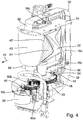
- an LED light module according to the invention is designated in its entirety by the reference symbol 10.
- the LED light module 10 is installed in a housing (not shown) of a motor vehicle headlight and is used to generate a predetermined light distribution which is emitted in a light exit direction 12 in front of the motor vehicle.
- the light distribution can be a low beam, a high beam, a position light, a cornering light and / or any other light function (eg a welcome light).
- the LED light module 10 is particularly compact, can be handled separately as a unit, and can be installed quickly and inexpensively.
- the light module 10 has particularly low tolerances, so that the specified light distribution can be generated with particularly high accuracy.
- the LED light module 10 initially comprises at least one LED 14a, 14b for emitting light.
- the LED light module also includes 10 a holding frame 16 with at least one bearing point 18, 20 and a reflector assembly 22 with a reflector 24 for reflecting at least part of the light emitted by the LEDs 14a, 14b.
- the reflector assembly 22 is mounted in the holding frame 16 so as to be rotatable about a vertical axis of rotation 26 by means of the bearing points 18, 20.
- the LED light module 10 comprises an electrical drive unit 28 for rotating the reflector assembly 22 about the vertical axis of rotation 26.
- the light module 10 comprises an electrical control unit 30 for controlling the drive unit 28 and / or the LEDs 14a, 14b.
- the light module 10 is designed, for example, to implement a welcome light function (can be automatically activated after actuating a door opener of the motor vehicle or after locking the motor vehicle). Further light functions that could be implemented with the light module 10 are, for example, position light, additional low beam and additional high beam (together with another low beam or high beam, produce a low beam or high beam) and cornering light.
- a welcome light function can be automatically activated after actuating a door opener of the motor vehicle or after locking the motor vehicle.
- Further light functions that could be implemented with the light module 10 are, for example, position light, additional low beam and additional high beam (together with another low beam or high beam, produce a low beam or high beam) and cornering light.
- the holding frame 16 is along a vertical sectional plane (in the plane of the drawing Figure 1 or parallel to it), which runs parallel to or congruent with the vertical axis of rotation 26, divided into two frame halves 16a, 16b (cf. Figure 7 ).
- the two bearing points 18, 20 for the reflector assembly are formed to one part 18a, 20a in one frame half 16a and another part 18b, 20b in the other frame half 16b.
- the bearings 18, 20 are thus formed by assembling the two frame halves 16a, 16b.
- the frame halves 16a, 16b are fastened to one another after assembly, for example by means of screws 16c.
- the light source 14b is preferably arranged in a stationary manner on the holding frame 16 and the reflector assembly 22 rotates around the focal point of the light source 14b, that is, the axis of rotation 26 runs through the light source 14b.
- the reflector assembly 22 can rotate by up to +/- 45 ° as required. Even a rotation of the reflector assembly 22 through 360 ° is possible.
- the LEDs 14a, 14b are stationary relative to the holding frame 16 and are arranged in the LED light module 10 in a contactless manner relative to the reflector assembly 22.
- the LEDs 14a, 14b are attached to a circuit board 34 (so-called PCB) and contact is made via it.
- the circuit board 34 is in turn fastened to an underside of an upper section of the holding frame 16.
- the holding frame 16 consists of a material that conducts heat well, in particular a metal, particularly preferably aluminum, so that it serves not only to hold the LEDs 14a, 14b but also as a heat sink for removing heat from the LEDs 14a, 14b.
- the LEDs 14a, 14b are arranged above the reflector assembly 22, so that they emit light with a Lambertian emission characteristic in a downward direction in a 180 ° half-space below the LEDs 14a, 14b Emit in the direction of a reflection surface of the reflector 24.
- the LEDs 14a, 14b are electrically contacted by means of flexible ribbon lines 32, which run at least over part of their longitudinal extent on the outside along the holding frame 16 and are fastened to it.
- the LEDs preferably include an RGB LED 14a for emitting light of any color.
- the RGB-LED 14a can be arranged outside a focal point of the reflector 24 of the reflector assembly 22.
- the RGB-LED 14a is preferably arranged on the circuit board 34 behind the rotating reflector assembly 22 and illuminates an interior area of the headlight.
- colored light can be emitted to implement a welcome light function (can be automatically activated after actuating a door opener of the motor vehicle or after locking the motor vehicle).
- the reflector assembly 22 can rotate about the vertical axis of rotation 26 during the welcome light function, for example by 180 °.
- the LEDs preferably comprise a high-power LED 14b for emitting white light. This is arranged in a focal point of the reflector 24 of the reflector assembly 22. Of course, several high-power LEDs 14b can also be arranged in or near the focal point of the reflector 24. With the aid of such an LED 14b, for example, a low beam function can be implemented. A horizontal (symmetrical or asymmetrical) light-dark boundary of the low beam can be implemented, for example, by a corresponding shape of the reflector 24. Alternatively, it would also be conceivable, at least for the duration of a low beam function, to arrange a diaphragm arrangement (not shown) in the beam path of the light reflected by the reflector 24 in the light exit direction 12.
- An edge of the diaphragm arrangement could then by means of projection optics (not shown) that For example, designed as a projection lens, can be projected as a light-dark boundary onto a roadway in front of the motor vehicle.
- the projection optics could rotate together with the reflector assembly 12.
- the focal point of the reflector 24, in which the high-performance LED 14b is arranged be on the vertical axis of rotation 26 of the reflector assembly 22 lies.
- the reflector assembly 22 has a light disk 40 in the beam path of the light reflected by the reflector 24, through which the reflected light passes and into which light can be coupled via at least one of its side surfaces, which is at least partially in the direction of the reflector 24 reflected and in the light exit direction 12 passing through the lens 40 exits the lens 40 so that it appears as a luminous surface.
- a position light can be implemented by the light emerging from the lens 40.
- the light disk 40 is assigned a light guide 42 which surrounds the light disk 40 on the circumferential side at least around several of its side surfaces.
- Light can be coupled into the end faces of the light guide 42, which at least partially emerges from the light guide 42 in the direction of the side faces of the light disk 40 and couples into the light disk 40 via the side faces.
- the light coupled into the light guide 42 is preferably generated by one or more LEDs 14c. These can be arranged on the same circuit board 34 as the other LEDs 14a, 14b. The light emitted by the LEDs 14c therefore only hits the end faces of the light guide 42 when the reflector assembly 22 is in its starting position, in which it is directed straight ahead in the direction of travel and not rotated about the axis of rotation 26.
- the holding frame 16 preferably has lateral bearing points 36 (cf. Figure 7 ), by means of which the entire LED light module 10 can be pivoted about a horizontal axis of rotation 38.
- a headlight range control can be implemented by vertically pivoting the reflector assembly 10 about the horizontal axis of rotation 38.
- a light function for example an 'additional high beam'
- the high beam would consist of a raised low beam.
- the LED light module 10 has a gear.
- the drive unit 28 is designed as an electric motor, particularly preferably as a stepping motor, and the gear 44 is fastened in a rotationally fixed manner on a motor shaft 46 of the motor 28.
- the reflector assembly 22 is assigned a further gear 48 of the transmission.
- the gear is designed as a tensioned gear to minimize / avoid backlash.
- the two frame halves 16a, 16b have depressions 50a, 50b in which, after assembly of the two frame halves 16a, 16b, the gears 44, 48 are added.
- the reflector assembly 22 is assigned at least one magnet 52 and the drive unit 28 or the holding frame 16 is assigned a magnetic field-sensitive sensor 54, the two frame halves 16a, 16b having recesses 50c in which, after the two frame halves 16a, 16b have been assembled, the magnet 52 and the sensor 54 are included (cf. Figures 7 and 8th ).
- the sensor 54 is arranged on a circuit board 56, for example.
- the sensor 54 is preferably designed as a Hall sensor.
- the magnet 52 is preferably designed as a ring magnet which is an integral part of the further gearwheel 48 or which forms at least one unit with it. Thus, the magnet 52 is also received in the recesses 50b of the frame halves 16a, 16b, in which the further gearwheel 48 is also received.
- the drive unit 28 is preferably fastened on the outside of the holding frame 16.
- the holding frame 16 has an opening 58 for a movable actuating element of the drive unit 28, in particular for the motor shaft 46 of an electric motor.
- One part 58a of the opening 58 is in one frame half 16a and another part (in Figure 7 not visible) in the other frame half 16b.
- the opening 58 is thus formed by assembling the two frame halves 16a, 16b.
- the drive of the further gearwheel 48 of the transmission assigned to the reflector assembly 22 can take place directly through the first gearwheel 44, or else indirectly via at least one further gearwheel.
- the transmission has two further gears 60a, 60b (cf. Figure 5 ).
- the corresponding bearing points 62, 64 are formed to one part 62a, 64a in one frame half 16a and to another part (not shown) in the other frame half 16b and the bearing points 62, 64 are formed by assembling the form two frame halves 16a, 16b.
- control unit 30 be fastened on the outside of the holding frame 16.
- the control unit 30 comprises, for example, a printed circuit board (so-called PCB) on which electrical and electronic components, sockets, plugs, contact pins, etc. can be arranged and contacted.
- the control unit 30 is preferably screwed to the outside of the holding frame 16. In the illustrated example, the control unit 30 is attached to an underside of a lower section of the holding frame 16.
- a light module group 100 is shown in each case, which comprises a plurality of LED light modules 10 arranged next to one another from the Figures 1 to 8 having.
- the light module group 100 comprises three light modules 10 arranged next to one another.
- the light module group 100 comprises a carrier element 102 which is permanently connected to a housing of the headlight in which the light module group 100 is installed and which has recesses 104 for receiving the three LED light modules 10 .
- the light modules 10 are each mounted pivotably about a horizontal axis of rotation 38 via their respective lateral bearing points 36 on the carrier element 102.
- the horizontal axes 38 do not have to be congruent. Nor do they all have to be on the same horizontal plane. In the example, the axes 38 are arranged on different horizontal planes (cf. Figure 10 ) and run backwards (in the drawing plane of the Figure 9 ) offset to each other.
- the three light modules 10 are pivoted together by the same amount.
- a common distribution linkage 106 is articulated to the top of each LED light module 10 or to an upper section of the holding frame 16.
- the distributor linkage 106 is moved parallel to the light exit direction 12 by means of an actuator (not shown), which is designed, for example, as an electric motor, preferably as a stepper motor, or as a magnet. This movement of the linkage 106 leads to a vertical pivoting of the light modules 10.
- an actuator not shown
Landscapes
- Engineering & Computer Science (AREA)
- General Engineering & Computer Science (AREA)
- Physics & Mathematics (AREA)
- Microelectronics & Electronic Packaging (AREA)
- Optics & Photonics (AREA)
- Non-Portable Lighting Devices Or Systems Thereof (AREA)
- Lighting Device Outwards From Vehicle And Optical Signal (AREA)
Description
- Die vorliegende Erfindung betrifft ein LED-Lichtmodul für einen Kraftfahrzeugscheinwerfer. Das Lichtmodul umfasst mindestens eine LED zum Aussenden von Licht, eine in einem Halterahmen mittels mindestens einer Lagerstelle um eine vertikale Drehachse drehbar gelagerte Reflektorbaugruppe mit einem Reflektor zum Reflektieren zumindest eines Teils des ausgesandten Lichts, eine elektrische Antriebseinheit zum Drehen der Reflektorbaugruppe um die vertikale Drehachse, und eine elektrische Steuereinheit zur Steuerung der Antriebseinheit.
- Aus der
CN 105387410 ist ein LED-Lichtmodul der eingangs genannten Art bekannt. Dort wird vorgeschlagen, mehrere solcher LED-Lichtmodule nebeneinander anzuordnen und zu einer Lichtmodulgruppe zusammenzufassen. Jedes LED-Lichtmodul für sich kann um eine vertikale Drehachse in horizontaler Richtung gedreht werden, um eine Kurvenlichtfunktion zu realisieren. Alle LED-Lichtmodule der Lichtmodulbaugruppe können gemeinsam um horizontale Drehachsen in vertikaler Richtung verschwenkt werden, um eine Leuchtweitenregulierung zu realisieren. -
US 2008/247182 A1 ,WO 2014/008523 A1 ,EP 1 854 665 A1 ,DE 10 2011 003908 A1 ,US 2009/034279 A1 undDE 10 2011 003910 A1 offenbaren jeweils ein Lichtmodul für einen Kraftfahrzeugscheinwerfer. - Ausgehend von dem beschriebenen Stand der Technik liegt der vorliegenden Erfindung die Aufgabe zugrunde, ein LED-Lichtmodul zu schaffen, das besonders einfach und kompakt aufgebaut ist, das leicht zu montieren ist und bei dem möglichst geringe Toleranzen im funktionalen Zusammenspiel der verschiedenen Bauteile des Lichtmoduls erreicht werden können.
- Zur Lösung dieser Aufgabe wird ausgehend von dem LED-Lichtmodul der eingangs genannten Art vorgeschlagen, dass der Halterahmen entlang einer vertikalen Schnittebene, die parallel zu oder deckungsgleich mit der vertikalen Drehachse verläuft, in zwei Rahmenhälften unterteilt ist, wobei die mindestens eine Lagerstelle für die Reflektorbaugruppe zu einem Teil in der einen Rahmenhälfte und zu einem anderen Teil in der anderen Rahmenhälfte ausgebildet ist und sich die mindestens eine Lagerstelle durch Zusammensetzen der beiden Rahmenhälften bildet.
- Ein Vorteil des erfindungsgemäßen LED-Lichtmoduls ist es, dass die drehbare Reflektorbaugruppe besonders einfach und schnell in der mindestens einen Lagerstelle des Halterahmens angeordnet werden kann, indem einfach die beiden Rahmenhälften von gegenüberliegenden Seiten aus um mindestens einen entsprechenden Lagerabschnitt der Reflektorbaugruppe gelegt und die Rahmenhälften aneinander befestigt werden. Die jeweiligen Lagerstellenteile in den beiden Rahmenhälften bilden dann zusammen die mindestens eine Lagerstelle des Halterahmens, in der der entsprechende mindestens eine Lagerabschnitt der Reflektorbaugruppe drehbar gelagert ist. Vorzugsweise befindet sich der mindestens eine Lagerabschnitt an der Unterseite der Reflektorbaugruppe. Dementsprechend ist die Lagerstelle an einem unteren Abschnitt des Halterahmens ausgebildet. Es wird vorgeschlagen, dass die Reflektorbaugruppe ausschließlich um diesen mindestens einen Lagerabschnitt an unteren Abschnitt des Halterahmens drehbar gelagert ist. Eine drehbare Lagerung auf der gegenüberliegenden Seite oberhalb der Reflektorbaugruppe in einer zusätzlichen Lagerstelle in einem oberen Abschnitt des Halterahmens kann entfallen.
- Dadurch ist es möglich, die mindestens eine LED oberhalb der Reflektorbaugruppe an dem Halterahmen zu befestigen. Vorzugsweise ist die mindestens eine LED selbst auf einer Platine (sog. PCB) angeordnet und die Platine dann an dem Halterahmen befestigt. Die mindestens eine LED kann dann ungehindert Licht in eine nach unten gerichtete Hauptabstrahlrichtung auf die Reflexionsfläche des Reflektors aussenden. Bei einer Ausgestaltung des Halterahmens aus einem gut Wärme leitfähigen Material, bspw. einem Metall, insbesondere Aluminium, kann der Halterahmen gleichzeitig auch als Kühlkörper dienen. Vorzugsweise sind die beiden Rahmenhälften aus einem Aluminiumdruckguss hergestellt. Die mindestens eine LED kann mittels Flexbandleitungen elektrisch kontaktiert werden, die außen entlang des Halterahmens geführt und befestigt sein können, so dass an der Unterseite des Halterahmens ein Steckerkontakt ausgebildet werden kann, an den ein Steuergerät für die mindestens eine LED angeschlossen werden kann, um die mindestens eine LED mit elektrischer Energie zu versorgen.
- Die Verwendung eines in zwei Rahmenhälften unterteilten Halterahmens hat zudem den Vorteil, dass in den Rahmenhälften Vertiefungen ausgebildet werden können, die nach dem Zusammensetzen der Rahmenhälften Kammern bilden, in denen verschiedene Bauteile des LED-Lichtmoduls untergebracht werden können, so dass sich eine besonders kompakte und leicht handhabbare, sowie ästhetisch ansprechende LED-Lichtmodul-Baugruppe ergibt. Bauteile des LED-Lichtmoduls, die nicht in den Kammern des Halterahmens untergebracht werden (bspw. aus Platzgründen oder aus thermischen Gründen), können außen an dem Halterahmen befestigt werden.
- Gemäß einer vorteilhaften Weiterbildung der vorliegenden Erfindung wird vorgeschlagen, dass die Reflektorbaugruppe in dem Halterahmen mittels zweier Lagerstellen um die vertikale Drehachse drehbar gelagert ist, wobei die beiden Lagerstellen unterhalb der Reflektorbaugruppe an einem unteren Abschnitt des Halterahmens entlang der vertikalen Drehachse versetzt zueinander angeordnet sind. Durch die versetzt zueinander angeordneten Lagerstellen ist - trotz der lediglich einseitigen Lagerung der Reflektorbaugruppe in dem Halterahmen - eine besonders toleranz- und spielfreie Lagerung der Reflektorbaugruppe möglich.
- Gemäß einer vorteilhaften Ausgestaltung der Erfindung wird vorgeschlagen, dass der Antriebseinheit mindestens ein Zahnrad eines Getriebes zugeordnet ist, das zur Umwandlung einer Betätigungsbewegung der Antriebseinheit in eine entsprechende Drehbewegung der Reflektorbaugruppe vorgesehen ist, und dass der Reflektorbaugruppe mindestens ein weiteres Zahnrad des Getriebes zugeordnet ist, wobei die beiden Rahmenhälften Vertiefungen aufweisen, in denen nach dem Zusammensetzen der beiden Rahmenhälften die Zahnräder aufgenommen sind. Die Antriebseinheit ist vorzugsweise als ein Elektromotor, insbesondere als ein elektrischer Schrittmotor ausgebildet. Über das Getriebe mit den Zahnrädern wird eine Drehbewegeung der Motorwelle (Betätigungsbewegung) in eine entsprechende Drehbewegung der Reflektorbaugruppe um die vertikale Achse umgewandelt. Die Reflektorbaugruppe kann um bis zu 360° um die vertikale Drehachse rotieren.
- Des Weiteren wird vorgeschlagen, dass der Reflektorbaugruppe mindestens ein Magnet und der Antriebseinheit ein magnetfeldsensitiver Sensor zugeordnet ist, wobei die beiden Rahmenhälften Vertiefungen aufweisen, in denen nach dem Zusammensetzen der beiden Rahmenhälften der Magnet und der Sensor aufgenommen sind. Der Magnet ist insbesondere als ein Ringmagnet ausgebildet. Der Sensor kann bspw. als ein Hall-Sensor ausgebildet sein, der ein sich wechselndes Magnetfeld bei Drehung des Ringmagnets zusammen mit der Reflektorbaugruppe um die vertikale Drehachse detektieren kann. Eine Verarbeitungseinheit, die integraler Bestandteil des Sensors sein kann, kann daraus dann einen Relativ- oder Absolutwert für die Drehposition und Ausrichtung der Reflektorbaugruppe ermitteln. Selbstverständlich wäre es auch denkbar, dass der Reflektorbaugruppe der magnetfeldsensitive Sensor und der Antriebseinheit der mindestens eine Magnet zugeordnet ist.
- Gemäß einer anderen vorteilhaften Weiterbildung der Erfindung wird vorgeschlagen, dass die Antriebseinheit außen an dem Halterahmen befestigt ist und der Halterahmen eine Öffnung für ein bewegbares Betätigungselement der Antriebseinheit aufweist, wobei die Öffnung für das Betätigungselement der Antriebseinheit zu einem Teil in der einen Rahmenhälfte und zu einem anderen Teil in der anderen Rahmenhälfte ausgebildet ist und sich die Öffnung durch Zusammensetzen der beiden Rahmenhälften bildet. Die Antriebseinheit ist vorzugsweise als ein Elektromotor ausgebildet. Gemäß dieser Weiterbildung bilden die beiden Rahmenhälften des Halterahmens also eine Öffnung, durch die eine Motorwelle des Elektromotors hindurchgeführt werden kann. Auf der Motorwelle ist ein erstes Zahnrad des Getriebes drehfest befestigt, welches in einer Kammer im Inneren des zusammengesetzten Halterahmens angeordnet ist. Auch hier ergibt sich eine besonders einfache und zeitsparende Montage der Antriebseinheit, da die Rahmenhälften von gegenüberliegenden Seiten um die Motorwelle gelegt werden können, so dass das erste Zahnrad in einer Kammer im Inneren des Halterahmens und die Motorwelle in der Öffnung aufgenommen wird.
- Der Antrieb des der Reflektorbaugruppe zugeordneten weiteren Zahnrads des Getriebes kann unmittelbar durch das erste Zahnrad erfolgen, oder aber mittelbar über mindestens ein weiteres Zahnrad. Das mindestens eine weitere Zahnrad, welches die Drehbewegung des ersten Zahnrads der Motorwelle auf das weitere Zahnrad der Reflektorbaugruppe überträgt, ist vorzugsweise ebenfalls in einer entsprechenden Lagerstelle in dem Halterahmen gelagert. Auch für dieses mindestens eine weitere Zahnrad ist es vorteilhaft, wenn die entsprechende Lagerstelle zu einem Teil in der einen Rahmenhälfte und zu einem anderen Teil in der anderen Rahmenhälfte ausgebildet ist und sich die entsprechende Lagerstelle durch Zusammensetzen der beiden Rahmenhälften bildet.
- Es wird vorgeschlagen, dass die Steuereinheit außen an dem Halterahmen befestigt ist. Die Steuereinheit umfasst bspw. eine Leiterplatte (sog. PCB) auf der elektrische und elektronische Bauelemente, Buchsen, Stecker, Kontaktstifte u.a. angeordnet und kontaktiert sein können. Die Steuereinheit wird vorzugsweise an die Außenseite des Halterahmens geschraubt. Besonders bevorzugt ist sie an der Unterseite eines unteren Abschnitts des Halterahmens angeordnet.
- Gemäß einer weiteren vorteilhaften Ausgestaltung der Erfindung wird vorgeschlagen, dass die mindestens eine LED relativ zu dem Halterahmen feststehend und relativ zu der Reflektorbaugruppe berührungslos in dem LED-Lichtmodul angeordnet ist. Vorzugsweise ist die mindestens eine LED bei in den Kraftfahrzeugscheinwerfer eingebautem LED-Lichtmodul oberhalb der Reflektorbaugruppe angeordnet, so dass sie in einer nach unten gerichteten Hauptabstrahlrichtung Licht mit einer lambert'schen Abstrahlcharakteristik in einen 180°-Halbraum unterhalb der LED in Richtung der Reflexionsfläche des Reflektors aussendet. Die mindestens eine LED ist vorzugsweise auf einer Platine (sog. PCB) befestigt und elektrisch kontaktiert. Die Platine mit der mindestens einen LED kann an dem Halterahmen befestigt werden. Wenn dieser aus einem gut Wärme leitfähigen Material besteht, kann der Halterahmen gleichzeitig als Kühlkörper für die mindestens eine LED dienen. Bei Drehung der Reflektorbaugruppe um die vertikale Achse dreht sich der Reflektor relativ zu der mindestens einen LED.
- Vorteilhafterweise ist die mindestens eine LED mittels Flexbandleitungen elektrisch kontaktiert, die außen entlang des Halterahmens verlaufen. Insbesondere sind die Flexbandleitungen entlang der Außenseite des Halterahmens geführt und zumindest punktuell daran befestigt.
- Gemäß einer vorteilhaften Weiterbildung der Erfindung wird vorgeschlagen, dass die mindestens eine LED eine RGB-LED zum Aussenden von Licht einer beliebigen Farbe umfasst. Eine solche RGB-LED kann Licht einer nahezu beliebigen Farbe aussenden. Die RGB-LED kann außerhalb eines Brennpunkts des Reflektors der Reflektorbaugruppe angeordnet sein. Mit Hilfe der RGB-LED kann bspw. farbiges Licht zur Realisierung einer Begrüßungslichtfunktion (kann nach Betätigung eines Türöffners des Kraftfahrzeugs oder nach einem Verschließen des Kraftfahrzeugs automatisch aktiviert werden) ausgesandt werden. Zusätzlich kann die Reflektorbaugruppe während der Begrüßungslichtfunktion um die vertikale Drehachse rotieren, so dass mit dem erfindungsgemäßen LED-Lichtmodul völlig neue Licht- bzw. Leuchtenfunktionen realisiert werden können.
- Gemäß einer anderen vorteilhaften Weiterbildung der Erfindung wird vorgeschlagen, dass die mindestens eine LED eine Hochleistungs-LED zum Aussenden von weißem Licht umfasst, die in einem Brennpunkt des Reflektors angeordnet ist. Selbstverständlich können auch mehrere Hochleistungs-LEDs in oder nahe dem Brennpunkt des Reflektors angeordnet sein. Mit Hilfe einer solchen LED kann bspw. eine Abblendlichtfunktion realisiert werden. Eine horizontale oder asymmetrische Helldunkelgrenze des Abblendlichts kann bspw. durch eine entsprechende Form des Reflektors realisiert werden. Alternativ wäre es auch denkbar, zumindest für die Dauer einer Abblendlichtfunktion, eine Blendenanordnung in dem Strahlengang des von dem Reflektor reflektierten Lichts anzuordnen. Eine Kante der Blendenanordnung kann mittels einer Projektionsoptik, die bspw. als eine Projektionslinse ausgebildet ist, als Helldunkelgrenze auf eine Fahrbahn vor dem Kraftfahrzeug projiziert werden.
- Damit während der Realisierung einer Kurvenlichtfunktion des LED-Lichtmoduls die Lichtstärkeverteilung und die Kontur der Lichtverteilung weitgehend konstant bleibt, wird vorgeschlagen, dass der Brennpunkt des Reflektors, in dem die Hochleistungs-LED angeordnet ist, auf der vertikalen Drehachse der Reflektorbaugruppe liegt.
- Vorteilhafterweise hat der Halterahmen seitliche Lagerstellen, mittels der das LED-Lichtmodul um eine horizontale Drehachse verschwenkbar ist. Durch ein vertikales Verschwenken der Reflektorbaugruppe kann eine Leuchtweitenregulierung realisiert werden. Außerdem kann durch Anheben der Reflektorbaugruppe während sie ein Abblendlicht erzeugt, eine Fernlichtfunktion realisiert werden. In diesem Fall könnte die Reflektorbaugruppe ein 'Zusatzfernlicht' erzeugen, das zusammen mit einer anderen Fernlicht-Lichtverteilung eine Fernlichtfunktion realisiert.
- Des Weiteren wird vorgeschlagen, dass die Reflektorbaugruppe im Strahlengang des von dem Reflektor reflektierten Lichts eine Lichtscheibe aufweist, durch die das reflektierte Licht hindurchtritt und in die über mindestens eine ihrer Seitenflächen Licht einkoppelbar ist, das zumindest teilweise in Richtung des von dem Reflektor reflektierten und durch die Lichtscheibe hindurchtretenden Lichts aus der Lichtscheibe austritt, so dass diese als eine leuchtende Fläche erscheint. Durch das aus der Lichtscheibe austretende Licht kann ein Positionslicht realisiert werden. Das seitlich in die Lichtscheibe eingekoppelte Licht wird vorzugsweise von einer oder mehreren LEDs erzeugt.
- Vorteilhafterweise hat die Lichtscheibe zumindest um mehrere ihrer Seitenflächen herum einen Lichtleiter, in den Licht einkoppelbar ist, das zumindest teilweise in Richtung der Seitenflächen der Lichtscheibe aus dem Lichtleiter austritt und über die Seitenflächen in die Lichtscheibe einkoppelt.
- Weitere Merkmale und Vorteile der vorliegenden Erfindung werden nachfolgend unter Bezugnahme auf die Figuren näher erläutert. Die vorliegende Erfindung kann die nachfolgend anhand eines bevorzugten Ausführungsbeispiels beschrieben und in den Figuren gezeigten Merkmale auch separat voneinander oder in einer anderen Kombination als hier beschrieben aufweisen. In den Figuren zeigen:
- Figur 1
- ein erfindungsgemäßes LED-Lichtmodul gemäß einer bevorzugten Ausführungsform in einer Seitenansicht teilweise im Schnitt;
- Figur 2
- das LED-Lichtmodul aus
Figur 1 in einer Ansicht von schräg unten; - Figur 3
- das LED-Lichtmodul aus
Figur 1 in einer Seitenansicht; - Figur 4
- das LED-Lichtmodul aus
Figur 1 in einer perspektivischen Ansicht teilweise im Schnitt; - Figur 5
- eine Antriebseinheit, ein Getriebe und eine Reflektorbaugruppe des LED-Lichtmoduls aus
Figur 1 ; - Figur 6
- eine Reflektorbaugruppe des LED-Lichtmoduls aus
Figur 1 ; - Figur 7
- das LED-Lichtmodul aus
Figur 1 in einer Explosionsdarstellung; - Figur 8
- einen Halterahmen und eine Reflektorbaugruppe des LED-Lichtmoduls aus
Figur 1 in einer Explosionsdarstellung; - Figur 9
- eine Lichtmodulgruppe umfassend drei nebeneinander angeordnete LED-Lichtmodule aus
Figur 1 in einer perspektivischen Ansicht; und - Figur 10
- die Lichtmodulgruppe aus
Figur 7 in einer Ansicht von vorne entgegen einer Lichtaustrittsrichtung. - In
Figur 1 ist ein erfindungsgemäßes LED-Lichtmodul in seiner Gesamtheit mit dem Bezugszeichen 10 bezeichnet. Das LED-Lichtmodul 10 wird in ein Gehäuse (nicht dargestellt) eines Kraftfahrzeugscheinwerfers eingebaut und dient zur Erzeugung einer vorgegebenen Lichtverteilung, die in eine Lichtaustrittsrichtung 12 vor das Kraftfahrzeug ausgesandt wird. Die Lichtverteilung kann ein Abblendlicht, ein Fernlicht, ein Positionslicht, ein Kurvenlicht und/oder eine beliebig andere Lichtfunktion (z.B. ein Begrüßungslicht) sein. Das LED-Lichtmodul 10 ist besonders kompakt aufgebaut, als eine Einheit separat handhabbar und kann kostengünstig und schnell montiert werden. Zudem weist das Lichtmodul 10 aufgrund seiner besonderen Konstruktion besonders geringe Toleranzen auf, so dass die vorgegebene Lichtverteilung mit besonders hoher Genauigkeit erzeugt werden kann. - Das LED-Lichtmodul 10 umfasst zunächst mindestens eine LED 14a, 14b zum Aussenden von Licht. Ferner umfasst das LED-Lichtmodul 10 einen Halterahmen 16 mit mindestens einer Lagerstelle 18, 20 sowie eine Reflektorbaugruppe 22 mit einem Reflektor 24 zum Reflektieren zumindest eines Teils des von den LEDs 14a, 14b ausgesandten Lichts. Die Reflektorbaugruppe 22 ist mittels der Lagerstellen 18, 20 um eine vertikale Drehachse 26 drehbar in dem Halterahmen 16 gelagert. Des Weiteren umfasst das LED-Lichtmodul 10 eine elektrische Antriebseinheit 28 zum Drehen der Reflektorbaugruppe 22 um die vertikale Drehachse 26. Schließlich umfasst das Lichtmodul 10 eine elektrische Steuereinheit 30 zur Steuerung der Antriebseinheit 28 und/oder der LEDs 14a, 14b.
- Das Lichtmodul 10 ist bspw. zur Realisierung einer Begrüßungslichtfunktion (kann nach Betätigung eines Türöffners des Kraftfahrzeugs oder nach einem Verschließen des Kraftfahrzeugs automatisch aktiviert werden) ausgebildet. Weitere Lichtfunktionen, die mit dem Lichtmodul 10 realisiert werden könnten, sind bspw. Positionslicht, Zusatz-Abblend- und Zusatz-Fernlicht (realisieren zusammen mit einem anderen Abblendlicht oder Fernlicht ein Abblendlicht bzw. ein Fernlicht) und Kurvenlicht.
- Der Halterahmen 16 ist entlang einer vertikalen Schnittebene (in der Zeichenebene der
Figur 1 bzw. parallel dazu), die parallel zu oder deckungsgleich mit der vertikalen Drehachse 26 verläuft, in zwei Rahmenhälften 16a, 16b unterteilt (vgl.Figur 7 ). Die beiden Lagerstellen 18, 20 für die Reflektorbaugruppe sind zu einem Teil 18a, 20a in der einen Rahmenhälfte 16a und zu einem anderen Teil 18b, 20b in der anderen Rahmenhälfte 16b ausgebildet. Die Lagerstellen 18, 20 bilden sich also durch Zusammensetzen der beiden Rahmenhälften 16a, 16b. Die Rahmenhälften 16a, 16b werden nach dem Zusammensetzen aneinander befestigt, bspw. mittels Schrauben 16c. Durch horizontales Drehen der Reflektorbaugruppe 22 um die vertikale Drehachse 26 kann eine Kurvenlichtfunktion realisiert werden. Dabei steht die Lichtquelle 14b vorzugsweise feststehend am Halterahmen 16 angeordnet und die Reflektorbaugruppe 22 dreht sich um den Brennpunkt der Lichtquelle 14b, das heißt die Drehachse 26 verläuft durch die Lichtquelle 14b. Die Reflektorbaugruppe 22 kann sich je nach Erfordernis um bis zu +/-45° drehen. Selbst eine Rotation der Reflektorbaugruppe 22 um 360° ist möglich. - Die LEDs 14a, 14b sind relativ zu dem Halterahmen 16 feststehend und relativ zu der Reflektorbaugruppe 22 berührungslos in dem LED-Lichtmodul 10 angeordnet. Insbesondere sind die LEDs 14a, 14b auf einer Platine 34 (sog. PCB) befestigt und darüber kontaktiert. Die Platine 34 ist ihrerseits an einer Unterseite eines oberen Abschnitts des Halterahmens 16 befestigt. Der Halterahmen 16 besteht aus einem gut Wärme leitenden Material, insbesondere aus einem Metall, besonders bevorzugt aus Aluminium, so dass er außer zur Halterung der LEDs 14a, 14b auch als Kühlkörper zum Abtransport von Wärme der LEDs 14a, 14b dient. Die LEDs 14a, 14b sind bei einem in den Kraftfahrzeugscheinwerfer eingebauten LED-Lichtmodul 10 oberhalb der Reflektorbaugruppe 22 angeordnet, so dass sie in einer nach unten gerichteten Hauptabstrahlrichtung Licht mit einer lambert'schen Abstrahlcharakteristik in einen 180°-Halbraum unterhalb der LEDs 14a, 14b in Richtung einer Reflexionsfläche des Reflektors 24 aussenden. Die LEDs 14a, 14b sind mittels Flexbandleitungen 32 elektrisch kontaktiert, die zumindest über einen Teil ihrer Längserstreckung außen entlang des Halterahmens 16 verlaufen und daran befestigt sind.
- Die LEDs umfassen vorzugsweise eine RGB-LED 14a zum Aussenden von Licht einer beliebigen Farbe. Die RGB-LED 14a kann außerhalb eines Brennpunkts des Reflektors 24 der Reflektorbaugruppe 22 angeordnet sein. Vorzugsweise ist die RGB-LED 14a auf der Platine 34 hinter der rotierenden Reflektorbaugruppe 22 angeordnet und beleuchtet einen Innenbereich des Scheinwerfers. Mit Hilfe der RGB-LED 14a kann bspw. farbiges Licht zur Realisierung einer Begrüßungslichtfunktion (kann nach Betätigung eines Türöffners des Kraftfahrzeugs oder nach einem Verschließen des Kraftfahrzeugs automatisch aktiviert werden) ausgesandt werden. Zusätzlich kann die Reflektorbaugruppe 22 während der Begrüßungslichtfunktion um die vertikale Drehachse 26 rotieren, bspw. um 180°. Mit dem erfindungsgemäßen LED-Lichtmodul 10 können also völlig neue Licht- bzw. Leuchtenfunktionen realisiert werden.
- Ferner umfassen die LEDs vorzugsweise eine Hochleistungs-LED 14b zum Aussenden von weißem Licht. Diese ist in einem Brennpunkt des Reflektors 24 der Reflektorbaugruppe 22 angeordnet. Selbstverständlich können auch mehrere Hochleistungs-LEDs 14b in oder nahe dem Brennpunkt des Reflektors 24 angeordnet sein. Mit Hilfe einer solchen LED 14b kann bspw. eine Abblendlichtfunktion realisiert werden. Eine horizontale (symmetrische oder asymmetrische) Helldunkelgrenze des Abblendlichts kann bspw. durch eine entsprechende Form des Reflektors 24 realisiert werden. Alternativ wäre es auch denkbar, zumindest für die Dauer einer Abblendlichtfunktion, eine Blendenanordnung (nicht dargestellt) in dem Strahlengang des von dem Reflektor 24 in Lichtaustrittsrichtung 12 reflektierten Lichts anzuordnen. Eine Kante der Blendenanordnung könnte dann mittels einer Projektionsoptik (nicht dargestellt), die bspw. als eine Projektionslinse ausgebildet ist, als Helldunkelgrenze auf eine Fahrbahn vor dem Kraftfahrzeug projiziert werden. Die Projektionsoptik könnte als Designteil zusammen mit der Reflektorbaugruppe 12 rotieren.
- Damit während der Realisierung einer Kurvenlichtfunktion des LED-Lichtmoduls 10 eine Lichtstärkeverteilung und eine Kontur der Lichtverteilung weitgehend konstant bleibt, wird vorgeschlagen, dass der Brennpunkt des Reflektors 24, in dem die Hochleistungs-LED 14b angeordnet ist, auf der vertikalen Drehachse 26 der Reflektorbaugruppe 22 liegt.
- Des Weiteren wird vorgeschlagen, dass die Reflektorbaugruppe 22 im Strahlengang des von dem Reflektor 24 reflektierten Lichts eine Lichtscheibe 40 aufweist, durch die das reflektierte Licht hindurchtritt und in die über mindestens eine ihrer Seitenflächen Licht einkoppelbar ist, das zumindest teilweise in Richtung des von dem Reflektor 24 reflektierten und in Lichtaustrittsrichtung 12 durch die Lichtscheibe 40 hindurchtretenden Lichts aus der Lichtscheibe 40 austritt, so dass diese als eine leuchtende Fläche erscheint. Durch das aus der Lichtscheibe 40 austretende Licht kann ein Positionslicht realisiert werden.
- Vorzugsweise ist der Lichtscheibe 40 ein Lichtleiter 42 zugeordnet, der die Lichtscheibe 40 zumindest um mehrere ihrer Seitenflächen herum umfangsseitig umgibt. In Stirnflächen des Lichtleiters 42 kann Licht einkoppelt werden, das zumindest teilweise in Richtung der Seitenflächen der Lichtscheibe 40 aus dem Lichtleiter 42 austritt und über die Seitenflächen in die Lichtscheibe 40 einkoppelt. Das in den Lichtleiter 42 eingekoppelte Licht wird vorzugsweise von einer oder mehreren LEDs 14c erzeugt. Diese können auf der gleichen Platine 34 angeordnet sein wie die anderen LEDs 14a, 14b. Somit trifft das von den LEDs 14c ausgesandte Licht nur dann auf die Stirnflächen des Lichtleiters 42, wenn sich die Reflektorbaugruppe 22 in ihrer Ausgangsposition befindet, in der sie gerade aus in Fahrtrichtung gerichtet ist und nicht um die Drehachse 26 gedreht.
- Vorzugsweise hat der Halterahmen 16 seitliche Lagerstellen 36 (vgl.
Figur 7 ), mittels der das gesamte LED-Lichtmodul 10 um eine horizontale Drehachse 38 verschwenkbar ist. Durch ein vertikales Verschwenken der Reflektorbaugruppe 10 um die horizontale Drehachse 38 kann eine Leuchtweitenregulierung realisiert werden. Außerdem kann durch Anheben der Reflektorbaugruppe 10 während sie ein Abblendlicht erzeugt, eine Lichtfunktion (z.B. ein 'Zusatzfernlicht') realisiert werden, welche die Erzeugung eines Fernlichts unterstützt. In diesem Fall würde das Fernlicht also aus einem angehobenen Abblendlicht bestehen. - Damit die Antriebseinheit 28 eine Betätigungsbewegung in eine entsprechende Drehbewegung der Reflektorbaugruppe 22 um die vertikale Drehachse 26 umwandeln kann, verfügt das LED-Lichtmodul 10 über ein Getriebe. Dieses umfasst beispielsweise ein erstes Zahnrad 44, das der Antriebseinheit 28 zugeordnet ist. Insbesondere ist die Antriebseinheit 28 als ein Elektromotor, besonders bevorzugt als ein Schrittmotor ausgebildet, und ist das Zahnrad 44 drehfest auf einer Motorwelle 46 des Motors 28 befestigt. Der Reflektorbaugruppe 22 ist ein weiteres Zahnrad 48 des Getriebes zugeordnet. Das Getriebe ist zur Spielminimierung/-vermeidung als verspanntes Getriebe ausgeführt. Die beiden Rahmenhälften 16a, 16b weisen Vertiefungen 50a, 50b auf, in denen nach dem Zusammensetzen der beiden Rahmenhälften 16a, 16b die Zahnräder 44, 48 aufgenommen sind.
- Ferner ist der Reflektorbaugruppe 22 mindestens ein Magnet 52 und der Antriebseinheit 28 bzw. dem Halterahmen 16 ein magnetfeldsensitiver Sensor 54 zugeordnet, wobei die beiden Rahmenhälften 16a, 16b Vertiefungen 50c aufweisen, in denen nach dem Zusammensetzen der beiden Rahmenhälften 16a, 16b der Magnet 52 und der Sensor 54 aufgenommen sind (vgl.
Figuren 7 und8 ). Der Sensor 54 ist bspw. auf einer Platine 56 angeordnet. Vorzugsweise ist der Sensor 54 als ein Hallsensor ausgebildet. Der Magnet 52 ist vorzugsweise als ein Ringmagnet ausgebildet, der integraler Bestandteil mit dem weitern Zahnrad 48 ist oder mit diesem zumindest eine Einheit bildet. Somit wird der Magnet 52 ebenfalls in den Vertiefungen 50b der Rahmenhälften 16a, 16b aufgenommen, der denen auch das weitere Zahnrad 48 aufgenommen wird. - Vorzugsweise ist die Antriebseinheit 28 außen an dem Halterahmen 16 befestigt. Der Halterahmen 16 weist eine Öffnung 58 für ein bewegbares Betätigungselement der Antriebseinheit 28 auf, insbesondere für die Motorwelle 46 eines Elektromotors. Die Öffnung 58 ist zu einem Teil 58a in der einen Rahmenhälfte 16a und zu einem anderen Teil (in
Figur 7 nicht zu erkennen) in der anderen Rahmenhälfte 16b ausgebildet. Die Öffnung 58 bildet sich also durch Zusammensetzen der beiden Rahmenhälften 16a, 16b. - Der Antrieb des der Reflektorbaugruppe 22 zugeordneten weiteren Zahnrads 48 des Getriebes kann unmittelbar durch das erste Zahnrad 44 erfolgen, oder aber mittelbar über mindestens ein weiteres Zahnrad. In dem gezeigten Beispiel verfügt das Getriebe über zwei weitere Zahnräder 60a, 60b (vgl.
Figur 5 ). Die weiteren Zahnräder 60a, 60b, welche die Drehbewegung des ersten Zahnrads 44 der Motorwelle 46 auf das weitere Zahnrad 48 der Reflektorbaugruppe 22 übertragen, sind vorzugsweise ebenfalls in mindestens einer entsprechenden Lagerstelle 62, 64 in dem Halterahmen 16 gelagert. Auch dabei ist es vorteilhaft, wenn die entsprechenden Lagerstellen 62, 64 zu einem Teil 62a, 64a in der einen Rahmenhälfte 16a und zu einem anderen Teil (nicht dargestellt) in der anderen Rahmenhälfte 16b ausgebildet sind und sich die Lagerstellen 62, 64 durch Zusammensetzen der beiden Rahmenhälften 16a, 16b bilden. - Es wird vorgeschlagen, dass die Steuereinheit 30 außen an dem Halterahmen 16 befestigt ist. Die Steuereinheit 30 umfasst bspw. eine Leiterplatte (sog. PCB) auf der elektrische und elektronische Bauelemente, Buchsen, Stecker, Kontaktstifte u.a. angeordnet und kontaktiert sein können. Die Steuereinheit 30 wird vorzugsweise an die Außenseite des Halterahmens 16 geschraubt. In dem dargestellten Beispiel ist die Steuereinheit 30 an einer Unterseite eines unteren Abschnitts des Halterahmens 16 befestigt.
- In den
Figuren 9 und10 ist jeweils eine Lichtmodulgruppe 100 dargestellt, die mehrere nebeneinander angeordnete LED-Lichtmodule 10 aus denFiguren 1 bis 8 aufweist. In dem gezeigten Beispiel umfasst die Lichtmodulgruppe 100 drei nebeneinander angeordnete Lichtmodule 10. Die Lichtmodulgruppe 100 umfasst einen fest mit einem Gehäuse des Scheinwerfers, in den die Lichtmodulgruppe 100 eingebaut wird, verbundenes Trägerelement 102, das Aussparungen 104 zur Aufnahme der drei LED-Lichtmodule 10 aufweist. Die Lichtmodule 10 sind über ihre jeweiligen seitlichen Lagerstellen 36 an dem Trägerelement 102 jeweils um eine horizontale Drehachse 38 verschwenkbar gelagert. - Die horizontalen Achsen 38 müssen nicht deckungsgleich sein. Sie müssen sich auch nicht alle auf einer gemeinsamen horizontalen Ebene befinden. In dem Beispiel sind die Achsen 38 auf unterschiedlichen horizontalen Ebenen angeordnet (vgl.
Figur 10 ) und verlaufen nach hinten (in die Zeichenebene derFigur 9 ) versetzt zueinander. Die drei Lichtmodule 10 werden gemeinsam um den gleichen Betrag verschwenkt. Zu diesem Zweck ist ein gemeinsames Verteilergestänge 106 jeweils an der Oberseite der LED-Lichtmodule 10 bzw. einem oberen Abschnitt der Halterahmen 16 angelenkt. Das Verteilergestänge 106 wird mittels eines Aktors (nicht dargestellt), der bspw. als ein Elektromotor, vorzugsweise als ein Schrittmotor, oder als ein Magnet ausgebildet ist, parallel zur Lichtaustrittsrichtung 12 bewegt. Diese Bewegung des Gestänges 106 führt zu einem vertikalen Verschwenken der Lichtmodule 10. Dadurch kann eine Leuchtweitenregulierung oder eine Fernlichtfunktion durch Anheben einer Abblendlichtverteilung realisiert werden.
Claims (15)
- LED-Lichtmodul (10) für einen
Kraftfahrzeugscheinwerfer, das Lichtmodul (10) umfassend mindestens eine LED (14a, 14b, 14c) zum Aussenden von Licht, eine in einem Halterahmen (16) mittels mindestens einer Lagerstelle (18, 20) um eine vertikale Drehachse (26) drehbar gelagerte Reflektorbaugruppe (22) mit einem Reflektor (24) zum Reflektieren zumindest eines Teils des ausgesandten Lichts, eine elektrische Antriebseinheit (28) zum Drehen der Reflektorbaugruppe (22) um die vertikale Drehachse (26), und eine elektrische Steuereinheit (30) zur Steuerung der Antriebseinheit (28), dadurch gekennzeichnet, dass der Halterahmen (16) entlang einer vertikalen Schnittebene, die parallel zu oder deckungsgleich mit der vertikalen Drehachse (26) verläuft, in zwei Rahmenhälften (16a, 16b) unterteilt ist, wobei die mindestens eine Lagerstelle (18, 20) für die Reflektorbaugruppe (22) zu einem Teil (18a, 20a) in der einen Rahmenhälfte (16a) und zu einem anderen Teil (18b, 20b) in der anderen Rahmenhälfte (16b) ausgebildet ist und sich die mindestens eine Lagerstelle (18, 20) durch Zusammensetzen der beiden Rahmenhälften (16a, 16b) bildet. - LED-Lichtmodul (10) nach Anspruch 1, dadurch gekennzeichnet, dass die Reflektorbaugruppe (22) in dem Halterahmen (16) mittels zweier Lagerstellen (18, 20) um die vertikale Drehachse (26) drehbar gelagert ist, wobei die beiden Lagerstellen (18, 20) unterhalb der Reflektorbaugruppe (22) an einem unteren Abschnitt des Halterahmens (16) entlang der vertikalen Drehachse (26) versetzt zueinander angeordnet sind.
- LED-Lichtmodul (10) nach Anspruch 1 oder 2, dadurch gekennzeichnet, dass der Antriebseinheit (28) mindestens ein Zahnrad (44) eines Getriebes zugeordnet ist, das zur Umwandlung einer Betätigungsbewegung der Antriebseinheit (28) in eine entsprechende Drehbewegung der Reflektorbaugruppe (22) um die vertikale Drehachse (26) vorgesehen ist, und dass der Reflektorbaugruppe (22) mindestens ein weiteres Zahnrad (48) des Getriebes zugeordnet ist, wobei die beiden Rahmenhälften (16a, 16b) Vertiefungen (50a, 50b) aufweisen, in denen nach dem Zusammensetzen der beiden Rahmenhälften (16a, 16b) die Zahnräder (44, 48) aufgenommen sind.
- LED-Lichtmodul (10) nach einem der Ansprüche 1 bis 3, dadurch gekennzeichnet, dass der Reflektorbaugruppe (22) mindestens ein Magnet (54) und der Antriebseinheit (28) ein magnetfeldsensitiver Sensor (54) zugeordnet ist, wobei die beiden Rahmenhälften (16a, 16b) Vertiefungen (50b, 50c) aufweisen, in denen nach dem Zusammensetzen der beiden Rahmenhälften (16a, 16b) der Magnet (54) und der Sensor (56) aufgenommen sind.
- LED-Lichtmodul (10) nach einem der Ansprüche 1 bis 3, dadurch gekennzeichnet, dass der Reflektorbaugruppe (22) mindestens ein Magnet (54) und der Antriebseinheit (28) ein magnetfeldsensitiver Sensor (54) zugeordnet ist, wobei die beiden Rahmenhälften (16a, 16b) Vertiefungen (50b, 50c) aufweisen, in denen nach dem Zusammensetzen der beiden Rahmenhälften (16a, 16b) der Magnet (54) und der Sensor (56) aufgenommen sind.
- LED-Lichtmodul (10) nach einem der Ansprüche 1 bis 5, dadurch gekennzeichnet, dass die Steuereinheit (30) außen an dem Halterahmen (16) befestigt ist.
- LED-Lichtmodul (10) nach einem der Ansprüche 1 bis 6, dadurch gekennzeichnet, dass die mindestens eine LED (14a, 14b, 14c) relativ zu dem Halterahmen (16) feststehend und relativ zu der Reflektorbaugruppe (22) berührungslos in dem Lichtmodul (10) angeordnet ist.
- LED-Lichtmodul (10) nach Anspruch 7, dadurch gekennzeichnet, dass die mindestens eine LED (14a, 14b, 14c) bei in den Kraftfahrzeugscheinwerfer eingebautem Lichtmodul (10) oberhalb der Reflektorbaugruppe (22) angeordnet ist.
- LED-Lichtmodul (10) nach Anspruch 7 oder 8, dadurch gekennzeichnet, dass die mindestens eine LED (14a, 14b, 14c) mittels Flexbandleitungen (32) elektrisch kontaktiert ist, die außen entlang des Halterahmens (16) verlaufen.
- LED-Lichtmodul (10) nach einem der Ansprüche 1 bis 9, dadurch gekennzeichnet, dass die mindestens eine LED eine RGB-LED (14a) zum Aussenden von Licht einer beliebigen Farbe umfasst.
- LED-Lichtmodul (10) nach einem der Ansprüche 1 bis 10, dadurch gekennzeichnet, dass die mindestens eine LED eine Hochleistungs-LED (14b) zum Aussenden von weißem Licht umfasst, die in einem Brennpunkt des Reflektors (24) angeordnet ist.
- LED-Lichtmodul (10) nach Anspruch 11, dadurch gekennzeichnet, dass der Brennpunkt des Reflektors (24) auf der vertikalen Drehachse (26) liegt.
- LED-Lichtmodul (10) nach einem der Ansprüche 1 bis 12, dadurch gekennzeichnet, dass der Halterahmen (16) seitliche Lagerstellen (36) aufweist, mittels der das LED-Lichtmodul (10) um eine horizontale Drehachse (38) verschwenkbar ist.
- LED-Lichtmodul (10) nach einem der Ansprüche 1 bis 13, dadurch gekennzeichnet, dass die Reflektorbaugruppe (22) im Strahlengang des von dem Reflektor (24) reflektierten Lichts eine Lichtscheibe (40) aufweist, durch die das reflektierte Licht hindurchtritt und in die über mindestens eine ihrer Seitenflächen Licht einkoppelbar ist, das zumindest teilweise in Richtung (12) des von dem Reflektor (24) reflektierten und durch die Lichtscheibe (40) hindurchtretenden Lichts aus der Lichtscheibe (40) austritt, so dass diese als eine leuchtende Fläche erscheint.
- LED-Lichtmodul (10) nach Anspruch 14, dadurch gekennzeichnet, dass die Lichtscheibe (40) zumindest um mehrere ihrer Seitenflächen herum einen Lichtleiter (42) aufweist, in den Licht einkoppelbar ist, das zumindest teilweise in Richtung der Seitenflächen der Lichtscheibe (40) aus dem Lichtleiter (42) austritt und über die Seitenflächen in die Lichtscheibe (40) einkoppelt.
Applications Claiming Priority (2)
| Application Number | Priority Date | Filing Date | Title |
|---|---|---|---|
| DE102017111447.5A DE102017111447A1 (de) | 2017-05-24 | 2017-05-24 | LED-Lichtmodul für einen Kraftfahrzeugscheinwerfer |
| PCT/EP2018/062541 WO2018215244A1 (de) | 2017-05-24 | 2018-05-15 | Led-lichtmodul für einen kraftfahrzeugscheinwerfer |
Publications (2)
| Publication Number | Publication Date |
|---|---|
| EP3631288A1 EP3631288A1 (de) | 2020-04-08 |
| EP3631288B1 true EP3631288B1 (de) | 2021-07-28 |
Family
ID=62235932
Family Applications (1)
| Application Number | Title | Priority Date | Filing Date |
|---|---|---|---|
| EP18726755.4A Active EP3631288B1 (de) | 2017-05-24 | 2018-05-15 | Led-lichtmodul für einen kraftfahrzeugscheinwerfer |
Country Status (4)
| Country | Link |
|---|---|
| EP (1) | EP3631288B1 (de) |
| CN (1) | CN110945281B (de) |
| DE (1) | DE102017111447A1 (de) |
| WO (1) | WO2018215244A1 (de) |
Families Citing this family (1)
| Publication number | Priority date | Publication date | Assignee | Title |
|---|---|---|---|---|
| CN114234121B (zh) * | 2021-12-21 | 2024-04-19 | 佛山市新中颖光电科技有限公司 | 一种可进行照明范围调节的激光led车灯 |
Family Cites Families (23)
| Publication number | Priority date | Publication date | Assignee | Title |
|---|---|---|---|---|
| FR2765562B1 (fr) * | 1997-07-07 | 1999-09-24 | Valeo Vision | Boitier etanche en au moins deux parties, et correcteur d'orientation de faisceau l'incorporant pour projecteur de vehicule automobile |
| DE102006022403A1 (de) * | 2006-05-13 | 2007-11-22 | Hella Kgaa Hueck & Co. | Scheinwerfer für Fahrzeuge und Montageverfahren |
| DE102007008646B4 (de) * | 2007-02-20 | 2012-09-20 | Automotive Lighting Reutlingen Gmbh | Beleuchtungseinrichtung für ein Kraftfahrzeug |
| JP2008257959A (ja) * | 2007-04-03 | 2008-10-23 | Koito Mfg Co Ltd | 車両用灯具 |
| JP4492637B2 (ja) * | 2007-04-25 | 2010-06-30 | 市光工業株式会社 | 車両用前照灯 |
| FR2919547B1 (fr) * | 2007-08-03 | 2010-01-08 | Valeo Vision | Dispositif de montage d'un module optique dans un projecteur pour vehicule automobile |
| DE102007053727B4 (de) * | 2007-11-10 | 2019-07-11 | Automotive Lighting Reutlingen Gmbh | Kraftfahrzeugscheinwerfer mit federnd gelagertem Lichtmodul |
| DE202008005444U1 (de) | 2008-04-18 | 2008-08-07 | Automotive Lighting Reutlingen Gmbh | Scheinwerfer für ein Kraftfahrzeug |
| JP5281356B2 (ja) * | 2008-10-14 | 2013-09-04 | 株式会社小糸製作所 | 前照灯ユニット |
| JP5346554B2 (ja) | 2008-10-31 | 2013-11-20 | 株式会社小糸製作所 | 車輌用前照灯 |
| CN201348208Y (zh) * | 2009-01-06 | 2009-11-18 | 韩国可莱特株式会社 | 一种带有方向性镜片的指示灯 |
| DE102009031410A1 (de) * | 2009-07-02 | 2011-01-05 | Automotive Lighting Reutlingen Gmbh | Beleuchtungseinrichtung für ein Kraftfahrzeug |
| US9593821B2 (en) | 2010-07-26 | 2017-03-14 | Valeo Vision | Optical module of a lighting and/or signaling device for a motor vehicle |
| DE102010045435B4 (de) * | 2010-09-15 | 2019-10-10 | HELLA GmbH & Co. KGaA | Projektionsscheinwerfer für Fahrzeuge |
| DE102011003908B4 (de) * | 2011-02-10 | 2019-04-18 | Automotive Lighting Reutlingen Gmbh | Scheinwerfer eines Kraftfahrzeugs |
| DE102011003910B4 (de) * | 2011-02-10 | 2016-02-18 | Automotive Lighting Reutlingen Gmbh | Scheinwerfer eines Kraftfahrzeugs |
| JP5666977B2 (ja) * | 2011-04-26 | 2015-02-12 | 株式会社小糸製作所 | 車両用灯具 |
| AT513123B1 (de) * | 2012-07-11 | 2023-11-15 | Zkw Group Gmbh | Beleuchtungsvorrichtung für ein Kraftfahrzeug, Scheinwerfer sowie Scheinwerfersystem |
| FR3022868B1 (fr) * | 2014-06-30 | 2018-01-12 | Valeo Vision | Montage pivotant d'un module d'eclairage pour vehicule autombile |
| CN104266147A (zh) * | 2014-09-28 | 2015-01-07 | 江苏申通汽车零部件有限公司 | 一种汽车灯具用反光镜调节机构 |
| CN105387410A (zh) | 2015-11-24 | 2016-03-09 | 马瑞利汽车零部件(芜湖)有限公司 | 汽车车灯afs调光模组 |
| EP3176493B1 (de) * | 2015-11-24 | 2020-12-30 | Marelli Automotive Lighting Italy S.p.A. | Rotierendes beleuchtungsmodul und beleuchtungsvorrichtung für fahrzeuge |
| CN206145553U (zh) * | 2016-09-22 | 2017-05-03 | 常州星宇车灯股份有限公司 | 车用前照灯远近光调光装置 |
-
2017
- 2017-05-24 DE DE102017111447.5A patent/DE102017111447A1/de not_active Ceased
-
2018
- 2018-05-15 CN CN201880033658.9A patent/CN110945281B/zh active Active
- 2018-05-15 EP EP18726755.4A patent/EP3631288B1/de active Active
- 2018-05-15 WO PCT/EP2018/062541 patent/WO2018215244A1/de unknown
Also Published As
| Publication number | Publication date |
|---|---|
| DE102017111447A1 (de) | 2018-11-29 |
| EP3631288A1 (de) | 2020-04-08 |
| CN110945281A (zh) | 2020-03-31 |
| WO2018215244A1 (de) | 2018-11-29 |
| CN110945281B (zh) | 2022-03-15 |
Similar Documents
| Publication | Publication Date | Title |
|---|---|---|
| DE102004061873B4 (de) | Fahrzeugbeleuchtungsvorrichtung | |
| EP2042801B1 (de) | Lichtquelle mit veränderlicher Abstrahlcharakteristik | |
| DE102007021865B4 (de) | Beleuchtungseinrichtung für ein Fahrzeug | |
| EP2314912B1 (de) | LED-Lampe mit stufenlos einstellbarem Abstrahlwinkel | |
| DE102014214236B4 (de) | Beleuchtungseinrichtung mit einem Justiermechanismus und einer vorstehenden Rippe | |
| EP1627267B1 (de) | Drehknopf eines bediengerätes | |
| DE102016117423B4 (de) | Scheinwerferbaugruppe mit drehender Einfassung | |
| DE102014200237A1 (de) | Scheinwerfer eines Kraftfahrzeugs | |
| DE102009054101A1 (de) | Beleuchtungsvorrichtung für ein Fahrzeug | |
| DE20311169U1 (de) | Signalleuchte | |
| EP3631288B1 (de) | Led-lichtmodul für einen kraftfahrzeugscheinwerfer | |
| EP2088364A1 (de) | Projektionsscheinwerfer für Fahrzeuge | |
| DE102006056069A1 (de) | Außenrückblickspiegel für Fahrzeuge, vorzugsweise für Kraftfahrzeuge | |
| EP1962012A2 (de) | Leuchte für Fahrzeuge, insbesondere für Kraftfahrzeuge | |
| DE10315251B4 (de) | Flache Leuchtvorrichtung | |
| EP2848860B1 (de) | Lichtmodul für eine Beleuchtungseinrichtung und Beleuchtungseinrichtung mit einem solchen Lichtmodul | |
| DE3533056A1 (de) | Mehrstufiger, beleuchteter schalter an kraftfahrzeugen | |
| DE102005020304A1 (de) | Leuchte für Fahrzeuge, vorzugsweise für Kraftfahrzeuge | |
| EP3443188B1 (de) | Kraftfahrzeugschloss | |
| EP3880548B1 (de) | Scheinwerfer für ein motorrad | |
| DE20004188U1 (de) | Leuchte | |
| DE1622845A1 (de) | Nebelleuchte | |
| DE102008011170B4 (de) | Scheinwerfer, insbesondere Kraftfahrzeugscheinwerfer | |
| DE102007050348A1 (de) | Beleuchtungseinrichtung für ein Kraftfahrzeug | |
| DE102008055694A1 (de) | Stellrad |
Legal Events
| Date | Code | Title | Description |
|---|---|---|---|
| STAA | Information on the status of an ep patent application or granted ep patent |
Free format text: STATUS: UNKNOWN |
|
| STAA | Information on the status of an ep patent application or granted ep patent |
Free format text: STATUS: THE INTERNATIONAL PUBLICATION HAS BEEN MADE |
|
| PUAI | Public reference made under article 153(3) epc to a published international application that has entered the european phase |
Free format text: ORIGINAL CODE: 0009012 |
|
| STAA | Information on the status of an ep patent application or granted ep patent |
Free format text: STATUS: REQUEST FOR EXAMINATION WAS MADE |
|
| 17P | Request for examination filed |
Effective date: 20191220 |
|
| AK | Designated contracting states |
Kind code of ref document: A1 Designated state(s): AL AT BE BG CH CY CZ DE DK EE ES FI FR GB GR HR HU IE IS IT LI LT LU LV MC MK MT NL NO PL PT RO RS SE SI SK SM TR |
|
| AX | Request for extension of the european patent |
Extension state: BA ME |
|
| DAV | Request for validation of the european patent (deleted) | ||
| DAX | Request for extension of the european patent (deleted) | ||
| GRAP | Despatch of communication of intention to grant a patent |
Free format text: ORIGINAL CODE: EPIDOSNIGR1 |
|
| STAA | Information on the status of an ep patent application or granted ep patent |
Free format text: STATUS: GRANT OF PATENT IS INTENDED |
|
| INTG | Intention to grant announced |
Effective date: 20210219 |
|
| GRAS | Grant fee paid |
Free format text: ORIGINAL CODE: EPIDOSNIGR3 |
|
| GRAA | (expected) grant |
Free format text: ORIGINAL CODE: 0009210 |
|
| STAA | Information on the status of an ep patent application or granted ep patent |
Free format text: STATUS: THE PATENT HAS BEEN GRANTED |
|
| AK | Designated contracting states |
Kind code of ref document: B1 Designated state(s): AL AT BE BG CH CY CZ DE DK EE ES FI FR GB GR HR HU IE IS IT LI LT LU LV MC MK MT NL NO PL PT RO RS SE SI SK SM TR |
|
| REG | Reference to a national code |
Ref country code: GB Ref legal event code: FG4D Free format text: NOT ENGLISH |
|
| REG | Reference to a national code |
Ref country code: CH Ref legal event code: EP |
|
| REG | Reference to a national code |
Ref country code: AT Ref legal event code: REF Ref document number: 1415024 Country of ref document: AT Kind code of ref document: T Effective date: 20210815 |
|
| REG | Reference to a national code |
Ref country code: IE Ref legal event code: FG4D Free format text: LANGUAGE OF EP DOCUMENT: GERMAN |
|
| REG | Reference to a national code |
Ref country code: DE Ref legal event code: R096 Ref document number: 502018006328 Country of ref document: DE |
|
| REG | Reference to a national code |
Ref country code: LT Ref legal event code: MG9D |
|
| REG | Reference to a national code |
Ref country code: NL Ref legal event code: MP Effective date: 20210728 |
|
| PG25 | Lapsed in a contracting state [announced via postgrant information from national office to epo] |
Ref country code: LT Free format text: LAPSE BECAUSE OF FAILURE TO SUBMIT A TRANSLATION OF THE DESCRIPTION OR TO PAY THE FEE WITHIN THE PRESCRIBED TIME-LIMIT Effective date: 20210728 Ref country code: BG Free format text: LAPSE BECAUSE OF FAILURE TO SUBMIT A TRANSLATION OF THE DESCRIPTION OR TO PAY THE FEE WITHIN THE PRESCRIBED TIME-LIMIT Effective date: 20211028 Ref country code: NO Free format text: LAPSE BECAUSE OF FAILURE TO SUBMIT A TRANSLATION OF THE DESCRIPTION OR TO PAY THE FEE WITHIN THE PRESCRIBED TIME-LIMIT Effective date: 20211028 Ref country code: PT Free format text: LAPSE BECAUSE OF FAILURE TO SUBMIT A TRANSLATION OF THE DESCRIPTION OR TO PAY THE FEE WITHIN THE PRESCRIBED TIME-LIMIT Effective date: 20211129 Ref country code: NL Free format text: LAPSE BECAUSE OF FAILURE TO SUBMIT A TRANSLATION OF THE DESCRIPTION OR TO PAY THE FEE WITHIN THE PRESCRIBED TIME-LIMIT Effective date: 20210728 Ref country code: FI Free format text: LAPSE BECAUSE OF FAILURE TO SUBMIT A TRANSLATION OF THE DESCRIPTION OR TO PAY THE FEE WITHIN THE PRESCRIBED TIME-LIMIT Effective date: 20210728 Ref country code: ES Free format text: LAPSE BECAUSE OF FAILURE TO SUBMIT A TRANSLATION OF THE DESCRIPTION OR TO PAY THE FEE WITHIN THE PRESCRIBED TIME-LIMIT Effective date: 20210728 Ref country code: HR Free format text: LAPSE BECAUSE OF FAILURE TO SUBMIT A TRANSLATION OF THE DESCRIPTION OR TO PAY THE FEE WITHIN THE PRESCRIBED TIME-LIMIT Effective date: 20210728 Ref country code: RS Free format text: LAPSE BECAUSE OF FAILURE TO SUBMIT A TRANSLATION OF THE DESCRIPTION OR TO PAY THE FEE WITHIN THE PRESCRIBED TIME-LIMIT Effective date: 20210728 Ref country code: SE Free format text: LAPSE BECAUSE OF FAILURE TO SUBMIT A TRANSLATION OF THE DESCRIPTION OR TO PAY THE FEE WITHIN THE PRESCRIBED TIME-LIMIT Effective date: 20210728 |
|
| PG25 | Lapsed in a contracting state [announced via postgrant information from national office to epo] |
Ref country code: PL Free format text: LAPSE BECAUSE OF FAILURE TO SUBMIT A TRANSLATION OF THE DESCRIPTION OR TO PAY THE FEE WITHIN THE PRESCRIBED TIME-LIMIT Effective date: 20210728 Ref country code: LV Free format text: LAPSE BECAUSE OF FAILURE TO SUBMIT A TRANSLATION OF THE DESCRIPTION OR TO PAY THE FEE WITHIN THE PRESCRIBED TIME-LIMIT Effective date: 20210728 Ref country code: GR Free format text: LAPSE BECAUSE OF FAILURE TO SUBMIT A TRANSLATION OF THE DESCRIPTION OR TO PAY THE FEE WITHIN THE PRESCRIBED TIME-LIMIT Effective date: 20211029 |
|
| PG25 | Lapsed in a contracting state [announced via postgrant information from national office to epo] |
Ref country code: DK Free format text: LAPSE BECAUSE OF FAILURE TO SUBMIT A TRANSLATION OF THE DESCRIPTION OR TO PAY THE FEE WITHIN THE PRESCRIBED TIME-LIMIT Effective date: 20210728 |
|
| REG | Reference to a national code |
Ref country code: DE Ref legal event code: R097 Ref document number: 502018006328 Country of ref document: DE |
|
| PG25 | Lapsed in a contracting state [announced via postgrant information from national office to epo] |
Ref country code: SM Free format text: LAPSE BECAUSE OF FAILURE TO SUBMIT A TRANSLATION OF THE DESCRIPTION OR TO PAY THE FEE WITHIN THE PRESCRIBED TIME-LIMIT Effective date: 20210728 Ref country code: SK Free format text: LAPSE BECAUSE OF FAILURE TO SUBMIT A TRANSLATION OF THE DESCRIPTION OR TO PAY THE FEE WITHIN THE PRESCRIBED TIME-LIMIT Effective date: 20210728 Ref country code: RO Free format text: LAPSE BECAUSE OF FAILURE TO SUBMIT A TRANSLATION OF THE DESCRIPTION OR TO PAY THE FEE WITHIN THE PRESCRIBED TIME-LIMIT Effective date: 20210728 Ref country code: EE Free format text: LAPSE BECAUSE OF FAILURE TO SUBMIT A TRANSLATION OF THE DESCRIPTION OR TO PAY THE FEE WITHIN THE PRESCRIBED TIME-LIMIT Effective date: 20210728 Ref country code: CZ Free format text: LAPSE BECAUSE OF FAILURE TO SUBMIT A TRANSLATION OF THE DESCRIPTION OR TO PAY THE FEE WITHIN THE PRESCRIBED TIME-LIMIT Effective date: 20210728 Ref country code: AL Free format text: LAPSE BECAUSE OF FAILURE TO SUBMIT A TRANSLATION OF THE DESCRIPTION OR TO PAY THE FEE WITHIN THE PRESCRIBED TIME-LIMIT Effective date: 20210728 |
|
| PLBE | No opposition filed within time limit |
Free format text: ORIGINAL CODE: 0009261 |
|
| STAA | Information on the status of an ep patent application or granted ep patent |
Free format text: STATUS: NO OPPOSITION FILED WITHIN TIME LIMIT |
|
| 26N | No opposition filed |
Effective date: 20220429 |
|
| PG25 | Lapsed in a contracting state [announced via postgrant information from national office to epo] |
Ref country code: IT Free format text: LAPSE BECAUSE OF FAILURE TO SUBMIT A TRANSLATION OF THE DESCRIPTION OR TO PAY THE FEE WITHIN THE PRESCRIBED TIME-LIMIT Effective date: 20210728 |
|
| REG | Reference to a national code |
Ref country code: CH Ref legal event code: PL |
|
| REG | Reference to a national code |
Ref country code: BE Ref legal event code: MM Effective date: 20220531 |
|
| GBPC | Gb: european patent ceased through non-payment of renewal fee |
Effective date: 20220515 |
|
| PG25 | Lapsed in a contracting state [announced via postgrant information from national office to epo] |
Ref country code: MC Free format text: LAPSE BECAUSE OF FAILURE TO SUBMIT A TRANSLATION OF THE DESCRIPTION OR TO PAY THE FEE WITHIN THE PRESCRIBED TIME-LIMIT Effective date: 20210728 Ref country code: LU Free format text: LAPSE BECAUSE OF NON-PAYMENT OF DUE FEES Effective date: 20220515 Ref country code: LI Free format text: LAPSE BECAUSE OF NON-PAYMENT OF DUE FEES Effective date: 20220531 Ref country code: CH Free format text: LAPSE BECAUSE OF NON-PAYMENT OF DUE FEES Effective date: 20220531 |
|
| PG25 | Lapsed in a contracting state [announced via postgrant information from national office to epo] |
Ref country code: IE Free format text: LAPSE BECAUSE OF NON-PAYMENT OF DUE FEES Effective date: 20220515 Ref country code: FR Free format text: LAPSE BECAUSE OF NON-PAYMENT OF DUE FEES Effective date: 20220531 |
|
| PG25 | Lapsed in a contracting state [announced via postgrant information from national office to epo] |
Ref country code: GB Free format text: LAPSE BECAUSE OF NON-PAYMENT OF DUE FEES Effective date: 20220515 Ref country code: BE Free format text: LAPSE BECAUSE OF NON-PAYMENT OF DUE FEES Effective date: 20220531 |
|
| PG25 | Lapsed in a contracting state [announced via postgrant information from national office to epo] |
Ref country code: MK Free format text: LAPSE BECAUSE OF FAILURE TO SUBMIT A TRANSLATION OF THE DESCRIPTION OR TO PAY THE FEE WITHIN THE PRESCRIBED TIME-LIMIT Effective date: 20210728 Ref country code: CY Free format text: LAPSE BECAUSE OF FAILURE TO SUBMIT A TRANSLATION OF THE DESCRIPTION OR TO PAY THE FEE WITHIN THE PRESCRIBED TIME-LIMIT Effective date: 20210728 |
|
| PG25 | Lapsed in a contracting state [announced via postgrant information from national office to epo] |
Ref country code: HU Free format text: LAPSE BECAUSE OF FAILURE TO SUBMIT A TRANSLATION OF THE DESCRIPTION OR TO PAY THE FEE WITHIN THE PRESCRIBED TIME-LIMIT; INVALID AB INITIO Effective date: 20180515 |
|
| PG25 | Lapsed in a contracting state [announced via postgrant information from national office to epo] |
Ref country code: TR Free format text: LAPSE BECAUSE OF FAILURE TO SUBMIT A TRANSLATION OF THE DESCRIPTION OR TO PAY THE FEE WITHIN THE PRESCRIBED TIME-LIMIT Effective date: 20210728 |
|
| PGFP | Annual fee paid to national office [announced via postgrant information from national office to epo] |
Ref country code: DE Payment date: 20240418 Year of fee payment: 7 |
|
| REG | Reference to a national code |
Ref country code: AT Ref legal event code: MM01 Ref document number: 1415024 Country of ref document: AT Kind code of ref document: T Effective date: 20230515 |
|
| PG25 | Lapsed in a contracting state [announced via postgrant information from national office to epo] |
Ref country code: AT Free format text: LAPSE BECAUSE OF NON-PAYMENT OF DUE FEES Effective date: 20230515 |
|
| PG25 | Lapsed in a contracting state [announced via postgrant information from national office to epo] |
Ref country code: AT Free format text: LAPSE BECAUSE OF NON-PAYMENT OF DUE FEES Effective date: 20230515 |
|
| PG25 | Lapsed in a contracting state [announced via postgrant information from national office to epo] |
Ref country code: MT Free format text: LAPSE BECAUSE OF FAILURE TO SUBMIT A TRANSLATION OF THE DESCRIPTION OR TO PAY THE FEE WITHIN THE PRESCRIBED TIME-LIMIT Effective date: 20210728 |