EP3631100B1 - Valve de plomberie comprenant une membrane - Google Patents
Valve de plomberie comprenant une membrane Download PDFInfo
- Publication number
- EP3631100B1 EP3631100B1 EP18706264.1A EP18706264A EP3631100B1 EP 3631100 B1 EP3631100 B1 EP 3631100B1 EP 18706264 A EP18706264 A EP 18706264A EP 3631100 B1 EP3631100 B1 EP 3631100B1
- Authority
- EP
- European Patent Office
- Prior art keywords
- valve
- sanitary
- fitting
- valve housing
- mouthpiece
- Prior art date
- Legal status (The legal status is an assumption and is not a legal conclusion. Google has not performed a legal analysis and makes no representation as to the accuracy of the status listed.)
- Active
Links
- 230000008878 coupling Effects 0.000 claims description 26
- 238000010168 coupling process Methods 0.000 claims description 26
- 238000005859 coupling reaction Methods 0.000 claims description 26
- 238000003780 insertion Methods 0.000 claims description 10
- 230000037431 insertion Effects 0.000 claims description 10
- 230000013011 mating Effects 0.000 claims description 8
- 239000007788 liquid Substances 0.000 claims description 5
- XLYOFNOQVPJJNP-UHFFFAOYSA-N water Substances O XLYOFNOQVPJJNP-UHFFFAOYSA-N 0.000 description 15
- 239000012528 membrane Substances 0.000 description 11
- 238000004519 manufacturing process Methods 0.000 description 4
- 230000007246 mechanism Effects 0.000 description 4
- 238000012423 maintenance Methods 0.000 description 2
- 239000000463 material Substances 0.000 description 2
- 230000004888 barrier function Effects 0.000 description 1
- 230000008901 benefit Effects 0.000 description 1
- 238000004140 cleaning Methods 0.000 description 1
- 238000011109 contamination Methods 0.000 description 1
- 230000002950 deficient Effects 0.000 description 1
- 239000013013 elastic material Substances 0.000 description 1
- 230000002349 favourable effect Effects 0.000 description 1
- 230000036541 health Effects 0.000 description 1
- 239000002245 particle Substances 0.000 description 1
- 238000009428 plumbing Methods 0.000 description 1
- 238000003825 pressing Methods 0.000 description 1
- 238000007789 sealing Methods 0.000 description 1
- 239000002023 wood Substances 0.000 description 1
Images

Classifications
-
- E—FIXED CONSTRUCTIONS
- E03—WATER SUPPLY; SEWERAGE
- E03D—WATER-CLOSETS OR URINALS WITH FLUSHING DEVICES; FLUSHING VALVES THEREFOR
- E03D3/00—Flushing devices operated by pressure of the water supply system flushing valves not connected to the water-supply main, also if air is blown in the water seal for a quick flushing
- E03D3/02—Self-closing flushing valves
- E03D3/06—Self-closing flushing valves with diaphragm valve and pressure chamber for retarding the valve-closing movement
-
- F—MECHANICAL ENGINEERING; LIGHTING; HEATING; WEAPONS; BLASTING
- F16—ENGINEERING ELEMENTS AND UNITS; GENERAL MEASURES FOR PRODUCING AND MAINTAINING EFFECTIVE FUNCTIONING OF MACHINES OR INSTALLATIONS; THERMAL INSULATION IN GENERAL
- F16K—VALVES; TAPS; COCKS; ACTUATING-FLOATS; DEVICES FOR VENTING OR AERATING
- F16K31/00—Actuating devices; Operating means; Releasing devices
- F16K31/12—Actuating devices; Operating means; Releasing devices actuated by fluid
- F16K31/36—Actuating devices; Operating means; Releasing devices actuated by fluid in which fluid from the circuit is constantly supplied to the fluid motor
- F16K31/38—Actuating devices; Operating means; Releasing devices actuated by fluid in which fluid from the circuit is constantly supplied to the fluid motor in which the fluid works directly on both sides of the fluid motor, one side being connected by means of a restricted passage and the motor being actuated by operating a discharge from that side
- F16K31/385—Actuating devices; Operating means; Releasing devices actuated by fluid in which fluid from the circuit is constantly supplied to the fluid motor in which the fluid works directly on both sides of the fluid motor, one side being connected by means of a restricted passage and the motor being actuated by operating a discharge from that side the fluid acting on a diaphragm
- F16K31/3855—Actuating devices; Operating means; Releasing devices actuated by fluid in which fluid from the circuit is constantly supplied to the fluid motor in which the fluid works directly on both sides of the fluid motor, one side being connected by means of a restricted passage and the motor being actuated by operating a discharge from that side the fluid acting on a diaphragm the discharge being effected through the diaphragm and being blockable by a mechanically-actuated member making contact with the diaphragm
-
- F—MECHANICAL ENGINEERING; LIGHTING; HEATING; WEAPONS; BLASTING
- F16—ENGINEERING ELEMENTS AND UNITS; GENERAL MEASURES FOR PRODUCING AND MAINTAINING EFFECTIVE FUNCTIONING OF MACHINES OR INSTALLATIONS; THERMAL INSULATION IN GENERAL
- F16K—VALVES; TAPS; COCKS; ACTUATING-FLOATS; DEVICES FOR VENTING OR AERATING
- F16K31/00—Actuating devices; Operating means; Releasing devices
- F16K31/44—Mechanical actuating means
- F16K31/52—Mechanical actuating means with crank, eccentric, or cam
- F16K31/524—Mechanical actuating means with crank, eccentric, or cam with a cam
- F16K31/52408—Mechanical actuating means with crank, eccentric, or cam with a cam comprising a lift valve
-
- F—MECHANICAL ENGINEERING; LIGHTING; HEATING; WEAPONS; BLASTING
- F16—ENGINEERING ELEMENTS AND UNITS; GENERAL MEASURES FOR PRODUCING AND MAINTAINING EFFECTIVE FUNCTIONING OF MACHINES OR INSTALLATIONS; THERMAL INSULATION IN GENERAL
- F16K—VALVES; TAPS; COCKS; ACTUATING-FLOATS; DEVICES FOR VENTING OR AERATING
- F16K31/00—Actuating devices; Operating means; Releasing devices
- F16K31/44—Mechanical actuating means
- F16K31/52—Mechanical actuating means with crank, eccentric, or cam
- F16K31/524—Mechanical actuating means with crank, eccentric, or cam with a cam
- F16K31/52491—Mechanical actuating means with crank, eccentric, or cam with a cam comprising a diaphragm cut-off apparatus
-
- F—MECHANICAL ENGINEERING; LIGHTING; HEATING; WEAPONS; BLASTING
- F16—ENGINEERING ELEMENTS AND UNITS; GENERAL MEASURES FOR PRODUCING AND MAINTAINING EFFECTIVE FUNCTIONING OF MACHINES OR INSTALLATIONS; THERMAL INSULATION IN GENERAL
- F16K—VALVES; TAPS; COCKS; ACTUATING-FLOATS; DEVICES FOR VENTING OR AERATING
- F16K31/00—Actuating devices; Operating means; Releasing devices
- F16K31/44—Mechanical actuating means
- F16K31/56—Mechanical actuating means without stable intermediate position, e.g. with snap action
Definitions
- the invention relates to a sanitary valve according to claim 1 for use in a fitting, with a valve housing, a main valve which has a movable membrane, and a pilot valve with which the main valve can be controlled, a position of the membrane being determined by a position of a valve stem of the pilot valve is predeterminable.
- Such sanitary valves are already known. They are used, for example, in fittings in order to be able to switch on or switch a water flow within the fitting by means of the lowest possible actuation force and / or with the softest possible switching behavior.
- DE102012221047A1 , DE202016001106U1 and CN206130278U disclose prior art plumbing valves.
- the flow of liquid through the valve often comes into contact with the fitting itself. This can be disadvantageous if the fitting is made of a water-sensitive material, such as wood, or of materials that are sometimes harmful to health. Contact with water can damage the fitting and / or result in undesirable contamination of the water.
- Another disadvantage of previously known sanitary valves of the type described at the outset is that a hose connection to such sanitary valves has to be made via additional adapter parts that have to be connected to the valve housing for this purpose.
- a further disadvantage of known sanitary valves is that the attachment of a mouthpiece or a jet regulator at a drain opening located downstream from the main valve is not possible in such sanitary valves due to their design and their intended arrangement within the fitting. In this case, more intermediate pieces, such as hoses, are usually needed, which allow the sanitary valve to be connected to a mouthpiece or a jet regulator.
- the invention is therefore based on the object of creating a sanitary valve with improved usage properties, preferably by means of which it is possible to save additional connection parts for connecting a hose and / or a mouthpiece and / or a jet regulator.
- a hose fastening means assigned to an inlet opening of the valve housing is formed on the valve housing.
- a hose fastening means assigned to an inlet opening of the valve housing is formed on the valve housing.
- the sanitary valve can be installed in a particularly simple manner in that the hose is guided through a passage opening of a fitting and can be or is connected to the valve housing outside a valve receiving space of the fitting. After the hose has been attached to the valve housing, the sanitary valve and hose can be easily inserted into the valve receiving space. Further connection parts are not required for this, which enables a particularly cost-effective solution for connecting the hose to the sanitary valve.
- a mouthpiece fastening means assigned to a drain opening of the valve housing and / or a jet regulator fastening means be formed on the valve housing.
- a mouthpiece fastening means and / or a jet regulator fastening means By forming a mouthpiece fastening means and / or a jet regulator fastening means directly on the valve housing, the mouthpiece and / or the jet regulator can be fastened directly to the valve housing, that is to say without additional connecting parts.
- an attachable mouthpiece and / or an attachable jet regulator has / have a suitable connection element by which it / he / she can be or are attached to the mouthpiece fastening means and / or the jet regulator fastening means. In this way, a particularly simple assembly and / or fixing of the sanitary valve without additional fixing components in a fitting is possible.
- the sanitary valve according to the invention has a clamping device with which the valve housing and an adjusting device part can be or are fixedly connected to one another.
- the adjusting device part comprises the pilot valve, by means of which the membrane of the main valve can be controlled.
- the adjusting device part and the valve housing are not in one piece, but rather in two parts, are designed.
- a hose can first be attached to the hose attachment means of the valve housing without the adjustment device part being connected to the valve housing.
- the valve housing can be coupled to the adjusting device part by means of the clamping device.
- the clamping device is preferably designed so that detachable coupling is possible, which is useful, for example, in order to be able to carry out maintenance or cleaning of the sanitary valve more easily, in particular in order to be able to replace defective valve housings or adjustment device parts separately from one another.
- the hose fastening means has a maximum outer diameter , which is smaller than a maximum outer diameter of a contact element formed or attached to the valve housing for placing the valve housing on a wall of the fitting, the wall having a passage opening with a clear inner diameter that is larger than the maximum outer diameter of the hose fastening means.
- Fittings have a valve receiving space in which a sanitary valve can be used. A hose for supplying water to an inlet opening of the sanitary valve runs through the fitting.
- the sanitary valve So that the sanitary valve cannot be inserted too deeply into the valve receiving space in the insertion direction, the sanitary valve has a contact element and the fitting has the wall which forms a stop for the contact element.
- the stop defines a maximum insertion depth into the fitting in which the contact element impacted the wall.
- the passage opening in the wall is designed for the passage of the hose into the valve receiving space. Due to the smaller design of the maximum outside diameter of the hose fastening means compared to the maximum outside diameter of the contact element, the entire sanitary valve can be removed from the valve receiving space together with the hose attached to the hose fastening means, with the hose being able to be pulled out through the passage opening so that the sanitary valve along with it attached hose can be completely removed from the fitting.
- a further advantage of this embodiment is that the hose fastening means and the hose attached to it can be completely inserted into the passage opening, i.e. are then arranged on the inflow side from the wall of the fitting, which means that less space is required for the components of the sanitary valve that are outflow from the wall are arranged.
- the hose fastening means has an external thread for connecting a corresponding internal thread. It can be particularly useful if the sanitary valve has a fastening sleeve with an internal thread corresponding to the external thread, the fastening sleeve being connectable or connected to a hose. This configuration is characterized by a simpler production. As an alternative to this, it can also be provided that the hose fastening means has an internal thread for connecting a corresponding external thread.
- the sanitary valve has a fastening sleeve with an external thread corresponding to the internal thread, the Fastening sleeve connectable or connected to a hose. Compared to the first alternative, this has a more complex manufacturing process.
- the hose fastening means is designed as a securing plate with a hose receptacle.
- the sanitary valve has a mouthpiece that can be or is attached directly to the mouthpiece fastening means, the sanitary valve inserted in a valve receiving space of the fitting being attached by means of the mouthpiece fastened to the mouthpiece fastening means the fitting is fixable or fixed. This prevents the sanitary valve inserted into the valve receiving space in the assembly position from being accidentally removed or slipped out, since the mouthpiece attached to the mouthpiece fastening means protrudes so far from an outlet opening in an outer wall of the fitting that the sanitary valve is fixed in the axial direction by at least the mouthpiece rests with a side wall on an edge of the outlet opening.
- the sanitary valve has a jet regulator that can be or is attached directly to the jet regulator fastening means, the sanitary valve inserted in a valve receiving space of the fitting being attached to the jet regulator fastening means by means of the jet regulator fastening means Fitting is fixable or fixed.
- the sanitary valve In order to achieve a particularly good fixation of the sanitary valve in the assembly position, it can be useful if the sanitary valve alternatively or in addition to this, has a securing ring, by means of which the valve can be fixed to the fitting. It can be particularly useful if the locking ring can be fastened to an edge of an insertion opening of the fitting and, in the assembly position, fixes the sanitary valve inserted into the fitting in the valve receiving space.
- the locking ring can be designed as a snap ring, for example. When inserted, the snap ring can engage in a groove on the edge of the insertion opening and axially fix the sanitary valve on the fitting.
- one or the aforementioned mouthpiece has a jet regulator or a jet regulator is arranged between one or the aforementioned mouthpiece and one or the aforementioned drainage opening.
- one or the aforementioned mouthpiece or one or the previously already mentioned jet regulator has an internal thread and / or the valve housing on the drain opening, in particular on the mouthpiece fastening means or on the jet regulator fastening means, has a corresponding external thread or that one or the mouthpiece or one or the jet regulator has an external thread and / or the valve housing has a corresponding internal thread on the outlet opening, in particular on the mouthpiece fastening means or on the jet regulator fastening means.
- valve housing and the adjusting device part form a barrier towards the fitting. Connection points between the valve housing and the adjusting device part can be sealed against water leakage to the fitting, for example, by sealing elements and / or by the movable membrane.
- the clamping device is designed from two parts, preferably from two identical parts, each of which has a coupling element and a corresponding mating coupling element for receiving the coupling element of the other part, whereby the two parts can be coupled to one another, preferably detachably.
- the clamping device has two, preferably detachably, connectable to one another Parts that form a hollow cylinder in the assembly position, which encloses the valve housing and the adjusting device part at least in a coupling area and thereby firmly connects them, preferably with the clamping device allowing the valve housing and the adjusting device part to be firmly connected outside the fitting.
- the clamping device In the assembly position, the clamping device is arranged, preferably concentrically, around the valve housing and the adjusting device part and also holds them together outside of the fitting.
- the sanitary valve has at least one fixing element, the maximum outer diameter of which is designed so that the sanitary valve is fixed in the radial direction when it is inserted into the fitting, in that the at least one fixing element rests against an inner wall of one or the valve receiving space and the sanitary valve can therefore only be introduced into the fitting or removed from the fitting in the axial direction. It can furthermore be particularly advantageous if the fixing element or the fixing elements is / are formed by the clamping device and / or by the contact element.
- the movable membrane closes off one or the aforementioned pressure chamber which is configured between the valve housing and one or the adjusting device part so that the pressure chamber flows in via a filling opening with one flowing in via a valve inlet Liquid can be filled, the pressure chamber being set up in such a way that a pressure builds up inside the pressure chamber when a relief opening is closed.
- the pressure built up inside the pressure chamber pushes a valve body of the main valve into a valve seat.
- the main valve is then in its closed position.
- the relief opening can be opened or closed by means of the pilot valve. In the closed position of the relief opening, the valve tappet acts on the relief opening and closes it.
- the relief opening is opened, the pressure within the pressure chamber is reduced, so that the membrane with the valve body is removed from the valve seat and the main valve is opened.
- the invention relates to a sanitary valve according to claim 1 for use in a fitting, with a valve housing, a main valve which has a movable membrane, and a pilot valve with which the main valve can be controlled, a position of the membrane being determined by a position of a valve stem of the Pi -lotventils can be specified, wherein a hose fastening means assigned to an inlet opening of the valve housing is formed on the valve housing and / or wherein a mouthpiece fastening means and / or jet regulator fastening means assigned to an outlet opening of the valve housing is formed on the valve housing and / or the sanitary valve has a clamping device with which the valve housing and an adjusting device part can be or are fixedly connected to one another.
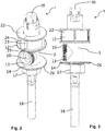
- FIG. 1 shows a sanitary valve, designated as a whole by 1, which is set up to be inserted into a fitting 2.
- the sanitary valve 1 has a valve housing 3, a main valve 4 with a movable membrane 5 and a pilot valve 6.
- the main valve 4 is set up in a known manner.
- the movable membrane 5 is made of an elastic material.
- the main valve 4 has a valve body 33 and a valve seat 34 in which the valve body 33 can be inserted. In the open position of the main valve 4, the valve body 33 is outside the valve seat 34 so that water can flow past it. In the closed position of the main valve 4, the valve body 33 is pressed into the valve seat 34 so that no water can flow off through the valve seat 34 into a drain opening 10.
- the valve body 33 has a relief opening 31 through which water can flow out into the drainage opening 10 when the relief opening 31 is open.
- the relief opening 31 can be closed by means of a valve tappet 7 of the pilot valve 6.
- a pressure builds up within a pressure chamber 28 in that water flows in via a filling opening 29 from a valve inlet 30.
- the pressure within the pressure chamber 28 pushes the valve body 33 of the main valve 4 into the valve seat 34 and closes a channel 21 of the sanitary valve 1.
- the main valve 4 is then in the closed position.
- the pilot valve 6 can be operated by means of an adjusting device part 13.
- the position of the valve tappet 7 relative to the valve body 33 can be changed by means of the adjusting device part 13.
- the position of the valve tappet 7 can be adjusted by means of an actuating element 35.
- the adjustment device part 13 preferably has a push-push mechanism which can be operated on the outside by means of the actuating element 35, in particular by means of a button. By repeatedly pressing the actuating element 35, it is possible to switch between different switching positions.
- FIG. 1 a switching position is shown in which the Sanitary valve 1, in particular the main valve 4, is in the open position.
- a hose fastening means 9 assigned to the inlet opening 8 of the valve housing 3 is formed on the valve housing 3.
- the hose fastening means 9 is in the configurations according to FIGS Figures 1-3 designed as a socket with an external thread 19.
- the hose fastening means 9 has a maximum outer diameter that is smaller than a maximum outer diameter of a contact element 14 formed on the valve housing 3.
- the contact element 14 is designed for attaching the valve housing 3 to a wall 15 of the fitting 2. In this case, the contact element 14 rests against the wall on the downstream side from the wall 15 in the flow direction of the water through the sanitary valve 1 when the valve is in the assembled state.
- the passage opening 16 has a clear inside diameter which is larger than the maximum outside diameter of the hose fastening means 9, so that the hose fastening means 9 can be introduced into the passage opening 16.
- the sanitary valve 1 has a fastening sleeve 17 with an internal thread 32 corresponding to the external thread 19 of the hose fastening means 9. This makes it possible to connect the hose 18 directly to the valve housing 3 via the fastening sleeve 17.
- the fastening sleeve 17 is connected or can be connected to the hose 18.
- the valve housing 3 forms a mouthpiece fastening means 11 at a drain opening 10 of the valve housing 3.
- the mouthpiece fastening means 11 is designed as a connecting piece with an external thread 19, to which a mouthpiece can be fastened directly or attached.
- the sanitary valve 1 In the assembly position, ie when the sanitary valve 1 is inserted into a valve receiving space 20 of the fitting 2, the sanitary valve 1 is fixed or fixable to the fitting 2 by means of the mouthpiece attached to the mouthpiece fastening means 11.
- the sanitary valve 1 cannot be accidentally slipped out or removed from the fitting 2, since the mouthpiece strikes the edge of an opening through the fitting 2 with at least one side wall.
- the opening forms an outlet opening from the fitting 2, through which the attached mouthpiece protrudes from the fitting 2.
- valve housing 3 can also form or have a jet regulator fastening means at the outlet opening 10 of the valve housing 3. It is thus also possible to fix the sanitary valve 1 on the basis of a jet regulator attached to the jet regulator fastening means.
- the mouthpiece can have a jet regulator in order to generate a water jet with desired properties.
- a jet regulator is interposed between the mouthpiece and the mouthpiece fastening means 11, for example by being insertable into the mouthpiece.
- the valve housing 3 and the adjusting device part 13 together form a channel 21 that is closed off from the outside. This can prevent water flowing through the channel 21 from coming into contact with the fitting 2.
- the sanitary valve 1 has a clamping device 12 with which the valve housing 3 and the adjusting device part 13 can be or are fixedly connected to one another in a coupling area 25 of the sanitary valve 1. In the assembly position of the sanitary valve 1, the valve housing 3 and the adjusting device part 13 are firmly connected to one another.
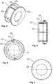
- the clamping device 12 has two identical parts. Each part 22 is designed as one half of a hollow cylinder.
- the two parts 22 of the clamping device 12 can be arranged at least partially around the valve housing 3 and the adjusting device part 13, as a result of which they can be firmly coupled to one another.
- the two parts 22 each have a coupling element 23 and a corresponding mating coupling element 24 for receiving the coupling element 23 of the respective other part 22.
- the coupling element 23 of one part 22 engages in the mating coupling element 24 of the other part 22.
- the two parts can be coupled to one another, preferably releasably coupled.
- the clamping device 12 By means of the clamping device 12, it is possible to already firmly connect the valve housing 3 and the adjustment device part 13 to one another outside the fitting 2, which allows the sanitary valve 1 to be installed more easily. Then can the sanitary valve 1 with the hose 18 attached to the valve housing 3 and the adjusting device part 13 coupled to the valve housing 3 can be inserted into the valve receiving space 20 in the fitting 2.
- the sanitary valve 1 has a plurality of fixing elements 26.
- the maximum outside diameter of the fixing elements 26, which have a circular cross-section, is dimensioned such that the sanitary valve 1 is fixed in the radial direction when it is inserted into the fitting 2, in which the fixing elements 26 rest against an inner wall 27 of the valve receiving space 20.
- the sanitary valve 1 can be inserted into an insertion opening 39 in the fitting 2 or removed from the fitting 2 exclusively in the axial direction.
- the one in the Figure 1-3 The sanitary valve 1 shown, the fixing elements 26 are formed by the clamping device 12 and by the contact element 14.
- a filter element 36 is arranged between the inlet opening 8 and the valve inlet 30, as a result of which it is possible to prevent inflowing particles from reaching the main valve 4 from the hose 18.
- the sanitary valve 1 has a securing ring 38, by means of which the valve can be fixed to the fitting 2.
- the securing ring 38 can be fastened to the edge of the insertion opening 39 of the valve receiving space 20.
- the locking ring 38 can prevent the sanitary valve 1 from slipping out or being removed from the insertion opening 39 in the axial direction.
- the securing ring 38 is preferably designed as a snap ring which, when inserted, engages in a recess, in particular designed as a groove, on the fitting 2 and thereby axially fixes the sanitary valve 1.
- a snap ring enables a particularly inexpensive, yet stable, axial fixing.
Landscapes
- Engineering & Computer Science (AREA)
- General Engineering & Computer Science (AREA)
- Mechanical Engineering (AREA)
- Public Health (AREA)
- Life Sciences & Earth Sciences (AREA)
- Hydrology & Water Resources (AREA)
- Health & Medical Sciences (AREA)
- Water Supply & Treatment (AREA)
- Fluid-Driven Valves (AREA)
- Valve Housings (AREA)
- Quick-Acting Or Multi-Walled Pipe Joints (AREA)
- Safety Valves (AREA)
- Bidet-Like Cleaning Device And Other Flush Toilet Accessories (AREA)
Claims (14)
- Vanne sanitaire (1) destinée à être utilisée dans un robinet (2), avec un corps de vanne (3), une vanne principale (4) qui possède une membrane mobile (5), et une vanne pilote (6) avec laquelle la vanne principale (4) peut être commandée, dans laquelle une position de la membrane (5) peut être prédéfinie par une position d'un poussoir de vanne (7) de la vanne pilote (6), la vanne sanitaire (1) possédant un dispositif de serrage (12) avec lequel le corps de vanne (3) et un élément de dispositif de réglage (13) peuvent être fixés ou sont fixés ensemble, caractérisée en ce que le dispositif de serrage (12) est constitué de deux parties (22) qui présentent chacune un élément d'accouplement (23) et un élément d'accouplement opposé correspondant (24) pour recevoir l'élément d'accouplement (23) de l'autre partie (22), de sorte que les deux parties (22) peuvent être accouplées l'une avec l'autre.
- Vanne sanitaire (1) selon la revendication 1, caractérisée en ce que le dispositif de serrage (12) présente deux parties (22) pouvant être reliées l'une avec l'autre qui forment en position de montage un cylindre creux qui entoure le corps de vanne (3) et l'élément de dispositif de réglage (13) au moins dans une zone d'accouplement (25) et les relie ainsi de manière fixe.
- Vanne sanitaire (1) selon une des revendications précédentes, caractérisée en ce qu'un moyen de fixation de tuyau (9) possède un diamètre extérieur maximum qui est inférieur à un diamètre extérieur maximum d'un élément d'application (14) formé ou monté sur le corps de vanne (3) pour appliquer le corps de vanne (3) contre une ouverture de passage (16) dans une paroi (15) du robinet (2), dans laquelle l'ouverture de passage (16) possède un diamètre intérieur libre qui est supérieur au diamètre extérieur maximum du moyen de fixation de tuyau (9).
- Vanne sanitaire (1) selon la revendication 3, caractérisée en ce que le moyen de fixation de tuyau (9) présente un filetage extérieur (19) pour le raccordement d'un filetage intérieur correspondant (32), un particulier d'un filetage intérieur correspondant (32) d'un manchon de fixation (17) de la vanne sanitaire (1) qui peut être reliée ou est reliée avec un tuyau (18) ou que le moyen de fixation de tuyau (9) présente un filetage intérieur pour le raccordement d'un filetage extérieur correspondant (19), un particulier d'un filetage extérieur correspondant (19) d'un manchon de fixation (17) de la vanne sanitaire (1) qui peut être reliée ou est reliée avec un tuyau (18) ou que le moyen de fixation de tuyau (9) est configuré comme une plaque de retenue avec un réceptacle de tuyau.
- Vanne sanitaire (1) selon une des revendications précédentes, caractérisée en ce que cette vanne sanitaire (1) possède un embout qui peut être fixé ou est fixé directement sur le moyen de fixation d'embout (11), la vanne sanitaire (1) insérée dans un espace de réception de vanne (20) du robinet (2) pouvant être fixée ou étant fixée sur le robinet (2) au moyen de l'embout fixé sur le moyen de fixation d'embout (11), et/ou que la vanne sanitaire (1) possède une bague de retenue (38), en particulier une bague élastique, par laquelle la vanne peut être fixée sur le robinet (2).
- Vanne sanitaire (1) selon la revendication 5, caractérisée en ce que cette vanne sanitaire (1) possède un régulateur de jet qui peut être fixé ou est fixé directement sur le moyen de fixation de régulateur de jet, la vanne sanitaire (1) insérée dans un espace de réception (20) du robinet (2) pouvant être fixée sur le robinet (2) au moyen du régulateur de jet fixé sur le moyen de fixation de régulateur de jet et/ou qu'un embout présente un régulateur de jet ou qu'un régulateur de jet est disposé entre un ou l'embout et l'ouverture d'évacuation (10).
- Vanne sanitaire (1) selon la revendication 6, caractérisée en ce qu'un embout possède un filetage intérieur et le corps de vanne (3) un filetage extérieur (19) correspondant au niveau de l'ouverture d'évacuation (10) ou qu'un ou l'embout possède un filetage extérieur (19) et le corps de vanne (3) un filetage intérieur (32) correspondant au niveau de l'ouverture d'évacuation, et/ou que le régulateur de jet possède un filetage intérieur et le corps de vanne (3) un filetage extérieur (19) correspondant au niveau de l'ouverture d'évacuation (10) ou que le régulateur de jet possède un filetage extérieur (19) et le corps de vanne (3) un filetage intérieur (32) correspondant au niveau de l'ouverture d'évacuation.
- Vanne sanitaire (1) selon une des revendications précédentes, caractérisée en ce qu'à travers le corps de vanne (3) et l'élément de dispositif de réglage (13) sont formées une canalisation (21) fermée du côté du robinet (2) et/ou une chambre de pression (28) fermée du côté du robinet (2) par le biais desquelles un contact entre un liquide s'écoulant à travers la vanne sanitaire (1) et le robinet (2) est possible.
- Vanne sanitaire (1) selon une des revendications précédentes, caractérisée en ce que le dispositif de serrage (12) est constitué de deux parties (22) identiques qui présentent chacune un élément d'accouplement (23) et un élément d'accouplement opposé correspondant (24) pour recevoir l'élément d'accouplement (23) de l'autre partie (22), de sorte que les deux parties (22) peuvent être accouplées l'une avec l'autre, de préférence de façon amovible.
- Vanne sanitaire (1) selon une des revendications précédentes, caractérisée en ce que le dispositif de serrage (12) présente de deux parties (22) pouvant être reliées l'une avec l'autre, de préférence de façon amovible, qui forment en position de montage un cylindre creux qui entoure le corps de vanne (3) et l'élément de dispositif de réglage (13) au moins dans une zone d'accouplement (25) et les relie ainsi de manière fixe, de sorte que, grâce au dispositif de serrage (12), une liaison fixe du corps de vanne (3) et de l'élément de dispositif de réglage (13) hors du robinet (2) est possible.
- Vanne sanitaire (1) selon une des revendications précédentes, caractérisée en ce que cette vanne sanitaire (1) présente au moins un élément de fixation (26) dont le diamètre extérieur maximum est conçu de telle sorte que la vanne sanitaire (1), lorsqu'elle est insérée dans le robinet (2), est fixée en direction radiale, de sorte que l'au moins un élément de fixation (26) est appliqué sur une paroi intérieure (27) d'un ou de l'espace de réception de vanne (20) et que la vanne sanitaire (1) ne peut donc être insérée dans le robinet (2) ou extraite du robinet (2) qu'en direction axiale, l'élément de fixation (26) ou les éléments de fixation (26) étant de préférence constitué(s) par le dispositif de serrage (12) et/ou l'élément d'application (14).
- Vanne sanitaire (1) selon la revendication 8, caractérisée en ce que la membrane mobile (5) obture la chambre de pression (28) qui est configurée entre le corps de vanne (3) et l'élément de dispositif de réglage (13), que la chambre de pression (28) peut être remplie par une ouverture de remplissage (29) avec un liquide affluant par une entrée de vanne (30), la chambre de pression (28) étant aménagée de sorte qu'une pression peut s'accroitre à l'intérieur de la chambre de pression (28) quand une ouverture de décharge est fermée.
- Vanne sanitaire (1) selon une des revendications précédentes, caractérisée en ce que sur le corps de vanne (3) est constitué un moyen de fixation de tuyau (9) associé à une ouverture d'admission (8) du corps de vanne (3), de sorte qu'un tuyau (8) peut être raccordé directement au corps de vanne (3).
- Vanne sanitaire (1) selon la revendication 5, caractérisée en ce que sur le corps de vanne (3) sont constitués un moyen de fixation d'embout (11) et/ou un moyen de fixation de régulateur de jet associés à une ouverture d'évacuation (10) du corps de vanne (3).
Priority Applications (1)
| Application Number | Priority Date | Filing Date | Title |
|---|---|---|---|
| EP20171601.6A EP3730705B1 (fr) | 2017-05-26 | 2018-02-20 | Soupape sanitaire |
Applications Claiming Priority (2)
| Application Number | Priority Date | Filing Date | Title |
|---|---|---|---|
| DE202017103194.2U DE202017103194U1 (de) | 2017-05-26 | 2017-05-26 | Sanitärventil |
| PCT/EP2018/054150 WO2018215098A1 (fr) | 2017-05-26 | 2018-02-20 | Valve de plomberie comprenant une membrane |
Related Child Applications (2)
| Application Number | Title | Priority Date | Filing Date |
|---|---|---|---|
| EP20171601.6A Division EP3730705B1 (fr) | 2017-05-26 | 2018-02-20 | Soupape sanitaire |
| EP20171601.6A Division-Into EP3730705B1 (fr) | 2017-05-26 | 2018-02-20 | Soupape sanitaire |
Publications (2)
| Publication Number | Publication Date |
|---|---|
| EP3631100A1 EP3631100A1 (fr) | 2020-04-08 |
| EP3631100B1 true EP3631100B1 (fr) | 2021-12-01 |
Family
ID=61249651
Family Applications (2)
| Application Number | Title | Priority Date | Filing Date |
|---|---|---|---|
| EP18706264.1A Active EP3631100B1 (fr) | 2017-05-26 | 2018-02-20 | Valve de plomberie comprenant une membrane |
| EP20171601.6A Active EP3730705B1 (fr) | 2017-05-26 | 2018-02-20 | Soupape sanitaire |
Family Applications After (1)
| Application Number | Title | Priority Date | Filing Date |
|---|---|---|---|
| EP20171601.6A Active EP3730705B1 (fr) | 2017-05-26 | 2018-02-20 | Soupape sanitaire |
Country Status (5)
| Country | Link |
|---|---|
| US (1) | US11739858B2 (fr) |
| EP (2) | EP3631100B1 (fr) |
| CN (2) | CN112031102B (fr) |
| DE (1) | DE202017103194U1 (fr) |
| WO (1) | WO2018215098A1 (fr) |
Families Citing this family (3)
| Publication number | Priority date | Publication date | Assignee | Title |
|---|---|---|---|---|
| DE202017103194U1 (de) | 2017-05-26 | 2018-08-28 | Neoperl Gmbh | Sanitärventil |
| CN111395486B (zh) * | 2020-03-25 | 2021-05-04 | 艾迪机器(杭州)有限公司 | 一种污水收集智控界面阀系统 |
| CN111395485B (zh) * | 2020-03-25 | 2021-05-04 | 厚力德机器(杭州)有限公司 | 一种污水收集智控界面阀及变控方法 |
Citations (35)
| Publication number | Priority date | Publication date | Assignee | Title |
|---|---|---|---|---|
| GB1058546A (en) | 1963-05-06 | 1967-02-15 | Grinnell Corp | Improvements in or relating to valves for controlling fluid flow |
| US4503887A (en) | 1982-01-19 | 1985-03-12 | Automatic Switch Company | Pilot-operated dual flow rate valve |
| EP0318743A1 (fr) | 1987-12-02 | 1989-06-07 | Ganser-Hydromag | Injecteur de combustible commandé électroniquement |
| US5180138A (en) | 1991-02-08 | 1993-01-19 | Firma A.U.K. Muller Gmbh & Co. Kg | Solenoid controlled servo valve |
| WO1996014479A1 (fr) | 1994-11-04 | 1996-05-17 | Frost Douglas R D | Vanne de vidange |
| GB2304175A (en) | 1995-08-12 | 1997-03-12 | Pacson Ltd | Rising stem valve |
| US5722367A (en) | 1995-10-10 | 1998-03-03 | Walbro Corporation | Engine idle speed air control |
| US5979482A (en) | 1998-04-02 | 1999-11-09 | Hunter Industries, Inc. | Removable captive plunger with contamination protection |
| US6161570A (en) | 1999-06-01 | 2000-12-19 | Tyco Flow Control, Inc. | Pilot-operated relief valve |
| WO2003056222A1 (fr) | 2001-12-28 | 2003-07-10 | Ode Officine Di Esino Lario S.R.L. | Vanne electromagnetique pour appareils sanitaires |
| WO2004023009A1 (fr) | 2002-08-14 | 2004-03-18 | Tuchenhagen Gmbh | Systeme de commande pour soupapes a double siege |
| DE102004037613A1 (de) | 2003-08-08 | 2005-03-03 | Smc Corp. | Pilot-gesteuertes elektromagnetisches Ventil |
| DE19654284B4 (de) | 1995-12-27 | 2005-07-21 | Elbi International S.P.A. | Hydraulikventil mit Magnetsteuerventil, insbesondere für Reinigungsmaschinen |
| DE102004058252A1 (de) | 2004-08-14 | 2006-02-23 | Protechna S.A. | Überwurfmutter aus Kunststoff |
| US20060108550A1 (en) | 2002-07-29 | 2006-05-25 | Jens Burmester | Device for actuating double seat valves |
| US20060163513A1 (en) | 2004-11-30 | 2006-07-27 | Keihin Corporation | Solenoid-operated cutoff valve for use with fuel cells |
| WO2008131246A1 (fr) | 2007-04-20 | 2008-10-30 | Fisher Controls International Llc | Siège secondaire pour régulateur de gaz |
| US20110005611A1 (en) | 2008-03-20 | 2011-01-13 | Jens Burmester | Double seat valve capable of cleaning the seat and having a cleaning device for a housing penetration |
| DE102010030298A1 (de) | 2010-06-21 | 2011-12-22 | Krones Aktiengesellschaft | Mehrteiliger Ventilteller |
| US20120012207A1 (en) | 2009-12-16 | 2012-01-19 | Weigen Chen | Automatic water flushing control device and its faucet |
| EP2489793A1 (fr) | 2011-02-16 | 2012-08-22 | Geberit International AG | Agencement de chasse d'eau |
| US8272083B1 (en) | 2011-04-20 | 2012-09-25 | Liston Thomas D | System and method for faucet installations |
| WO2012149612A1 (fr) | 2011-05-02 | 2012-11-08 | Dispack-Projects Nv | Fixation d'une garniture sur un récipient |
| DE102011050617A1 (de) | 2011-05-24 | 2012-12-13 | A. u. K. Müller GmbH & Co KG | Ventil |
| WO2013079190A1 (fr) | 2011-12-03 | 2013-06-06 | Gea Tuchenhagen Gmbh | Entraînement de commande d'une vanne à double siège |
| US20130167953A1 (en) | 2010-03-30 | 2013-07-04 | Toto Ltd. | Faucet device |
| DE102012221047A1 (de) | 2012-11-19 | 2014-05-22 | Hansgrohe Se | Ventiloberteil für eine Sanitärarmatur |
| US20150144822A1 (en) | 2012-09-27 | 2015-05-28 | Kabushiki Kaisha Fujikin | Diaphragm Valve |
| US20150267385A1 (en) | 2014-03-21 | 2015-09-24 | Ming-Shuan Lin | Sensor Faucet |
| FR3022605A1 (fr) | 2014-06-20 | 2015-12-25 | Mmt Sa | Vanne motorisee et procedure d'assemblage d'un moyen de fixation |
| EP2980463A1 (fr) | 2013-03-28 | 2016-02-03 | Zhejiang Sanhua Co., Ltd. | Électrovanne bidirectionnelle |
| WO2016106314A1 (fr) | 2014-12-22 | 2016-06-30 | Eaton Corporation | Soupape en ligne à deux étages |
| CN205689872U (zh) | 2016-06-23 | 2016-11-16 | 浙江科博电器有限公司 | 一种应用于电磁阀的阀杆调位装置及一种电磁阀 |
| CN206130278U (zh) * | 2016-02-22 | 2017-04-26 | 纽珀有限公司 | 阀致动装置 |
| DE202016001106U1 (de) | 2016-02-22 | 2017-05-23 | Neoperl Gmbh | Ventilbetätigungsvorrichtung |
Family Cites Families (53)
| Publication number | Priority date | Publication date | Assignee | Title |
|---|---|---|---|---|
| DE2533527A1 (de) | 1975-07-26 | 1977-01-27 | Dalferth Gotthilf R | Vorrichtung zur abgabe von fluessigkeiten ueber einen auslauf |
| DE3120210A1 (de) | 1981-05-21 | 1982-12-09 | Friedrich Grohe Armaturenfabrik Gmbh & Co, 5870 Hemer | Wasserzapfarmatur |
| GB2103391B (en) * | 1981-07-31 | 1986-02-19 | Peglers Ltd | Servo operated fluid flow taps and valves |
| US4520516A (en) | 1983-09-23 | 1985-06-04 | Parsons Natan E | Ultrasonic flow-control system |
| US4839039B2 (en) | 1986-02-28 | 1998-12-29 | Recurrent Solutions Ltd | Automatic flow-control device |
| EP0386212A4 (en) | 1988-09-14 | 1992-03-11 | Chang Hwan Lee | Automatic mixing faucet |
| US4915347A (en) * | 1989-05-18 | 1990-04-10 | Kohler Co. | Solenoid operated faucet |
| CH681385A5 (fr) | 1989-11-16 | 1993-03-15 | Karrer Weber & Cie Ag | |
| DE3938533A1 (de) | 1989-11-21 | 1991-05-23 | Rainer M Lutz | Wasserauslaufarmatur |
| IL105133A0 (en) | 1993-03-22 | 1993-07-08 | Madgal Glil Yam | Electronically operated faucet including sensing means |
| DE4420332A1 (de) | 1994-06-10 | 1995-12-14 | Grohe Armaturen Friedrich | Wasserarmatur |
| DE4420330A1 (de) | 1994-06-10 | 1995-12-14 | Grohe Armaturen Friedrich | Wasserarmatur mit elektrischer Steuerung |
| DE4431127C2 (de) | 1994-09-01 | 2001-02-15 | Hansgrohe Ag | Sanitärventil mit einem Magnetventil |
| DE29611323U1 (de) | 1996-06-28 | 1996-09-05 | Ymos Ag Ind Produkte | Einhebelmischer |
| DE19651132C2 (de) | 1996-12-10 | 2000-11-23 | Ideal Standard | Sanitäre Näherungsarmatur |
| US5911240A (en) * | 1997-10-27 | 1999-06-15 | Kohler Co. | Self-closing solenoid operated faucet |
| US6000674A (en) * | 1998-11-13 | 1999-12-14 | Cheng; Hong-Ming | Reliable flush valve |
| JP2002048253A (ja) | 2000-08-02 | 2002-02-15 | Inax Corp | ダイヤフラム弁 |
| US6671898B1 (en) | 2000-08-23 | 2004-01-06 | Geberit Technik Ag | Water fitting |
| JP3687734B2 (ja) | 2000-08-25 | 2005-08-24 | テクノエクセル株式会社 | 手動並びに電磁式給水弁装置 |
| US6382586B1 (en) | 2000-12-14 | 2002-05-07 | Sloan Valve Company | Flush valve assembly with flex tube |
| CA2469182C (fr) | 2001-12-04 | 2014-06-03 | Arichell Technologies, Inc. | Robinets electroniques concus pour un fonctionnement a long terme |
| WO2004020886A1 (fr) * | 2002-08-30 | 2004-03-11 | Toto Ltd. | Vanne d'ouverture et de fermeture |
| JP3743006B2 (ja) | 2004-06-09 | 2006-02-08 | 東陶機器株式会社 | 開閉弁装置及びそれを備えた水栓装置 |
| US20090146090A1 (en) * | 2005-07-12 | 2009-06-11 | Inax Corporation | Pilot Type Water Discharging/Stopping and Flow Regulating Valve Device |
| CN1924415A (zh) * | 2005-08-30 | 2007-03-07 | 和成欣业股份有限公司 | 水龙头结构 |
| US7445024B2 (en) * | 2006-01-09 | 2008-11-04 | Speakman Company | Above deck modular faucet assembly |
| CN200972002Y (zh) * | 2006-06-23 | 2007-11-07 | 欧阳华安 | 水龙头 |
| DE602008000696D1 (de) | 2007-07-26 | 2010-04-08 | Brother Ind Ltd | Bildaufzeichnungsvorrichtung |
| JP2009074343A (ja) | 2007-09-21 | 2009-04-09 | San-Ei Faucet Mfg Co Ltd | 水栓の吐水部構造 |
| JP4264845B1 (ja) | 2008-05-27 | 2009-05-20 | Toto株式会社 | 水栓用発電機 |
| CN201237001Y (zh) * | 2008-08-15 | 2009-05-13 | 李仁波 | 水龙头阀体 |
| JP5453873B2 (ja) | 2009-03-27 | 2014-03-26 | Toto株式会社 | 自動水栓 |
| CN201475339U (zh) | 2009-07-11 | 2010-05-19 | 阳雷鸣 | 阀芯直开启无泄漏水嘴 |
| DE102010009215A1 (de) | 2010-02-25 | 2011-08-25 | Guzman, Cristobal, 74363 | Strömungsregler für Flüssigkeiten mit Energieversorgung über die Strömung |
| CN201779309U (zh) * | 2010-04-26 | 2011-03-30 | 陈绍基 | 快速开关式调温水龙头 |
| JP5626516B2 (ja) | 2010-09-09 | 2014-11-19 | Toto株式会社 | 吐水装置 |
| US9695579B2 (en) * | 2011-03-15 | 2017-07-04 | Sloan Valve Company | Automatic faucets |
| DE202011052262U1 (de) | 2011-12-12 | 2012-02-16 | Winlenk Automation Inc. | Flüssigkeitsausgabeanordnung |
| JP6052491B2 (ja) | 2012-08-24 | 2016-12-27 | Toto株式会社 | 自動水栓 |
| DE102012221043A1 (de) * | 2012-11-19 | 2014-05-22 | Hansgrohe Se | Sanitärventil |
| DE202013101071U1 (de) | 2013-03-12 | 2014-08-06 | Wwb Sweden Ab | Küchenarmatur |
| US10184230B2 (en) | 2013-06-08 | 2019-01-22 | Sidus Technologies, Inc. | Mechanical touch faucet |
| CN203656296U (zh) | 2013-12-31 | 2014-06-18 | 厦门松霖科技有限公司 | 一种按压开闭调流量阀 |
| CN105042153B (zh) | 2014-04-23 | 2018-05-25 | 柯勒米拉有限公司 | 用于对放水装置进行编程和控制的系统和方法 |
| US9920508B2 (en) | 2014-06-09 | 2018-03-20 | Chung-Chia Chen | Touch-free faucets and sensors |
| CN104089050B (zh) * | 2014-07-02 | 2016-11-02 | 路达(厦门)工业有限公司 | 水龙头组件及其制造方法 |
| USD765820S1 (en) | 2015-08-12 | 2016-09-06 | Evan Schneider | Electronic showerhead device |
| DE102015114062A1 (de) * | 2015-08-25 | 2017-03-02 | Schell Gmbh & Co. Kg | Hydraulisch gesteuerte Unterputz-WC-Spülarmatur |
| US10227760B2 (en) | 2016-03-08 | 2019-03-12 | Flowe Green, LLC | System and method for a smart faucet |
| DE102016108045A1 (de) | 2016-04-29 | 2017-11-02 | A. u. K. Müller GmbH & Co. KG | Armaturauslass und Armatur |
| CN106051208B (zh) * | 2016-07-27 | 2019-11-29 | 路达(厦门)工业有限公司 | 切换阀单元、流体开关和流体开关的套件 |
| DE202017103194U1 (de) | 2017-05-26 | 2018-08-28 | Neoperl Gmbh | Sanitärventil |
-
2017
- 2017-05-26 DE DE202017103194.2U patent/DE202017103194U1/de active Active
-
2018
- 2018-02-20 WO PCT/EP2018/054150 patent/WO2018215098A1/fr active Application Filing
- 2018-02-20 US US16/609,317 patent/US11739858B2/en active Active
- 2018-02-20 EP EP18706264.1A patent/EP3631100B1/fr active Active
- 2018-02-20 CN CN202011094676.3A patent/CN112031102B/zh active Active
- 2018-02-20 EP EP20171601.6A patent/EP3730705B1/fr active Active
- 2018-02-20 CN CN201880030489.3A patent/CN110637133B/zh active Active
Patent Citations (35)
| Publication number | Priority date | Publication date | Assignee | Title |
|---|---|---|---|---|
| GB1058546A (en) | 1963-05-06 | 1967-02-15 | Grinnell Corp | Improvements in or relating to valves for controlling fluid flow |
| US4503887A (en) | 1982-01-19 | 1985-03-12 | Automatic Switch Company | Pilot-operated dual flow rate valve |
| EP0318743A1 (fr) | 1987-12-02 | 1989-06-07 | Ganser-Hydromag | Injecteur de combustible commandé électroniquement |
| US5180138A (en) | 1991-02-08 | 1993-01-19 | Firma A.U.K. Muller Gmbh & Co. Kg | Solenoid controlled servo valve |
| WO1996014479A1 (fr) | 1994-11-04 | 1996-05-17 | Frost Douglas R D | Vanne de vidange |
| GB2304175A (en) | 1995-08-12 | 1997-03-12 | Pacson Ltd | Rising stem valve |
| US5722367A (en) | 1995-10-10 | 1998-03-03 | Walbro Corporation | Engine idle speed air control |
| DE19654284B4 (de) | 1995-12-27 | 2005-07-21 | Elbi International S.P.A. | Hydraulikventil mit Magnetsteuerventil, insbesondere für Reinigungsmaschinen |
| US5979482A (en) | 1998-04-02 | 1999-11-09 | Hunter Industries, Inc. | Removable captive plunger with contamination protection |
| US6161570A (en) | 1999-06-01 | 2000-12-19 | Tyco Flow Control, Inc. | Pilot-operated relief valve |
| WO2003056222A1 (fr) | 2001-12-28 | 2003-07-10 | Ode Officine Di Esino Lario S.R.L. | Vanne electromagnetique pour appareils sanitaires |
| US20060108550A1 (en) | 2002-07-29 | 2006-05-25 | Jens Burmester | Device for actuating double seat valves |
| WO2004023009A1 (fr) | 2002-08-14 | 2004-03-18 | Tuchenhagen Gmbh | Systeme de commande pour soupapes a double siege |
| DE102004037613A1 (de) | 2003-08-08 | 2005-03-03 | Smc Corp. | Pilot-gesteuertes elektromagnetisches Ventil |
| DE102004058252A1 (de) | 2004-08-14 | 2006-02-23 | Protechna S.A. | Überwurfmutter aus Kunststoff |
| US20060163513A1 (en) | 2004-11-30 | 2006-07-27 | Keihin Corporation | Solenoid-operated cutoff valve for use with fuel cells |
| WO2008131246A1 (fr) | 2007-04-20 | 2008-10-30 | Fisher Controls International Llc | Siège secondaire pour régulateur de gaz |
| US20110005611A1 (en) | 2008-03-20 | 2011-01-13 | Jens Burmester | Double seat valve capable of cleaning the seat and having a cleaning device for a housing penetration |
| US20120012207A1 (en) | 2009-12-16 | 2012-01-19 | Weigen Chen | Automatic water flushing control device and its faucet |
| US20130167953A1 (en) | 2010-03-30 | 2013-07-04 | Toto Ltd. | Faucet device |
| DE102010030298A1 (de) | 2010-06-21 | 2011-12-22 | Krones Aktiengesellschaft | Mehrteiliger Ventilteller |
| EP2489793A1 (fr) | 2011-02-16 | 2012-08-22 | Geberit International AG | Agencement de chasse d'eau |
| US8272083B1 (en) | 2011-04-20 | 2012-09-25 | Liston Thomas D | System and method for faucet installations |
| WO2012149612A1 (fr) | 2011-05-02 | 2012-11-08 | Dispack-Projects Nv | Fixation d'une garniture sur un récipient |
| DE102011050617A1 (de) | 2011-05-24 | 2012-12-13 | A. u. K. Müller GmbH & Co KG | Ventil |
| WO2013079190A1 (fr) | 2011-12-03 | 2013-06-06 | Gea Tuchenhagen Gmbh | Entraînement de commande d'une vanne à double siège |
| US20150144822A1 (en) | 2012-09-27 | 2015-05-28 | Kabushiki Kaisha Fujikin | Diaphragm Valve |
| DE102012221047A1 (de) | 2012-11-19 | 2014-05-22 | Hansgrohe Se | Ventiloberteil für eine Sanitärarmatur |
| EP2980463A1 (fr) | 2013-03-28 | 2016-02-03 | Zhejiang Sanhua Co., Ltd. | Électrovanne bidirectionnelle |
| US20150267385A1 (en) | 2014-03-21 | 2015-09-24 | Ming-Shuan Lin | Sensor Faucet |
| FR3022605A1 (fr) | 2014-06-20 | 2015-12-25 | Mmt Sa | Vanne motorisee et procedure d'assemblage d'un moyen de fixation |
| WO2016106314A1 (fr) | 2014-12-22 | 2016-06-30 | Eaton Corporation | Soupape en ligne à deux étages |
| CN206130278U (zh) * | 2016-02-22 | 2017-04-26 | 纽珀有限公司 | 阀致动装置 |
| DE202016001106U1 (de) | 2016-02-22 | 2017-05-23 | Neoperl Gmbh | Ventilbetätigungsvorrichtung |
| CN205689872U (zh) | 2016-06-23 | 2016-11-16 | 浙江科博电器有限公司 | 一种应用于电磁阀的阀杆调位装置及一种电磁阀 |
Also Published As
| Publication number | Publication date |
|---|---|
| EP3730705C0 (fr) | 2024-02-14 |
| US11739858B2 (en) | 2023-08-29 |
| CN112031102B (zh) | 2022-12-27 |
| EP3730705B1 (fr) | 2024-02-14 |
| BR112019020874A2 (pt) | 2020-04-28 |
| CN110637133A (zh) | 2019-12-31 |
| EP3730705A1 (fr) | 2020-10-28 |
| DE202017103194U1 (de) | 2018-08-28 |
| CN112031102A (zh) | 2020-12-04 |
| CN110637133B (zh) | 2021-05-28 |
| US20210301511A1 (en) | 2021-09-30 |
| EP3631100A1 (fr) | 2020-04-08 |
| WO2018215098A1 (fr) | 2018-11-29 |
Similar Documents
| Publication | Publication Date | Title |
|---|---|---|
| EP1918465B1 (fr) | Régulateur jet comprenant une codification en couleur du débit | |
| EP3513009B1 (fr) | Dispositif d'evacuation sanitaire et distributeur d'eau | |
| DE3100037C2 (fr) | ||
| EP3631100B1 (fr) | Valve de plomberie comprenant une membrane | |
| WO2007042100A1 (fr) | Piece de montage pour sanitaire | |
| EP2385282B1 (fr) | Agencement de soupape doté d'un élément de base et d'un élément d'insertion | |
| EP1707692B1 (fr) | Robinet pourvu d'un bec téléscopique | |
| WO2002042676A1 (fr) | Dispositif de raccord d'une conduite de fluide | |
| EP0937926A2 (fr) | Vanne de sous pression | |
| EP3551808B1 (fr) | Vanne d'eau sous pression | |
| DE2712062C2 (de) | Ventil | |
| EP2047110A1 (fr) | Dispositif technique fluidique | |
| DE102005052385B4 (de) | Druckminderer | |
| EP1770225A2 (fr) | Raccordement pour tuyaux sanitaires avec un joint annulaire maintenu en place par liaison de forme | |
| DE102007025290B4 (de) | Sanitäre Auslaufarmatur | |
| DE102008015869A1 (de) | Strahlregler | |
| EP2530365B2 (fr) | Garniture de soupape pour une armature sanitaire | |
| DE102004053576B3 (de) | Schaltknauf und Schalthebel mit einem solchen Schaltknauf | |
| DE202007002904U1 (de) | Durchflussmengenregler | |
| EP2481856B1 (fr) | Unité de soupape de remplissage | |
| EP3679282A1 (fr) | Ensemble soupape | |
| DE102017111533A1 (de) | Sanitärventil | |
| DE19900472C1 (de) | Ventil zum Entlüften, Befüllen oder Entleeren insbesondere für Heizkörper oder Heizanlagen | |
| DE19926043B4 (de) | Verdrehsicherungseinrichtung | |
| DE102006054645B4 (de) | Verbindungsvorrichtung für ein Fluidsystem |
Legal Events
| Date | Code | Title | Description |
|---|---|---|---|
| STAA | Information on the status of an ep patent application or granted ep patent |
Free format text: STATUS: UNKNOWN |
|
| STAA | Information on the status of an ep patent application or granted ep patent |
Free format text: STATUS: THE INTERNATIONAL PUBLICATION HAS BEEN MADE |
|
| PUAI | Public reference made under article 153(3) epc to a published international application that has entered the european phase |
Free format text: ORIGINAL CODE: 0009012 |
|
| STAA | Information on the status of an ep patent application or granted ep patent |
Free format text: STATUS: REQUEST FOR EXAMINATION WAS MADE |
|
| 17P | Request for examination filed |
Effective date: 20200102 |
|
| AK | Designated contracting states |
Kind code of ref document: A1 Designated state(s): AL AT BE BG CH CY CZ DE DK EE ES FI FR GB GR HR HU IE IS IT LI LT LU LV MC MK MT NL NO PL PT RO RS SE SI SK SM TR |
|
| AX | Request for extension of the european patent |
Extension state: BA ME |
|
| DAV | Request for validation of the european patent (deleted) | ||
| DAX | Request for extension of the european patent (deleted) | ||
| STAA | Information on the status of an ep patent application or granted ep patent |
Free format text: STATUS: EXAMINATION IS IN PROGRESS |
|
| STAA | Information on the status of an ep patent application or granted ep patent |
Free format text: STATUS: EXAMINATION IS IN PROGRESS |
|
| 17Q | First examination report despatched |
Effective date: 20201201 |
|
| TPAC | Observations filed by third parties |
Free format text: ORIGINAL CODE: EPIDOSNTIPA |
|
| GRAP | Despatch of communication of intention to grant a patent |
Free format text: ORIGINAL CODE: EPIDOSNIGR1 |
|
| STAA | Information on the status of an ep patent application or granted ep patent |
Free format text: STATUS: GRANT OF PATENT IS INTENDED |
|
| INTG | Intention to grant announced |
Effective date: 20210714 |
|
| GRAS | Grant fee paid |
Free format text: ORIGINAL CODE: EPIDOSNIGR3 |
|
| GRAA | (expected) grant |
Free format text: ORIGINAL CODE: 0009210 |
|
| STAA | Information on the status of an ep patent application or granted ep patent |
Free format text: STATUS: THE PATENT HAS BEEN GRANTED |
|
| AK | Designated contracting states |
Kind code of ref document: B1 Designated state(s): AL AT BE BG CH CY CZ DE DK EE ES FI FR GB GR HR HU IE IS IT LI LT LU LV MC MK MT NL NO PL PT RO RS SE SI SK SM TR |
|
| REG | Reference to a national code |
Ref country code: GB Ref legal event code: FG4D Free format text: NOT ENGLISH |
|
| REG | Reference to a national code |
Ref country code: AT Ref legal event code: REF Ref document number: 1451885 Country of ref document: AT Kind code of ref document: T Effective date: 20211215 Ref country code: CH Ref legal event code: EP |
|
| REG | Reference to a national code |
Ref country code: DE Ref legal event code: R096 Ref document number: 502018008033 Country of ref document: DE |
|
| REG | Reference to a national code |
Ref country code: IE Ref legal event code: FG4D Free format text: LANGUAGE OF EP DOCUMENT: GERMAN |
|
| REG | Reference to a national code |
Ref country code: LT Ref legal event code: MG9D |
|
| REG | Reference to a national code |
Ref country code: NL Ref legal event code: MP Effective date: 20211201 |
|
| PG25 | Lapsed in a contracting state [announced via postgrant information from national office to epo] |
Ref country code: RS Free format text: LAPSE BECAUSE OF FAILURE TO SUBMIT A TRANSLATION OF THE DESCRIPTION OR TO PAY THE FEE WITHIN THE PRESCRIBED TIME-LIMIT Effective date: 20211201 Ref country code: LT Free format text: LAPSE BECAUSE OF FAILURE TO SUBMIT A TRANSLATION OF THE DESCRIPTION OR TO PAY THE FEE WITHIN THE PRESCRIBED TIME-LIMIT Effective date: 20211201 Ref country code: FI Free format text: LAPSE BECAUSE OF FAILURE TO SUBMIT A TRANSLATION OF THE DESCRIPTION OR TO PAY THE FEE WITHIN THE PRESCRIBED TIME-LIMIT Effective date: 20211201 Ref country code: BG Free format text: LAPSE BECAUSE OF FAILURE TO SUBMIT A TRANSLATION OF THE DESCRIPTION OR TO PAY THE FEE WITHIN THE PRESCRIBED TIME-LIMIT Effective date: 20220301 |
|
| PG25 | Lapsed in a contracting state [announced via postgrant information from national office to epo] |
Ref country code: SE Free format text: LAPSE BECAUSE OF FAILURE TO SUBMIT A TRANSLATION OF THE DESCRIPTION OR TO PAY THE FEE WITHIN THE PRESCRIBED TIME-LIMIT Effective date: 20211201 Ref country code: PL Free format text: LAPSE BECAUSE OF FAILURE TO SUBMIT A TRANSLATION OF THE DESCRIPTION OR TO PAY THE FEE WITHIN THE PRESCRIBED TIME-LIMIT Effective date: 20211201 Ref country code: NO Free format text: LAPSE BECAUSE OF FAILURE TO SUBMIT A TRANSLATION OF THE DESCRIPTION OR TO PAY THE FEE WITHIN THE PRESCRIBED TIME-LIMIT Effective date: 20220301 Ref country code: LV Free format text: LAPSE BECAUSE OF FAILURE TO SUBMIT A TRANSLATION OF THE DESCRIPTION OR TO PAY THE FEE WITHIN THE PRESCRIBED TIME-LIMIT Effective date: 20211201 Ref country code: HR Free format text: LAPSE BECAUSE OF FAILURE TO SUBMIT A TRANSLATION OF THE DESCRIPTION OR TO PAY THE FEE WITHIN THE PRESCRIBED TIME-LIMIT Effective date: 20211201 Ref country code: GR Free format text: LAPSE BECAUSE OF FAILURE TO SUBMIT A TRANSLATION OF THE DESCRIPTION OR TO PAY THE FEE WITHIN THE PRESCRIBED TIME-LIMIT Effective date: 20220302 Ref country code: ES Free format text: LAPSE BECAUSE OF FAILURE TO SUBMIT A TRANSLATION OF THE DESCRIPTION OR TO PAY THE FEE WITHIN THE PRESCRIBED TIME-LIMIT Effective date: 20211201 |
|
| PG25 | Lapsed in a contracting state [announced via postgrant information from national office to epo] |
Ref country code: NL Free format text: LAPSE BECAUSE OF FAILURE TO SUBMIT A TRANSLATION OF THE DESCRIPTION OR TO PAY THE FEE WITHIN THE PRESCRIBED TIME-LIMIT Effective date: 20211201 |
|
| PG25 | Lapsed in a contracting state [announced via postgrant information from national office to epo] |
Ref country code: SM Free format text: LAPSE BECAUSE OF FAILURE TO SUBMIT A TRANSLATION OF THE DESCRIPTION OR TO PAY THE FEE WITHIN THE PRESCRIBED TIME-LIMIT Effective date: 20211201 Ref country code: SK Free format text: LAPSE BECAUSE OF FAILURE TO SUBMIT A TRANSLATION OF THE DESCRIPTION OR TO PAY THE FEE WITHIN THE PRESCRIBED TIME-LIMIT Effective date: 20211201 Ref country code: RO Free format text: LAPSE BECAUSE OF FAILURE TO SUBMIT A TRANSLATION OF THE DESCRIPTION OR TO PAY THE FEE WITHIN THE PRESCRIBED TIME-LIMIT Effective date: 20211201 Ref country code: PT Free format text: LAPSE BECAUSE OF FAILURE TO SUBMIT A TRANSLATION OF THE DESCRIPTION OR TO PAY THE FEE WITHIN THE PRESCRIBED TIME-LIMIT Effective date: 20220401 Ref country code: EE Free format text: LAPSE BECAUSE OF FAILURE TO SUBMIT A TRANSLATION OF THE DESCRIPTION OR TO PAY THE FEE WITHIN THE PRESCRIBED TIME-LIMIT Effective date: 20211201 Ref country code: CZ Free format text: LAPSE BECAUSE OF FAILURE TO SUBMIT A TRANSLATION OF THE DESCRIPTION OR TO PAY THE FEE WITHIN THE PRESCRIBED TIME-LIMIT Effective date: 20211201 |
|
| PGFP | Annual fee paid to national office [announced via postgrant information from national office to epo] |
Ref country code: IT Payment date: 20220324 Year of fee payment: 5 |
|
| REG | Reference to a national code |
Ref country code: DE Ref legal event code: R026 Ref document number: 502018008033 Country of ref document: DE |
|
| PLBI | Opposition filed |
Free format text: ORIGINAL CODE: 0009260 |
|
| PLAB | Opposition data, opponent's data or that of the opponent's representative modified |
Free format text: ORIGINAL CODE: 0009299OPPO |
|
| PLAX | Notice of opposition and request to file observation + time limit sent |
Free format text: ORIGINAL CODE: EPIDOSNOBS2 |
|
| PG25 | Lapsed in a contracting state [announced via postgrant information from national office to epo] |
Ref country code: MC Free format text: LAPSE BECAUSE OF FAILURE TO SUBMIT A TRANSLATION OF THE DESCRIPTION OR TO PAY THE FEE WITHIN THE PRESCRIBED TIME-LIMIT Effective date: 20211201 Ref country code: IS Free format text: LAPSE BECAUSE OF FAILURE TO SUBMIT A TRANSLATION OF THE DESCRIPTION OR TO PAY THE FEE WITHIN THE PRESCRIBED TIME-LIMIT Effective date: 20220401 |
|
| 26 | Opposition filed |
Opponent name: A. U. K. MUELLER GMBH & CO. KG Effective date: 20220901 |
|
| R26 | Opposition filed (corrected) |
Opponent name: A. U. K. MUELLER GMBH & CO. KG Effective date: 20220901 |
|
| REG | Reference to a national code |
Ref country code: CH Ref legal event code: PL |
|
| REG | Reference to a national code |
Ref country code: BE Ref legal event code: MM Effective date: 20220228 |
|
| PG25 | Lapsed in a contracting state [announced via postgrant information from national office to epo] |
Ref country code: LU Free format text: LAPSE BECAUSE OF NON-PAYMENT OF DUE FEES Effective date: 20220220 Ref country code: DK Free format text: LAPSE BECAUSE OF FAILURE TO SUBMIT A TRANSLATION OF THE DESCRIPTION OR TO PAY THE FEE WITHIN THE PRESCRIBED TIME-LIMIT Effective date: 20211201 Ref country code: AL Free format text: LAPSE BECAUSE OF FAILURE TO SUBMIT A TRANSLATION OF THE DESCRIPTION OR TO PAY THE FEE WITHIN THE PRESCRIBED TIME-LIMIT Effective date: 20211201 |
|
| GBPC | Gb: european patent ceased through non-payment of renewal fee |
Effective date: 20220301 |
|
| PG25 | Lapsed in a contracting state [announced via postgrant information from national office to epo] |
Ref country code: SI Free format text: LAPSE BECAUSE OF FAILURE TO SUBMIT A TRANSLATION OF THE DESCRIPTION OR TO PAY THE FEE WITHIN THE PRESCRIBED TIME-LIMIT Effective date: 20211201 |
|
| PG25 | Lapsed in a contracting state [announced via postgrant information from national office to epo] |
Ref country code: FR Free format text: LAPSE BECAUSE OF NON-PAYMENT OF DUE FEES Effective date: 20220228 |
|
| PLBB | Reply of patent proprietor to notice(s) of opposition received |
Free format text: ORIGINAL CODE: EPIDOSNOBS3 |
|
| PG25 | Lapsed in a contracting state [announced via postgrant information from national office to epo] |
Ref country code: LI Free format text: LAPSE BECAUSE OF NON-PAYMENT OF DUE FEES Effective date: 20220228 Ref country code: IE Free format text: LAPSE BECAUSE OF NON-PAYMENT OF DUE FEES Effective date: 20220220 Ref country code: GB Free format text: LAPSE BECAUSE OF NON-PAYMENT OF DUE FEES Effective date: 20220301 Ref country code: CH Free format text: LAPSE BECAUSE OF NON-PAYMENT OF DUE FEES Effective date: 20220228 |
|
| PG25 | Lapsed in a contracting state [announced via postgrant information from national office to epo] |
Ref country code: BE Free format text: LAPSE BECAUSE OF NON-PAYMENT OF DUE FEES Effective date: 20220228 |
|
| PG25 | Lapsed in a contracting state [announced via postgrant information from national office to epo] |
Ref country code: IT Free format text: LAPSE BECAUSE OF NON-PAYMENT OF DUE FEES Effective date: 20220220 |
|
| PGFP | Annual fee paid to national office [announced via postgrant information from national office to epo] |
Ref country code: TR Payment date: 20230216 Year of fee payment: 6 |
|
| P01 | Opt-out of the competence of the unified patent court (upc) registered |
Effective date: 20230510 |
|
| REG | Reference to a national code |
Ref country code: AT Ref legal event code: MM01 Ref document number: 1451885 Country of ref document: AT Kind code of ref document: T Effective date: 20230220 |
|
| PG25 | Lapsed in a contracting state [announced via postgrant information from national office to epo] |
Ref country code: AT Free format text: LAPSE BECAUSE OF NON-PAYMENT OF DUE FEES Effective date: 20230220 |
|
| PG25 | Lapsed in a contracting state [announced via postgrant information from national office to epo] |
Ref country code: MK Free format text: LAPSE BECAUSE OF FAILURE TO SUBMIT A TRANSLATION OF THE DESCRIPTION OR TO PAY THE FEE WITHIN THE PRESCRIBED TIME-LIMIT Effective date: 20211201 Ref country code: CY Free format text: LAPSE BECAUSE OF FAILURE TO SUBMIT A TRANSLATION OF THE DESCRIPTION OR TO PAY THE FEE WITHIN THE PRESCRIBED TIME-LIMIT Effective date: 20211201 Ref country code: AT Free format text: LAPSE BECAUSE OF NON-PAYMENT OF DUE FEES Effective date: 20230220 |
|
| PGFP | Annual fee paid to national office [announced via postgrant information from national office to epo] |
Ref country code: DE Payment date: 20240318 Year of fee payment: 7 |