EP3630003B1 - Kiefergelenkaufzeichnungssystem - Google Patents
Kiefergelenkaufzeichnungssystem Download PDFInfo
- Publication number
- EP3630003B1 EP3630003B1 EP18716478.5A EP18716478A EP3630003B1 EP 3630003 B1 EP3630003 B1 EP 3630003B1 EP 18716478 A EP18716478 A EP 18716478A EP 3630003 B1 EP3630003 B1 EP 3630003B1
- Authority
- EP
- European Patent Office
- Prior art keywords
- patient
- condylograph
- cameras
- markers
- axis
- Prior art date
- Legal status (The legal status is an assumption and is not a legal conclusion. Google has not performed a legal analysis and makes no representation as to the accuracy of the status listed.)
- Active
Links
Images


Classifications
-
- A—HUMAN NECESSITIES
- A61—MEDICAL OR VETERINARY SCIENCE; HYGIENE
- A61C—DENTISTRY; APPARATUS OR METHODS FOR ORAL OR DENTAL HYGIENE
- A61C19/00—Dental auxiliary appliances
- A61C19/04—Measuring instruments specially adapted for dentistry
- A61C19/045—Measuring instruments specially adapted for dentistry for recording mandibular movement, e.g. face bows
-
- A—HUMAN NECESSITIES
- A61—MEDICAL OR VETERINARY SCIENCE; HYGIENE
- A61B—DIAGNOSIS; SURGERY; IDENTIFICATION
- A61B5/00—Measuring for diagnostic purposes; Identification of persons
- A61B5/103—Measuring devices for testing the shape, pattern, colour, size or movement of the body or parts thereof, for diagnostic purposes
- A61B5/11—Measuring movement of the entire body or parts thereof, e.g. head or hand tremor or mobility of a limb
- A61B5/1126—Measuring movement of the entire body or parts thereof, e.g. head or hand tremor or mobility of a limb using a particular sensing technique
- A61B5/1127—Measuring movement of the entire body or parts thereof, e.g. head or hand tremor or mobility of a limb using a particular sensing technique using markers
-
- A—HUMAN NECESSITIES
- A61—MEDICAL OR VETERINARY SCIENCE; HYGIENE
- A61B—DIAGNOSIS; SURGERY; IDENTIFICATION
- A61B5/00—Measuring for diagnostic purposes; Identification of persons
- A61B5/45—For evaluating or diagnosing the musculoskeletal system or teeth
- A61B5/4538—Evaluating a particular part of the muscoloskeletal system or a particular medical condition
- A61B5/4542—Evaluating the mouth, e.g. the jaw
-
- A—HUMAN NECESSITIES
- A61—MEDICAL OR VETERINARY SCIENCE; HYGIENE
- A61C—DENTISTRY; APPARATUS OR METHODS FOR ORAL OR DENTAL HYGIENE
- A61C19/00—Dental auxiliary appliances
- A61C19/04—Measuring instruments specially adapted for dentistry
-
- A—HUMAN NECESSITIES
- A61—MEDICAL OR VETERINARY SCIENCE; HYGIENE
- A61C—DENTISTRY; APPARATUS OR METHODS FOR ORAL OR DENTAL HYGIENE
- A61C9/00—Impression cups, i.e. impression trays; Impression methods
- A61C9/004—Means or methods for taking digitized impressions
- A61C9/0046—Data acquisition means or methods
- A61C9/0053—Optical means or methods, e.g. scanning the teeth by a laser or light beam
Definitions
- the invention relates to a temporomandibular joint recording system (condylograph) for the electronic recording of the mobility of a patient's lower jaw close to the joint, wherein a Cartesian coordinate system is defined through the patient's skull, starting from a zero point as the bisecting point of a line between the two temporomandibular joints on the joint axis and from an x-axis lying in the horizontal plane defined by the joint axis and a front reference point and pointing frontally, a y-axis along the connecting line of the two temporomandibular joints and a z-axis along the vertical axis of the skull, wherein the condylograph comprises an upper arch which can be firmly connected to the patient's skull and which has at least one camera on at least one side of the patient, and a lower arch which can be firmly connected to the lower jaw and has at least one reference marker in the field of view of the at least one camera, wherein the reference marker(s) is/are
- the movement of the common hinge axis of both jaw joints is particularly important.
- the human jaw joint can represent both rotational and translational movements. Functional movement patterns of the lower jaw therefore usually consist of a combination of these two components. From a diagnostic and therapeutic point of view in dentistry, the translational component of the movement is particularly important. Translational movements are mainly used as a calculation basis for patient-specific settings of dental movement simulators in the articulator. The rotational component in the movement causes a distortion of the recording results in graphical notation, the reproducibility is reduced and the diagnostic results become doubtful. Therefore, it is advantageous to write movements of the lower jaw directly on the axis of rotation of the lower jaw.
- the devices known to date for recording the movements of the lower jaw in relation to a patient's skull are used to precisely record the joint movement of the lower jaw for diagnostic purposes and to determine characteristics for dental articulators. In addition, statements should also be made about the pathological condition of the lower jaw joints. This makes it possible to detect abnormal movements of the jaw joints due to the influence of muscles or the cartilage disc in order to make a diagnosis and derive a treatment plan.
- Devices for the purpose of recording the movement of the lower jaw are divided into so-called “near-joint” and "far-joint” recording systems. Near-joint systems measure directly on the patient's individual localized joint axis in a measuring range of 3 mm or on a joint axis that was approximately found using anatomical skull points.
- the EP 1 981 403 B1 shows a recording device close to the joint, in which the patient's head is temporarily connected to a stationary device, which films the patient via cameras from above and from both sides, while the patient wears a frame temporarily connected to the lower jaw, which has about fourteen graphic markings in all spatial directions.
- the disadvantage here is that a laboratory or a dentist's office that wants to carry out the lower jaw joint measurement has to keep a relatively large space free for the stationary device.
- the DE 10 2004 002 953 A1 shows a condylograph in which ultrasound sensors attached to the skull record the signals from ultrasound transmitters on an arch on the jaw.
- the US 5,143,086 A shows a device in which cameras attached to the skull film the movement of a patient's teeth.
- the invention aims to create a condylograph as mentioned at the beginning, which overcomes the disadvantages of the prior art. Furthermore, the device should be less susceptible to failure, offer high measurement accuracy, be easy to use and ergonomic for the patient. At the same time, the manufacturing and maintenance costs of the condylograph should be kept as low as possible.
- the condylograph according to the invention achieves this in that two cameras are provided on the upper arch on at least one side of the patient, which cameras have viewing axes that enclose an angle ⁇ of between approximately 30 and approximately 150 degrees with respect to one another in a plane parallel to the x-z plane, and wherein the cameras are each directed at the at least one reference marker on their side of the patient and the reference marker(s) is/are adjustable to a joint axis anatomically determined according to facial landmarks or to the individual hinge axis of the patient's jaw joint and a range of up to approximately 3 mm.
- a preferred embodiment of the condylograph is characterized in that the reference marker(s) is/are a sphere.
- the reference markers are one or more spheres on one or both sides of the patient, wherein the spheres on one side of the patient are spaced at a predefined distance.
- the angle ⁇ of the cameras is between approximately 80 and 100 degrees.
- the cameras are infrared cameras and the reference markers are coated with an infrared paint
- the condylograph has one or more light sources by which the reference marker or markers can be illuminated with light in the infrared spectral range.
- the reference marker(s) can be designed to actively emit light, for example in the form of internal infrared LEDs.
- a preferred embodiment of the condylograph is characterized in that the cameras on each patient side are arranged in a housing that is essentially closed in all spatial directions.
- the housing or housings are pivotally attached to the upper arch.
- the condylograph is part of a condylographic device, wherein the upper arch is connected to a computer-like control and recording device by means of a cable, preferably according to the USB system.
- the data transmission from cameras and the control signals to the cameras and the light sources to take place from and to a computer-type control and recording device via a radio connection.
- the condylographic device has a display device.
- control and recording device comprises software with which characteristic data for dental medical articulators can be determined automatically.
- Fig. 1 a schematic side view of a patient's skull with a partially drawn coordinate system
- Fig. 2 a perspective view of an articulator lower part with a coordinate system drawn in
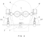
- Fig. 3 and Fig. 4 Front and side view of the inventive condylographs
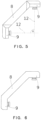
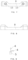
- Fig. 5 to Fig. 8 External views of the housing, which contains two cameras
- Fig. 9 a schematic view of a reference marker pair.
- the skull together with the lower jaw in the centered joint position of the patient defines a Cartesian coordinate system, which the components of the condylograph according to the invention are based on.
- the common hinge axis of the right and left jaw joints form the y-axis of this coordinate system. It is in Fig. 1 cannot be seen due to the selected perspective or the y-axis points vertically into the plane of the paper.
- the x-axis is perpendicular to the y-axis and runs along the connecting line between the back of the head and the nose or from the joint axis at the level of a front reference point of the patient's skull to the front.
- the joint axis is usually the common hinge axis of both jaw joints in a centric jaw joint position; the front reference point is usually the orbital point as the lowest point of the front edge of the left eye socket.
- the z-axis is again perpendicular to the x- and y-axis, which lies in the vertical axis of the patient's skull 6 or essentially parallel to the longest extension of the spine of a patient in a standing or sitting position with the head raised.
- Fig. 2 The same coordinate system is shown on the technical model of a lower jaw 7. All axes are perpendicular to one another, which is not essential for explaining or practicing the invention.
- the condylograph comprises two parts, namely a lower arch 2, which is temporarily connected to the lower jaw 7, for example via a dental clamp 11, and an upper arch 1, which can be temporarily connected to the patient's skull 6.
- the upper arch 1 can be rested on the bridge of the nose like a pair of glasses and the ears. Additional fastening means are conceivable.
- the upper arch 1 can also be designed like a pair of glasses with one frame part in front of each eye of the patient, as shown in the Fig.
- a housing 8 in which two cameras 13 are located is attached to the parts of the upper arch 1 that extend over one side of the patient.
- the two cameras 13 look out of the housing 8 onto parts of the lower arch 2.
- Both the upper arch 1 and the lower arch 2 cover an angular range of 180 degrees in the xy plane around the patient's face. When attached, the two arches 1, 2 are approximately parallel to one another.
- the camera(s) 13 or a housing 8 with internal cameras 13 can be attached to the lower arch 2.
- the lower arch 2 is firmly connected at essentially only one point to the patient's lower teeth or palate and thus to his lower jaw 7 by gluing, clamping or other temporary fixation.
- the lower arch 2 can also take on any shape, but it is advantageous that it is as light as possible in order to save weight and thus to be easy to handle and carry, and is therefore made of light, relatively thin material.
- the lower arch 2 also goes around the patient's skull 6, so that at least the ends 3, 3' of the lower arch 2 are at the level of the patient's jaw joints on both sides.
- the lower arch 2 is advantageously made in one piece, which simplifies manufacture and ensures long-term use; however, it can also be made up of a few parts, as long as all the parts joined together form a single, solid construction.
- the reference markers 4 are attached to the upper arch 1.
- the cameras 13 on the lower arch 2 are arranged in a particularly lightweight construction where the reference markers 4 are in the first embodiment, namely at the ends 3, 3' of the lower arch 2, which are located approximately on the anatomically localized joint axis or the individual hinge axis of the patient's jaw joint, i.e. at the height of the point of the patient's joint axis and an area of up to a maximum of 3 mm around it.
- the exact point is expediently not touched by one of the cameras 13, but by the center of the connecting line between, for example, two cameras 13 on each side of the patient.
- the upper reference markers 4 are also ultimately located in the intersecting fields of view of the cameras 13.
- the area 10 visible from both cameras 13 thus records the movement of one or more reference markers 4 (see Fig. 9 ), while the patient performs prescribed movements of the jaw.
- the invention solves the problem with a reference marker 4, which can be a geometric point and does not have to be a pattern.
- the use of two or more reference markers 4 per patient side can, however, be advantageous (see below); the measurement of a rotational component in the jaw movement is only possible with at least two reference markers 4 per side.
- a corresponding embodiment is shown in the Fig. 3 and 4 shown, where the two reference markers 4 per patient side are spaced from each other not only in the x-direction, but also in the y- and z-direction.
- a side view of the housing 8 the cameras 13 are located in boxes 9 at the ends of the housing 8, which can already specify an angle to each other. This is therefore bone-shaped, although other shapes are also conceivable.
- the viewing axes 12 of the cameras 13 intersect at an angle ⁇ , which in the example shown is 90 degrees. Other angle ranges are also possible.
- the angle can also have a selectable value, for example between about 30 and 150 degrees, whereby every movement of the filmed reference marker in the xz plane is recorded by the cameras 13.
- Fig. 6 shows the rear view of the housing 8 with the two boxes 9
- Fig. 7 shows the bottom view of the housing 8 with an opening for each of the cameras 13.
- Fig. 8 shows the housing 8 in plan view, which represents a housing 8 that is essentially closed in all spatial directions, so that sufficient protection for the cameras 13 as well as a predefined fixed spacing and angular position of the two cameras 13 is achieved, furthermore, due to at least relative watertightness, a good washability or wipe disinfection of this component of the condylograph and finally a reduced risk of injury to its components when handling the condylograph according to the invention.
- the upper arch 1 should also be as light as possible to improve portability for the patient. This means that as many components as possible should be made of light materials and these materials should be used sparingly.
- the electronic components or the components that actually take part in the measurement should be as simple and miniaturized as possible.
- the reference markers 4 consist of balls which are connected to the lower arch 2 via an adapter 5. It has proven advantageous to use two balls per patient side, which must be at least, as shown in Fig. 9 shown, in the state connected to the lower arch 2, are spaced apart in the x-direction and, if necessary, in the negative y-direction in order to make a three-dimensional movement of the lower jaw 7 and also a rotation of the lower jaw 7 during its movement detectable. Ideally, only one Spacing in the x-direction is required; however, in order to ensure that the balls do not cover each other in practice, they are spaced apart from each other in all three spatial directions.
- the advantage of the invention is that the reference markers 4 do not have any further optical features. For example, patterns or other special shapes or a higher number of reference markers 4 are not required.
- the housing 8 is either equipped with light sources (not shown) in addition to the cameras 13, which sufficiently illuminate the field of view 10 of the cameras 13 with infrared light, or the reference markers 4 are active and emit light independently.
- LED light sources have the advantage of precisely defining the frequency of the emitted light, being lightweight and inexpensive.
- the reference spheres are coated with an infrared paint, and the cameras 13 are particularly sensitive in the infrared spectral range.
- the reference markers 4 themselves are equipped with internal infrared light sources, e.g. infrared LEDs. This is advantageous because, on the one hand, the temperature development around the cameras 13 is drastically reduced and, on the other hand, the field of view can be set to the exact frequency required; this also makes it easier to filter out background information via thresholding. Less energy is also required and the weight on the upper arch is reduced.
- the measurement can be carried out in almost any ambient light.
- This has the advantage that the existing light and shadow conditions in the dental practice do not have to be adjusted or changed in any way for the measurement itself.
- This makes handling the condylograph according to the invention easier.
- the ends of the lower arch 3, 3' or the entire lower arch 2 are coated with a color that absorbs infrared light particularly strongly. The reference spheres thus stand out more clearly in the field of view of the cameras 13.
- a specific measurement can therefore be carried out in just a few simple steps.
- the patient can put on the upper arch 1 while standing or sitting comfortably and then have the lower arch 2 attached to his lower jaw 7.
- the cameras 13 and the reference markers 4 are already in the correct spatial arrangement relative to one another. If necessary, adjustments are made using simple mechanical means.
- the condylograph according to the invention does not require a stationary device, no complex and movement-impairing or movement-altering connections of equipment to the patient. No disruptive connections between the two arches are required either. Only one or two cables (one per patient side) lead from the upper arch 1 to the computer or a computer unit that is supplied as part of the system (neither shown), in which the evaluation of the measurement results takes place automatically.
- This cable can follow the USB system and is therefore a comparatively thin, light and very flexible cable that will neither disturb the patient nor alter his jaw movement. Furthermore, a USB cable is easily replaceable.
- the low weight of the lower arch 2 does not bother the patient either.
- the software installed on the evaluation computer now controls the cameras 13 in the housing 8 and records the image material from the cameras 13 while the patient performs the specified jaw movements. No further changes to the patient or the dentist's office are necessary. The measurement is then already completed.
- the housing 8 is also planned to attach the housing 8 to the upper arch 1 in a pivotable manner.
- the housing 8 and with it the field of view 10 of the cameras 13 can be pivoted in the x-z plane, for example, if the reference markers 4 on the lower arch 2 are at a different height or in a different area on the patient's side and measuring the jaw movement appears more advantageous there.
- the housing 8 is connected via a joint which allows predefined pivoting means of the housing 8 and temporarily locks them.
- a housing 8 is attached to the then still free side of the upper arch 1 (as well as corresponding reference markers 4 on the lower arch 2) in order to also measure in parallel or alternately on the now second side of the patient.
- the condylograph is advantageously connected to a display device either directly or via a computer-type control and recording device that carries out the control and evaluation, which shows the person supervising the measurement results, the status of the condylograph or just a rudimentary signal that confirms the successful measurement.
- key data for dental medical articulators can be determined automatically using software without human intervention and without any significant time elapse.
- the recording data can be converted to any intercondylar distance (for example the actual intercondylar distance of the patient) when recorded on both sides and simultaneously. This key data can be conveniently saved and provided in the form of a printout, a file or similar.
Landscapes
- Health & Medical Sciences (AREA)
- Life Sciences & Earth Sciences (AREA)
- Oral & Maxillofacial Surgery (AREA)
- Public Health (AREA)
- Veterinary Medicine (AREA)
- Biophysics (AREA)
- Dentistry (AREA)
- Biomedical Technology (AREA)
- Animal Behavior & Ethology (AREA)
- General Health & Medical Sciences (AREA)
- Engineering & Computer Science (AREA)
- Pathology (AREA)
- Physics & Mathematics (AREA)
- Epidemiology (AREA)
- Heart & Thoracic Surgery (AREA)
- Medical Informatics (AREA)
- Molecular Biology (AREA)
- Surgery (AREA)
- Physical Education & Sports Medicine (AREA)
- Orthopedic Medicine & Surgery (AREA)
- Rheumatology (AREA)
- Physiology (AREA)
- Dental Tools And Instruments Or Auxiliary Dental Instruments (AREA)
Applications Claiming Priority (2)
| Application Number | Priority Date | Filing Date | Title |
|---|---|---|---|
| ATA220/2017A AT519357B1 (de) | 2017-05-24 | 2017-05-24 | Kiefergelenkaufzeichnungssystem |
| PCT/AT2018/000013 WO2018213857A1 (de) | 2017-05-24 | 2018-03-12 | Kiefergelenkaufzeichnungssystem |
Publications (2)
| Publication Number | Publication Date |
|---|---|
| EP3630003A1 EP3630003A1 (de) | 2020-04-08 |
| EP3630003B1 true EP3630003B1 (de) | 2024-11-27 |
Family
ID=61912906
Family Applications (1)
| Application Number | Title | Priority Date | Filing Date |
|---|---|---|---|
| EP18716478.5A Active EP3630003B1 (de) | 2017-05-24 | 2018-03-12 | Kiefergelenkaufzeichnungssystem |
Country Status (5)
| Country | Link |
|---|---|
| EP (1) | EP3630003B1 (pl) |
| AT (1) | AT519357B1 (pl) |
| ES (1) | ES3009945T3 (pl) |
| PL (1) | PL3630003T3 (pl) |
| WO (1) | WO2018213857A1 (pl) |
Families Citing this family (1)
| Publication number | Priority date | Publication date | Assignee | Title |
|---|---|---|---|---|
| CN114387303A (zh) * | 2021-12-30 | 2022-04-22 | 北京科技大学 | 一种基于视频图像处理的髁突运动轨迹描记装置 |
Family Cites Families (9)
| Publication number | Priority date | Publication date | Assignee | Title |
|---|---|---|---|---|
| FR2639212A1 (fr) * | 1988-11-18 | 1990-05-25 | Hennson Int | Dispositif de mesure et d'analyse de mouvements du corps humain ou de parties de celui-ci |
| EP1000589A3 (de) * | 1998-11-09 | 2002-08-14 | Synthese Dentale Forschungs- und Entwicklungsgesellschaft mbH | Schnellübertragungsbogen |
| JP2001112743A (ja) * | 1999-10-18 | 2001-04-24 | Rikogaku Shinkokai | 三次元顎運動表示装置、方法及び三次元顎運動表示プログラムを記憶した記憶媒体 |
| DE20114192U1 (de) * | 2001-08-29 | 2001-12-06 | SAM Präzisionstechnik GmbH, 80637 München | Anatomischer Transferbogen mit Nivelliereinrichtung |
| DE102004002953B4 (de) * | 2004-01-21 | 2017-07-27 | Zebris Medical Gmbh | Verfahren und Vorrichtung zur Bestimmung aller Bewegungsfreiheitsgrade und Positionen des Unterkiefers bezüglich des Oberkiefers |
| DE202004004955U1 (de) * | 2004-03-26 | 2004-06-09 | SAM Präzisionstechnik GmbH | Kombinationsvorrichtung zur Registrierung der Unterkieferbewegungen in Bezug auf den Schädel einerseits und zur schädelgerechten Übertragung von Oberkiefermodellen in einen Artikulator andererseits |
| DE102010033109A1 (de) * | 2010-08-02 | 2012-02-02 | Zebris Medical Gmbh | Vorrichtung zur Erfassung von Bewegungen eines Unterkiefers |
| DE202013008707U1 (de) * | 2013-03-11 | 2014-02-19 | Evgeniy Mikhailovich Roschin | Vorrichtung zur Diagnostik von Unterkieferbewegungen |
| DE202016100240U1 (de) * | 2015-03-09 | 2016-02-03 | Zebris Medical Gmbh | Optisches Kieferregistrierungssystem auf der Basis von Stereokameras |
-
2017
- 2017-05-24 AT ATA220/2017A patent/AT519357B1/de active
-
2018
- 2018-03-12 EP EP18716478.5A patent/EP3630003B1/de active Active
- 2018-03-12 ES ES18716478T patent/ES3009945T3/es active Active
- 2018-03-12 WO PCT/AT2018/000013 patent/WO2018213857A1/de not_active Ceased
- 2018-03-12 PL PL18716478.5T patent/PL3630003T3/pl unknown
Also Published As
| Publication number | Publication date |
|---|---|
| PL3630003T4 (pl) | 2025-04-28 |
| WO2018213857A1 (de) | 2018-11-29 |
| PL3630003T3 (pl) | 2025-04-28 |
| EP3630003A1 (de) | 2020-04-08 |
| AT519357A4 (de) | 2018-06-15 |
| ES3009945T3 (en) | 2025-03-31 |
| AT519357B1 (de) | 2018-06-15 |
Similar Documents
| Publication | Publication Date | Title |
|---|---|---|
| EP2337498B1 (de) | Verfahren zur erstellung einer dentalen 3d-röntgenaufnahme | |
| DE3437900C2 (de) | Sterotaktisches Gerät zum Anbringen von Markierungsmitteln am Kopf eines Patienten | |
| EP0188819A1 (de) | Vorrichtung zur Messung der Positionen und Bewegungen des Unterkiefers relativ zum Oberkiefer | |
| EP1774473B1 (de) | Verfahren zur positionsbestimmung und positionsmesssystem | |
| DE102006046271B4 (de) | Positioniervorrichtung für ein Panorama-Röntgengerät | |
| CH643728A5 (de) | Abtastvorrichtung fuer mandibularbewegungen. | |
| DE202013105962U1 (de) | Kopfbogen einer Vorrichtung zur Bestimmung der Position und von Bewegungsfreiheitsgraden des Unterkiefers | |
| EP3630003B1 (de) | Kiefergelenkaufzeichnungssystem | |
| DE102004015383B4 (de) | Kombinationsvorrichtung zur Registrierung der Unterkieferbewegungen in Bezug auf den Schädel einerseits und zur schädelgerechten Übertragung von Oberkiefermodellen in einen Artikulator andererseits | |
| DE10142139A1 (de) | Anatomischer Transferbogen mit Nivelliereinrichtung | |
| DE202009011060U1 (de) | Halteeinrichtung zum Einscannen eines Oberkiefermodells und eines Unterkiefermodells | |
| DE102013000012B4 (de) | Messanordnung und Verfahren zur opto-elektronischen Erfassung der Relativbewegung zwischen Ober- und Unterkiefer einer Person | |
| DE2825204C2 (de) | Vorrichtung zur dreidimensionalen Erfassung und Aufzeichnung der Bewegung der Kiefergelenke eines Patienten | |
| DE2950847C2 (de) | Zahnärztliche Vorrichtung zur Erfassung der räumlichen Lage und Bewegung des menschlichen Unterkiefers in bezug zur Schädelreferenzebene des Patienten | |
| DE102017005185B4 (de) | Dentaldatengeber zur Bereitstellung von Eingangsdaten für die maschinengesteuerte Erstellung von Zahnersatz oder dergleichen | |
| DE4411907A1 (de) | Verfahren und Vorrichtung zur Bestimmung von Position und Bewegung variabler Achsen von Gelenken | |
| DE102008060504A1 (de) | Verfahren und Vorrichtung zur Erfassung artikulierter Kiefermodelle mit 3D-Sensorik | |
| DE102010018825B4 (de) | Vorrichtung und Verfahren zur Positionierung eines realen Unterkiefermodells und eines Oberkiefermodells zur Herstellung einer Schiene oder Prothese zur Korrektur der Kondylenposition eines Kiefergelenks | |
| DE4330297B4 (de) | Artikulator mit Anbauelementen für wenigstens einen Gesichtsbogen | |
| LU503874B1 (de) | Eine Zahnimplantat-Prüfvorrichtung | |
| DE102007020675A1 (de) | Vorrichtung zur kauebenenbezogenen Diagnostik | |
| WO2016120342A1 (de) | Verfahren und vorrichtung zur bestimmung von werten eines gebisses | |
| DE19928268B4 (de) | Vorrichtung zur Simulation von Kiefergelenkstellungen | |
| DE202004004955U1 (de) | Kombinationsvorrichtung zur Registrierung der Unterkieferbewegungen in Bezug auf den Schädel einerseits und zur schädelgerechten Übertragung von Oberkiefermodellen in einen Artikulator andererseits | |
| DE202016000353U1 (de) | Vorrichtung zur räumlichen Positionierung des Oberkiefers unter Berücksichtigung individueller Parameter und Okklusionsgabel mit Bestimmung der Position im Raum |
Legal Events
| Date | Code | Title | Description |
|---|---|---|---|
| STAA | Information on the status of an ep patent application or granted ep patent |
Free format text: STATUS: UNKNOWN |
|
| STAA | Information on the status of an ep patent application or granted ep patent |
Free format text: STATUS: THE INTERNATIONAL PUBLICATION HAS BEEN MADE |
|
| PUAI | Public reference made under article 153(3) epc to a published international application that has entered the european phase |
Free format text: ORIGINAL CODE: 0009012 |
|
| STAA | Information on the status of an ep patent application or granted ep patent |
Free format text: STATUS: REQUEST FOR EXAMINATION WAS MADE |
|
| 17P | Request for examination filed |
Effective date: 20191024 |
|
| AK | Designated contracting states |
Kind code of ref document: A1 Designated state(s): AL AT BE BG CH CY CZ DE DK EE ES FI FR GB GR HR HU IE IS IT LI LT LU LV MC MK MT NL NO PL PT RO RS SE SI SK SM TR |
|
| AX | Request for extension of the european patent |
Extension state: BA ME |
|
| DAV | Request for validation of the european patent (deleted) | ||
| DAX | Request for extension of the european patent (deleted) | ||
| STAA | Information on the status of an ep patent application or granted ep patent |
Free format text: STATUS: EXAMINATION IS IN PROGRESS |
|
| 17Q | First examination report despatched |
Effective date: 20210830 |
|
| GRAP | Despatch of communication of intention to grant a patent |
Free format text: ORIGINAL CODE: EPIDOSNIGR1 |
|
| STAA | Information on the status of an ep patent application or granted ep patent |
Free format text: STATUS: GRANT OF PATENT IS INTENDED |
|
| INTG | Intention to grant announced |
Effective date: 20240620 |
|
| RAP3 | Party data changed (applicant data changed or rights of an application transferred) |
Owner name: GAMMA MEDIZINISCH-WISSENSCHAFTLICHEFORTBILDUNGS-GMBH |
|
| GRAS | Grant fee paid |
Free format text: ORIGINAL CODE: EPIDOSNIGR3 |
|
| GRAA | (expected) grant |
Free format text: ORIGINAL CODE: 0009210 |
|
| STAA | Information on the status of an ep patent application or granted ep patent |
Free format text: STATUS: THE PATENT HAS BEEN GRANTED |
|
| AK | Designated contracting states |
Kind code of ref document: B1 Designated state(s): AL AT BE BG CH CY CZ DE DK EE ES FI FR GB GR HR HU IE IS IT LI LT LU LV MC MK MT NL NO PL PT RO RS SE SI SK SM TR |
|
| REG | Reference to a national code |
Ref country code: GB Ref legal event code: FG4D Free format text: NOT ENGLISH |
|
| REG | Reference to a national code |
Ref country code: CH Ref legal event code: EP |
|
| REG | Reference to a national code |
Ref country code: IE Ref legal event code: FG4D Free format text: LANGUAGE OF EP DOCUMENT: GERMAN |
|
| REG | Reference to a national code |
Ref country code: DE Ref legal event code: R096 Ref document number: 502018015356 Country of ref document: DE |
|
| REG | Reference to a national code |
Ref country code: LT Ref legal event code: MG9D |
|
| REG | Reference to a national code |
Ref country code: ES Ref legal event code: FG2A Ref document number: 3009945 Country of ref document: ES Kind code of ref document: T3 Effective date: 20250331 |
|
| REG | Reference to a national code |
Ref country code: NL Ref legal event code: MP Effective date: 20241127 |
|
| PG25 | Lapsed in a contracting state [announced via postgrant information from national office to epo] |
Ref country code: HR Free format text: LAPSE BECAUSE OF FAILURE TO SUBMIT A TRANSLATION OF THE DESCRIPTION OR TO PAY THE FEE WITHIN THE PRESCRIBED TIME-LIMIT Effective date: 20241127 Ref country code: PT Free format text: LAPSE BECAUSE OF FAILURE TO SUBMIT A TRANSLATION OF THE DESCRIPTION OR TO PAY THE FEE WITHIN THE PRESCRIBED TIME-LIMIT Effective date: 20250327 Ref country code: IS Free format text: LAPSE BECAUSE OF FAILURE TO SUBMIT A TRANSLATION OF THE DESCRIPTION OR TO PAY THE FEE WITHIN THE PRESCRIBED TIME-LIMIT Effective date: 20250327 |
|
| PG25 | Lapsed in a contracting state [announced via postgrant information from national office to epo] |
Ref country code: FI Free format text: LAPSE BECAUSE OF FAILURE TO SUBMIT A TRANSLATION OF THE DESCRIPTION OR TO PAY THE FEE WITHIN THE PRESCRIBED TIME-LIMIT Effective date: 20241127 Ref country code: NL Free format text: LAPSE BECAUSE OF FAILURE TO SUBMIT A TRANSLATION OF THE DESCRIPTION OR TO PAY THE FEE WITHIN THE PRESCRIBED TIME-LIMIT Effective date: 20241127 |
|
| PG25 | Lapsed in a contracting state [announced via postgrant information from national office to epo] |
Ref country code: BG Free format text: LAPSE BECAUSE OF FAILURE TO SUBMIT A TRANSLATION OF THE DESCRIPTION OR TO PAY THE FEE WITHIN THE PRESCRIBED TIME-LIMIT Effective date: 20241127 |
|
| PG25 | Lapsed in a contracting state [announced via postgrant information from national office to epo] |
Ref country code: NO Free format text: LAPSE BECAUSE OF FAILURE TO SUBMIT A TRANSLATION OF THE DESCRIPTION OR TO PAY THE FEE WITHIN THE PRESCRIBED TIME-LIMIT Effective date: 20250227 |
|
| PG25 | Lapsed in a contracting state [announced via postgrant information from national office to epo] |
Ref country code: GR Free format text: LAPSE BECAUSE OF FAILURE TO SUBMIT A TRANSLATION OF THE DESCRIPTION OR TO PAY THE FEE WITHIN THE PRESCRIBED TIME-LIMIT Effective date: 20250228 Ref country code: LV Free format text: LAPSE BECAUSE OF FAILURE TO SUBMIT A TRANSLATION OF THE DESCRIPTION OR TO PAY THE FEE WITHIN THE PRESCRIBED TIME-LIMIT Effective date: 20241127 |
|
| PGFP | Annual fee paid to national office [announced via postgrant information from national office to epo] |
Ref country code: FR Payment date: 20250326 Year of fee payment: 8 |
|
| PGFP | Annual fee paid to national office [announced via postgrant information from national office to epo] |
Ref country code: GB Payment date: 20250306 Year of fee payment: 8 |
|
| PG25 | Lapsed in a contracting state [announced via postgrant information from national office to epo] |
Ref country code: RS Free format text: LAPSE BECAUSE OF FAILURE TO SUBMIT A TRANSLATION OF THE DESCRIPTION OR TO PAY THE FEE WITHIN THE PRESCRIBED TIME-LIMIT Effective date: 20250227 |
|
| PGFP | Annual fee paid to national office [announced via postgrant information from national office to epo] |
Ref country code: TR Payment date: 20250226 Year of fee payment: 8 |
|
| PG25 | Lapsed in a contracting state [announced via postgrant information from national office to epo] |
Ref country code: SM Free format text: LAPSE BECAUSE OF FAILURE TO SUBMIT A TRANSLATION OF THE DESCRIPTION OR TO PAY THE FEE WITHIN THE PRESCRIBED TIME-LIMIT Effective date: 20241127 |
|
| PGFP | Annual fee paid to national office [announced via postgrant information from national office to epo] |
Ref country code: PL Payment date: 20250226 Year of fee payment: 8 Ref country code: DE Payment date: 20250428 Year of fee payment: 8 |
|
| PG25 | Lapsed in a contracting state [announced via postgrant information from national office to epo] |
Ref country code: DK Free format text: LAPSE BECAUSE OF FAILURE TO SUBMIT A TRANSLATION OF THE DESCRIPTION OR TO PAY THE FEE WITHIN THE PRESCRIBED TIME-LIMIT Effective date: 20241127 |
|
| PGFP | Annual fee paid to national office [announced via postgrant information from national office to epo] |
Ref country code: ES Payment date: 20250401 Year of fee payment: 8 |
|
| PGFP | Annual fee paid to national office [announced via postgrant information from national office to epo] |
Ref country code: IT Payment date: 20250422 Year of fee payment: 8 |
|
| PG25 | Lapsed in a contracting state [announced via postgrant information from national office to epo] |
Ref country code: EE Free format text: LAPSE BECAUSE OF FAILURE TO SUBMIT A TRANSLATION OF THE DESCRIPTION OR TO PAY THE FEE WITHIN THE PRESCRIBED TIME-LIMIT Effective date: 20241127 |
|
| PG25 | Lapsed in a contracting state [announced via postgrant information from national office to epo] |
Ref country code: RO Free format text: LAPSE BECAUSE OF FAILURE TO SUBMIT A TRANSLATION OF THE DESCRIPTION OR TO PAY THE FEE WITHIN THE PRESCRIBED TIME-LIMIT Effective date: 20241127 |
|
| PG25 | Lapsed in a contracting state [announced via postgrant information from national office to epo] |
Ref country code: SK Free format text: LAPSE BECAUSE OF FAILURE TO SUBMIT A TRANSLATION OF THE DESCRIPTION OR TO PAY THE FEE WITHIN THE PRESCRIBED TIME-LIMIT Effective date: 20241127 |
|
| PG25 | Lapsed in a contracting state [announced via postgrant information from national office to epo] |
Ref country code: CZ Free format text: LAPSE BECAUSE OF FAILURE TO SUBMIT A TRANSLATION OF THE DESCRIPTION OR TO PAY THE FEE WITHIN THE PRESCRIBED TIME-LIMIT Effective date: 20241127 |
|
| REG | Reference to a national code |
Ref country code: DE Ref legal event code: R097 Ref document number: 502018015356 Country of ref document: DE |
|
| PG25 | Lapsed in a contracting state [announced via postgrant information from national office to epo] |
Ref country code: SE Free format text: LAPSE BECAUSE OF FAILURE TO SUBMIT A TRANSLATION OF THE DESCRIPTION OR TO PAY THE FEE WITHIN THE PRESCRIBED TIME-LIMIT Effective date: 20241127 |
|
| PLBE | No opposition filed within time limit |
Free format text: ORIGINAL CODE: 0009261 |
|
| STAA | Information on the status of an ep patent application or granted ep patent |
Free format text: STATUS: NO OPPOSITION FILED WITHIN TIME LIMIT |
|
| REG | Reference to a national code |
Ref country code: CH Ref legal event code: L10 Free format text: ST27 STATUS EVENT CODE: U-0-0-L10-L00 (AS PROVIDED BY THE NATIONAL OFFICE) Effective date: 20251008 |
|
| PG25 | Lapsed in a contracting state [announced via postgrant information from national office to epo] |
Ref country code: MC Free format text: LAPSE BECAUSE OF FAILURE TO SUBMIT A TRANSLATION OF THE DESCRIPTION OR TO PAY THE FEE WITHIN THE PRESCRIBED TIME-LIMIT Effective date: 20241127 |
|
| REG | Reference to a national code |
Ref country code: CH Ref legal event code: H13 Free format text: ST27 STATUS EVENT CODE: U-0-0-H10-H13 (AS PROVIDED BY THE NATIONAL OFFICE) Effective date: 20251023 |
|
| 26N | No opposition filed |
Effective date: 20250828 |
|
| PG25 | Lapsed in a contracting state [announced via postgrant information from national office to epo] |
Ref country code: LU Free format text: LAPSE BECAUSE OF NON-PAYMENT OF DUE FEES Effective date: 20250312 |
|
| REG | Reference to a national code |
Ref country code: BE Ref legal event code: MM Effective date: 20250331 |
|
| PG25 | Lapsed in a contracting state [announced via postgrant information from national office to epo] |
Ref country code: BE Free format text: LAPSE BECAUSE OF NON-PAYMENT OF DUE FEES Effective date: 20250331 |
|
| PG25 | Lapsed in a contracting state [announced via postgrant information from national office to epo] |
Ref country code: CH Free format text: LAPSE BECAUSE OF NON-PAYMENT OF DUE FEES Effective date: 20250331 |
|
| PG25 | Lapsed in a contracting state [announced via postgrant information from national office to epo] |
Ref country code: IE Free format text: LAPSE BECAUSE OF NON-PAYMENT OF DUE FEES Effective date: 20250312 |