EP3628942B1 - Procédé permettant de commander un système de compression de vapeur à une pression d'aspiration réduite - Google Patents
Procédé permettant de commander un système de compression de vapeur à une pression d'aspiration réduite Download PDFInfo
- Publication number
- EP3628942B1 EP3628942B1 EP18196411.5A EP18196411A EP3628942B1 EP 3628942 B1 EP3628942 B1 EP 3628942B1 EP 18196411 A EP18196411 A EP 18196411A EP 3628942 B1 EP3628942 B1 EP 3628942B1
- Authority
- EP
- European Patent Office
- Prior art keywords
- compressor
- receiver
- pressure
- refrigerant
- suction pressure
- Prior art date
- Legal status (The legal status is an assumption and is not a legal conclusion. Google has not performed a legal analysis and makes no representation as to the accuracy of the status listed.)
- Active
Links
- 230000006835 compression Effects 0.000 title claims description 61
- 238000007906 compression Methods 0.000 title claims description 61
- 238000000034 method Methods 0.000 title claims description 32
- 239000003507 refrigerant Substances 0.000 claims description 114
- 239000012530 fluid Substances 0.000 claims description 30
- 238000012544 monitoring process Methods 0.000 claims description 2
- 239000007788 liquid Substances 0.000 description 16
- 230000007423 decrease Effects 0.000 description 5
- 230000003247 decreasing effect Effects 0.000 description 4
- 238000005259 measurement Methods 0.000 description 4
- 238000010586 diagram Methods 0.000 description 2
- 238000010438 heat treatment Methods 0.000 description 2
- 238000005057 refrigeration Methods 0.000 description 2
- 238000001816 cooling Methods 0.000 description 1
- 230000000694 effects Effects 0.000 description 1
- 238000005265 energy consumption Methods 0.000 description 1
Images


Classifications
-
- F—MECHANICAL ENGINEERING; LIGHTING; HEATING; WEAPONS; BLASTING
- F25—REFRIGERATION OR COOLING; COMBINED HEATING AND REFRIGERATION SYSTEMS; HEAT PUMP SYSTEMS; MANUFACTURE OR STORAGE OF ICE; LIQUEFACTION SOLIDIFICATION OF GASES
- F25B—REFRIGERATION MACHINES, PLANTS OR SYSTEMS; COMBINED HEATING AND REFRIGERATION SYSTEMS; HEAT PUMP SYSTEMS
- F25B49/00—Arrangement or mounting of control or safety devices
- F25B49/02—Arrangement or mounting of control or safety devices for compression type machines, plants or systems
-
- F—MECHANICAL ENGINEERING; LIGHTING; HEATING; WEAPONS; BLASTING
- F25—REFRIGERATION OR COOLING; COMBINED HEATING AND REFRIGERATION SYSTEMS; HEAT PUMP SYSTEMS; MANUFACTURE OR STORAGE OF ICE; LIQUEFACTION SOLIDIFICATION OF GASES
- F25B—REFRIGERATION MACHINES, PLANTS OR SYSTEMS; COMBINED HEATING AND REFRIGERATION SYSTEMS; HEAT PUMP SYSTEMS
- F25B2400/00—General features or devices for refrigeration machines, plants or systems, combined heating and refrigeration systems or heat-pump systems, i.e. not limited to a particular subgroup of F25B
- F25B2400/07—Details of compressors or related parts
- F25B2400/075—Details of compressors or related parts with parallel compressors
-
- F—MECHANICAL ENGINEERING; LIGHTING; HEATING; WEAPONS; BLASTING
- F25—REFRIGERATION OR COOLING; COMBINED HEATING AND REFRIGERATION SYSTEMS; HEAT PUMP SYSTEMS; MANUFACTURE OR STORAGE OF ICE; LIQUEFACTION SOLIDIFICATION OF GASES
- F25B—REFRIGERATION MACHINES, PLANTS OR SYSTEMS; COMBINED HEATING AND REFRIGERATION SYSTEMS; HEAT PUMP SYSTEMS
- F25B2400/00—General features or devices for refrigeration machines, plants or systems, combined heating and refrigeration systems or heat-pump systems, i.e. not limited to a particular subgroup of F25B
- F25B2400/13—Economisers
-
- F—MECHANICAL ENGINEERING; LIGHTING; HEATING; WEAPONS; BLASTING
- F25—REFRIGERATION OR COOLING; COMBINED HEATING AND REFRIGERATION SYSTEMS; HEAT PUMP SYSTEMS; MANUFACTURE OR STORAGE OF ICE; LIQUEFACTION SOLIDIFICATION OF GASES
- F25B—REFRIGERATION MACHINES, PLANTS OR SYSTEMS; COMBINED HEATING AND REFRIGERATION SYSTEMS; HEAT PUMP SYSTEMS
- F25B2400/00—General features or devices for refrigeration machines, plants or systems, combined heating and refrigeration systems or heat-pump systems, i.e. not limited to a particular subgroup of F25B
- F25B2400/16—Receivers
-
- F—MECHANICAL ENGINEERING; LIGHTING; HEATING; WEAPONS; BLASTING
- F25—REFRIGERATION OR COOLING; COMBINED HEATING AND REFRIGERATION SYSTEMS; HEAT PUMP SYSTEMS; MANUFACTURE OR STORAGE OF ICE; LIQUEFACTION SOLIDIFICATION OF GASES
- F25B—REFRIGERATION MACHINES, PLANTS OR SYSTEMS; COMBINED HEATING AND REFRIGERATION SYSTEMS; HEAT PUMP SYSTEMS
- F25B2400/00—General features or devices for refrigeration machines, plants or systems, combined heating and refrigeration systems or heat-pump systems, i.e. not limited to a particular subgroup of F25B
- F25B2400/23—Separators
-
- F—MECHANICAL ENGINEERING; LIGHTING; HEATING; WEAPONS; BLASTING
- F25—REFRIGERATION OR COOLING; COMBINED HEATING AND REFRIGERATION SYSTEMS; HEAT PUMP SYSTEMS; MANUFACTURE OR STORAGE OF ICE; LIQUEFACTION SOLIDIFICATION OF GASES
- F25B—REFRIGERATION MACHINES, PLANTS OR SYSTEMS; COMBINED HEATING AND REFRIGERATION SYSTEMS; HEAT PUMP SYSTEMS
- F25B2500/00—Problems to be solved
- F25B2500/19—Calculation of parameters
-
- F—MECHANICAL ENGINEERING; LIGHTING; HEATING; WEAPONS; BLASTING
- F25—REFRIGERATION OR COOLING; COMBINED HEATING AND REFRIGERATION SYSTEMS; HEAT PUMP SYSTEMS; MANUFACTURE OR STORAGE OF ICE; LIQUEFACTION SOLIDIFICATION OF GASES
- F25B—REFRIGERATION MACHINES, PLANTS OR SYSTEMS; COMBINED HEATING AND REFRIGERATION SYSTEMS; HEAT PUMP SYSTEMS
- F25B2600/00—Control issues
- F25B2600/02—Compressor control
- F25B2600/025—Compressor control by controlling speed
-
- F—MECHANICAL ENGINEERING; LIGHTING; HEATING; WEAPONS; BLASTING
- F25—REFRIGERATION OR COOLING; COMBINED HEATING AND REFRIGERATION SYSTEMS; HEAT PUMP SYSTEMS; MANUFACTURE OR STORAGE OF ICE; LIQUEFACTION SOLIDIFICATION OF GASES
- F25B—REFRIGERATION MACHINES, PLANTS OR SYSTEMS; COMBINED HEATING AND REFRIGERATION SYSTEMS; HEAT PUMP SYSTEMS
- F25B2600/00—Control issues
- F25B2600/02—Compressor control
- F25B2600/027—Compressor control by controlling pressure
- F25B2600/0272—Compressor control by controlling pressure the suction pressure
-
- F—MECHANICAL ENGINEERING; LIGHTING; HEATING; WEAPONS; BLASTING
- F25—REFRIGERATION OR COOLING; COMBINED HEATING AND REFRIGERATION SYSTEMS; HEAT PUMP SYSTEMS; MANUFACTURE OR STORAGE OF ICE; LIQUEFACTION SOLIDIFICATION OF GASES
- F25B—REFRIGERATION MACHINES, PLANTS OR SYSTEMS; COMBINED HEATING AND REFRIGERATION SYSTEMS; HEAT PUMP SYSTEMS
- F25B2600/00—Control issues
- F25B2600/25—Control of valves
- F25B2600/2523—Receiver valves
Definitions
- the present invention relates to a method for controlling a vapour compression system comprising a compressor unit, a heat rejecting heat exchanger, a receiver, an expansion device and an evaporator arranged in a refrigerant path.
- the method according to the invention allows the vapour compression system to operate properly, even when the pressure prevailing inside the receiver is low.
- refrigerant circulates a refrigerant path having at least a compressor, a heat rejecting heat exchanger, an expansion device and an evaporator arranged therein.
- refrigerant is alternatingly compressed in the compressor and expanded in the expansion device, and heat exchange takes place between the refrigerant and appropriate secondary fluid flows or the ambient in the heat rejecting heat exchanger and the evaporator.
- cooling or heating of a closed volume can be obtained.
- a receiver is arranged in the refrigerant path between an outlet of the heat rejecting heat exchanger and an inlet of the expansion device.
- the refrigerant is separated into a liquid part and a gaseous part in the receiver, and the liquid part of the refrigerant is supplied to the evaporator, via the expansion device.
- the gaseous part of the refrigerant may be supplied to a compressor.
- the vapour compression system When the pressure prevailing inside the receiver is very low, the vapour compression system may not be able to operate properly. For instance, no or an insufficient flow of refrigerant may be supplied to the evaporator, and thereby the heat exchange taking place there will be insufficient, or even non-existent. A very low receiver pressure may even result in a situation where compressors are unable to start, and the vapour compression system will therefore stop operating.
- WO 2017/067858 A1 discloses a method for controlling a vapour compression system in which a pressure prevailing inside a receiver is controlled in accordance with opening degrees of one or more expansion devices, each being arranged to control a supply of refrigerant to an evaporator
- EP 3 023 712 A1 discloses a method for controlling a vapour compression system in which a pressure prevailing inside a receiver is controlled by calculating a setpoint value for a pressure inside the receiver and operating the compressor unit in accordance with the calculated setpoint value.
- the invention provides a method for controlling a vapour compression system as defined in claim 1.
- the method comprises a compressor unit comprising one or more compressors, a heat rejecting heat exchanger, a receiver, an expansion device and an evaporator arranged in a refrigerant path, the expansion device being arranged to control a supply of refrigerant to the evaporator, the method comprising the steps of:
- the method according to the invention is for controlling a vapour compression system.
- the term 'vapour compression system' should be interpreted to mean any system in which a flow of fluid medium, such as refrigerant, circulates and is alternatingly compressed and expanded, thereby providing either refrigeration or heating of a volume.
- the vapour compression system may be a refrigeration system, an air condition system, a heat pump, etc.
- the vapour compression system comprises a compressor unit comprising one or more compressors, a heat rejecting heat exchanger, a receiver, an expansion device and an evaporator arranged in a refrigerant path.
- the expansion device is arranged to control a supply of refrigerant to the evaporator.
- the heat rejecting heat exchanger could, e.g., be in the form of a condenser, in which refrigerant is at least partly condensed, or in the form of a gas cooler, in which refrigerant is cooled, but remains in a gaseous or trans-critical state.
- the expansion device could, e.g., be in the form of an expansion valve.
- refrigerant flowing in the refrigerant path is compressed by the compressor(s) of the compressor unit.
- the compressed refrigerant is supplied to the heat rejecting heat exchanger, where heat exchange takes place with the ambient, or with a secondary fluid flow across the heat rejecting heat exchanger, in such a manner that heat is rejected from the refrigerant flowing through the heat rejecting heat exchanger.
- the heat rejecting heat exchanger is in the form of a condenser
- the refrigerant is at least partly condensed when passing through the heat rejecting heat exchanger.
- the heat rejecting heat exchanger is in the form of a gas cooler, the refrigerant flowing through the heat rejecting heat exchanger is cooled, but it remains in a gaseous or trans-critical state.
- the refrigerant is supplied to the receiver, possibly via a high pressure expansion device, such as a high pressure valve or an ejector.
- a high pressure expansion device such as a high pressure valve or an ejector.
- the refrigerant is separated into a liquid part and a gaseous part.
- the liquid part of the refrigerant is supplied to the expansion device, where expansion takes place and the pressure of the refrigerant is reduced, before the refrigerant is supplied to the evaporator.
- the refrigerant being supplied to the evaporator is thereby in a mixed gaseous and liquid state.
- the liquid part of the refrigerant is at least partly evaporated, while heat exchange takes place with the ambient, or with a secondary fluid flow across the evaporator, in such a manner that heat is absorbed by the refrigerant flowing through the evaporator.
- the refrigerant is supplied to the compressor unit.
- the gaseous part of the refrigerant in the receiver may be supplied to the compressor unit. Thereby the gaseous part of the refrigerant is not subjected to the pressure drop introduced by the expansion device, and the work required in order to compress the refrigerant can thereby be reduced. Accordingly, energy is conserved.
- a pressure value indicating a pressure prevailing inside the receiver is initially obtained.
- the pressure value could be derived from measurements of other parameters, such as measurements of pressure prevailing in other parts of the vapour compression system and/or measurements of temperature prevailing inside the receiver and/or in other parts of the vapour compression system.
- the obtained pressure value provides information regarding the current pressure inside the receiver.
- the obtained pressure value is compared to a first threshold pressure value.
- the first threshold pressure value may represent a pressure level inside the receiver, below which there is a risk that the vapour compression system will operate in an inefficient or inappropriate manner.
- the first threshold pressure value may be a fixed value, representing a pressure value below which the pressure prevailing inside the receiver should not be allowed to be.
- the first threshold pressure value may be a dynamical value which can be varied according to the prevailing ambient conditions, such as the outdoor temperature.
- 'suction pressure' should be interpreted to mean a pressure of refrigerant entering the compressor unit via the part of the refrigerant path which is connected to an outlet of the evaporator.
- the compressor(s) of the compressor unit When the suction pressure is reduced in this manner, the compressor(s) of the compressor unit will remove more refrigerant from the evaporator, because the pressure difference across the expansion device is increased. This will increase the flow of refrigerant through the evaporator, and thereby the vapour compression system will continue to operate in an appropriate manner, despite the low pressure inside the receiver.
- the step of controlling the compressor(s) of the compressor unit may comprise the steps of:
- the compressors of the compressor unit are controlled based on a setpoint value representing a desired suction pressure.
- This setpoint value may be a fixed value, or it may be variable in accordance with various operating conditions, e.g. according to the pressure prevailing inside the receiver.
- the suction pressure setpoint value is lowered from an initial suction pressure setpoint value, P 0,set , to a reduced suction pressure setpoint value, P 0,red.
- the initial suction pressure setpoint value, P 0,set represents a suction pressure which is appropriate and desirable under the prevailing operating conditions, i.e. it represents the suction pressure at which the vapour compression system would normally operate, under the given circumstances.
- the reduced suction pressure setpoint value, P 0,red is a suction pressure value which is lower than the initial suction pressure setpoint value, P 0,set , i.e. it is reduced as compared to this value.
- the reduced suction pressure setpoint value, P 0,red could, e.g., be a fixed amount lower than the initial suction pressure setpoint value, P 0,set , which could be a variable according to the operating conditions as described above.
- the compressor(s) of the compressor unit are then controlled based on the reduced suction pressure setpoint value, P 0,red , i.e. the compressor(s) are controlled in order to achieve this reduced suction pressure. This will decrease the actual suction pressure from a level corresponding to the initial suction pressure setpoint value, P 0,set , to a level corresponding to the reduced suction pressure setpoint value, P 0,red , and thereby a reduction in suction pressure is obtained.
- the suction pressure may be reduced in other ways, without changing a setpoint value.
- the step of reducing the suction pressure may comprise increasing the compressor capacity of the compressor unit.
- Such an increase in compressor capacity will also result in a reduced suction pressure. This could, e.g., include overruling the normal control of the compressor unit and/or forcing an additional compressor of the compressor unit to start.
- the method may further comprise the step of adjusting a secondary fluid flow across the heat rejecting heat exchanger, based on the obtained pressure value.
- the secondary fluid flow across the heat rejecting heat exchanger has an impact on the heat exchange taking place in the heat rejecting heat exchanger.
- An increase in the secondary fluid flow results in an increased heat transfer from the refrigerant to the secondary fluid, and a decrease in the secondary fluid flow results in a decreased heat transfer from the refrigerant to the secondary fluid flow.
- an adjustment of the secondary fluid flow results in an adjustment in the temperature and pressure of the refrigerant leaving the heat rejecting heat exchanger, and this has an impact on the liquid-vapour ratio of the refrigerant being supplied to the receiver. This, in turn, affects the pressure prevailing inside the receiver.
- the pressure prevailing inside the receiver can be adjusted by appropriately adjusting the secondary fluid flow across the heat rejecting heat exchanger.
- adjusting the secondary fluid flow across the heat rejecting heat exchanger is one of the measures which may be taken in order to maintain the pressure prevailing inside the receiver at an appropriate level.
- the secondary fluid flow across the heat rejecting heat exchanger is an air flow
- the secondary fluid flow may be adjusted by adjusting a fan speed of one or more fans driving the secondary fluid flow and/or by switching one or more fans on or off.
- the secondary fluid flow may be adjusted by adjusting one or more pumps driving the secondary fluid flow.
- the compressor unit may comprise at least one main compressor being fluidly connected to an outlet of the evaporator and at least one receiver compressor being fluidly connected to a gaseous outlet of the receiver, and the method may further comprise the step of controlling the at least one receiver compressor based on the obtained pressure value.
- refrigerant leaving the evaporator is supplied to the at least one main compressor, and refrigerant from the gaseous outlet of the receiver is supplied to the at least one receiver compressor.
- the receiver compressor removes gaseous refrigerant from the receiver and supplies compressed refrigerant to the heat rejecting heat exchanger.
- operating the receiver compressor reduces the pressure prevailing inside the receiver.
- Each of the compressors of the compressor unit may be permanently connected to the outlet of the evaporator or to the gaseous outlet of the receiver.
- at least some of the compressors may be provided with a valve arrangement allowing the compressor to be selectively connected to the outlet of the evaporator or to the gaseous outlet of the receiver.
- the available compressor capacity can be distributed in a suitable manner between 'main compressor capacity' and 'receiver compressor capacity', by appropriately operating the valve arrangement(s).
- the supply of refrigerant to the receiver compressor(s) could, e.g., be adjusted by switching one or more compressors between being connected to the outlet of the evaporator and being connected to the gaseous outlet of the receiver.
- the compressor speed of one or more receiver compressors could be adjusted.
- one or more receiver compressors could be switched on or off.
- the supply of refrigerant to the receiver compressor(s) could be adjusted by controlling a bypass valve arranged in a part of the refrigerant path interconnecting the gaseous outlet of the receiver and the main compressor(s).
- the step of obtaining a pressure value may comprise measuring the pressure prevailing inside the receiver.
- the pressure prevailing inside the receiver is directly measured, e.g. by means of a pressure sensor arranged inside the receiver.
- the pressure prevailing inside the receiver may be obtained in an indirect manner, e.g. by deriving the pressure from one or more other measured parameters, such as pressures prevailing in other parts of the vapour compression system and/or temperatures prevailing inside the receiver and/or in other parts of the vapour compression system.
- the obtained pressure value may be low pass filtered before being compared to the first threshold pressure value, in order to remove short term fluctuations in the signal.
- the step of controlling the compressor(s) of the compressor unit may comprise adjusting a compressor capacity of the compressor unit.
- the compressor capacity of the compressor unit affects how much refrigerant is removed from the suction. Accordingly, adjusting the compressor capacity of the compressor unit has an impact on the suction pressure. More particularly, and increase in the compressor capacity results in more refrigerant being removed from the suction line. Thus, the suction pressure is decreased in this case. Similarly, a decrease in the compressor capacity results in less refrigerant being removed from the suction line, and an increase in suction pressure.
- the step of adjusting a compressor capacity of the compressor unit may comprise switching one or more compressors on or off. Switching on a compressor which was previously switched off increases the total compressor capacity by an amount corresponding to the compressor capacity of the compressor being switched on. Similarly, switching off a compressor which was previously switched on decreases the total compressor capacity by an amount corresponding to the compressor capacity of the compressor being switched off.
- the compressor capacity is adjusted in discrete steps corresponding to the capacities of the available compressors.
- At least one of the compressors of the compressor unit may be a variable capacity compressor.
- the step of adjusting a compressor capacity of the compressor unit may comprise varying the compressor capacity of one or more variable capacity compressors, e.g. by varying the speed of one or more compressors.
- the method may further comprise the steps of:
- the pressure prevailing inside the receiver is monitored, e.g. continuously, in order to establish whether or not the low pressure which gave rise to the reduction in suction pressure remains.
- the monitored pressure prevailing inside the receiver is compared to a second threshold pressure value, and in the case that the monitored pressure is above the second threshold pressure value, the compressor(s) of the compressor unit is/are controlled in order to increase the suction pressure.
- the second threshold pressure value may be identical to the first threshold pressure value, in which case the suction pressure will be increased as soon as the pressure prevailing inside the receiver has increased to a level above the first threshold pressure value. However, in most cases the second threshold pressure value is higher than the first threshold pressure value in order to avoid repeatedly switching between reducing and increasing the suction pressure in the case that the pressure prevailing inside the receiver is approximately equal to the first threshold pressure value.
- a reduced suction pressure is only maintained as long as the pressure prevailing inside the receiver is so low that there is a risk that the vapour compression system may not operate in an appropriate manner.
- the suction pressure is once again allowed to increase.
- the step of controlling the compressor(s) of the compressor unit in order to increase the suction pressure may comprise increasing a suction pressure setpoint value, e.g. from a reduced suction pressure setpoint value, P 0,red , to an initial suction pressure setpoint value, P 0,set , i.e. the initial suction pressure setpoint value, P 0,set , may be restored.
- a suction pressure setpoint value e.g. from a reduced suction pressure setpoint value, P 0,red
- P 0,set initial suction pressure setpoint value
- P 0,set initial suction pressure setpoint value
- the vapour compression system may further comprise a high pressure expansion device arranged fluidly between an outlet of the heat rejecting heat exchanger and an inlet of the receiver. In this case the refrigerant leaving the heat rejecting heat exchanger undergoes expansion before being supplied to the receiver.
- the high pressure expansion device may be in the form of a high pressure valve, in which case the refrigerant is merely expanded when passing through the high pressure valve.
- the high pressure expansion device may be in the form of an ejector having a primary inlet connected to the outlet of the heat rejecting heat exchanger, an outlet connected to the receiver and a secondary inlet connected to the outlet of the evaporator.
- An ejector is a type of pump which uses the Venturi effect to increase the pressure energy of fluid at a suction inlet (or secondary inlet) of the ejector by means of a motive fluid supplied to a motive inlet (or primary inlet) of the ejector.
- the high pressure expansion device may comprise at least one high pressure valve and at least one ejector arranged fluidly in parallel.
- a pressure prevailing in the heat rejecting heat exchanger may be controlled by controlling a fluid flow through the high pressure expansion device. This could, e.g., include controlling an opening degree of the high pressure expansion device.
- Fig. 1 is a diagrammatic view of a vapour compression system 1 being controlled in accordance with a method according to a first embodiment of the invention.
- the vapour compression system 1 comprises a compressor unit 2 comprising one or more compressors 3, one of which is shown, a heat rejecting heat exchanger 4, a high pressure valve 5, a receiver 6, an expansion valve 7 and an evaporator 8 arranged in a refrigerant path.
- Refrigerant flowing in the refrigerant path is compressed by the compressor 3 before being supplied to the heat rejecting heat exchanger 4.
- heat exchange takes place between the refrigerant flowing through the heat rejecting heat exchanger 4 and the ambient or a secondary fluid flow across the heat rejecting heat exchanger 4, in such a manner that heat is rejected from the refrigerant.
- the heat rejecting heat exchanger 4 is in the form of a condenser, the refrigerant is thereby at least partly condensed.
- the heat rejecting heat exchanger 4 is in the form of a gas cooler, the refrigerant flowing through the heat rejecting heat exchanger 4 is cooled, but it remains in a gaseous or trans-critical state.
- the refrigerant leaving the heat rejecting heat exchanger 4 is passed through the high pressure valve 5, where it undergoes expansion before being supplied to the receiver 6.
- the refrigerant is separated into a liquid part and a gaseous part.
- the liquid part of the refrigerant leaves the receiver 6 via a liquid outlet 9, and is supplied to the expansion device 7, where it undergoes expansion before being supplied to the evaporator 8.
- the refrigerant being supplied to the evaporator 8 is thereby in a mixed gaseous and liquid state.
- the gaseous part of the refrigerant in the receiver 6 may be supplied directly to the compressor 3, via a gaseous outlet 10 and a bypass valve 11.
- the vapour compression system 1 may be controlled in the following manner.
- a pressure value indicating a pressure prevailing inside the receiver is obtained, e.g. by directly measuring the pressure by means of a pressure sensor arranged inside the receiver 6.
- the obtained pressure value is then compared to a first threshold pressure value.
- the first threshold pressure value may represent a pressure level inside the receiver 6, below which there is a risk that the vapour compression system 1 may not operate in an appropriate manner, because a low pressure inside the receiver 6 may lead to an insufficient supply of refrigerant to the evaporator 8.
- the compressor 3 is operated in order to reduce the suction pressure of the vapour compression system 1, i.e. the pressure of refrigerant being supplied to the compressor 3.
- This may, e.g., be obtained by increasing the compressor capacity of the compressor unit 2, e.g. by increasing a speed of the compressor 3, or by switching on an additional compressor 3.
- the suction pressure may be reduced by reducing a suction pressure setpoint value from an initial suction pressure setpoint value, P 0,set , to a reduced suction pressure setpoint value, P 0,red , and then control the compressor 3 based on the reduced suction pressure setpoint value, P 0,red .
- the suction pressure may once again be increased. This may, e.g., be obtained by restoring the initial suction pressure setpoint value, P 0,set , and then control the compressor 3 based on the restored, initial suction pressure setpoint value, P 0,set .
- Fig. 2 is a diagrammatic view of a vapour compression system 1 being controlled in accordance with a method according to a second embodiment of the invention.
- the vapour compression system 1 of Fig. 2 is very similar to the vapour compression system 1 of Fig. 1 , and it will therefore not be described in detail here.
- the compressor unit 2 further comprises a receiver compressor 12 connected to the gaseous outlet 10 of the receiver 6.
- gaseous refrigerant from the receiver 6 may be supplied directly to the receiver compressor 12, and may therefore be compressed without having to be mixed with refrigerant leaving the evaporator 8, and thereby without affecting the suction pressure of the vapour compression system 1.
- the vapour compression system 1 of Fig. 2 may be controlled essentially as described above with reference to Fig. 1 . Furthermore, the pressure prevailing inside the receiver 6 may be controlled by controlling the receiver compressor 12.
- Fig. 3 is a diagrammatic view of a vapour compression system 1 being controlled in accordance with a method according to a third embodiment of the invention.
- the vapour compression system 1 of Fig. 3 is very similar to the vapour compression system 1 of Fig. 2 , and it will therefore not be described in detail here.
- the vapour compression system 1 of Fig. 3 is not provided with a high pressure valve. Accordingly, the refrigerant leaving the heat rejecting heat exchanger 4 is supplied directly to the receiver 6 without undergoing expansion.
- the vapour compression system 1 of Fig. 3 may be controlled essentially as described above with reference to Fig. 1 .
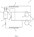
- Fig. 4 is a diagrammatic view of a vapour compression system 1 being controlled in accordance with a method according to a fourth embodiment of the invention.
- the vapour compression system 1 of Fig. 4 is very similar to the vapour compression system 1 of Fig. 2 , and it will therefore not be described in detail here.
- an ejector 13 is arranged fluidly in parallel with the high pressure valve 5. Accordingly, refrigerant leaving the heat rejecting heat exchanger 4 may pass through the high pressure valve 5 or through the ejector 13.
- the ejector 13 further has its secondary inlet connected to the outlet of the evaporator 8. Accordingly, refrigerant leaving the evaporator 8 may either be supplied to the compressor 3 or to the ejector 13.
- Fig. 5 is a log(P)-h diagram illustrating control of a vapour compression system in accordance with a method according to an embodiment of the invention.
- the vapour compression system being controlled could, e.g., be one of the vapour compression systems illustrated in Figs. 1-4 .
- the refrigerant is compressed in the compressor unit. Thereby the pressure as well as the enthalpy is increased.
- the refrigerant passes through the heat rejecting heat exchanger, where heat exchange takes place between the refrigerant and the ambient or a secondary fluid flow across the heat rejecting heat exchanger, in such a manner that heat is rejected from the refrigerant. Thereby the enthalpy is decreased, while the pressure remains constant.
- the refrigerant passes through a high pressure valve or an ejector, where the refrigerant undergoes expansion, and is received in the receiver. Thereby the pressure is decreased, while the enthalpy remains substantially constant.
- the refrigerant In the receiver the refrigerant is separated into a liquid part and a gaseous part.
- Point 18 represents the liquid part of the refrigerant in the receiver
- point 19 represents the gaseous part of the refrigerant in the receiver.
- the liquid part of the refrigerant in the receiver is passed through the expansion device, where it undergoes expansion. Thereby the pressure is reduced while the enthalpy remains constant.
- the refrigerant passes through the evaporator, where heat exchange takes place between the refrigerant and the ambient or a secondary fluid flow across the evaporator, in such a manner that heat is absorbed by the refrigerant. Thereby the enthalpy is increased, while the pressure remains constant.
- the gaseous part of the refrigerant in the receiver is supplied to the suction line via a bypass valve, and is thereby mixed with refrigerant leaving the evaporator. Passing the refrigerant through the bypass valve causes the pressure to decrease while the enthalpy remains constant.
- the position of the point 17 corresponds to the enthalpy of the refrigerant which leaves the heat rejecting heat exchanger and is supplied to the receiver.
- This enthalpy determines the liquid-vapour ratio of the refrigerant entering the receiver, and the liquid-vapour ratio of the refrigerant entering the receiver has an impact on the pressure prevailing in the receiver.
- the enthalpy of the refrigerant entering the receiver is low, corresponding to the point 17 being arranged far to the left, a large portion of the refrigerant entering the receiver is liquid.
- the liquid-vapour ratio of the refrigerant in the receiver, and thereby the pressure prevailing inside the receiver can be adjusted by adjusting the enthalpy of the refrigerant leaving the heat rejecting heat exchanger.
- This may be done by adjusting a secondary fluid flow across the heat rejecting heat exchanger, e.g. by adjusting a fan speed of one or more fans driving this flow. Adjusting the secondary fluid flow has an impact on the heat transfer taking place in the heat rejecting heat exchanger, and this in turn affects the enthalpy of the refrigerant leaving the heat rejecting heat exchanger.
- adjusting a secondary fluid flow across the heat rejecting heat exchanger is one way of controlling the pressure prevailing inside the receiver.
- the liquid-vapour ratio of the refrigerant entering the receiver should be such that at least 5% of the refrigerant is in the form of vapour.
- a certain minimum pressure difference between the pressure prevailing inside the receiver and the suction pressure i.e. the pressure difference across the expansion device, must be maintained.
- This pressure difference is represented by the difference between the pressure at point 19, representing the pressure prevailing inside the receiver, and the pressure at point 14, representing the suction pressure.
- this pressure difference becomes too small, it may initially be attempted to increase the pressure prevailing inside the receiver, e.g. in the manner described above. If this is not sufficient to maintain the minimum pressure difference, the suction pressure may be reduced instead. This could, e.g., be done in the manner described above with reference to Fig. 1 .
Landscapes
- Engineering & Computer Science (AREA)
- Physics & Mathematics (AREA)
- Mechanical Engineering (AREA)
- Thermal Sciences (AREA)
- General Engineering & Computer Science (AREA)
- Air Conditioning Control Device (AREA)
Claims (9)
- Procédé pour commander un système de compression de vapeur (1) comprenant une unité à compresseur (2) comprenant un ou plusieurs compresseurs (3, 12), un échangeur de chaleur à rejet de chaleur (4), un récepteur (6), un dispositif d'expansion (7) et un évaporateur (8) agencé dans un chemin de réfrigérant, le dispositif d'expansion (7) étant agencé pour commander une alimentation en réfrigérant à l'évaporateur (8), le procédé comprenant les étapes de :- l'obtention d'une valeur de pression indiquant une pression prévalant à l'intérieur du récepteur (6),- la comparaison de la valeur de pression obtenue à une première valeur de pression de seuil, et- au cas où la valeur de pression obtenue est inférieure à la première valeur de pression de seuil, la commande du ou des compresseur(s) (3, 12) de l'unité à compresseur (2) afin de réduire une pression d'aspiration du système de compression de vapeur (1).
- Procédé selon la revendication 1, dans lequel l'étape de la commande du ou des compresseur(s) (3, 12) de l'unité à compresseur (2) comprend les étapes de :- la réduction d'une valeur de point de consigne de pression d'aspiration depuis une valeur initiale de point de consigne de pression d'aspiration, P0,set, jusqu'à une valeur réduite de point de consigne de pression d'aspiration, P0,red, et- la commande du ou des compresseur(s) (3, 12) de l'unité à compresseur (2) sur la base de la valeur réduite de point de consigne de pression d'aspiration, P0,red.
- Procédé selon la revendication 1, dans lequel l'étape de la réduction de la pression d'aspiration comprend l'augmentation de la capacité de compresseur de l'unité à compresseur (2).
- Procédé selon l'une quelconque des revendications précédentes, comprenant en outre l'étape de l'ajustement d'un écoulement de fluide secondaire à travers l'échangeur de chaleur à rejet de chaleur (4), sur la base de la valeur de pression obtenue.
- Procédé selon l'une quelconque des revendications précédentes, dans lequel l'unité à compresseur (2) comprend au moins un compresseur principal (3) raccordé de façon fluidique à une sortie de l'évaporateur (8) et au moins un compresseur récepteur (12) raccordé de façon fluidique à une sortie gazeuse (10) du récepteur (6), et dans lequel le procédé comprend en outre l'étape de la commande de l'au moins un compresseur récepteur (12) sur la base de la valeur de pression obtenue.
- Procédé selon l'une quelconque des revendications précédentes, dans lequel l'étape de l'obtention d'une valeur de pression comprend la mesure de la pression prévalant à l'intérieur du récepteur (6).
- Procédé selon l'une quelconque des revendications précédentes, dans lequel l'étape de la commande du ou des compresseur(s) (3, 12) de l'unité à compresseur (2) comprend l'ajustement d'une capacité de compresseur de l'unité à compresseur (2).
- Procédé selon la revendication 7, dans lequel l'étape de l'ajustement d'une capacité de compresseur de l'unité à compresseur (2) comprend l'allumage ou l'arrêt d'un ou de plusieurs compresseurs (3, 12).
- Procédé selon l'une quelconque des revendications précédentes, comprenant en outre les étapes de :- après la commande du ou des compresseur(s) (3, 12) de l'unité à compresseur (2) afin de réduire la pression d'aspiration du système de compression de vapeur (1), la surveillance de la pression prévalant à l'intérieur du récepteur (6),- la comparaison de la pression surveillée prévalant à l'intérieur du récepteur (6) à une seconde valeur de pression de seuil, et- au cas où la pression surveillée prévalant à l'intérieur du récepteur (6) est supérieure à la seconde valeur de pression de seuil, la commande du ou des compresseur(s) (3, 12) de l'unité à compresseur (2) afin d'augmenter la pression d'aspiration.
Priority Applications (5)
| Application Number | Priority Date | Filing Date | Title |
|---|---|---|---|
| EP18196411.5A EP3628942B1 (fr) | 2018-09-25 | 2018-09-25 | Procédé permettant de commander un système de compression de vapeur à une pression d'aspiration réduite |
| PL18196411T PL3628942T3 (pl) | 2018-09-25 | 2018-09-25 | Sposób sterowania układem sprężania pary przy zmniejszonym ciśnieniu ssania |
| CN201980050556.2A CN112534196B (zh) | 2018-09-25 | 2019-09-12 | 用于控制处于减小的吸入压力下的蒸气压缩系统的方法 |
| PCT/EP2019/074352 WO2020064351A1 (fr) | 2018-09-25 | 2019-09-12 | Procédé de commande d'un système de compression de vapeur à pression d'aspiration réduite |
| US17/278,738 US11959676B2 (en) | 2018-09-25 | 2019-09-12 | Method for controlling a vapour compression system at a reduced suction pressure |
Applications Claiming Priority (1)
| Application Number | Priority Date | Filing Date | Title |
|---|---|---|---|
| EP18196411.5A EP3628942B1 (fr) | 2018-09-25 | 2018-09-25 | Procédé permettant de commander un système de compression de vapeur à une pression d'aspiration réduite |
Publications (2)
| Publication Number | Publication Date |
|---|---|
| EP3628942A1 EP3628942A1 (fr) | 2020-04-01 |
| EP3628942B1 true EP3628942B1 (fr) | 2021-01-27 |
Family
ID=63683666
Family Applications (1)
| Application Number | Title | Priority Date | Filing Date |
|---|---|---|---|
| EP18196411.5A Active EP3628942B1 (fr) | 2018-09-25 | 2018-09-25 | Procédé permettant de commander un système de compression de vapeur à une pression d'aspiration réduite |
Country Status (5)
| Country | Link |
|---|---|
| US (1) | US11959676B2 (fr) |
| EP (1) | EP3628942B1 (fr) |
| CN (1) | CN112534196B (fr) |
| PL (1) | PL3628942T3 (fr) |
| WO (1) | WO2020064351A1 (fr) |
Families Citing this family (2)
| Publication number | Priority date | Publication date | Assignee | Title |
|---|---|---|---|---|
| PL4016207T3 (pl) * | 2020-12-18 | 2023-05-08 | Danfoss A/S | Sposób konfiguracji nastaw dla układu sprężania par |
| CN113566455B (zh) * | 2021-08-18 | 2023-04-07 | 深圳市蓝石环保科技有限公司 | 热泵系统、控制方法、电子设备及蒸发处理系统 |
Family Cites Families (67)
| Publication number | Priority date | Publication date | Assignee | Title |
|---|---|---|---|---|
| US4227862A (en) | 1978-09-19 | 1980-10-14 | Frick Company | Solid state compressor control system |
| US5867995A (en) * | 1995-07-14 | 1999-02-09 | Energy Controls International, Inc. | Electronic control of refrigeration systems |
| US6321564B1 (en) | 1999-03-15 | 2001-11-27 | Denso Corporation | Refrigerant cycle system with expansion energy recovery |
| JP3966044B2 (ja) | 2002-04-02 | 2007-08-29 | 株式会社デンソー | 空調装置 |
| JP2004293813A (ja) | 2003-03-25 | 2004-10-21 | Sanyo Electric Co Ltd | 冷媒サイクル装置 |
| TWI309290B (en) | 2003-05-30 | 2009-05-01 | Sanyo Electric Co | Cooling apparatus |
| JP2004354017A (ja) | 2003-05-30 | 2004-12-16 | Sanyo Electric Co Ltd | 冷却装置 |
| JP4179927B2 (ja) | 2003-06-04 | 2008-11-12 | 三洋電機株式会社 | 冷却装置の冷媒封入量設定方法 |
| CN1886625B (zh) | 2003-11-28 | 2010-12-01 | 三菱电机株式会社 | 冷冻装置和空调装置 |
| US7389648B2 (en) | 2004-03-04 | 2008-06-24 | Carrier Corporation | Pressure regulation in a transcritical refrigerant cycle |
| DE102004038640A1 (de) | 2004-08-09 | 2006-02-23 | Linde Kältetechnik GmbH & Co. KG | Kältekreislauf und Verfahen zum Betreiben eines Kältekreislaufes |
| DK1782001T3 (en) | 2004-08-09 | 2017-03-13 | Carrier Corp | FLASH GAS REMOVAL FROM A RECEIVER IN A COOLING CIRCUIT |
| JP2006343017A (ja) | 2005-06-08 | 2006-12-21 | Sanyo Electric Co Ltd | 冷凍装置 |
| US20120117988A1 (en) | 2006-03-27 | 2012-05-17 | Carrier Corporation | Refrigerating system with parallel staged economizer circuits and a single or two stage main compressor |
| DK2821731T3 (en) | 2006-09-29 | 2017-08-14 | Carrier Corp | Coolant vapor compression system with expansion tank receiver |
| DE102006050232B9 (de) | 2006-10-17 | 2008-09-18 | Bitzer Kühlmaschinenbau Gmbh | Kälteanlage |
| WO2008130359A1 (fr) | 2007-04-24 | 2008-10-30 | Carrier Corporation | Système de compression de vapeur de réfrigérant muni de circuits économiseurs doubles |
| US8424326B2 (en) | 2007-04-24 | 2013-04-23 | Carrier Corporation | Refrigerant vapor compression system and method of transcritical operation |
| US20100132399A1 (en) | 2007-04-24 | 2010-06-03 | Carrier Corporation | Transcritical refrigerant vapor compression system with charge management |
| JP2009014210A (ja) | 2007-06-29 | 2009-01-22 | Daikin Ind Ltd | 冷凍装置 |
| WO2009041959A1 (fr) | 2007-09-24 | 2009-04-02 | Carrier Corporation | Système réfrigérant ayant une conduite de dérivation et une chambre de compression de flux d'économiseur spécialisée |
| CN101809384B (zh) | 2007-09-28 | 2012-12-12 | 开利公司 | 制冷剂回路和用于管理制冷剂回路中的油的方法 |
| WO2009091400A1 (fr) | 2008-01-17 | 2009-07-23 | Carrier Corporation | Système de compression de vapeur de fluide frigorigène à base de dioxyde de carbone |
| US20100269523A1 (en) | 2008-01-17 | 2010-10-28 | Carrier Corporation | Mounting of pressure relief devices in a high pressure refrigeration system |
| EP2245392B1 (fr) | 2008-01-17 | 2019-09-18 | Carrier Corporation | Limitation de la pression dans un système de réfrigération haute pression |
| JP5181813B2 (ja) | 2008-05-02 | 2013-04-10 | ダイキン工業株式会社 | 冷凍装置 |
| JP5025605B2 (ja) | 2008-09-12 | 2012-09-12 | 三菱電機株式会社 | 冷凍サイクル装置および空気調和装置 |
| US9951974B2 (en) | 2008-09-29 | 2018-04-24 | Carrier Corporation | Flash tank economizer cycle control |
| EP2340406B1 (fr) | 2008-10-01 | 2018-10-31 | Carrier Corporation | Separation de liquide et de vapeur dans un cycle de refrigerant transcritique |
| EP2491317B1 (fr) | 2009-10-23 | 2018-06-27 | Carrier Corporation | Fonctionnement d'un système de compression de vapeur réfrigérante |
| US20120227427A1 (en) | 2009-10-23 | 2012-09-13 | Carrier Corporation | Parameter control in transport refrigeration system and methods for same |
| DK2339265T3 (en) | 2009-12-25 | 2018-05-28 | Sanyo Electric Co | Cooling device |
| EP2339266B1 (fr) | 2009-12-25 | 2018-03-28 | Sanyo Electric Co., Ltd. | Appareil de réfrigération |
| SG183387A1 (en) | 2010-03-08 | 2012-09-27 | Carrier Corp | Refrigerant distribution apparatus and methods for transport refrigeration system |
| US9341393B2 (en) | 2010-04-27 | 2016-05-17 | Mitsubishi Electric Corporation | Refrigerating cycle apparatus having an injection circuit and operating with refrigerant in supercritical state |
| CN103299141B (zh) | 2010-12-08 | 2016-03-23 | 开利公司 | 致冷回路 |
| WO2012109057A2 (fr) | 2011-02-08 | 2012-08-16 | Carrier Corporation | Echangeur de chaleur a rejet de chaleur refroidi par l'eau |
| CN103717981B (zh) | 2011-07-26 | 2016-08-17 | 开利公司 | 用于制冷系统的温度控制逻辑 |
| WO2013030896A1 (fr) | 2011-09-01 | 2013-03-07 | 三菱電機株式会社 | Dispositif à cycle de réfrigération |
| JP5944135B2 (ja) | 2011-10-17 | 2016-07-05 | サンデンホールディングス株式会社 | 車両用空気調和装置 |
| MX348247B (es) | 2011-11-21 | 2017-06-05 | Hill Phoenix Inc | Sistema de refrigeración con dióxido de carbono (co2) con deshielo con gas caliente. |
| CA2872619C (fr) | 2012-05-11 | 2019-03-19 | Hill Phoenix, Inc. | Systeme de refrigeration au co2 pourvu d'un module de conditionnement d'air integre |
| FR2992913B1 (fr) | 2012-07-03 | 2014-08-08 | Air Liquide | Procede et dispositif pour le transport refrigere utilisant une injection indirecte d'un liquide cryogenique et apportant une solution de maintien en temperature dans le cas des temperatures exterieures tres basses |
| CN110094907A (zh) | 2012-08-24 | 2019-08-06 | 开利公司 | 跨临界制冷剂蒸气压缩系统高侧压力控制 |
| DK2888543T3 (da) | 2012-08-24 | 2021-04-06 | Carrier Corp | Trinovergang i transkritisk kølemiddeldampkompressionssystem |
| CN106461284B (zh) * | 2013-01-25 | 2019-04-23 | 艾默生零售解决方案公司 | 用于控制跨临界制冷系统的系统和方法 |
| US9353980B2 (en) * | 2013-05-02 | 2016-05-31 | Emerson Climate Technologies, Inc. | Climate-control system having multiple compressors |
| BR112015027590B1 (pt) | 2013-05-03 | 2022-05-31 | Hill Phoenix, Inc | Sistema e método para o controle da pressão de um sistema de refrigeração de co2 |
| EP3047218B1 (fr) | 2013-09-19 | 2021-04-28 | Carrier Corporation | Circuit de réfrigération avec module de récupération de chaleur et procédé pour opérer un tel circuit de réfrigération |
| EP3069585A1 (fr) | 2013-11-14 | 2016-09-21 | Parker-Hannifin Corp | Système et procédé permettant de réguler un écoulement de fluide et la température dans une unité de distribution de refroidissement diphasique à pompage capillaire |
| US10801757B2 (en) | 2014-07-09 | 2020-10-13 | Carrier Corporation | Refrigeration system |
| US9746213B2 (en) | 2014-08-14 | 2017-08-29 | Siemens Industry, Inc | Demand flow for air cooled chillers |
| EP3023713A1 (fr) * | 2014-11-19 | 2016-05-25 | Danfoss A/S | Procédé pour commander un système de compression de vapeur avec un éjecteur |
| EP3023712A1 (fr) | 2014-11-19 | 2016-05-25 | Danfoss A/S | Procédé pour commander un système de compression de vapeur avec un récepteur |
| EP3054238B1 (fr) * | 2015-02-03 | 2021-03-24 | Rolls-Royce Corporation | Système de commande de charge pour systèmes de cycle de vapeur transcritique |
| CN107532827B (zh) | 2015-05-12 | 2021-06-08 | 开利公司 | 喷射器制冷回路 |
| WO2016198258A1 (fr) | 2015-06-08 | 2016-12-15 | Danfoss A/S | Procédé de fonctionnement de système de compression à vapeur avec récupération de chaleur |
| US10502461B2 (en) | 2015-08-03 | 2019-12-10 | Hill Phoeniz, Inc. | CO2 refrigeration system with direct CO2 heat exchange for building temperature control |
| EP3365618B1 (fr) | 2015-10-20 | 2022-10-26 | Danfoss A/S | Procédé de commande de système à compression de vapeur à valeur de réglage variable de pression de récepteur |
| ES2749164T3 (es) | 2015-10-20 | 2020-03-19 | Danfoss As | Un procedimiento de control der un sistema de compresión de vapor en un estado inundado |
| ES2807850T3 (es) | 2015-11-05 | 2021-02-24 | Danfoss As | Procedimiento de conmutación de capacidad de compresor |
| CN109312969A (zh) | 2016-06-24 | 2019-02-05 | 丹佛斯有限公司 | 一种用于控制蒸气压缩系统的油接收器中的压力和油位的方法 |
| EP3545243B1 (fr) * | 2016-11-22 | 2020-07-29 | Danfoss A/S | Procédé de commande d'un système de compression de vapeur pendant un dysfonctionnement de soupape de dérivation de gaz |
| US10208985B2 (en) | 2016-12-30 | 2019-02-19 | Heatcraft Refrigeration Products Llc | Flash tank pressure control for transcritical system with ejector(s) |
| US10496108B2 (en) | 2017-07-19 | 2019-12-03 | Heatcraft Refrigeration Products Llc | Cooling system flood prevention tool |
| US11353246B2 (en) | 2018-06-11 | 2022-06-07 | Hill Phoenix, Inc. | CO2 refrigeration system with automated control optimization |
| PL3798533T3 (pl) | 2019-09-26 | 2022-08-08 | Danfoss A/S | Sposób sterowania ciśnieniem ssania układu sprężania pary |
-
2018
- 2018-09-25 EP EP18196411.5A patent/EP3628942B1/fr active Active
- 2018-09-25 PL PL18196411T patent/PL3628942T3/pl unknown
-
2019
- 2019-09-12 US US17/278,738 patent/US11959676B2/en active Active
- 2019-09-12 WO PCT/EP2019/074352 patent/WO2020064351A1/fr active Application Filing
- 2019-09-12 CN CN201980050556.2A patent/CN112534196B/zh active Active
Also Published As
| Publication number | Publication date |
|---|---|
| CN112534196A (zh) | 2021-03-19 |
| US20220034567A1 (en) | 2022-02-03 |
| CN112534196B (zh) | 2022-01-11 |
| PL3628942T3 (pl) | 2021-10-04 |
| EP3628942A1 (fr) | 2020-04-01 |
| US11959676B2 (en) | 2024-04-16 |
| WO2020064351A1 (fr) | 2020-04-02 |
Similar Documents
| Publication | Publication Date | Title |
|---|---|---|
| EP3023714B1 (fr) | Procédé permettant de commander un système de compression de vapeur avec un éjecteur | |
| EP3032192B1 (fr) | Procédé de commande d'un agencement de soupape dans un système de compression de vapeur | |
| EP3365618B1 (fr) | Procédé de commande de système à compression de vapeur à valeur de réglage variable de pression de récepteur | |
| EP3545243B1 (fr) | Procédé de commande d'un système de compression de vapeur pendant un dysfonctionnement de soupape de dérivation de gaz | |
| US8701424B2 (en) | Turbo chiller, heat source system, and method for controlling the same | |
| CA2997662A1 (fr) | Procede de commande d'un systeme de compression de vapeur dans un etat noye | |
| EP3365619B1 (fr) | Procédé de commande de système de compression de vapeur en mode d'éjecteur pendant une période prolongée | |
| EP3798533B1 (fr) | Procédé de commande de pression d'aspiration d'un système de compression de vapeur | |
| EP3545242B1 (fr) | Procédé de commande d'un système de compression de vapeur lors d'un dysfonctionnement de soupape de dérivation de gaz | |
| EP3628942B1 (fr) | Procédé permettant de commander un système de compression de vapeur à une pression d'aspiration réduite | |
| EP3601907B1 (fr) | Système de compression de vapeur doté d'un séparateur de liquide de conduite d'aspiration | |
| EP3628940B1 (fr) | Procédé pour commander un système de compression de vapeur sur la base de flux estimé |
Legal Events
| Date | Code | Title | Description |
|---|---|---|---|
| PUAI | Public reference made under article 153(3) epc to a published international application that has entered the european phase |
Free format text: ORIGINAL CODE: 0009012 |
|
| STAA | Information on the status of an ep patent application or granted ep patent |
Free format text: STATUS: THE APPLICATION HAS BEEN PUBLISHED |
|
| AK | Designated contracting states |
Kind code of ref document: A1 Designated state(s): AL AT BE BG CH CY CZ DE DK EE ES FI FR GB GR HR HU IE IS IT LI LT LU LV MC MK MT NL NO PL PT RO RS SE SI SK SM TR |
|
| AX | Request for extension of the european patent |
Extension state: BA ME |
|
| STAA | Information on the status of an ep patent application or granted ep patent |
Free format text: STATUS: REQUEST FOR EXAMINATION WAS MADE |
|
| 17P | Request for examination filed |
Effective date: 20200901 |
|
| RBV | Designated contracting states (corrected) |
Designated state(s): AL AT BE BG CH CY CZ DE DK EE ES FI FR GB GR HR HU IE IS IT LI LT LU LV MC MK MT NL NO PL PT RO RS SE SI SK SM TR |
|
| GRAP | Despatch of communication of intention to grant a patent |
Free format text: ORIGINAL CODE: EPIDOSNIGR1 |
|
| STAA | Information on the status of an ep patent application or granted ep patent |
Free format text: STATUS: GRANT OF PATENT IS INTENDED |
|
| GRAS | Grant fee paid |
Free format text: ORIGINAL CODE: EPIDOSNIGR3 |
|
| INTG | Intention to grant announced |
Effective date: 20201117 |
|
| GRAA | (expected) grant |
Free format text: ORIGINAL CODE: 0009210 |
|
| STAA | Information on the status of an ep patent application or granted ep patent |
Free format text: STATUS: THE PATENT HAS BEEN GRANTED |
|
| AK | Designated contracting states |
Kind code of ref document: B1 Designated state(s): AL AT BE BG CH CY CZ DE DK EE ES FI FR GB GR HR HU IE IS IT LI LT LU LV MC MK MT NL NO PL PT RO RS SE SI SK SM TR |
|
| REG | Reference to a national code |
Ref country code: GB Ref legal event code: FG4D |
|
| REG | Reference to a national code |
Ref country code: CH Ref legal event code: EP |
|
| REG | Reference to a national code |
Ref country code: AT Ref legal event code: REF Ref document number: 1358711 Country of ref document: AT Kind code of ref document: T Effective date: 20210215 |
|
| REG | Reference to a national code |
Ref country code: IE Ref legal event code: FG4D |
|
| REG | Reference to a national code |
Ref country code: DE Ref legal event code: R096 Ref document number: 602018012226 Country of ref document: DE |
|
| REG | Reference to a national code |
Ref country code: NL Ref legal event code: MP Effective date: 20210127 |
|
| REG | Reference to a national code |
Ref country code: LT Ref legal event code: MG9D |
|
| REG | Reference to a national code |
Ref country code: AT Ref legal event code: MK05 Ref document number: 1358711 Country of ref document: AT Kind code of ref document: T Effective date: 20210127 |
|
| PG25 | Lapsed in a contracting state [announced via postgrant information from national office to epo] |
Ref country code: HR Free format text: LAPSE BECAUSE OF FAILURE TO SUBMIT A TRANSLATION OF THE DESCRIPTION OR TO PAY THE FEE WITHIN THE PRESCRIBED TIME-LIMIT Effective date: 20210127 Ref country code: FI Free format text: LAPSE BECAUSE OF FAILURE TO SUBMIT A TRANSLATION OF THE DESCRIPTION OR TO PAY THE FEE WITHIN THE PRESCRIBED TIME-LIMIT Effective date: 20210127 Ref country code: GR Free format text: LAPSE BECAUSE OF FAILURE TO SUBMIT A TRANSLATION OF THE DESCRIPTION OR TO PAY THE FEE WITHIN THE PRESCRIBED TIME-LIMIT Effective date: 20210428 Ref country code: BG Free format text: LAPSE BECAUSE OF FAILURE TO SUBMIT A TRANSLATION OF THE DESCRIPTION OR TO PAY THE FEE WITHIN THE PRESCRIBED TIME-LIMIT Effective date: 20210427 Ref country code: NO Free format text: LAPSE BECAUSE OF FAILURE TO SUBMIT A TRANSLATION OF THE DESCRIPTION OR TO PAY THE FEE WITHIN THE PRESCRIBED TIME-LIMIT Effective date: 20210427 Ref country code: PT Free format text: LAPSE BECAUSE OF FAILURE TO SUBMIT A TRANSLATION OF THE DESCRIPTION OR TO PAY THE FEE WITHIN THE PRESCRIBED TIME-LIMIT Effective date: 20210527 Ref country code: LT Free format text: LAPSE BECAUSE OF FAILURE TO SUBMIT A TRANSLATION OF THE DESCRIPTION OR TO PAY THE FEE WITHIN THE PRESCRIBED TIME-LIMIT Effective date: 20210127 |
|
| PG25 | Lapsed in a contracting state [announced via postgrant information from national office to epo] |
Ref country code: LV Free format text: LAPSE BECAUSE OF FAILURE TO SUBMIT A TRANSLATION OF THE DESCRIPTION OR TO PAY THE FEE WITHIN THE PRESCRIBED TIME-LIMIT Effective date: 20210127 Ref country code: RS Free format text: LAPSE BECAUSE OF FAILURE TO SUBMIT A TRANSLATION OF THE DESCRIPTION OR TO PAY THE FEE WITHIN THE PRESCRIBED TIME-LIMIT Effective date: 20210127 Ref country code: AT Free format text: LAPSE BECAUSE OF FAILURE TO SUBMIT A TRANSLATION OF THE DESCRIPTION OR TO PAY THE FEE WITHIN THE PRESCRIBED TIME-LIMIT Effective date: 20210127 Ref country code: SE Free format text: LAPSE BECAUSE OF FAILURE TO SUBMIT A TRANSLATION OF THE DESCRIPTION OR TO PAY THE FEE WITHIN THE PRESCRIBED TIME-LIMIT Effective date: 20210127 |
|
| PG25 | Lapsed in a contracting state [announced via postgrant information from national office to epo] |
Ref country code: IS Free format text: LAPSE BECAUSE OF FAILURE TO SUBMIT A TRANSLATION OF THE DESCRIPTION OR TO PAY THE FEE WITHIN THE PRESCRIBED TIME-LIMIT Effective date: 20210527 |
|
| REG | Reference to a national code |
Ref country code: DE Ref legal event code: R097 Ref document number: 602018012226 Country of ref document: DE |
|
| PG25 | Lapsed in a contracting state [announced via postgrant information from national office to epo] |
Ref country code: EE Free format text: LAPSE BECAUSE OF FAILURE TO SUBMIT A TRANSLATION OF THE DESCRIPTION OR TO PAY THE FEE WITHIN THE PRESCRIBED TIME-LIMIT Effective date: 20210127 Ref country code: CZ Free format text: LAPSE BECAUSE OF FAILURE TO SUBMIT A TRANSLATION OF THE DESCRIPTION OR TO PAY THE FEE WITHIN THE PRESCRIBED TIME-LIMIT Effective date: 20210127 Ref country code: SM Free format text: LAPSE BECAUSE OF FAILURE TO SUBMIT A TRANSLATION OF THE DESCRIPTION OR TO PAY THE FEE WITHIN THE PRESCRIBED TIME-LIMIT Effective date: 20210127 |
|
| PG25 | Lapsed in a contracting state [announced via postgrant information from national office to epo] |
Ref country code: DK Free format text: LAPSE BECAUSE OF FAILURE TO SUBMIT A TRANSLATION OF THE DESCRIPTION OR TO PAY THE FEE WITHIN THE PRESCRIBED TIME-LIMIT Effective date: 20210127 Ref country code: SK Free format text: LAPSE BECAUSE OF FAILURE TO SUBMIT A TRANSLATION OF THE DESCRIPTION OR TO PAY THE FEE WITHIN THE PRESCRIBED TIME-LIMIT Effective date: 20210127 Ref country code: RO Free format text: LAPSE BECAUSE OF FAILURE TO SUBMIT A TRANSLATION OF THE DESCRIPTION OR TO PAY THE FEE WITHIN THE PRESCRIBED TIME-LIMIT Effective date: 20210127 |
|
| PLBE | No opposition filed within time limit |
Free format text: ORIGINAL CODE: 0009261 |
|
| STAA | Information on the status of an ep patent application or granted ep patent |
Free format text: STATUS: NO OPPOSITION FILED WITHIN TIME LIMIT |
|
| 26N | No opposition filed |
Effective date: 20211028 |
|
| PG25 | Lapsed in a contracting state [announced via postgrant information from national office to epo] |
Ref country code: AL Free format text: LAPSE BECAUSE OF FAILURE TO SUBMIT A TRANSLATION OF THE DESCRIPTION OR TO PAY THE FEE WITHIN THE PRESCRIBED TIME-LIMIT Effective date: 20210127 Ref country code: ES Free format text: LAPSE BECAUSE OF FAILURE TO SUBMIT A TRANSLATION OF THE DESCRIPTION OR TO PAY THE FEE WITHIN THE PRESCRIBED TIME-LIMIT Effective date: 20210127 |
|
| PG25 | Lapsed in a contracting state [announced via postgrant information from national office to epo] |
Ref country code: SI Free format text: LAPSE BECAUSE OF FAILURE TO SUBMIT A TRANSLATION OF THE DESCRIPTION OR TO PAY THE FEE WITHIN THE PRESCRIBED TIME-LIMIT Effective date: 20210127 |
|
| REG | Reference to a national code |
Ref country code: CH Ref legal event code: PL |
|
| REG | Reference to a national code |
Ref country code: BE Ref legal event code: MM Effective date: 20210930 |
|
| PG25 | Lapsed in a contracting state [announced via postgrant information from national office to epo] |
Ref country code: IS Free format text: LAPSE BECAUSE OF FAILURE TO SUBMIT A TRANSLATION OF THE DESCRIPTION OR TO PAY THE FEE WITHIN THE PRESCRIBED TIME-LIMIT Effective date: 20210527 Ref country code: MC Free format text: LAPSE BECAUSE OF FAILURE TO SUBMIT A TRANSLATION OF THE DESCRIPTION OR TO PAY THE FEE WITHIN THE PRESCRIBED TIME-LIMIT Effective date: 20210127 |
|
| PG25 | Lapsed in a contracting state [announced via postgrant information from national office to epo] |
Ref country code: LU Free format text: LAPSE BECAUSE OF NON-PAYMENT OF DUE FEES Effective date: 20210925 Ref country code: IE Free format text: LAPSE BECAUSE OF NON-PAYMENT OF DUE FEES Effective date: 20210925 Ref country code: BE Free format text: LAPSE BECAUSE OF NON-PAYMENT OF DUE FEES Effective date: 20210930 |
|
| PG25 | Lapsed in a contracting state [announced via postgrant information from national office to epo] |
Ref country code: LI Free format text: LAPSE BECAUSE OF NON-PAYMENT OF DUE FEES Effective date: 20210930 Ref country code: CH Free format text: LAPSE BECAUSE OF NON-PAYMENT OF DUE FEES Effective date: 20210930 |
|
| GBPC | Gb: european patent ceased through non-payment of renewal fee |
Effective date: 20220925 |
|
| PG25 | Lapsed in a contracting state [announced via postgrant information from national office to epo] |
Ref country code: NL Free format text: LAPSE BECAUSE OF NON-PAYMENT OF DUE FEES Effective date: 20210127 Ref country code: CY Free format text: LAPSE BECAUSE OF FAILURE TO SUBMIT A TRANSLATION OF THE DESCRIPTION OR TO PAY THE FEE WITHIN THE PRESCRIBED TIME-LIMIT Effective date: 20210127 |
|
| P01 | Opt-out of the competence of the unified patent court (upc) registered |
Effective date: 20230617 |
|
| PG25 | Lapsed in a contracting state [announced via postgrant information from national office to epo] |
Ref country code: HU Free format text: LAPSE BECAUSE OF FAILURE TO SUBMIT A TRANSLATION OF THE DESCRIPTION OR TO PAY THE FEE WITHIN THE PRESCRIBED TIME-LIMIT; INVALID AB INITIO Effective date: 20180925 |
|
| PG25 | Lapsed in a contracting state [announced via postgrant information from national office to epo] |
Ref country code: GB Free format text: LAPSE BECAUSE OF NON-PAYMENT OF DUE FEES Effective date: 20220925 |
|
| PGFP | Annual fee paid to national office [announced via postgrant information from national office to epo] |
Ref country code: TR Payment date: 20230922 Year of fee payment: 6 Ref country code: IT Payment date: 20230810 Year of fee payment: 6 |
|
| PGFP | Annual fee paid to national office [announced via postgrant information from national office to epo] |
Ref country code: PL Payment date: 20230816 Year of fee payment: 6 Ref country code: FR Payment date: 20230821 Year of fee payment: 6 Ref country code: DE Payment date: 20230802 Year of fee payment: 6 |
|
| PG25 | Lapsed in a contracting state [announced via postgrant information from national office to epo] |
Ref country code: MK Free format text: LAPSE BECAUSE OF FAILURE TO SUBMIT A TRANSLATION OF THE DESCRIPTION OR TO PAY THE FEE WITHIN THE PRESCRIBED TIME-LIMIT Effective date: 20210127 |