EP3798533B1 - Procédé de commande de pression d'aspiration d'un système de compression de vapeur - Google Patents
Procédé de commande de pression d'aspiration d'un système de compression de vapeur Download PDFInfo
- Publication number
- EP3798533B1 EP3798533B1 EP19199832.7A EP19199832A EP3798533B1 EP 3798533 B1 EP3798533 B1 EP 3798533B1 EP 19199832 A EP19199832 A EP 19199832A EP 3798533 B1 EP3798533 B1 EP 3798533B1
- Authority
- EP
- European Patent Office
- Prior art keywords
- suc
- compressor unit
- pressure
- inlet
- refrigerant
- Prior art date
- Legal status (The legal status is an assumption and is not a legal conclusion. Google has not performed a legal analysis and makes no representation as to the accuracy of the status listed.)
- Active
Links
- 230000006835 compression Effects 0.000 title claims description 54
- 238000007906 compression Methods 0.000 title claims description 54
- 238000000034 method Methods 0.000 title claims description 37
- 239000003507 refrigerant Substances 0.000 claims description 130
- 239000012530 fluid Substances 0.000 claims description 6
- 239000007788 liquid Substances 0.000 description 11
- 238000005259 measurement Methods 0.000 description 4
- 238000001816 cooling Methods 0.000 description 2
- 230000001419 dependent effect Effects 0.000 description 2
- 238000005057 refrigeration Methods 0.000 description 2
- 238000011144 upstream manufacturing Methods 0.000 description 2
- 230000000694 effects Effects 0.000 description 1
- 238000007710 freezing Methods 0.000 description 1
- 230000008014 freezing Effects 0.000 description 1
- 239000007789 gas Substances 0.000 description 1
- 239000007792 gaseous phase Substances 0.000 description 1
- 238000010438 heat treatment Methods 0.000 description 1
- 238000011835 investigation Methods 0.000 description 1
Images


Classifications
-
- F—MECHANICAL ENGINEERING; LIGHTING; HEATING; WEAPONS; BLASTING
- F25—REFRIGERATION OR COOLING; COMBINED HEATING AND REFRIGERATION SYSTEMS; HEAT PUMP SYSTEMS; MANUFACTURE OR STORAGE OF ICE; LIQUEFACTION SOLIDIFICATION OF GASES
- F25B—REFRIGERATION MACHINES, PLANTS OR SYSTEMS; COMBINED HEATING AND REFRIGERATION SYSTEMS; HEAT PUMP SYSTEMS
- F25B9/00—Compression machines, plants or systems, in which the refrigerant is air or other gas of low boiling point
- F25B9/08—Compression machines, plants or systems, in which the refrigerant is air or other gas of low boiling point using ejectors
-
- F—MECHANICAL ENGINEERING; LIGHTING; HEATING; WEAPONS; BLASTING
- F25—REFRIGERATION OR COOLING; COMBINED HEATING AND REFRIGERATION SYSTEMS; HEAT PUMP SYSTEMS; MANUFACTURE OR STORAGE OF ICE; LIQUEFACTION SOLIDIFICATION OF GASES
- F25B—REFRIGERATION MACHINES, PLANTS OR SYSTEMS; COMBINED HEATING AND REFRIGERATION SYSTEMS; HEAT PUMP SYSTEMS
- F25B49/00—Arrangement or mounting of control or safety devices
- F25B49/02—Arrangement or mounting of control or safety devices for compression type machines, plants or systems
-
- F—MECHANICAL ENGINEERING; LIGHTING; HEATING; WEAPONS; BLASTING
- F25—REFRIGERATION OR COOLING; COMBINED HEATING AND REFRIGERATION SYSTEMS; HEAT PUMP SYSTEMS; MANUFACTURE OR STORAGE OF ICE; LIQUEFACTION SOLIDIFICATION OF GASES
- F25B—REFRIGERATION MACHINES, PLANTS OR SYSTEMS; COMBINED HEATING AND REFRIGERATION SYSTEMS; HEAT PUMP SYSTEMS
- F25B1/00—Compression machines, plants or systems with non-reversible cycle
- F25B1/10—Compression machines, plants or systems with non-reversible cycle with multi-stage compression
-
- F—MECHANICAL ENGINEERING; LIGHTING; HEATING; WEAPONS; BLASTING
- F25—REFRIGERATION OR COOLING; COMBINED HEATING AND REFRIGERATION SYSTEMS; HEAT PUMP SYSTEMS; MANUFACTURE OR STORAGE OF ICE; LIQUEFACTION SOLIDIFICATION OF GASES
- F25B—REFRIGERATION MACHINES, PLANTS OR SYSTEMS; COMBINED HEATING AND REFRIGERATION SYSTEMS; HEAT PUMP SYSTEMS
- F25B31/00—Compressor arrangements
-
- F—MECHANICAL ENGINEERING; LIGHTING; HEATING; WEAPONS; BLASTING
- F25—REFRIGERATION OR COOLING; COMBINED HEATING AND REFRIGERATION SYSTEMS; HEAT PUMP SYSTEMS; MANUFACTURE OR STORAGE OF ICE; LIQUEFACTION SOLIDIFICATION OF GASES
- F25B—REFRIGERATION MACHINES, PLANTS OR SYSTEMS; COMBINED HEATING AND REFRIGERATION SYSTEMS; HEAT PUMP SYSTEMS
- F25B39/00—Evaporators; Condensers
- F25B39/02—Evaporators
-
- F—MECHANICAL ENGINEERING; LIGHTING; HEATING; WEAPONS; BLASTING
- F25—REFRIGERATION OR COOLING; COMBINED HEATING AND REFRIGERATION SYSTEMS; HEAT PUMP SYSTEMS; MANUFACTURE OR STORAGE OF ICE; LIQUEFACTION SOLIDIFICATION OF GASES
- F25B—REFRIGERATION MACHINES, PLANTS OR SYSTEMS; COMBINED HEATING AND REFRIGERATION SYSTEMS; HEAT PUMP SYSTEMS
- F25B41/00—Fluid-circulation arrangements
- F25B41/20—Disposition of valves, e.g. of on-off valves or flow control valves
- F25B41/22—Disposition of valves, e.g. of on-off valves or flow control valves between evaporator and compressor
-
- F—MECHANICAL ENGINEERING; LIGHTING; HEATING; WEAPONS; BLASTING
- F25—REFRIGERATION OR COOLING; COMBINED HEATING AND REFRIGERATION SYSTEMS; HEAT PUMP SYSTEMS; MANUFACTURE OR STORAGE OF ICE; LIQUEFACTION SOLIDIFICATION OF GASES
- F25B—REFRIGERATION MACHINES, PLANTS OR SYSTEMS; COMBINED HEATING AND REFRIGERATION SYSTEMS; HEAT PUMP SYSTEMS
- F25B5/00—Compression machines, plants or systems, with several evaporator circuits, e.g. for varying refrigerating capacity
- F25B5/02—Compression machines, plants or systems, with several evaporator circuits, e.g. for varying refrigerating capacity arranged in parallel
-
- F—MECHANICAL ENGINEERING; LIGHTING; HEATING; WEAPONS; BLASTING
- F25—REFRIGERATION OR COOLING; COMBINED HEATING AND REFRIGERATION SYSTEMS; HEAT PUMP SYSTEMS; MANUFACTURE OR STORAGE OF ICE; LIQUEFACTION SOLIDIFICATION OF GASES
- F25B—REFRIGERATION MACHINES, PLANTS OR SYSTEMS; COMBINED HEATING AND REFRIGERATION SYSTEMS; HEAT PUMP SYSTEMS
- F25B2341/00—Details of ejectors not being used as compression device; Details of flow restrictors or expansion valves
- F25B2341/001—Ejectors not being used as compression device
- F25B2341/0012—Ejectors with the cooled primary flow at high pressure
-
- F—MECHANICAL ENGINEERING; LIGHTING; HEATING; WEAPONS; BLASTING
- F25—REFRIGERATION OR COOLING; COMBINED HEATING AND REFRIGERATION SYSTEMS; HEAT PUMP SYSTEMS; MANUFACTURE OR STORAGE OF ICE; LIQUEFACTION SOLIDIFICATION OF GASES
- F25B—REFRIGERATION MACHINES, PLANTS OR SYSTEMS; COMBINED HEATING AND REFRIGERATION SYSTEMS; HEAT PUMP SYSTEMS
- F25B2400/00—General features or devices for refrigeration machines, plants or systems, combined heating and refrigeration systems or heat-pump systems, i.e. not limited to a particular subgroup of F25B
- F25B2400/23—Separators
-
- F—MECHANICAL ENGINEERING; LIGHTING; HEATING; WEAPONS; BLASTING
- F25—REFRIGERATION OR COOLING; COMBINED HEATING AND REFRIGERATION SYSTEMS; HEAT PUMP SYSTEMS; MANUFACTURE OR STORAGE OF ICE; LIQUEFACTION SOLIDIFICATION OF GASES
- F25B—REFRIGERATION MACHINES, PLANTS OR SYSTEMS; COMBINED HEATING AND REFRIGERATION SYSTEMS; HEAT PUMP SYSTEMS
- F25B2500/00—Problems to be solved
- F25B2500/19—Calculation of parameters
-
- F—MECHANICAL ENGINEERING; LIGHTING; HEATING; WEAPONS; BLASTING
- F25—REFRIGERATION OR COOLING; COMBINED HEATING AND REFRIGERATION SYSTEMS; HEAT PUMP SYSTEMS; MANUFACTURE OR STORAGE OF ICE; LIQUEFACTION SOLIDIFICATION OF GASES
- F25B—REFRIGERATION MACHINES, PLANTS OR SYSTEMS; COMBINED HEATING AND REFRIGERATION SYSTEMS; HEAT PUMP SYSTEMS
- F25B2600/00—Control issues
- F25B2600/25—Control of valves
- F25B2600/2509—Economiser valves
-
- F—MECHANICAL ENGINEERING; LIGHTING; HEATING; WEAPONS; BLASTING
- F25—REFRIGERATION OR COOLING; COMBINED HEATING AND REFRIGERATION SYSTEMS; HEAT PUMP SYSTEMS; MANUFACTURE OR STORAGE OF ICE; LIQUEFACTION SOLIDIFICATION OF GASES
- F25B—REFRIGERATION MACHINES, PLANTS OR SYSTEMS; COMBINED HEATING AND REFRIGERATION SYSTEMS; HEAT PUMP SYSTEMS
- F25B2700/00—Sensing or detecting of parameters; Sensors therefor
- F25B2700/19—Pressures
- F25B2700/193—Pressures of the compressor
- F25B2700/1933—Suction pressures
-
- F—MECHANICAL ENGINEERING; LIGHTING; HEATING; WEAPONS; BLASTING
- F25—REFRIGERATION OR COOLING; COMBINED HEATING AND REFRIGERATION SYSTEMS; HEAT PUMP SYSTEMS; MANUFACTURE OR STORAGE OF ICE; LIQUEFACTION SOLIDIFICATION OF GASES
- F25B—REFRIGERATION MACHINES, PLANTS OR SYSTEMS; COMBINED HEATING AND REFRIGERATION SYSTEMS; HEAT PUMP SYSTEMS
- F25B2700/00—Sensing or detecting of parameters; Sensors therefor
- F25B2700/19—Pressures
- F25B2700/197—Pressures of the evaporator
Definitions
- the present invention relates to a method for controlling a vapour compression system comprising an ejector.
- the method of the invention includes controlling a compressor unit of the vapour compression system in order to obtain an appropriate suction pressure.
- an ejector is arranged in a refrigerant path, at a position downstream relative to a heat rejecting heat exchanger. Thereby refrigerant leaving the heat rejecting heat exchanger is supplied to a primary inlet of the ejector. Refrigerant leaving an evaporator of the vapour compression system may be supplied to a secondary inlet of the ejector.
- An ejector is a type of pump which uses the Venturi effect to increase the pressure energy of fluid at a secondary inlet (or suction inlet) of the ejector by means of a motive fluid supplied to a primary inlet (or motive inlet) of the ejector.
- An outlet of the ejector is normally connected to a receiver, in which liquid refrigerant is separated from gaseous refrigerant.
- the liquid part of the refrigerant is supplied to the evaporator, via an expansion device.
- the gaseous part of the refrigerant may be supplied to a compressor, e.g. via a bypass valve. Thereby the gaseous part of the refrigerant is not subjected to the pressure drop introduced by the expansion device, and the work required in order to compress the refrigerant can thereby be reduced.
- the temperature as well as the pressure of the refrigerant leaving the heat rejecting heat exchanger is relatively high.
- the ejector performs well, and it is advantageous to supply all of the refrigerant leaving the evaporator to the secondary inlet of the ejector, and to supply gaseous refrigerant to the compressors from the receiver only.
- the vapour compression system is operated in this manner, it is sometimes referred to as 'summer mode'.
- the ejector is not performing well, and it is advantageous to supply the refrigerant leaving the evaporator to the compressors, instead of to the secondary inlet of the ejector.
- 'winter mode' When the vapour compression system is operated in this manner, it is sometimes referred to as 'winter mode'.
- WO 2016/188777 A1 discloses a vapour compression system comprising an ejector, and further comprising a non-return valve arranged in the refrigerant path between an outlet of the evaporator and an inlet of the compressor unit, in such a manner that a refrigerant flow from the outlet of the evaporator towards the inlet of the compressor unit is allowed, while a fluid flow from the inlet of the compressor unit towards the outlet of the evaporator is prevented.
- the non-return valve ensures that the vapour compression system is automatically switched between operating in 'summer mode' and operating in 'winter mode', due to pressure changes in the vapour compression system caused by changing ambient temperatures.
- vapour compression system It is often desirable to control the compressor unit of a vapour compression system based on the pressure of refrigerant leaving the evaporator, because this ensures an appropriate performance of the evaporator.
- vapour compression system is provided with a non-return valve, as it is the case in the vapour compression system disclosed in WO 2016/188777 A1 , there may be a risk that the pressure in the part of the refrigerant path which interconnects the receiver and the compressor unit reaches an unacceptable level. It is desirable to avoid this.
- the invention provides a method for controlling a vapour compression system, the vapour compression system comprising a compressor unit comprising one or more compressors, a heat rejecting heat exchanger, an ejector, a receiver, at least one expansion device and at least one evaporator arranged in a refrigerant path, an outlet of the heat rejecting heat exchanger being connected to a primary inlet of the ejector, an outlet of the ejector being connected to an inlet of the receiver, and an outlet of the evaporator being connected to a secondary inlet of the ejector and to an inlet of the compressor unit, wherein the vapour compression system further comprises a non-return valve arranged in the refrigerant path between the outlet of the evaporator and the inlet of the compressor unit, in such a manner that a refrigerant flow from the outlet of the evaporator towards the inlet of the compressor unit is allowed, while a fluid flow from the inlet of the compressor unit towards the outlet of the evaporator is prevented,
- the method according to the invention is a method for controlling a vapour compression system.
- the term 'vapour compression system' should be interpreted to mean any system in which a flow of fluid medium, such as refrigerant, circulates and is alternatingly compressed and expanded, thereby providing either refrigeration or heating of a volume.
- the vapour compression system may be a refrigeration system, an air condition system, a heat pump, etc.
- the vapour compression system comprises a compressor unit comprising one or more compressors, a heat rejecting heat exchanger, an ejector, a receiver, at least one expansion device and at least one evaporator arranged in a refrigerant path.
- An outlet of the heat rejecting heat exchanger is connected to a primary inlet of the ejector and an outlet of the ejector is connected to an inlet of the receiver.
- a non-return valve is arranged in the refrigerant path between an outlet of the evaporator and an inlet of the compressor unit. Accordingly, the outlet of the evaporator is connected to the inlet of the compressor unit, via the non-return valve, and to a secondary inlet of the ejector.
- refrigerant leaving the evaporator may either be supplied to the secondary inlet of the ejector or to the inlet of the compressor unit.
- refrigerant flowing in the refrigerant path is compressed by means of the compressors in the compressor unit, and the compressed refrigerant is supplied to the heat rejecting heat exchanger.
- heat exchange takes place between the refrigerant flowing through the heat rejecting heat exchanger and the ambient, in such a manner that heat is rejected from the refrigerant to the ambient.
- the heat rejecting heat exchanger is in the form of a condenser
- the refrigerant is at least partly condensed
- the heat rejecting heat exchanger is in the form of a gas cooler, the refrigerant is cooled, but remains in the gaseous phase.
- the refrigerant leaving the heat rejecting heat exchanger is supplied to a primary inlet of the ejector, where the refrigerant undergoes expansion before being supplied to the receiver.
- the refrigerant In the receiver the refrigerant is separated into a liquid part and a gaseous part.
- the liquid part of the refrigerant is supplied to the expansion device, via a liquid outlet.
- the expansion device expands the refrigerant before it is supplied to the evaporator.
- the refrigerant being supplied to the evaporator is in a mixed liquid and gaseous state.
- the liquid part of the refrigerant is at least partly evaporated, while heat exchange takes place between the refrigerant and the ambient in such a manner that heat is absorbed by the refrigerant flowing through the evaporator.
- the gaseous part of the refrigerant in the receiver may be supplied to the inlet of the compressor unit, via a gaseous outlet of the receiver and a bypass valve.
- a bypass valve When the bypass valve is closed, gaseous refrigerant is not supplied directly from the receiver to the inlet of the compressor unit, and all refrigerant leaving the receiver is thereby supplied to the expansion device, via the liquid outlet.
- the bypass valve when the bypass valve is open, at least part of the gaseous refrigerant in the receiver is supplied directly to the inlet of the compressor unit.
- This refrigerant supply may be controlled by controlling an opening degree of the bypass valve.
- the bypass valve may be connected to a part of the refrigerant path which interconnects the non-return valve and the inlet of the compressor unit.
- the refrigerant leaving the evaporator is supplied to the inlet of the compressor unit, via the non-return valve, and/or to the secondary inlet of the ejector.
- the non-return valve arranged in the refrigerant path between the outlet of the evaporator and the inlet of the compressor unit ensures that a switch between these two operating regimes is performed when the temperature changes.
- the non-return valve is arranged to allow refrigerant flow from the outlet of the evaporator towards the inlet of the compressor unit, but to prevent refrigerant flow from the inlet of the compressor unit towards the outlet of the evaporator. Accordingly, refrigerant leaving the evaporator is allowed to reach the inlet of the compressor unit, via the non-return valve. However, a reverse flow of refrigerant from the inlet of the compressor unit, towards the outlet of the evaporator is prevented by the non-return valve.
- the non-return valve could, e.g., be of a passive kind or of an actively controlled kind.
- a passive valve could, e.g., be a simple check valve, or of a type comprising a resilient valve member pressed against another valve member in the closed position. Alternatively or additionally, the passive valve could be of a spring biased type.
- An actively controlled valve could, e.g., rely on mechanical valve switching or it could rely on electromagnetic switching.
- a pressure, P 0 of refrigerant leaving the evaporator is measured. This could, e.g., be obtained by means of an appropriate pressure sensor arranged in the refrigerant path immediately downstream with respect to the outlet of the evaporator.
- a value being representative for a pressure, P suc of refrigerant entering the compressor unit is obtained. This could, e.g., include a direct measurement of this pressure. Alternatively, one or more other parameters related to the vapour compression system may be measured, and the value being representative for the pressure, P suc , may be derived therefrom. This will be described in further detail below. In any event, the value obtained in this manner provides a measure for the pressure prevailing in the part of the refrigerant path arranged immediately upstream relative to the inlet of the compressor unit.
- P 0 and P suc are compared to respective reference pressure values, P 0,ref and P suc,ref .
- P 0,ref represents a pressure level which it is desirable to maintain at the outlet of the evaporator, in order to ensure appropriate performance of the evaporator.
- P suc,ref represents a pressure level which it is desirable to maintain at the inlet of the compressor unit, in order to ensure appropriate operation of the compressor unit, and in order to prevent excessive pressure levels in this part of the refrigerant path.
- ⁇ 0 and ⁇ suc are compared.
- ⁇ 0 P 0 -P 0,ref , and thereby represents how much the measured pressure, P 0 , differs from the desired pressure level, P 0,ref .
- ⁇ suc P suc -P suc,ref , and thereby represents how much the measured or derived pressure, P suc , differs from the desired pressure level, P suc,ref .
- the compressor unit is controlled based on P 0 or based on P suc , depending on the current operating conditions. Furthermore, it is ensured that, whenever possible, the compressor unit is operated in a manner which ensures appropriate performance of the evaporator. However, it is still ensured that the pressure prevailing in the part of the refrigerant path which is connected to the inlet of the compressor unit is not allowed to reach an unacceptable level. For instance, in a situation where the non-return valve is closed and the bypass valve is fully open, P suc may increase while P 0 remains steady, and in this case it may be desirable to adjust the operation of the compressor unit in order to decrease P suc to an acceptable level.
- the comparison of the error values, ⁇ 0 and ⁇ suc may be performed without actually deriving the error values, as long as it can be determined which of the error values is larger than the other one.
- the ratio between the error values may be used.
- a non-linear relationship between the error values may be used for the comparison.
- an ejector When operating, an ejector sucks refrigerant from the outlet of the evaporator into the secondary inlet of the ejector, and the refrigerant is then supplied to the receiver. Thereby the pressure of the refrigerant is increased, i.e. a pressure lift is provided by the ejector.
- a pressure lift is provided by the ejector.
- the pressure difference between the pressure prevailing at the outlet of the evaporator, i.e. P 0 , and the pressure prevailing inside the receiver is exactly the pressure lift provided by the ejector under the given operating conditions. It is therefore appropriate to select a reference pressure, P suc,ref , for the pressure, P suc , at the inlet of the compressor unit, which exceeds the reference pressure, P 0,ref , for the pressure, P 0 , at the outlet of the evaporator by an amount corresponding to the maximum attainable pressure lift provided by the ejector, i.e. ⁇ P max .
- the vapour compression system may comprise at least one medium temperature evaporator and at least one low temperature evaporator, and the pressure, P 0 , may be measured at an outlet of the medium temperature evaporator.
- the vapour compression system is of a kind which comprises at least two groups of evaporators, i.e. a group comprising at least one medium temperature evaporator and a group comprising at least one low temperature evaporator.
- the vapour compression system could, e.g., be of a kind which is normally used in a supermarket, where some display cases are used for storing goods which are to be cooled, e.g. at a temperature of approximately 5°C, while other display cases are used for storing goods which are to be freezed, e.g. at a temperature of approximately -18°C.
- the medium temperature evaporators will be applied in the cooling display cases
- the low temperature evaporators will be applied in the freezing display cases.
- the pressure, P 0 is measured at the outlet of the medium temperature evaporator, rather than at the outlet of the low temperature evaporator. Accordingly, when the compressor unit is controlled in accordance with P 0 , it is controlled in such a manner that an appropriate performance of the medium temperature evaporator is obtained.
- the vapour compression system may further comprise a low temperature compressor unit, and an outlet of the low temperature evaporator may be connected to an inlet of the low temperature compressor unit, and an outlet of the low temperature compressor unit may be connected to the inlet of the compressor unit.
- the vapour compression system comprises an additional compressor unit, i.e. the low temperature compressor unit, and the compressor unit described above may be referred to as a medium temperature compressor unit. Since the low temperature evaporator is operated at a lower temperature than the medium temperature evaporator, the pressure of the refrigerant leaving the low temperature evaporator is also expected to be lower than the pressure of refrigerant leaving the medium temperature evaporator. It may not be possible for the compressors of the compressor unit to increase the pressure to a level which is required for the refrigerant being supplied to the heat rejecting heat exchanger.
- the refrigerant leaving the low temperature evaporator is initially supplied to the low temperature compressor unit, in order to increase the pressure of the refrigerant to a level which is comparable to the pressure of the refrigerant leaving the medium temperature evaporator, before it is supplied to the compressor unit.
- the outlet of the low temperature compressor unit may be connected to a part of the refrigerant path which interconnects the outlet of the medium temperature evaporator and the non-return valve.
- the refrigerant supply from the low temperature compressor unit affects the pressure, P 0 , possibly to the extent that the non-return valve opens and allows a refrigerant flow towards the inlet of the compressor unit.
- the outlet of the low temperature compressor unit may be connected to a part of the refrigerant path which interconnects the non-return valve and the inlet of the compressor unit.
- the refrigerant supply from the low temperature compressor unit affects the pressure, P suc , but not the pressure, P 0 .
- the method may further comprise the step of controlling a pressure prevailing inside the receiver by adjusting an opening degree of the bypass valve. It is often desirable to maintain a suitable pressure inside the receiver. For instance, the pressures prevailing inside the receiver should be within a range which ensures appropriate operation of the ejector, while ensuring a sufficient pressure drop across the expansion device.
- the bypass valve can be operated. For instance, if the pressure prevailing inside the receiver is too high, the bypass valve can be opened, or the opening degree of the bypass valve can be increased, thereby allowing an increased flow of gaseous refrigerant from the receiver to the inlet of the compressor unit. Similarly, if the pressure prevailing inside the receiver is too low, the bypass valve can be closed, or the opening degree of the bypass valve can be reduced.
- the step of obtaining a value being representative for the pressure, P suc may comprise measuring P suc .
- the value being representative for the pressure, P suc is in fact P suc .
- the value is obtained by direct measurement, using a suitable sensor, which may be arranged in the refrigerant path immediately upstream relative to the inlet of the compressor unit. This is an easy and precise manner of obtaining a value being representative for the pressure, P suc .
- the step of obtaining a value being representative for the pressure, P suc may comprise measuring a pressure prevailing inside the receiver and deriving P suc from the pressure prevailing inside the receiver.
- the pressure, P suc at the inlet of the compressor unit is dependent on the pressure prevailing inside the receiver. It may be expected that the pressure difference corresponds to a pressure drop introduced by the bypass valve. This pressure drop depends on the opening degree of the bypass valve. For instance, if the bypass valve is fully open, the pressures will be substantially identical, whereas a larger pressure drop must be expected when the bypass valve is partly open.
- the pressure drop may be calculated, based on the opening degree and the characteristics of the bypass valve, thereby allowing the pressure, P suc , to be derived from a measured value of the pressure prevailing inside the receiver. Thereby a separate pressure sensor for measuring P suc is not required.
- the step of obtaining a value being representative for the pressure, P suc may comprise deriving P suc from P 0 .
- the pressure, P suc at the inlet of the compressor unit is dependent on the pressure, P 0 , at the outlet of the evaporator.
- the pressure difference between P 0 and P suc may be expected to correspond to a pressure drop introduced by the non-return valve. Accordingly, P suc can be derived from the measured P 0 , based on the characteristics of the non-return valve.
- the compressor unit is controlled in such a manner that the selected control parameter reaches its corresponding reference pressure value. In other words, it is attempted to eliminate the corresponding error value, ⁇ 0 or ⁇ suc , respectively.
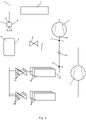
- Fig. 1 is a diagrammatic view of a vapour compression system 1 being operated in accordance with a method according to a first embodiment of the invention.
- the vapour compression system 1 comprises a compressor unit 2, a heat rejecting heat exchanger 3, an ejector 4, a receiver 5, three expansion devices 6 and three evaporators 7 arranged in a refrigerant path.
- the evaporators 7 are arranged fluidly in parallel, and each of the expansion devices 6 supplies refrigerant to one of the evaporators 7.
- a bypass valve 8 interconnects a gaseous outlet 9 of the receiver 5 and an inlet 10 of the compressor unit 2.
- a non-return valve 11 is arranged in the refrigerant path between an outlet 12 of the evaporators 7 and the inlet 10 of the compressor unit 2.
- Refrigerant flowing in the refrigerant path is compressed by the compressor unit 2.
- the compressed refrigerant is supplied to the heat rejecting heat exchanger 3, where heat exchange takes place with the ambient in such a manner that heat is rejected from the refrigerant.
- the refrigerant leaving the heat rejecting heat exchanger 3 is supplied to a primary inlet 13 of the ejector 4.
- the refrigerant undergoes expansion, and is supplied to the receiver 5.
- the liquid part of the refrigerant is separated from the gaseous part of the refrigerant.
- the liquid part of the refrigerant in the receiver 5 is supplied to the expansion devices 6, where it undergoes expansion before being supplied to the respective evaporators 7.
- heat exchange takes place between the refrigerant and the ambient in such a manner that heat is absorbed by the refrigerant, while the liquid part of the refrigerant is at least partly evaporated.
- the refrigerant leaving the evaporators 7 may either be supplied to the inlet 10 of the compressor unit 2, via the non-return valve 11, or it may be supplied to a secondary inlet 14 of the ejector 4.
- a pressure, P 0 of refrigerant leaving the evaporators 7 is measured by means of sensor 15, and a pressure, P suc , of refrigerant entering the compressor unit 2 is measured by means of sensor 16.
- P suc could be obtained in an alternative manner, e.g. by deriving P suc from one or more other measured parameters, e.g. P 0 or a pressure prevailing inside the receiver 5.
- Fig. 2 is a diagrammatic view of a vapour compression system 1 being operated in accordance with a method according to a second embodiment of the invention.
- the vapour compression system 1 is very similar to the vapour compression system 1 of Fig. 1 , and it will therefore not be described in detail here.
- the vapour compression system 1 of Fig. 2 comprises three medium temperature evaporators 7a, corresponding to the evaporators 7 illustrated in Fig. 1 , and three low temperature evaporators 7b, each receiving refrigerant from a separate expansion device 6b.
- the low temperature evaporators 7b are designed to provide a lower cooling temperature than the medium temperature evaporators 7a.
- the pressure prevailing in the low temperature evaporators 7b is also lower than the pressure prevailing in the medium temperature evaporators 7a. Therefore the refrigerant leaving the low temperature evaporators 7b is supplied to a low temperature compressor unit 17, in order to increase the pressure of the refrigerant before it reaches the compressor unit 2.
- the refrigerant leaving the low temperature compressor unit 17 is supplied to the refrigerant path between the non-return valve 11 and the inlet 10 of the compressor unit 2. Thereby this part of the refrigerant path receives a refrigerant supply which is completely independent of the refrigerant flow out of the medium temperature evaporators 7a, and thereby completely decoupled from P 0 . Therefore, in this embodiment there is a particular risk that P suc increases while P 0 remains steady, and the method described above with reference to Fig. 1 is therefore particularly relevant here.
- Fig. 3 is a diagrammatic view of a vapour compression system 1 being operated in accordance with a method according to a third embodiment of the invention.
- the vapour compression system 1 is very similar to the vapour compression system 1 of Fig. 2 , and it will therefore not be described in detail here.
- Fig. 4 is a graph illustrating pressure conditions in a vapour compression system being operated in accordance with a method according to an embodiment of the invention.
- the vapour compression system could, e.g., be one of the vapour compression system shown in Figs. 1-3 .
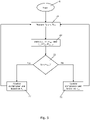
- Fig. 5 is a flow chart illustrating a method according to an embodiment of the invention.
- the process is started at step 18.
- a pressure, P 0 of refrigerant leaving the evaporator and a pressure, P suc , of refrigerant entering the compressor unit are measured.
- P suc or another value being representative for P suc , could be obtained in another manner than by direct measurement, as described in detail above.
- step 21 it is investigated whether ⁇ 0 > ⁇ suc . If this is the case, the process is forwarded to step 22, where the compressor unit is controlled based on P 0 . In the case that step 21 reveals that ⁇ 0 is not larger than ⁇ suc , the process is instead forwarded to step 23, where the compressor unit is controlled based on P suc . From step 22 as well as from step 23, the process is returned to step 19 for new measurements of P 0 and P suc .
Landscapes
- Engineering & Computer Science (AREA)
- Physics & Mathematics (AREA)
- Mechanical Engineering (AREA)
- Thermal Sciences (AREA)
- General Engineering & Computer Science (AREA)
- Devices That Are Associated With Refrigeration Equipment (AREA)
- Air-Conditioning For Vehicles (AREA)
Claims (9)
- Procédé de commande d'un système de compression de vapeur (1), le système de compression de vapeur (1) comprenant une unité de compression (2) comprenant un ou plusieurs compresseurs, un échangeur de chaleur rejetant la chaleur (3), un éjecteur (4), un récepteur (5), au moins un dispositif d'expansion (6) et au moins un évaporateur (7) disposés dans un passage réfrigérant, une sortie de l'échangeur de chaleur rejetant la chaleur étant connectée à une entrée primaire (13) de l'éjecteur (4), une sortie de l'éjecteur (3) étant connectée à une entrée du récepteur (5), et une sortie (12) de l'évaporateur (7) étant connectée à une entrée secondaire (14) de l'éjecteur (4) et à une entrée (10) de l'unité de compression (2), le système de compression de vapeur (1) comprenant en outre une soupape antiretour (11) disposée dans le passage réfrigérant entre la sortie (12) de l'évaporateur (7) et l'entrée (10) de l'unité de compression (2) de manière à ce qu'un flux de réfrigérant depuis la sortie (12) de l'évaporateur (7) vers l'entrée (10) de l'unité de compression (2) soit permis, alors qu'un flux de fluide depuis l'entrée (10) de l'unité de compresseur (2) vers la sortie (12) de l'évaporateur (7) soit empêché, et une sortie de gaz (9) du récepteur (5) étant connectée à l'entrée (10) de l'unité de compresseur (2) par l'intermédiaire d'une soupape de dérivation (8), caractérisé en ce que le procédé comprend les étapes :- de mesure d'une pression P0 de réfrigérant quittant l'évaporateur (7),- d'obtention d'une valeur qui est représentative d'une pression Psuc de réfrigérant entrant dans l'unité de compression (2),- de comparaison des pressions P0 et Psuc à des valeurs de pression de référence respectives P0,ref et Psuc,ref,- dans le cas où ε0 > εsuc, sachant que ε0=P0-P0,ref et εsuc=Psuc-Psuc,ref, commande de l'unité de compression (2) en se basant sur P0, et- dans le cas où εsuc > ε0, commande de l'unité de compression (2) en se basant sur Psuc.
- Procédé selon la revendication 1, dans lequel Psuc,ref est sélectionné de manière à ce que Psuc,ref=P0,ref+ΔPmax, sachant que ΔPmax est une élévation de pression atteignable maximale créée par l'éjecteur (4).
- Procédé selon la revendication 1 ou 2, dans lequel le système de compression de vapeur (1) comprend au moins un évaporateur de température de fluide (7a) et au moins un évaporateur à basse température (7b), et la pression P0 est mesurée à une sortie (12) de l'évaporateur de température de fluide (7a).
- Procédé selon la revendication 3, dans lequel le système de compression de vapeur (1) comprend au moins une unité de compression à basse température (17), et une sortie de l'évaporateur à basse température (7b) est connectée à une entrée de l'unité de compression à basse température (17), et une sortie de l'unité de compression à basse température (17) est connectée à l'entrée (10) de l'unité de compression (2).
- Procédé selon l'une quelconque des revendications précédentes, comprenant en outre l'étape de commande d'une pression régnant à l'intérieur du récepteur (5) en réglant un degré d'ouverture de la vanne de dérivation (8).
- Procédé selon l'une quelconque des revendications précédentes, dans lequel l'étape d'obtention d'une valeur qui est représentative de la pression Psuc comprend la mesure de Psuc.
- Procédé selon l'une quelconque des revendications 1 à 5, dans lequel l'étape d'obtention d'une valeur qui est représentative de la pression Psuc comprend la mesure d'une pression régnant à l'intérieur du récepteur (5) et la dérivation de Psuc de la pression régnant à l'intérieur du récepteur (5).
- Procédé selon l'une quelconque des revendications 1 à 5, dans lequel l'étape d'obtention d'une valeur qui est représentative de la pression Psuc comprend la dérivation de Psuc de P0.
- Procédé selon l'une quelconque des revendications précédentes, dans lequel l'étape de commande de l'unité de compression (2) basée sur P0 comprend la commande de l'unité de compression (2) afin d'obtenir que P0=P0,ref et/ou l'étape de commande de l'unité de compression (2) basée sur Psuc comprend la commande de l'unité de compression (2) afin d'obtenir que Psuc=Psuc,ref.
Priority Applications (5)
| Application Number | Priority Date | Filing Date | Title |
|---|---|---|---|
| PL19199832.7T PL3798533T3 (pl) | 2019-09-26 | 2019-09-26 | Sposób sterowania ciśnieniem ssania układu sprężania pary |
| EP19199832.7A EP3798533B1 (fr) | 2019-09-26 | 2019-09-26 | Procédé de commande de pression d'aspiration d'un système de compression de vapeur |
| US17/609,876 US20220221207A1 (en) | 2019-09-26 | 2020-08-13 | A method for controlling suction pressure of a vapour compression system |
| PCT/EP2020/072723 WO2021058193A1 (fr) | 2019-09-26 | 2020-08-13 | Procédé de régulation de la pression d'aspiration d'un système de compression de vapeur |
| CN202080035300.7A CN113825960B (zh) | 2019-09-26 | 2020-08-13 | 用于控制蒸气压缩系统的抽吸压力的方法 |
Applications Claiming Priority (1)
| Application Number | Priority Date | Filing Date | Title |
|---|---|---|---|
| EP19199832.7A EP3798533B1 (fr) | 2019-09-26 | 2019-09-26 | Procédé de commande de pression d'aspiration d'un système de compression de vapeur |
Publications (2)
| Publication Number | Publication Date |
|---|---|
| EP3798533A1 EP3798533A1 (fr) | 2021-03-31 |
| EP3798533B1 true EP3798533B1 (fr) | 2022-04-20 |
Family
ID=68072123
Family Applications (1)
| Application Number | Title | Priority Date | Filing Date |
|---|---|---|---|
| EP19199832.7A Active EP3798533B1 (fr) | 2019-09-26 | 2019-09-26 | Procédé de commande de pression d'aspiration d'un système de compression de vapeur |
Country Status (5)
| Country | Link |
|---|---|
| US (1) | US20220221207A1 (fr) |
| EP (1) | EP3798533B1 (fr) |
| CN (1) | CN113825960B (fr) |
| PL (1) | PL3798533T3 (fr) |
| WO (1) | WO2021058193A1 (fr) |
Families Citing this family (6)
| Publication number | Priority date | Publication date | Assignee | Title |
|---|---|---|---|---|
| PL3628940T3 (pl) | 2018-09-25 | 2022-08-22 | Danfoss A/S | Sposób sterowania systemem sprężania pary na podstawie szacowanego przepływu |
| PL3628942T3 (pl) | 2018-09-25 | 2021-10-04 | Danfoss A/S | Sposób sterowania układem sprężania pary przy zmniejszonym ciśnieniu ssania |
| IT202100024482A1 (it) * | 2021-09-23 | 2023-03-23 | Carel Ind Spa | Metodo e apparato di regolazione di un impianto frigorifero e relativo impianto frigorifero includente detto apparato |
| EP4155622A1 (fr) * | 2021-09-23 | 2023-03-29 | Carel Industries S.p.A. | Procede et appareil de regulation d'une installation frigorifique et installation frigorifique respective comprenant ledit appareil |
| EP4435346A1 (fr) * | 2023-03-21 | 2024-09-25 | Race SA | Système de refrigération |
| WO2024194746A1 (fr) * | 2023-03-21 | 2024-09-26 | Race Sa | Système de réfrigération |
Family Cites Families (4)
| Publication number | Priority date | Publication date | Assignee | Title |
|---|---|---|---|---|
| WO2016004988A1 (fr) * | 2014-07-09 | 2016-01-14 | Carrier Corporation | Système de réfrigération |
| EP3032192B1 (fr) * | 2014-12-09 | 2020-07-29 | Danfoss A/S | Procédé de commande d'un agencement de soupape dans un système de compression de vapeur |
| EP3098543A1 (fr) | 2015-05-28 | 2016-11-30 | Danfoss A/S | Système de compression de vapeur avec un éjecteur et un clapet de non-retour |
| CN106931675B (zh) * | 2017-04-13 | 2019-11-29 | 广东美的白色家电技术创新中心有限公司 | 喷射式循环系统和空调 |
-
2019
- 2019-09-26 EP EP19199832.7A patent/EP3798533B1/fr active Active
- 2019-09-26 PL PL19199832.7T patent/PL3798533T3/pl unknown
-
2020
- 2020-08-13 CN CN202080035300.7A patent/CN113825960B/zh active Active
- 2020-08-13 US US17/609,876 patent/US20220221207A1/en active Pending
- 2020-08-13 WO PCT/EP2020/072723 patent/WO2021058193A1/fr active Application Filing
Also Published As
| Publication number | Publication date |
|---|---|
| WO2021058193A1 (fr) | 2021-04-01 |
| US20220221207A1 (en) | 2022-07-14 |
| CN113825960B (zh) | 2022-12-23 |
| PL3798533T3 (pl) | 2022-08-08 |
| EP3798533A1 (fr) | 2021-03-31 |
| CN113825960A (zh) | 2021-12-21 |
Similar Documents
| Publication | Publication Date | Title |
|---|---|---|
| EP3798533B1 (fr) | Procédé de commande de pression d'aspiration d'un système de compression de vapeur | |
| US10544971B2 (en) | Method for controlling a vapour compression system with an ejector | |
| US10378796B2 (en) | Method for controlling a valve arrangement in a vapour compression system | |
| EP3365618B1 (fr) | Procédé de commande de système à compression de vapeur à valeur de réglage variable de pression de récepteur | |
| US10941964B2 (en) | Method for operating a vapour compression system with a receiver | |
| CN106574813B (zh) | 用于控制可变能力喷射器单元的方法 | |
| EP3545243B1 (fr) | Procédé de commande d'un système de compression de vapeur pendant un dysfonctionnement de soupape de dérivation de gaz | |
| EP3545242B1 (fr) | Procédé de commande d'un système de compression de vapeur lors d'un dysfonctionnement de soupape de dérivation de gaz | |
| CN118293583B (zh) | 热泵系统及热泵系统的控制方法 | |
| US11959676B2 (en) | Method for controlling a vapour compression system at a reduced suction pressure | |
| CN112513542B (zh) | 用于基于预估流量来控制蒸气压缩系统的方法 |
Legal Events
| Date | Code | Title | Description |
|---|---|---|---|
| PUAI | Public reference made under article 153(3) epc to a published international application that has entered the european phase |
Free format text: ORIGINAL CODE: 0009012 |
|
| STAA | Information on the status of an ep patent application or granted ep patent |
Free format text: STATUS: THE APPLICATION HAS BEEN PUBLISHED |
|
| AK | Designated contracting states |
Kind code of ref document: A1 Designated state(s): AL AT BE BG CH CY CZ DE DK EE ES FI FR GB GR HR HU IE IS IT LI LT LU LV MC MK MT NL NO PL PT RO RS SE SI SK SM TR |
|
| AX | Request for extension of the european patent |
Extension state: BA ME |
|
| STAA | Information on the status of an ep patent application or granted ep patent |
Free format text: STATUS: REQUEST FOR EXAMINATION WAS MADE |
|
| 17P | Request for examination filed |
Effective date: 20210503 |
|
| RBV | Designated contracting states (corrected) |
Designated state(s): AL AT BE BG CH CY CZ DE DK EE ES FI FR GB GR HR HU IE IS IT LI LT LU LV MC MK MT NL NO PL PT RO RS SE SI SK SM TR |
|
| TPAC | Observations filed by third parties |
Free format text: ORIGINAL CODE: EPIDOSNTIPA |
|
| GRAP | Despatch of communication of intention to grant a patent |
Free format text: ORIGINAL CODE: EPIDOSNIGR1 |
|
| STAA | Information on the status of an ep patent application or granted ep patent |
Free format text: STATUS: GRANT OF PATENT IS INTENDED |
|
| INTG | Intention to grant announced |
Effective date: 20211216 |
|
| RIN1 | Information on inventor provided before grant (corrected) |
Inventor name: PRINS, JAN Inventor name: LARSEN, LARS FINN SLOTH |
|
| GRAS | Grant fee paid |
Free format text: ORIGINAL CODE: EPIDOSNIGR3 |
|
| GRAA | (expected) grant |
Free format text: ORIGINAL CODE: 0009210 |
|
| STAA | Information on the status of an ep patent application or granted ep patent |
Free format text: STATUS: THE PATENT HAS BEEN GRANTED |
|
| AK | Designated contracting states |
Kind code of ref document: B1 Designated state(s): AL AT BE BG CH CY CZ DE DK EE ES FI FR GB GR HR HU IE IS IT LI LT LU LV MC MK MT NL NO PL PT RO RS SE SI SK SM TR |
|
| REG | Reference to a national code |
Ref country code: GB Ref legal event code: FG4D |
|
| REG | Reference to a national code |
Ref country code: CH Ref legal event code: EP |
|
| REG | Reference to a national code |
Ref country code: IE Ref legal event code: FG4D |
|
| REG | Reference to a national code |
Ref country code: DE Ref legal event code: R096 Ref document number: 602019013857 Country of ref document: DE |
|
| REG | Reference to a national code |
Ref country code: AT Ref legal event code: REF Ref document number: 1485425 Country of ref document: AT Kind code of ref document: T Effective date: 20220515 |
|
| REG | Reference to a national code |
Ref country code: LT Ref legal event code: MG9D |
|
| REG | Reference to a national code |
Ref country code: NL Ref legal event code: MP Effective date: 20220420 |
|
| REG | Reference to a national code |
Ref country code: AT Ref legal event code: MK05 Ref document number: 1485425 Country of ref document: AT Kind code of ref document: T Effective date: 20220420 |
|
| PG25 | Lapsed in a contracting state [announced via postgrant information from national office to epo] |
Ref country code: NL Free format text: LAPSE BECAUSE OF FAILURE TO SUBMIT A TRANSLATION OF THE DESCRIPTION OR TO PAY THE FEE WITHIN THE PRESCRIBED TIME-LIMIT Effective date: 20220420 |
|
| PG25 | Lapsed in a contracting state [announced via postgrant information from national office to epo] |
Ref country code: SE Free format text: LAPSE BECAUSE OF FAILURE TO SUBMIT A TRANSLATION OF THE DESCRIPTION OR TO PAY THE FEE WITHIN THE PRESCRIBED TIME-LIMIT Effective date: 20220420 Ref country code: PT Free format text: LAPSE BECAUSE OF FAILURE TO SUBMIT A TRANSLATION OF THE DESCRIPTION OR TO PAY THE FEE WITHIN THE PRESCRIBED TIME-LIMIT Effective date: 20220822 Ref country code: NO Free format text: LAPSE BECAUSE OF FAILURE TO SUBMIT A TRANSLATION OF THE DESCRIPTION OR TO PAY THE FEE WITHIN THE PRESCRIBED TIME-LIMIT Effective date: 20220720 Ref country code: LT Free format text: LAPSE BECAUSE OF FAILURE TO SUBMIT A TRANSLATION OF THE DESCRIPTION OR TO PAY THE FEE WITHIN THE PRESCRIBED TIME-LIMIT Effective date: 20220420 Ref country code: HR Free format text: LAPSE BECAUSE OF FAILURE TO SUBMIT A TRANSLATION OF THE DESCRIPTION OR TO PAY THE FEE WITHIN THE PRESCRIBED TIME-LIMIT Effective date: 20220420 Ref country code: GR Free format text: LAPSE BECAUSE OF FAILURE TO SUBMIT A TRANSLATION OF THE DESCRIPTION OR TO PAY THE FEE WITHIN THE PRESCRIBED TIME-LIMIT Effective date: 20220721 Ref country code: FI Free format text: LAPSE BECAUSE OF FAILURE TO SUBMIT A TRANSLATION OF THE DESCRIPTION OR TO PAY THE FEE WITHIN THE PRESCRIBED TIME-LIMIT Effective date: 20220420 Ref country code: ES Free format text: LAPSE BECAUSE OF FAILURE TO SUBMIT A TRANSLATION OF THE DESCRIPTION OR TO PAY THE FEE WITHIN THE PRESCRIBED TIME-LIMIT Effective date: 20220420 Ref country code: BG Free format text: LAPSE BECAUSE OF FAILURE TO SUBMIT A TRANSLATION OF THE DESCRIPTION OR TO PAY THE FEE WITHIN THE PRESCRIBED TIME-LIMIT Effective date: 20220720 Ref country code: AT Free format text: LAPSE BECAUSE OF FAILURE TO SUBMIT A TRANSLATION OF THE DESCRIPTION OR TO PAY THE FEE WITHIN THE PRESCRIBED TIME-LIMIT Effective date: 20220420 |
|
| PG25 | Lapsed in a contracting state [announced via postgrant information from national office to epo] |
Ref country code: RS Free format text: LAPSE BECAUSE OF FAILURE TO SUBMIT A TRANSLATION OF THE DESCRIPTION OR TO PAY THE FEE WITHIN THE PRESCRIBED TIME-LIMIT Effective date: 20220420 Ref country code: LV Free format text: LAPSE BECAUSE OF FAILURE TO SUBMIT A TRANSLATION OF THE DESCRIPTION OR TO PAY THE FEE WITHIN THE PRESCRIBED TIME-LIMIT Effective date: 20220420 Ref country code: IS Free format text: LAPSE BECAUSE OF FAILURE TO SUBMIT A TRANSLATION OF THE DESCRIPTION OR TO PAY THE FEE WITHIN THE PRESCRIBED TIME-LIMIT Effective date: 20220820 |
|
| REG | Reference to a national code |
Ref country code: DE Ref legal event code: R097 Ref document number: 602019013857 Country of ref document: DE |
|
| PG25 | Lapsed in a contracting state [announced via postgrant information from national office to epo] |
Ref country code: SM Free format text: LAPSE BECAUSE OF FAILURE TO SUBMIT A TRANSLATION OF THE DESCRIPTION OR TO PAY THE FEE WITHIN THE PRESCRIBED TIME-LIMIT Effective date: 20220420 Ref country code: SK Free format text: LAPSE BECAUSE OF FAILURE TO SUBMIT A TRANSLATION OF THE DESCRIPTION OR TO PAY THE FEE WITHIN THE PRESCRIBED TIME-LIMIT Effective date: 20220420 Ref country code: RO Free format text: LAPSE BECAUSE OF FAILURE TO SUBMIT A TRANSLATION OF THE DESCRIPTION OR TO PAY THE FEE WITHIN THE PRESCRIBED TIME-LIMIT Effective date: 20220420 Ref country code: EE Free format text: LAPSE BECAUSE OF FAILURE TO SUBMIT A TRANSLATION OF THE DESCRIPTION OR TO PAY THE FEE WITHIN THE PRESCRIBED TIME-LIMIT Effective date: 20220420 Ref country code: DK Free format text: LAPSE BECAUSE OF FAILURE TO SUBMIT A TRANSLATION OF THE DESCRIPTION OR TO PAY THE FEE WITHIN THE PRESCRIBED TIME-LIMIT Effective date: 20220420 Ref country code: CZ Free format text: LAPSE BECAUSE OF FAILURE TO SUBMIT A TRANSLATION OF THE DESCRIPTION OR TO PAY THE FEE WITHIN THE PRESCRIBED TIME-LIMIT Effective date: 20220420 |
|
| PLBE | No opposition filed within time limit |
Free format text: ORIGINAL CODE: 0009261 |
|
| STAA | Information on the status of an ep patent application or granted ep patent |
Free format text: STATUS: NO OPPOSITION FILED WITHIN TIME LIMIT |
|
| 26N | No opposition filed |
Effective date: 20230123 |
|
| PG25 | Lapsed in a contracting state [announced via postgrant information from national office to epo] |
Ref country code: AL Free format text: LAPSE BECAUSE OF FAILURE TO SUBMIT A TRANSLATION OF THE DESCRIPTION OR TO PAY THE FEE WITHIN THE PRESCRIBED TIME-LIMIT Effective date: 20220420 |
|
| PG25 | Lapsed in a contracting state [announced via postgrant information from national office to epo] |
Ref country code: MC Free format text: LAPSE BECAUSE OF FAILURE TO SUBMIT A TRANSLATION OF THE DESCRIPTION OR TO PAY THE FEE WITHIN THE PRESCRIBED TIME-LIMIT Effective date: 20220420 |
|
| REG | Reference to a national code |
Ref country code: CH Ref legal event code: PL |
|
| REG | Reference to a national code |
Ref country code: BE Ref legal event code: MM Effective date: 20220930 |
|
| PG25 | Lapsed in a contracting state [announced via postgrant information from national office to epo] |
Ref country code: SI Free format text: LAPSE BECAUSE OF FAILURE TO SUBMIT A TRANSLATION OF THE DESCRIPTION OR TO PAY THE FEE WITHIN THE PRESCRIBED TIME-LIMIT Effective date: 20220420 |
|
| PG25 | Lapsed in a contracting state [announced via postgrant information from national office to epo] |
Ref country code: LU Free format text: LAPSE BECAUSE OF NON-PAYMENT OF DUE FEES Effective date: 20220926 |
|
| P01 | Opt-out of the competence of the unified patent court (upc) registered |
Effective date: 20230617 |
|
| PG25 | Lapsed in a contracting state [announced via postgrant information from national office to epo] |
Ref country code: LI Free format text: LAPSE BECAUSE OF NON-PAYMENT OF DUE FEES Effective date: 20220930 Ref country code: IE Free format text: LAPSE BECAUSE OF NON-PAYMENT OF DUE FEES Effective date: 20220926 Ref country code: CH Free format text: LAPSE BECAUSE OF NON-PAYMENT OF DUE FEES Effective date: 20220930 |
|
| PG25 | Lapsed in a contracting state [announced via postgrant information from national office to epo] |
Ref country code: BE Free format text: LAPSE BECAUSE OF NON-PAYMENT OF DUE FEES Effective date: 20220930 |
|
| PGFP | Annual fee paid to national office [announced via postgrant information from national office to epo] |
Ref country code: TR Payment date: 20230925 Year of fee payment: 5 Ref country code: IT Payment date: 20230810 Year of fee payment: 5 |
|
| PGFP | Annual fee paid to national office [announced via postgrant information from national office to epo] |
Ref country code: PL Payment date: 20230816 Year of fee payment: 5 |
|
| PG25 | Lapsed in a contracting state [announced via postgrant information from national office to epo] |
Ref country code: CY Free format text: LAPSE BECAUSE OF FAILURE TO SUBMIT A TRANSLATION OF THE DESCRIPTION OR TO PAY THE FEE WITHIN THE PRESCRIBED TIME-LIMIT Effective date: 20220420 |
|
| GBPC | Gb: european patent ceased through non-payment of renewal fee |
Effective date: 20230926 |
|
| PG25 | Lapsed in a contracting state [announced via postgrant information from national office to epo] |
Ref country code: MK Free format text: LAPSE BECAUSE OF FAILURE TO SUBMIT A TRANSLATION OF THE DESCRIPTION OR TO PAY THE FEE WITHIN THE PRESCRIBED TIME-LIMIT Effective date: 20220420 Ref country code: HU Free format text: LAPSE BECAUSE OF FAILURE TO SUBMIT A TRANSLATION OF THE DESCRIPTION OR TO PAY THE FEE WITHIN THE PRESCRIBED TIME-LIMIT; INVALID AB INITIO Effective date: 20190926 |
|
| PG25 | Lapsed in a contracting state [announced via postgrant information from national office to epo] |
Ref country code: GB Free format text: LAPSE BECAUSE OF NON-PAYMENT OF DUE FEES Effective date: 20230926 |
|
| PG25 | Lapsed in a contracting state [announced via postgrant information from national office to epo] |
Ref country code: GB Free format text: LAPSE BECAUSE OF NON-PAYMENT OF DUE FEES Effective date: 20230926 |
|
| PG25 | Lapsed in a contracting state [announced via postgrant information from national office to epo] |
Ref country code: MT Free format text: LAPSE BECAUSE OF FAILURE TO SUBMIT A TRANSLATION OF THE DESCRIPTION OR TO PAY THE FEE WITHIN THE PRESCRIBED TIME-LIMIT Effective date: 20220420 |
|
| PGFP | Annual fee paid to national office [announced via postgrant information from national office to epo] |
Ref country code: DE Payment date: 20240806 Year of fee payment: 6 |
|
| PGFP | Annual fee paid to national office [announced via postgrant information from national office to epo] |
Ref country code: FR Payment date: 20240821 Year of fee payment: 6 |