EP3628607B1 - Kasten aus formvlies - Google Patents
Kasten aus formvlies Download PDFInfo
- Publication number
- EP3628607B1 EP3628607B1 EP19184958.7A EP19184958A EP3628607B1 EP 3628607 B1 EP3628607 B1 EP 3628607B1 EP 19184958 A EP19184958 A EP 19184958A EP 3628607 B1 EP3628607 B1 EP 3628607B1
- Authority
- EP
- European Patent Office
- Prior art keywords
- box
- bracket
- lateral walls
- web
- base
- Prior art date
- Legal status (The legal status is an assumption and is not a legal conclusion. Google has not performed a legal analysis and makes no representation as to the accuracy of the status listed.)
- Active
Links
Images


Classifications
-
- B—PERFORMING OPERATIONS; TRANSPORTING
- B65—CONVEYING; PACKING; STORING; HANDLING THIN OR FILAMENTARY MATERIAL
- B65D—CONTAINERS FOR STORAGE OR TRANSPORT OF ARTICLES OR MATERIALS, e.g. BAGS, BARRELS, BOTTLES, BOXES, CANS, CARTONS, CRATES, DRUMS, JARS, TANKS, HOPPERS, FORWARDING CONTAINERS; ACCESSORIES, CLOSURES, OR FITTINGS THEREFOR; PACKAGING ELEMENTS; PACKAGES
- B65D37/00—Portable flexible containers not otherwise provided for
-
- B—PERFORMING OPERATIONS; TRANSPORTING
- B65—CONVEYING; PACKING; STORING; HANDLING THIN OR FILAMENTARY MATERIAL
- B65D—CONTAINERS FOR STORAGE OR TRANSPORT OF ARTICLES OR MATERIALS, e.g. BAGS, BARRELS, BOTTLES, BOXES, CANS, CARTONS, CRATES, DRUMS, JARS, TANKS, HOPPERS, FORWARDING CONTAINERS; ACCESSORIES, CLOSURES, OR FITTINGS THEREFOR; PACKAGING ELEMENTS; PACKAGES
- B65D15/00—Containers having bodies formed by interconnecting or uniting two or more rigid, or substantially rigid, sections made of different materials
- B65D15/22—Containers having bodies formed by interconnecting or uniting two or more rigid, or substantially rigid, sections made of different materials of polygonal cross-section
Definitions
- the invention relates to a box made of molded fleece, in particular made of felt, with a box bottom and with several box side walls.
- the box can be used, for example, to store items in a work environment.
- Such a box made of felt is for example by EP 3 216 713 A1 known.
- Formed fleece are molded parts made of fibers in which a bond is created between the fibers through the processing process and the fleece is given the desired shape. It is therefore a flat textile structure.
- Formed fleece can consist, for example, of plastic fibers, wood fibers, other plant fibers, natural fibers such as wool fibers or even animal hair.
- Felt is such a form fleece, which often consists of wool fibers.
- a fleece consists of tangled and irregularly intertwined fibers.
- the shaped fleece of the box according to the invention is preferably felt, more preferably wool felt.
- the present invention is based on the object of improving a box of the type mentioned at the outset with regard to stability, dimensional stability, aesthetic value of the appearance, etc.
- a bracket made of a more dimensionally stable material than molded fleece which is attached or pushed onto two opposing box side walls, surrounds the box bottom and the two opposing box side walls on the outside and rests flatly on them.
- the bracket is particularly preferably U-shaped and the box is designed as a rectangular box.
- the bracket which is made, for example, of metal or wood, encompasses the box made of flexible or pliable molded fleece and thereby gives the box more stability.
- Form fleece has the special feature that it has a pleasant feel and offers many design options in terms of color.
- These advantages of molded fleece are complemented by the stability of the bracket, so that the resulting box has the pleasant feel of molded fleece, for example felt, and is stable.
- the contrast between the molded fleece and the bracket also leads to an attractive and high-quality appearance of the box.
- the bracket can be plugged onto the two opposite box side walls, for example, from below or pushed on from the side, or the box can be inserted into the bracket from above or pushed onto the side. If necessary, the bracket can be removed from the box again, ie the bracket is releasably connected to the box.
- the box bottom and / or the two opposite box side walls each have an outside recess in which the bracket is sunk.
- the bracket can, for example, be flush with the outside of the box, which overall leads to a flat outside surface of the box. A precisely fitting recess prevents the bracket from slipping sideways on the box.
- the box preferably has a lid, preferably made of molded fleece, to cover the open top of the box.
- the box bottom has a bottom slot and the bracket has a web protruding from the bottom leg.
- the bracket When the bracket is slipped onto the opposite box side walls from below, the web engages through the bottom slot, whereby the bracket is fixed in the box bottom.
- the web is advantageously spaced from the two side legs of the bracket by the wall thickness of the box side walls. When the bracket engages around the box, this gap is filled or closed by the two opposite box side walls so that the web forms a continuous partition inside the box.
- the web stands tall over the box side walls and can be designed as a handle, in particular provided with a handle opening.
- the box can advantageously have a cover with a slot through which the web extends when the top side of the box is covered, whereby the cover is fixed to the bracket and thus to the box.
- the web is at most as high as the side walls, in order to enable boxes to be stacked on top of one another, for example.
- the two side legs of the bracket are particularly preferably bent inward at their free bracket ends, in particular at a distance corresponding to the wall thickness of the two opposite box side walls, to grip around the upper edge of the opposite box side walls and thereby fix the bracket to the box side walls.
- the two box side walls lying opposite one another have incisions which in particular extend at right angles from the box bottom to the upper edge of the box side walls. This enables the box, which is still without a bracket, to be unfolded and several boxes that have been folded apart can be stacked one inside the other to save space. In the assembled state, the incisions are closed and covered by the bracket.
- the box bottom preferably has a shoulder running around the bottom, which extends inwards to at least the level of the inside of the box side walls, in order to enable boxes to be stably stacked on top of one another.
- the box 1 is stabilized by a U-shaped bracket 5 made of metal, which is pushed or pushed onto two opposite box side walls 3 from below.
- the bracket 5 surrounds the box bottom 2 and the two box side walls 3 on the outside and rests flatly on them.
- the (middle) bottom leg of the U-shaped bracket 5 is labeled 5a and the two (outer) side legs are labeled 5b .
- the bracket width is almost the entire width of the box side walls 3.
- the box bottom 2 and the two opposite box side walls 3 each have a circumferential recess 6 on the outside, in which the bracket 5 is sunk.
- the side legs 5b of the bracket 5 are as high as the box side walls 3 and, at their free ends 7, are each approximately 180 ° U-shaped inwards in one of the wall thicknesses of the box side walls 3 corresponding distance bent.
- the bent free ends 7 are suspended from the upper edge 8 of the box side walls 3 and clamped therein, as a result of which the bracket 5 is fixed on the box 1.
- the two box side walls 3 opposite one another each have an incision 11 which extends from the box bottom 2 to the upper edge 8 of the box side walls 3.
- the incision 11 runs centrally in the box side wall 3 and at right angles to the box bottom 2. As in FIG Fig. 3 As shown, these incisions 11 allow the box 1, which is still without a bracket, to be unfolded by opening the incisions 11 and a space-saving stacking of several unfolded boxes 1 in one another open up again.
- Box 1 is only about half as high as in the Figs. 1 and 2
- the box bottom 2 has a bottom slot 12 and the bracket 5 has a web 13 protruding from the bottom leg 5a to over the side legs 5b.
- the web 13 is spaced from the two side legs 5b of the bracket 5 by the wall thickness of the two box side walls 3 lying opposite one another.
- the web 13 stands higher than the box side walls 3, 4 and has a handle opening 14 in the protruding area.
- the web 13 engages through the bottom slot 12, whereby the bracket 5 is fixed in the box bottom 2.
- the gap between the side legs 5b and the web 13 is filled or closed by the two box side walls 3, so that the web 13 forms a continuous partition inside the box 1.
- the top of the box, which is open at the top, is covered with a cover 15 made of molded fleece, which has a cover slot 16 .
- the web 13 engages through the cover slot 16 through, whereby the cover 15 is fixed to the box 1.
- the handle opening 14 is then located above the cover 15.
- Fig. 4 In distinction to Fig. 4 is in the Figs. 5a, 5b the web is at most as high as the box side walls 3 and has no handle opening.
- the web 13 serves here as a longitudinal element of a compartment division, onto which transverse elements 17 are then subsequently attached for a fan-like division.
- the bracket 5 is designed as a double U-bracket in order to receive and stabilize two boxes 1 side by side.
- the boxes 1 can be covered with a lid 15.
- the bracket 5 is designed as a hanging bracket with two side legs 5b of different lengths.
- the longer side leg is bent outwards in a U-shape by approx. 180 ° in order to form a downwardly open hanging groove with which the bracket 5 can be hung on an upper edge, e.g. on the upper edge of a desk partition.
- the shorter side limb can be bent inwards in a U-shape by approximately 180 ° in order to secure the box side wall 3 received therein from being unhinged.
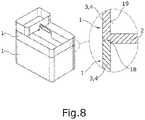
- Fig. 8 several boxes 1 are stacked on top of one another.
- the box bottom 2 of the boxes 1 has a recessed shoulder 18 that runs around the bottom and extends inward to the level of the inside 19 of the box side walls 3, 4.
- With the circumferential shoulder 18 of the respective upper box 1 is placed on the upper edge 8 of the box side walls 3, 4 of the respective lower box 1.
Landscapes
- Engineering & Computer Science (AREA)
- Mechanical Engineering (AREA)
- Details Of Rigid Or Semi-Rigid Containers (AREA)
- Purses, Travelling Bags, Baskets, Or Suitcases (AREA)
- Stackable Containers (AREA)
Description
- Die Erfindung betrifft einen Kasten aus Formvlies, insbesondere aus Filz, mit einem Kastenboden und mit mehreren Kastenseitenwänden. Der Kasten kann beispielsweise zum Aufbewahren von Gegenständen in einer Arbeitsumgebung verwendet werden.
- Ein derartiger Kasten aus Filz ist beispielsweise durch die
EP 3 216 713 A1 bekannt geworden. - Formvlies sind Formteile aus Fasern, bei denen durch den Bearbeitungsprozess eine Bindung zwischen den Fasern hergestellt wird und dem Vlies die gewünschte Form gegeben wird. Es handelt sich also um ein textiles Flächengebilde. Formvlies kann beispielsweise aus Kunststofffasern, Holzfasern, anderen Pflanzenfasern, Naturfasern wie z.B. Wollfasern oder sogar tierischen Haaren, bestehen. Filz ist ein solches Formvlies, das oft aus Wollfasern besteht. Allgemein besteht ein Vlies aus wirren und unregelmäßig verschlungenen Fasern. Bevorzugt ist das Formvlies des erfindungsgemäßen Kastens Filz, weiter bevorzugt Wollfilz.
- Der vorliegenden Erfindung liegt die Aufgabe zugrunde, einen Kasten der eingangs genannten Art hinsichtlich Stabilität, Formstabilität, ästhetische Wertigkeit des Erscheinungsbildes, etc. zu verbessern.
- Diese Aufgabe wird erfindungsgemäß dadurch gelöst, dass ein Bügel aus einem formstabileren Material als Formvlies, der auf zwei einander gegenüberliegende Kastenseitenwände aufgesteckt oder aufgeschoben ist, den Kastenboden und die beiden einander gegenüberliegenden Kastenseitenwände außenseitig umgreift und daran jeweils flächig anliegt. Besonders bevorzugt ist der Bügel U-förmig und der Kasten als Rechteckbox ausgebildet.
- Erfindungsgemäß umgreift der beispielsweise aus Metall oder Holz bestehende Bügel den aus flexiblem bzw. biegsamem Formvlies gebildeten Kasten und verleiht dem Kasten dadurch mehr Stabilität. Formvlies weist insgesamt die Besonderheit auf, dass es eine angenehme Haptik hat und farblich viele Gestaltungsmöglichkeiten bietet. Diese Vorzüge von Formvlies werden durch die Stabilität des Bügels ergänzt, so dass der resultierende Kasten sowohl die angenehme Haptik von Formvlies, z.B. Filz, aufweist als auch stabil ist. Der Kontrast zwischen Formvlies und Bügel führt außerdem zu einem ansprechenden und hochwertigen Erscheinungsbild des Kastens. Der Bügel kann auf die beiden einander gegenüberliegenden Kastenseitenwände beispielsweise von unten aufgesteckt oder seitlich aufgeschoben sein, oder aber der Kasten wird von oben in den Bügel eingesteckt oder seitlich aufgeschoben. Bei Bedarf kann der Bügel wieder vom Kasten abgenommen werden, d.h., der Bügel ist lösbar mit dem Kasten verbunden.
- In einer vorteilhaften Ausführungsform der Erfindung weisen der Kastenboden und/oder die beiden einander gegenüberliegenden Kastenseitenwände jeweils eine außenseitige Ausnehmung auf, in der der Bügel versenkt aufgenommen ist. Dadurch kann der Bügel beispielsweise bündig mit der Kastenaußenseite abschließen, was insgesamt zu einer ebenen Kastenaußenoberfläche führt. Eine passgenaue Ausnehmung verhindert das seitliche Verrutschen des Bügels am Kasten.
- Vorzugsweise weist der Kasten einen Deckel, bevorzugt aus Formvlies, zum Abdecken der offenen Kastenoberseite auf.
- Bei einer besonders bevorzugten Ausführungsform der Erfindung weist der Kastenboden einen Bodenschlitz und der Bügel einen vom Bodenschenkel hochstehenden Steg auf. Beim Aufstecken des Bügels von unten auf die einander gegenüberliegenden Kastenseitenwände greift der Steg durch den Bodenschlitz hindurch, wodurch der Bügel im Kastenboden festgelegt ist. Vorteilhaft ist der Steg von den beiden Seitenschenkeln des Bügels jeweils um die Wandstärke der Kastenseitenwände beabstandet. Dieser Spalt wird, wenn der Bügel den Kasten umgreift, von den beiden einander gegenüberliegenden Kastenseitenwänden ausgefüllt bzw. geschlossen, so dass der Steg eine durchgehende Trennwand innerhalb des Kastens bildet.
- In einer Weiterbildung dieser Ausführungsform steht der Steg über die Kastenseitenwände hoch und kann als ein insbesondere mit einer Grifföffnung versehener Tragegriff ausgebildet sein. Vorteilhaft kann der Kasten einen Deckel mit einem Schlitz aufweisen, durch den bei abgedeckter Kastenoberseite der Steg hindurchgreift, wodurch der Deckel zum Bügel und damit zum Kasten festgelegt ist.
- In einer anderen Weiterbildung ist der Steg höchstens so hoch wie die Seitenwände, um so beispielsweise das Stapeln von Kästen aufeinander zu ermöglichen.
- Besonders bevorzugt sind die beiden Seitenschenkel des Bügels an ihren freien Bügelenden nach innen umgebogen, insbesondere in einem der Wandstärke der beiden einander gegenüberliegenden Kastenseitenwände entsprechenden Abstand, um jeweils die Oberkante der einander gegenüberliegenden Kastenseitenwände zu umgreifen und dadurch den Bügel an den Kastenseitenwänden zu fixieren.
- In einer weiteren bevorzugten Ausführungsform der Erfindung weisen die beiden einander gegenüberliegenden Kastenseitenwände Einschnitte auf, die sich insbesondere rechtwinklig vom Kastenboden bis zur Oberkante der Kastenseitenwände erstrecken. Dies ermöglicht ein Auseinanderklappen des noch bügellosen Kastens und ein platzsparendes Ineinanderstapeln von mehreren auseinandergeklappten Kästen. Im zusammengesteckten Zustand sind die Einschnitte geschlossen und von dem Bügel verdeckt.
- Bevorzugt weist der Kastenboden einen unten umlaufenden Absatz auf, der sich nach innen bis mindestens auf die Höhe der Innenseite der Kastenseitenwände erstreckt, um so ein stabiles Aufeinanderstapeln von Kästen zu ermöglichen. Weitere Vorteile der Erfindung ergeben sich aus der Beschreibung, den Ansprüchen und der Zeichnung. Die gezeigten und beschriebenen Ausführungsformen sind nicht als abschließende Aufzählung zu verstehen, sondern haben vielmehr beispielhaften Charakter für die Schilderung der Erfindung, soweit der Schutzumfang der nachstehenden Ansprüche nicht verlassen wird.
- Es zeigen:
- Fign. 1a, 1b
- eine erste Ausführungsform eines erfindungsgemäßen Kastens aus Formvlies mit einem U-förmigen Metallbügel im noch nicht zusammengesteckten Zustand (
Fig. 1a ) und im zusammengesteckten Zustand (Fig. 1b ); - Fign. 2a, 2b
- eine zweite Ausführungsform eines erfindungsgemäßen Kastens aus Formvlies mit einem U-förmigen Metallbügel im noch nicht zusammengesteckten Zustand (
Fig. 2a ) und im zusammengesteckten Zustand (Fig. 2b ); - Fig. 3
- mehrere ineinander gestapelte Kästen aus Formvlies;
- Fign. 4a-4c
- eine dritte Ausführungsform eines erfindungsgemäßen Kastens aus Formvlies mit einem U-förmigen Metallbügel und einem Deckel im noch nicht zusammengesteckten Zustand (
Fig. 4a ), im zusammengesteckten Zustand (Fig. 4b ) und im abgedeckten Zustand (Fig. 4c ); - Fign. 5a, 5b
- eine vierte Ausführungsform eines erfindungsgemäßen Kastens aus Formvlies mit einem U-förmigen Metallbügel im noch nicht zusammengesteckten Zustand (
Fig. 5a ) und im zusammengesteckten Zustand (Fig. 5b ); - Fign. 6a, 6b
- eine fünfte Ausführungsform eines erfindungsgemäßen Kastens aus Formvlies mit einem doppel-U-förmigen Metallbügel und einem Deckel im noch nicht zusammengesteckten Zustand (
Fig. 6a ) und im zusammengesteckten Zustand (Fig. 6b ); - Fign. 7a, 7b
- eine sechste Ausführungsform eines erfindungsgemäßen Kastens aus Formvlies mit einem U-förmigen Metallbügel im noch nicht zusammengesteckten Zustand (
Fig. 7a ) und im zusammengesteckten Zustand (Fig. 7b ); und - Fig. 8
- mehrere aufeinander gestapelte Kästen.
- Der in
Fig. 1a, 1b als Rechteckbox ausgeführte Kasten 1 aus Formvlies weist einen Kastenboden 2 und vier Kastenseitenwände 3, 4 auf. Der Kasten 1 wird von einem U-förmigen Bügel 5 aus Metall stabilisiert, der auf zwei einander gegenüberliegende Kastenseitenwände 3 von unten aufgesteckt bzw. aufgeschoben ist. Der Bügel 5 umgreift den Kastenboden 2 und die beiden Kastenseitenwände 3 außenseitig und liegt daran jeweils flächig an. Der (mittlere) Bodenschenkel des U-förmigen Bügels 5 ist mit 5a und die beiden (äußeren) Seitenschenkel sind mit 5b bezeichnet. Die Bügelbreite beträgt fast die gesamte Breite der Kastenseitenwände 3. - Der Kastenboden 2 und die beiden zwei einander gegenüberliegenden Kastenseitenwände 3 weisen jeweils eine außenseitig umlaufende Ausnehmung 6 auf, in der der Bügel 5 versenkt aufgenommen ist. Die Seitenschenkel 5b des Bügels 5 sind so hoch wie die Kastenseitenwände 3 und an ihren freien Enden 7 jeweils um ca. 180° U-förmig nach innen in einem der Wandstärke der Kastenseitenwände 3 entsprechenden Abstand umgebogen. Die umgebogenen freien Enden 7 sind im zusammengesteckten Zustand an der Oberkante 8 der Kastenseitenwände 3 eingehängt und darin eingeklemmt, wodurch der Bügel 5 am Kasten 1 fixiert ist.
- In
Fig. 2a, 2b weisen die beiden einander gegenüberliegenden Kastenseitenwände 3 und die Seitenschenkel 5b des Bügels 5 zusätzlich jeweils eine Grifföffnung 9, 10 auf, die dann im zusammengesteckten Zustand eine durchgehende Grifföffnung ausbilden. - Die beiden einander gegenüberliegenden Kastenseitenwände 3 weisen weiterhin jeweils einen Einschnitt 11 auf, der sich vom Kastenboden 2 bis zur Oberkante 8 der Kastenseitenwände 3 erstreckt. Der Einschnitt 11 verläuft mittig in der Kastenseitenwand 3 und rechtwinklig zum Kastenboden 2. Wie in
Fig. 3 gezeigt, ermöglichen diese Einschnitte 11 ein Auseinanderklappen des noch bügellosen Kastens 1 durch Öffnen der Einschnitte 11 und ein platzsparendes Ineinanderstapeln von mehreren auseinandergeklappten Kästen 1. Im zusammengesteckten Zustand verdeckt der Bügel 5 die geschlossenen Einschnitte 11 und verhindert mit seinen eingehängten freien Enden 7, dass sie sich wieder öffnen. - In den
Fign. 4a-4c ist der Kasten 1 nur etwa halb so hoch wie in denFign. 1 und 2 , und zusätzlich weist der Kastenboden 2 einen Bodenschlitz 12 und der Bügel 5 einen vom Bodenschenkel 5a bis über die Seitenschenkel 5b hochstehenden Steg 13 auf. Der Steg 13 ist von den beiden Seitenschenkeln 5b des Bügels 5 jeweils um die Wandstärke der beiden einander gegenüberliegenden Kastenseitenwände 3 beabstandet. Der Steg 13 steht weiter hoch als die Kastenseitenwände 3, 4 und weist im überstehenden Bereich eine Grifföffnung 14 auf. Im zusammengesteckten Zustand (Fig. 4b ) greift der Steg 13 durch den Bodenschlitz 12 hindurch, wodurch der Bügel 5 im Kastenboden 2 festgelegt ist. Der zwischen den Seitenschenkeln 5b und dem Steg 13 jeweils vorhandene Spalt ist von den beiden Kastenseitenwänden 3 ausgefüllt bzw. geschlossen, so dass der Steg 13 eine durchgehende Trennwand innerhalb des Kastens 1 ausbildet. Die oben offene Kastenoberseite ist mit einem Deckel 15 aus Formvlies abgedeckt, der einen Deckelschlitz 16 aufweist. Wie inFig. 4c gezeigt, greift der Steg 13 durch den Deckelschlitz 16 hindurch, wodurch der Deckel 15 am Kasten 1 festgelegt ist. Die Grifföffnung 14 befindet sich dann oberhalb des Deckels 15. - Im Unterscheid zu
Fig. 4 ist in denFign. 5a, 5b der Steg höchstens so hoch wie die Kastenseitenwände 3 und weist keine Grifföffnung auf. Der Steg 13 dient hier als Längselement einer Fachaufteilung, auf das dann nachträglich Querelemente 17 für eine fächerartige Einteilung aufgesteckt sind. - In den
Fign. 6a, 6b ist der Bügel 5 als Doppel-U-Bügel ausgebildet, um darin jeweils zwei Kästen 1 nebeneinander aufzunehmen und zu stabilisieren. Die Kästen 1 können mit einem Deckel 15 abgedeckt werden. - In den
Fign. 7a, 7b ist der Bügel 5 als Hängebügel mit zwei unterschiedlich langen Seitenschenkeln 5b ausgebildet. Der längere Seitenschenkel ist an seinem freien Ende um ca. 180° U-förmig nach außen umgebogen, um dadurch eine nach unten offene Einhängenut auszubilden, mit der der Bügel 5 an einer Oberkante, z.B. an die Oberkante einer Schreibtischtrennwand, eingehängt werden kann. Der kürzere Seitenschenkel kann an seinem freien Ende 7 um ca. 180° U-förmig nach innen umgebogen sein, um die darin aufgenommenen Kastenseitenwand 3 gegen Aushängen zu sichern. - In
Fig. 8 sind mehrere Kästen 1 aufeinander gestapelt. Dazu weist der Kastenboden 2 der Kästen 1 einen unten umlaufenden, rückversetzten Absatz 18 auf, der sich nach innen bis auf die Höhe der Innenseite 19 der Kastenseitenwände 3, 4 erstreckt. Mit dem umlaufenden Absatz 18 ist der jeweils obere Kasten 1 auf die Oberkante 8 der Kastenseitenwände 3, 4 des jeweils unteren Kastens 1 aufgesetzt.
Claims (12)
- Kasten (1) aus Formvlies, insbesondere aus Filz, mit einem Kastenboden (2) und mit mehreren Kastenseitenwänden (3, 4),
dadurch gekennzeichnet,
dass ein, insbesondere U-förmiger, Bügel (5) aus einem formstabileren Material als Formvlies, der auf zwei einander gegenüberliegende Kastenseitenwände (3) aufgesteckt oder aufgeschoben ist, den Kastenboden (2) und die beiden einander gegenüberliegenden Kastenseitenwände (3) außenseitig umgreift und daran jeweils flächig anliegt. - Kasten nach Anspruch 1, dadurch gekennzeichnet, dass der Kastenboden (2) und/oder die beiden einander gegenüberliegenden Kastenseitenwände (3) jeweils eine außenseitige Ausnehmung (6) aufweisen, in der der Bügel (5) versenkt aufgenommen ist.
- Kasten nach Anspruch 1 oder 2, gekennzeichnet durch einen Deckel (15), bevorzugt aus Formvlies, zum Abdecken der offenen Kastenoberseite.
- Kasten nach einem der vorhergehenden Ansprüche, dadurch gekennzeichnet, dass der Kastenboden (2) einen Bodenschlitz (12) und der Bügel (5) einen vom Bodenschenkel (5a) des Bügels (5) hochstehenden Steg (13) aufweist, der durch den Bodenschlitz (12) hindurchgreift.
- Kasten nach Anspruch 4, dadurch gekennzeichnet, dass der Steg (13) von den beiden Seitenschenkeln (5b) des Bügels (5) jeweils um die Wandstärke der beiden einander gegenüberliegenden Kastenseitenwände (3) beabstandet ist.
- Kasten nach Anspruch 4 oder 5, dadurch gekennzeichnet, dass der Steg (13) über die Kastenseitenwände (3, 4) hochsteht.
- Kasten nach Anspruch 6, dadurch gekennzeichnet, dass ein Deckel (15), bevorzugt aus Formvlies, zum Abdecken der offenen Kastenoberseite einen Deckelschlitz (16) aufweist, durch den bei abgedeckter Kastenoberseite der Steg (13) hindurchgreift.
- Kasten nach Anspruch 4 oder 5, dadurch gekennzeichnet, dass der Steg (13) höchstens so hoch wie die Kastenseitenwände (3, 4) ist.
- Kasten nach einem der Ansprüche 4 bis 8, dadurch gekennzeichnet, dass der Steg als ein insbesondere mit einer Grifföffnung (14) versehener Tragegriff (13) ausgebildet ist.
- Kasten nach einem der vorhergehenden Ansprüche, dadurch gekennzeichnet, dass die beiden Seitenschenkel (5b) des Bügels (5) an ihren freien Enden (7) jeweils nach innen umgebogen sind, insbesondere in einem der Wandstärke der beiden einander gegenüberliegenden Kastenseitenwände (3) entsprechenden Abstand, um jeweils die Oberkante (8) der einander gegenüberliegenden Kastenseitenwände (3) zu umgreifen.
- Kasten nach einem der vorhergehenden Ansprüche, dadurch gekennzeichnet, dass die beiden einander gegenüberliegenden Kastenseitenwände (3) Einschnitte (11) aufweisen, die sich vom Kastenboden (2) bis zur Oberkante (8) der Kastenseitenwände (3) erstrecken.
- Kasten nach einem der vorhergehenden Ansprüche, dadurch gekennzeichnet, dass der Kastenboden (2) einen unten umlaufenden Absatz (18) aufweist, der sich nach innen bis mindestens auf die Höhe der Innenseite der Kastenseitenwände (3, 4) erstreckt.
Priority Applications (1)
| Application Number | Priority Date | Filing Date | Title |
|---|---|---|---|
| PL19184958T PL3628607T3 (pl) | 2018-09-26 | 2019-07-08 | Skrzynka z włókniny formowanej |
Applications Claiming Priority (1)
| Application Number | Priority Date | Filing Date | Title |
|---|---|---|---|
| DE202018105525.9U DE202018105525U1 (de) | 2018-09-26 | 2018-09-26 | Kasten aus Formvlies |
Publications (2)
| Publication Number | Publication Date |
|---|---|
| EP3628607A1 EP3628607A1 (de) | 2020-04-01 |
| EP3628607B1 true EP3628607B1 (de) | 2021-02-17 |
Family
ID=63962837
Family Applications (1)
| Application Number | Title | Priority Date | Filing Date |
|---|---|---|---|
| EP19184958.7A Active EP3628607B1 (de) | 2018-09-26 | 2019-07-08 | Kasten aus formvlies |
Country Status (3)
| Country | Link |
|---|---|
| EP (1) | EP3628607B1 (de) |
| DE (1) | DE202018105525U1 (de) |
| PL (1) | PL3628607T3 (de) |
Families Citing this family (2)
| Publication number | Priority date | Publication date | Assignee | Title |
|---|---|---|---|---|
| DE102024100957A1 (de) * | 2024-01-12 | 2025-07-17 | "Durable" Hunke & Jochheim Gmbh & Co. Kommanditgesellschaft | Einrichtungsgegenstand |
| DE102024100962A1 (de) * | 2024-01-12 | 2025-07-17 | "Durable" Hunke & Jochheim Gmbh & Co. Kommanditgesellschaft | Einrichtungsgegenstand |
Family Cites Families (2)
| Publication number | Priority date | Publication date | Assignee | Title |
|---|---|---|---|---|
| US20170217642A1 (en) * | 2016-02-03 | 2017-08-03 | Tung Fong Textile Co.,Ltd. | Composite Storage Bin |
| DE202016101313U1 (de) | 2016-03-10 | 2016-04-07 | Häfele GmbH & Co KG | Kasten mit Haltebändern |
-
2018
- 2018-09-26 DE DE202018105525.9U patent/DE202018105525U1/de not_active Expired - Lifetime
-
2019
- 2019-07-08 EP EP19184958.7A patent/EP3628607B1/de active Active
- 2019-07-08 PL PL19184958T patent/PL3628607T3/pl unknown
Non-Patent Citations (1)
| Title |
|---|
| None * |
Also Published As
| Publication number | Publication date |
|---|---|
| DE202018105525U1 (de) | 2018-10-04 |
| PL3628607T3 (pl) | 2021-07-05 |
| EP3628607A1 (de) | 2020-04-01 |
Similar Documents
| Publication | Publication Date | Title |
|---|---|---|
| DE69722140T2 (de) | Einstückiges Verpackungselement aus Faserpulpe | |
| EP2883480B1 (de) | Variables Regaldisplay | |
| EP3628607A1 (de) | Kasten aus formvlies | |
| DE202017007407U1 (de) | Verbesserung in Bezug auf Kleiderbügel | |
| DE102016006274B4 (de) | Tier-Fressnapf | |
| DE2819678C2 (de) | Transportkasten aus Kunststoff | |
| WO2019002021A1 (de) | Zubehörkoffer | |
| DE2531883C3 (de) | Kastenförmiger Behälter für Hängeakten etc | |
| DE102015119051A1 (de) | Regalboden und Pappregal | |
| DE102019121142A1 (de) | Bodenträger und Hakenelement für einen Zwischenboden einer faltbaren Box | |
| EP2243724A1 (de) | Wasserdichter Behaelterkoerper, wasserdichter Behaelter sowie Zuschnitt zum Herstellen eines Behaelterkoerpers | |
| DE202012104001U1 (de) | Tisch, insbesondere Schreib- oder Arbeitstisch | |
| WO2018094432A1 (de) | Transportbehälter | |
| DE500979C (de) | Zusammenlegbare Eierschachtel | |
| DE102017130511B4 (de) | Metallregal mit als Stanzbiegeteile gestalteten Seitenwänden | |
| AT288317B (de) | Grundbauteil eines schriftgutbehaelters, insbesondere briefordners, vorordners, terminordners, briefkorbes od. dgl. | |
| DE202016101542U1 (de) | Regal | |
| EP0748601A1 (de) | Kasten mit mindestens zwei übereinander oder nebeneinander angeordneten Schubladenstöcken | |
| DE2107543C3 (de) | Bausatz zur Herstellung einer Anordnung von in Abstand mittels Abstandhaltern übereinander angeordneten Kunststoffkästen | |
| DE60004177T2 (de) | Elektrisches Installationsgerät zum Aufschnappen auf eine Tragschiene | |
| DE202020101592U1 (de) | Blumenkasten | |
| DE1056044B (de) | Traggriff fuer Schachteln | |
| DE754777C (de) | Leichtkiste | |
| EP2241217A2 (de) | Rahmengestell eines Schubkastens | |
| DE20006907U1 (de) | Verpackungskarton für Möbelplatten |
Legal Events
| Date | Code | Title | Description |
|---|---|---|---|
| PUAI | Public reference made under article 153(3) epc to a published international application that has entered the european phase |
Free format text: ORIGINAL CODE: 0009012 |
|
| STAA | Information on the status of an ep patent application or granted ep patent |
Free format text: STATUS: THE APPLICATION HAS BEEN PUBLISHED |
|
| STAA | Information on the status of an ep patent application or granted ep patent |
Free format text: STATUS: REQUEST FOR EXAMINATION WAS MADE |
|
| AK | Designated contracting states |
Kind code of ref document: A1 Designated state(s): AL AT BE BG CH CY CZ DE DK EE ES FI FR GB GR HR HU IE IS IT LI LT LU LV MC MK MT NL NO PL PT RO RS SE SI SK SM TR |
|
| AX | Request for extension of the european patent |
Extension state: BA ME |
|
| 17P | Request for examination filed |
Effective date: 20200305 |
|
| RBV | Designated contracting states (corrected) |
Designated state(s): AL AT BE BG CH CY CZ DE DK EE ES FI FR GB GR HR HU IE IS IT LI LT LU LV MC MK MT NL NO PL PT RO RS SE SI SK SM TR |
|
| GRAP | Despatch of communication of intention to grant a patent |
Free format text: ORIGINAL CODE: EPIDOSNIGR1 |
|
| STAA | Information on the status of an ep patent application or granted ep patent |
Free format text: STATUS: GRANT OF PATENT IS INTENDED |
|
| INTG | Intention to grant announced |
Effective date: 20200930 |
|
| GRAS | Grant fee paid |
Free format text: ORIGINAL CODE: EPIDOSNIGR3 |
|
| GRAA | (expected) grant |
Free format text: ORIGINAL CODE: 0009210 |
|
| STAA | Information on the status of an ep patent application or granted ep patent |
Free format text: STATUS: THE PATENT HAS BEEN GRANTED |
|
| REG | Reference to a national code |
Ref country code: DE Ref legal event code: R082 Ref document number: 502019000806 Country of ref document: DE Representative=s name: KOHLER SCHMID MOEBUS PATENTANWAELTE PARTNERSCH, DE Ref country code: DE Ref legal event code: R081 Ref document number: 502019000806 Country of ref document: DE Owner name: HAEFELE SE & CO KG, DE Free format text: FORMER OWNER: HAEFELE GMBH & CO KG, 72202 NAGOLD, DE |
|
| AK | Designated contracting states |
Kind code of ref document: B1 Designated state(s): AL AT BE BG CH CY CZ DE DK EE ES FI FR GB GR HR HU IE IS IT LI LT LU LV MC MK MT NL NO PL PT RO RS SE SI SK SM TR |
|
| REG | Reference to a national code |
Ref country code: GB Ref legal event code: FG4D Free format text: NOT ENGLISH |
|
| REG | Reference to a national code |
Ref country code: CH Ref legal event code: EP Ref country code: CH Ref legal event code: NV Representative=s name: RIEDERER HASLER AND PARTNER PATENTANWAELTE AG, LI |
|
| REG | Reference to a national code |
Ref country code: DE Ref legal event code: R096 Ref document number: 502019000806 Country of ref document: DE |
|
| RAP2 | Party data changed (patent owner data changed or rights of a patent transferred) |
Owner name: HAEFELE SE & CO KG |
|
| REG | Reference to a national code |
Ref country code: AT Ref legal event code: REF Ref document number: 1361172 Country of ref document: AT Kind code of ref document: T Effective date: 20210315 |
|
| REG | Reference to a national code |
Ref country code: IE Ref legal event code: FG4D Free format text: LANGUAGE OF EP DOCUMENT: GERMAN |
|
| REG | Reference to a national code |
Ref country code: LT Ref legal event code: MG9D |
|
| REG | Reference to a national code |
Ref country code: NL Ref legal event code: MP Effective date: 20210217 |
|
| PG25 | Lapsed in a contracting state [announced via postgrant information from national office to epo] |
Ref country code: NO Free format text: LAPSE BECAUSE OF FAILURE TO SUBMIT A TRANSLATION OF THE DESCRIPTION OR TO PAY THE FEE WITHIN THE PRESCRIBED TIME-LIMIT Effective date: 20210517 Ref country code: PT Free format text: LAPSE BECAUSE OF FAILURE TO SUBMIT A TRANSLATION OF THE DESCRIPTION OR TO PAY THE FEE WITHIN THE PRESCRIBED TIME-LIMIT Effective date: 20210617 Ref country code: LT Free format text: LAPSE BECAUSE OF FAILURE TO SUBMIT A TRANSLATION OF THE DESCRIPTION OR TO PAY THE FEE WITHIN THE PRESCRIBED TIME-LIMIT Effective date: 20210217 Ref country code: FI Free format text: LAPSE BECAUSE OF FAILURE TO SUBMIT A TRANSLATION OF THE DESCRIPTION OR TO PAY THE FEE WITHIN THE PRESCRIBED TIME-LIMIT Effective date: 20210217 Ref country code: GR Free format text: LAPSE BECAUSE OF FAILURE TO SUBMIT A TRANSLATION OF THE DESCRIPTION OR TO PAY THE FEE WITHIN THE PRESCRIBED TIME-LIMIT Effective date: 20210518 Ref country code: BG Free format text: LAPSE BECAUSE OF FAILURE TO SUBMIT A TRANSLATION OF THE DESCRIPTION OR TO PAY THE FEE WITHIN THE PRESCRIBED TIME-LIMIT Effective date: 20210517 Ref country code: HR Free format text: LAPSE BECAUSE OF FAILURE TO SUBMIT A TRANSLATION OF THE DESCRIPTION OR TO PAY THE FEE WITHIN THE PRESCRIBED TIME-LIMIT Effective date: 20210217 |
|
| PG25 | Lapsed in a contracting state [announced via postgrant information from national office to epo] |
Ref country code: LV Free format text: LAPSE BECAUSE OF FAILURE TO SUBMIT A TRANSLATION OF THE DESCRIPTION OR TO PAY THE FEE WITHIN THE PRESCRIBED TIME-LIMIT Effective date: 20210217 Ref country code: NL Free format text: LAPSE BECAUSE OF FAILURE TO SUBMIT A TRANSLATION OF THE DESCRIPTION OR TO PAY THE FEE WITHIN THE PRESCRIBED TIME-LIMIT Effective date: 20210217 Ref country code: SE Free format text: LAPSE BECAUSE OF FAILURE TO SUBMIT A TRANSLATION OF THE DESCRIPTION OR TO PAY THE FEE WITHIN THE PRESCRIBED TIME-LIMIT Effective date: 20210217 Ref country code: RS Free format text: LAPSE BECAUSE OF FAILURE TO SUBMIT A TRANSLATION OF THE DESCRIPTION OR TO PAY THE FEE WITHIN THE PRESCRIBED TIME-LIMIT Effective date: 20210217 |
|
| PG25 | Lapsed in a contracting state [announced via postgrant information from national office to epo] |
Ref country code: IS Free format text: LAPSE BECAUSE OF FAILURE TO SUBMIT A TRANSLATION OF THE DESCRIPTION OR TO PAY THE FEE WITHIN THE PRESCRIBED TIME-LIMIT Effective date: 20210617 |
|
| PG25 | Lapsed in a contracting state [announced via postgrant information from national office to epo] |
Ref country code: EE Free format text: LAPSE BECAUSE OF FAILURE TO SUBMIT A TRANSLATION OF THE DESCRIPTION OR TO PAY THE FEE WITHIN THE PRESCRIBED TIME-LIMIT Effective date: 20210217 Ref country code: CZ Free format text: LAPSE BECAUSE OF FAILURE TO SUBMIT A TRANSLATION OF THE DESCRIPTION OR TO PAY THE FEE WITHIN THE PRESCRIBED TIME-LIMIT Effective date: 20210217 Ref country code: SM Free format text: LAPSE BECAUSE OF FAILURE TO SUBMIT A TRANSLATION OF THE DESCRIPTION OR TO PAY THE FEE WITHIN THE PRESCRIBED TIME-LIMIT Effective date: 20210217 |
|
| REG | Reference to a national code |
Ref country code: DE Ref legal event code: R097 Ref document number: 502019000806 Country of ref document: DE |
|
| PG25 | Lapsed in a contracting state [announced via postgrant information from national office to epo] |
Ref country code: DK Free format text: LAPSE BECAUSE OF FAILURE TO SUBMIT A TRANSLATION OF THE DESCRIPTION OR TO PAY THE FEE WITHIN THE PRESCRIBED TIME-LIMIT Effective date: 20210217 Ref country code: RO Free format text: LAPSE BECAUSE OF FAILURE TO SUBMIT A TRANSLATION OF THE DESCRIPTION OR TO PAY THE FEE WITHIN THE PRESCRIBED TIME-LIMIT Effective date: 20210217 Ref country code: SK Free format text: LAPSE BECAUSE OF FAILURE TO SUBMIT A TRANSLATION OF THE DESCRIPTION OR TO PAY THE FEE WITHIN THE PRESCRIBED TIME-LIMIT Effective date: 20210217 |
|
| PLBE | No opposition filed within time limit |
Free format text: ORIGINAL CODE: 0009261 |
|
| STAA | Information on the status of an ep patent application or granted ep patent |
Free format text: STATUS: NO OPPOSITION FILED WITHIN TIME LIMIT |
|
| 26N | No opposition filed |
Effective date: 20211118 |
|
| PG25 | Lapsed in a contracting state [announced via postgrant information from national office to epo] |
Ref country code: ES Free format text: LAPSE BECAUSE OF FAILURE TO SUBMIT A TRANSLATION OF THE DESCRIPTION OR TO PAY THE FEE WITHIN THE PRESCRIBED TIME-LIMIT Effective date: 20210217 Ref country code: AL Free format text: LAPSE BECAUSE OF FAILURE TO SUBMIT A TRANSLATION OF THE DESCRIPTION OR TO PAY THE FEE WITHIN THE PRESCRIBED TIME-LIMIT Effective date: 20210217 |
|
| PG25 | Lapsed in a contracting state [announced via postgrant information from national office to epo] |
Ref country code: SI Free format text: LAPSE BECAUSE OF FAILURE TO SUBMIT A TRANSLATION OF THE DESCRIPTION OR TO PAY THE FEE WITHIN THE PRESCRIBED TIME-LIMIT Effective date: 20210217 |
|
| PG25 | Lapsed in a contracting state [announced via postgrant information from national office to epo] |
Ref country code: MC Free format text: LAPSE BECAUSE OF FAILURE TO SUBMIT A TRANSLATION OF THE DESCRIPTION OR TO PAY THE FEE WITHIN THE PRESCRIBED TIME-LIMIT Effective date: 20210217 |
|
| REG | Reference to a national code |
Ref country code: BE Ref legal event code: MM Effective date: 20210731 |
|
| PG25 | Lapsed in a contracting state [announced via postgrant information from national office to epo] |
Ref country code: IT Free format text: LAPSE BECAUSE OF FAILURE TO SUBMIT A TRANSLATION OF THE DESCRIPTION OR TO PAY THE FEE WITHIN THE PRESCRIBED TIME-LIMIT Effective date: 20210217 |
|
| PG25 | Lapsed in a contracting state [announced via postgrant information from national office to epo] |
Ref country code: IS Free format text: LAPSE BECAUSE OF FAILURE TO SUBMIT A TRANSLATION OF THE DESCRIPTION OR TO PAY THE FEE WITHIN THE PRESCRIBED TIME-LIMIT Effective date: 20210617 Ref country code: LU Free format text: LAPSE BECAUSE OF NON-PAYMENT OF DUE FEES Effective date: 20210708 Ref country code: FR Free format text: LAPSE BECAUSE OF NON-PAYMENT OF DUE FEES Effective date: 20210731 |
|
| PG25 | Lapsed in a contracting state [announced via postgrant information from national office to epo] |
Ref country code: IE Free format text: LAPSE BECAUSE OF NON-PAYMENT OF DUE FEES Effective date: 20210708 Ref country code: BE Free format text: LAPSE BECAUSE OF NON-PAYMENT OF DUE FEES Effective date: 20210731 |
|
| PG25 | Lapsed in a contracting state [announced via postgrant information from national office to epo] |
Ref country code: CY Free format text: LAPSE BECAUSE OF FAILURE TO SUBMIT A TRANSLATION OF THE DESCRIPTION OR TO PAY THE FEE WITHIN THE PRESCRIBED TIME-LIMIT Effective date: 20210217 |
|
| PG25 | Lapsed in a contracting state [announced via postgrant information from national office to epo] |
Ref country code: HU Free format text: LAPSE BECAUSE OF FAILURE TO SUBMIT A TRANSLATION OF THE DESCRIPTION OR TO PAY THE FEE WITHIN THE PRESCRIBED TIME-LIMIT; INVALID AB INITIO Effective date: 20190708 |
|
| P01 | Opt-out of the competence of the unified patent court (upc) registered |
Effective date: 20230630 |
|
| PGFP | Annual fee paid to national office [announced via postgrant information from national office to epo] |
Ref country code: PL Payment date: 20230428 Year of fee payment: 5 |
|
| PGFP | Annual fee paid to national office [announced via postgrant information from national office to epo] |
Ref country code: CH Payment date: 20230801 Year of fee payment: 5 |
|
| GBPC | Gb: european patent ceased through non-payment of renewal fee |
Effective date: 20230708 |
|
| PG25 | Lapsed in a contracting state [announced via postgrant information from national office to epo] |
Ref country code: MK Free format text: LAPSE BECAUSE OF FAILURE TO SUBMIT A TRANSLATION OF THE DESCRIPTION OR TO PAY THE FEE WITHIN THE PRESCRIBED TIME-LIMIT Effective date: 20210217 Ref country code: GB Free format text: LAPSE BECAUSE OF NON-PAYMENT OF DUE FEES Effective date: 20230708 |
|
| PG25 | Lapsed in a contracting state [announced via postgrant information from national office to epo] |
Ref country code: MT Free format text: LAPSE BECAUSE OF FAILURE TO SUBMIT A TRANSLATION OF THE DESCRIPTION OR TO PAY THE FEE WITHIN THE PRESCRIBED TIME-LIMIT Effective date: 20210217 |
|
| REG | Reference to a national code |
Ref country code: CH Ref legal event code: PL |
|
| PG25 | Lapsed in a contracting state [announced via postgrant information from national office to epo] |
Ref country code: CH Free format text: LAPSE BECAUSE OF NON-PAYMENT OF DUE FEES Effective date: 20240731 |
|
| REG | Reference to a national code |
Ref country code: AT Ref legal event code: MM01 Ref document number: 1361172 Country of ref document: AT Kind code of ref document: T Effective date: 20240708 |
|
| PGFP | Annual fee paid to national office [announced via postgrant information from national office to epo] |
Ref country code: DE Payment date: 20250728 Year of fee payment: 7 |
|
| PG25 | Lapsed in a contracting state [announced via postgrant information from national office to epo] |
Ref country code: AT Free format text: LAPSE BECAUSE OF NON-PAYMENT OF DUE FEES Effective date: 20240708 |
|
| PG25 | Lapsed in a contracting state [announced via postgrant information from national office to epo] |
Ref country code: TR Free format text: LAPSE BECAUSE OF FAILURE TO SUBMIT A TRANSLATION OF THE DESCRIPTION OR TO PAY THE FEE WITHIN THE PRESCRIBED TIME-LIMIT Effective date: 20210217 |
|
| PG25 | Lapsed in a contracting state [announced via postgrant information from national office to epo] |
Ref country code: PL Free format text: LAPSE BECAUSE OF NON-PAYMENT OF DUE FEES Effective date: 20240708 |
|
| PGFP | Annual fee paid to national office [announced via postgrant information from national office to epo] |
Ref country code: AT Payment date: 20260410 Year of fee payment: 5 |