EP3628560B1 - Vorrichtung und verfahren zur spurwechselsteuerung - Google Patents
Vorrichtung und verfahren zur spurwechselsteuerung Download PDFInfo
- Publication number
- EP3628560B1 EP3628560B1 EP18210399.4A EP18210399A EP3628560B1 EP 3628560 B1 EP3628560 B1 EP 3628560B1 EP 18210399 A EP18210399 A EP 18210399A EP 3628560 B1 EP3628560 B1 EP 3628560B1
- Authority
- EP
- European Patent Office
- Prior art keywords
- lane change
- change control
- vehicle
- met
- driver
- Prior art date
- Legal status (The legal status is an assumption and is not a legal conclusion. Google has not performed a legal analysis and makes no representation as to the accuracy of the status listed.)
- Active
Links
Images


Classifications
-
- B—PERFORMING OPERATIONS; TRANSPORTING
- B62—LAND VEHICLES FOR TRAVELLING OTHERWISE THAN ON RAILS
- B62D—MOTOR VEHICLES; TRAILERS
- B62D15/00—Steering not otherwise provided for
- B62D15/02—Steering position indicators ; Steering position determination; Steering aids
- B62D15/025—Active steering aids, e.g. helping the driver by actively influencing the steering system after environment evaluation
- B62D15/0255—Automatic changing of lane, e.g. for passing another vehicle
-
- B—PERFORMING OPERATIONS; TRANSPORTING
- B60—VEHICLES IN GENERAL
- B60W—CONJOINT CONTROL OF VEHICLE SUB-UNITS OF DIFFERENT TYPE OR DIFFERENT FUNCTION; CONTROL SYSTEMS SPECIALLY ADAPTED FOR HYBRID VEHICLES; ROAD VEHICLE DRIVE CONTROL SYSTEMS FOR PURPOSES NOT RELATED TO THE CONTROL OF A PARTICULAR SUB-UNIT
- B60W30/00—Purposes of road vehicle drive control systems not related to the control of a particular sub-unit, e.g. of systems using conjoint control of vehicle sub-units
- B60W30/18—Propelling the vehicle
- B60W30/18009—Propelling the vehicle related to particular drive situations
- B60W30/18163—Lane change; Overtaking manoeuvres
-
- B—PERFORMING OPERATIONS; TRANSPORTING
- B60—VEHICLES IN GENERAL
- B60K—ARRANGEMENT OR MOUNTING OF PROPULSION UNITS OR OF TRANSMISSIONS IN VEHICLES; ARRANGEMENT OR MOUNTING OF PLURAL DIVERSE PRIME-MOVERS IN VEHICLES; AUXILIARY DRIVES FOR VEHICLES; INSTRUMENTATION OR DASHBOARDS FOR VEHICLES; ARRANGEMENTS IN CONNECTION WITH COOLING, AIR INTAKE, GAS EXHAUST OR FUEL SUPPLY OF PROPULSION UNITS IN VEHICLES
- B60K35/00—Instruments specially adapted for vehicles; Arrangement of instruments in or on vehicles
- B60K35/10—Input arrangements, i.e. from user to vehicle, associated with vehicle functions or specially adapted therefor
-
- B—PERFORMING OPERATIONS; TRANSPORTING
- B60—VEHICLES IN GENERAL
- B60W—CONJOINT CONTROL OF VEHICLE SUB-UNITS OF DIFFERENT TYPE OR DIFFERENT FUNCTION; CONTROL SYSTEMS SPECIALLY ADAPTED FOR HYBRID VEHICLES; ROAD VEHICLE DRIVE CONTROL SYSTEMS FOR PURPOSES NOT RELATED TO THE CONTROL OF A PARTICULAR SUB-UNIT
- B60W30/00—Purposes of road vehicle drive control systems not related to the control of a particular sub-unit, e.g. of systems using conjoint control of vehicle sub-units
- B60W30/08—Active safety systems predicting or avoiding probable or impending collision or attempting to minimise its consequences
-
- B—PERFORMING OPERATIONS; TRANSPORTING
- B60—VEHICLES IN GENERAL
- B60W—CONJOINT CONTROL OF VEHICLE SUB-UNITS OF DIFFERENT TYPE OR DIFFERENT FUNCTION; CONTROL SYSTEMS SPECIALLY ADAPTED FOR HYBRID VEHICLES; ROAD VEHICLE DRIVE CONTROL SYSTEMS FOR PURPOSES NOT RELATED TO THE CONTROL OF A PARTICULAR SUB-UNIT
- B60W50/00—Details of control systems for road vehicle drive control not related to the control of a particular sub-unit, e.g. process diagnostic or vehicle driver interfaces
- B60W50/08—Interaction between the driver and the control system
- B60W50/082—Selecting or switching between different modes of propelling
-
- B—PERFORMING OPERATIONS; TRANSPORTING
- B60—VEHICLES IN GENERAL
- B60W—CONJOINT CONTROL OF VEHICLE SUB-UNITS OF DIFFERENT TYPE OR DIFFERENT FUNCTION; CONTROL SYSTEMS SPECIALLY ADAPTED FOR HYBRID VEHICLES; ROAD VEHICLE DRIVE CONTROL SYSTEMS FOR PURPOSES NOT RELATED TO THE CONTROL OF A PARTICULAR SUB-UNIT
- B60W50/00—Details of control systems for road vehicle drive control not related to the control of a particular sub-unit, e.g. process diagnostic or vehicle driver interfaces
- B60W50/08—Interaction between the driver and the control system
- B60W50/085—Changing the parameters of the control units, e.g. changing limit values, working points by control input
-
- B—PERFORMING OPERATIONS; TRANSPORTING
- B60—VEHICLES IN GENERAL
- B60W—CONJOINT CONTROL OF VEHICLE SUB-UNITS OF DIFFERENT TYPE OR DIFFERENT FUNCTION; CONTROL SYSTEMS SPECIALLY ADAPTED FOR HYBRID VEHICLES; ROAD VEHICLE DRIVE CONTROL SYSTEMS FOR PURPOSES NOT RELATED TO THE CONTROL OF A PARTICULAR SUB-UNIT
- B60W50/00—Details of control systems for road vehicle drive control not related to the control of a particular sub-unit, e.g. process diagnostic or vehicle driver interfaces
- B60W50/08—Interaction between the driver and the control system
- B60W50/10—Interpretation of driver requests or demands
-
- B—PERFORMING OPERATIONS; TRANSPORTING
- B60—VEHICLES IN GENERAL
- B60W—CONJOINT CONTROL OF VEHICLE SUB-UNITS OF DIFFERENT TYPE OR DIFFERENT FUNCTION; CONTROL SYSTEMS SPECIALLY ADAPTED FOR HYBRID VEHICLES; ROAD VEHICLE DRIVE CONTROL SYSTEMS FOR PURPOSES NOT RELATED TO THE CONTROL OF A PARTICULAR SUB-UNIT
- B60W50/00—Details of control systems for road vehicle drive control not related to the control of a particular sub-unit, e.g. process diagnostic or vehicle driver interfaces
- B60W50/08—Interaction between the driver and the control system
- B60W50/14—Means for informing the driver, warning the driver or prompting a driver intervention
-
- B—PERFORMING OPERATIONS; TRANSPORTING
- B62—LAND VEHICLES FOR TRAVELLING OTHERWISE THAN ON RAILS
- B62D—MOTOR VEHICLES; TRAILERS
- B62D6/00—Arrangements for automatically controlling steering depending on driving conditions sensed and responded to, e.g. control circuits
-
- G—PHYSICS
- G08—SIGNALLING
- G08G—TRAFFIC CONTROL SYSTEMS
- G08G1/00—Traffic control systems for road vehicles
- G08G1/09—Arrangements for giving variable traffic instructions
- G08G1/0962—Arrangements for giving variable traffic instructions having an indicator mounted inside the vehicle, e.g. giving voice messages
-
- G—PHYSICS
- G08—SIGNALLING
- G08G—TRAFFIC CONTROL SYSTEMS
- G08G1/00—Traffic control systems for road vehicles
- G08G1/16—Anti-collision systems
- G08G1/167—Driving aids for lane monitoring, lane changing, e.g. blind spot detection
-
- B—PERFORMING OPERATIONS; TRANSPORTING
- B60—VEHICLES IN GENERAL
- B60W—CONJOINT CONTROL OF VEHICLE SUB-UNITS OF DIFFERENT TYPE OR DIFFERENT FUNCTION; CONTROL SYSTEMS SPECIALLY ADAPTED FOR HYBRID VEHICLES; ROAD VEHICLE DRIVE CONTROL SYSTEMS FOR PURPOSES NOT RELATED TO THE CONTROL OF A PARTICULAR SUB-UNIT
- B60W50/00—Details of control systems for road vehicle drive control not related to the control of a particular sub-unit, e.g. process diagnostic or vehicle driver interfaces
- B60W2050/0001—Details of the control system
- B60W2050/0043—Signal treatments, identification of variables or parameters, parameter estimation or state estimation
-
- B—PERFORMING OPERATIONS; TRANSPORTING
- B60—VEHICLES IN GENERAL
- B60W—CONJOINT CONTROL OF VEHICLE SUB-UNITS OF DIFFERENT TYPE OR DIFFERENT FUNCTION; CONTROL SYSTEMS SPECIALLY ADAPTED FOR HYBRID VEHICLES; ROAD VEHICLE DRIVE CONTROL SYSTEMS FOR PURPOSES NOT RELATED TO THE CONTROL OF A PARTICULAR SUB-UNIT
- B60W50/00—Details of control systems for road vehicle drive control not related to the control of a particular sub-unit, e.g. process diagnostic or vehicle driver interfaces
- B60W2050/0062—Adapting control system settings
- B60W2050/0063—Manual parameter input, manual setting means, manual initialising or calibrating means
- B60W2050/0066—Manual parameter input, manual setting means, manual initialising or calibrating means using buttons or a keyboard connected to the on-board processor
- B60W2050/0067—Confirmation by the driver
-
- B—PERFORMING OPERATIONS; TRANSPORTING
- B60—VEHICLES IN GENERAL
- B60W—CONJOINT CONTROL OF VEHICLE SUB-UNITS OF DIFFERENT TYPE OR DIFFERENT FUNCTION; CONTROL SYSTEMS SPECIALLY ADAPTED FOR HYBRID VEHICLES; ROAD VEHICLE DRIVE CONTROL SYSTEMS FOR PURPOSES NOT RELATED TO THE CONTROL OF A PARTICULAR SUB-UNIT
- B60W50/00—Details of control systems for road vehicle drive control not related to the control of a particular sub-unit, e.g. process diagnostic or vehicle driver interfaces
- B60W2050/0062—Adapting control system settings
- B60W2050/0063—Manual parameter input, manual setting means, manual initialising or calibrating means
- B60W2050/0068—Giving intention of direction, e.g. by indicator lights, steering input
-
- B—PERFORMING OPERATIONS; TRANSPORTING
- B60—VEHICLES IN GENERAL
- B60W—CONJOINT CONTROL OF VEHICLE SUB-UNITS OF DIFFERENT TYPE OR DIFFERENT FUNCTION; CONTROL SYSTEMS SPECIALLY ADAPTED FOR HYBRID VEHICLES; ROAD VEHICLE DRIVE CONTROL SYSTEMS FOR PURPOSES NOT RELATED TO THE CONTROL OF A PARTICULAR SUB-UNIT
- B60W50/00—Details of control systems for road vehicle drive control not related to the control of a particular sub-unit, e.g. process diagnostic or vehicle driver interfaces
- B60W50/08—Interaction between the driver and the control system
- B60W50/14—Means for informing the driver, warning the driver or prompting a driver intervention
- B60W2050/146—Display means
-
- B—PERFORMING OPERATIONS; TRANSPORTING
- B60—VEHICLES IN GENERAL
- B60W—CONJOINT CONTROL OF VEHICLE SUB-UNITS OF DIFFERENT TYPE OR DIFFERENT FUNCTION; CONTROL SYSTEMS SPECIALLY ADAPTED FOR HYBRID VEHICLES; ROAD VEHICLE DRIVE CONTROL SYSTEMS FOR PURPOSES NOT RELATED TO THE CONTROL OF A PARTICULAR SUB-UNIT
- B60W2510/00—Input parameters relating to a particular sub-units
- B60W2510/20—Steering systems
- B60W2510/202—Steering torque
-
- B—PERFORMING OPERATIONS; TRANSPORTING
- B60—VEHICLES IN GENERAL
- B60W—CONJOINT CONTROL OF VEHICLE SUB-UNITS OF DIFFERENT TYPE OR DIFFERENT FUNCTION; CONTROL SYSTEMS SPECIALLY ADAPTED FOR HYBRID VEHICLES; ROAD VEHICLE DRIVE CONTROL SYSTEMS FOR PURPOSES NOT RELATED TO THE CONTROL OF A PARTICULAR SUB-UNIT
- B60W2520/00—Input parameters relating to overall vehicle dynamics
- B60W2520/06—Direction of travel
-
- B—PERFORMING OPERATIONS; TRANSPORTING
- B60—VEHICLES IN GENERAL
- B60W—CONJOINT CONTROL OF VEHICLE SUB-UNITS OF DIFFERENT TYPE OR DIFFERENT FUNCTION; CONTROL SYSTEMS SPECIALLY ADAPTED FOR HYBRID VEHICLES; ROAD VEHICLE DRIVE CONTROL SYSTEMS FOR PURPOSES NOT RELATED TO THE CONTROL OF A PARTICULAR SUB-UNIT
- B60W2540/00—Input parameters relating to occupants
- B60W2540/18—Steering angle
-
- B—PERFORMING OPERATIONS; TRANSPORTING
- B60—VEHICLES IN GENERAL
- B60W—CONJOINT CONTROL OF VEHICLE SUB-UNITS OF DIFFERENT TYPE OR DIFFERENT FUNCTION; CONTROL SYSTEMS SPECIALLY ADAPTED FOR HYBRID VEHICLES; ROAD VEHICLE DRIVE CONTROL SYSTEMS FOR PURPOSES NOT RELATED TO THE CONTROL OF A PARTICULAR SUB-UNIT
- B60W2540/00—Input parameters relating to occupants
- B60W2540/20—Direction indicator values
-
- B—PERFORMING OPERATIONS; TRANSPORTING
- B60—VEHICLES IN GENERAL
- B60W—CONJOINT CONTROL OF VEHICLE SUB-UNITS OF DIFFERENT TYPE OR DIFFERENT FUNCTION; CONTROL SYSTEMS SPECIALLY ADAPTED FOR HYBRID VEHICLES; ROAD VEHICLE DRIVE CONTROL SYSTEMS FOR PURPOSES NOT RELATED TO THE CONTROL OF A PARTICULAR SUB-UNIT
- B60W2540/00—Input parameters relating to occupants
- B60W2540/215—Selection or confirmation of options
-
- B—PERFORMING OPERATIONS; TRANSPORTING
- B60—VEHICLES IN GENERAL
- B60W—CONJOINT CONTROL OF VEHICLE SUB-UNITS OF DIFFERENT TYPE OR DIFFERENT FUNCTION; CONTROL SYSTEMS SPECIALLY ADAPTED FOR HYBRID VEHICLES; ROAD VEHICLE DRIVE CONTROL SYSTEMS FOR PURPOSES NOT RELATED TO THE CONTROL OF A PARTICULAR SUB-UNIT
- B60W2552/00—Input parameters relating to infrastructure
- B60W2552/05—Type of road, e.g. motorways, local streets, paved or unpaved roads
-
- B—PERFORMING OPERATIONS; TRANSPORTING
- B60—VEHICLES IN GENERAL
- B60W—CONJOINT CONTROL OF VEHICLE SUB-UNITS OF DIFFERENT TYPE OR DIFFERENT FUNCTION; CONTROL SYSTEMS SPECIALLY ADAPTED FOR HYBRID VEHICLES; ROAD VEHICLE DRIVE CONTROL SYSTEMS FOR PURPOSES NOT RELATED TO THE CONTROL OF A PARTICULAR SUB-UNIT
- B60W2554/00—Input parameters relating to objects
- B60W2554/80—Spatial relation or speed relative to objects
- B60W2554/801—Lateral distance
-
- B—PERFORMING OPERATIONS; TRANSPORTING
- B60—VEHICLES IN GENERAL
- B60W—CONJOINT CONTROL OF VEHICLE SUB-UNITS OF DIFFERENT TYPE OR DIFFERENT FUNCTION; CONTROL SYSTEMS SPECIALLY ADAPTED FOR HYBRID VEHICLES; ROAD VEHICLE DRIVE CONTROL SYSTEMS FOR PURPOSES NOT RELATED TO THE CONTROL OF A PARTICULAR SUB-UNIT
- B60W2556/00—Input parameters relating to data
- B60W2556/45—External transmission of data to or from the vehicle
- B60W2556/50—External transmission of data to or from the vehicle of positioning data, e.g. GPS [Global Positioning System] data
Definitions
- the present invention relates to an apparatus and a method for lane change control.
- a vehicle may be equipped with a plurality of systems for supporting the driving of a driver to enhance his or her driving convenience.
- a lane change control system may determine whether a speed, a location, and the like of a surrounding vehicle are suitable for performing a lane change and may control steering torque, a vehicle speed, and the like, thus performing a lane change.
- the lane change control system may operate on only a limited-access road such as a highway. When a vehicle departs from the limited-access road, the lane change control system may be automatically deactivated.
- a driver should convert a switch for activating the lane change control system into an on state whenever his or her vehicle enters the limited-access road.
- the driver may fail to recognize a state where the lane change control system is deactivated.
- US 2017/240172 A1 describes a lane change controller that determines whether lane change is available or unavailable on the basis of a detection result of an obstacle by a radar and an obstacle recognizer in response to detection of a winker operation by an operation detection unit.
- a lane keep controller continues lane keep control if the operation detection unit detects the winker operation during the lane keep control and if the lane change controller determines that the lane change is unavailable.
- EP 3 269 609 describes that a travel history generator generates, for each driver, a travel history associating an environmental parameter indicating a travel environment through which a vehicle has previously traveled with an action selected by the driver in response to the environmental parameter.
- An acquisition unit acquires a travel history similar to a travel history of a current driver from among travel histories generated by the travel history generator.
- a driver model generator generates a driver model based on the travel history acquired by the acquisition unit.
- a determination unit determines the next action based on the driver model generated by the driver model generator.
- US 2016/225261 A1 describes a drive assistance apparatus including a target trajectory setting unit configured to set a target trajectory in a lane change assistance based on a movement time taken for a vehicle of which the direction indicator is continued to be in ON-state to move a lateral distance set in advance to the adjacent lane side from an operation start lateral position, and a lane change assistance unit configured to execute the lane change assistance for causing the vehicle to change lane along the target trajectory in a case where the lateral position of the vehicle of which the direction indicator is continued to be in ON-state reaches the assistance start lateral position set in advance in the travelling lane from the setting of the target trajectory by the target trajectory setting unit.
- EP 2 978 648 A1 describes a motor vehicle lateral collision avoidance system, the system being operable to: monitor a position of a vehicle with respect to a first lane of a road occupied by the vehicle; detect the existence of an obstacle representing a collision hazard in a second lane adjacent the first; and detect on intention of the driver of the vehicle to change from the first lane to the second lane.
- the present invention has been made to solve the above-mentioned problems occurring in the prior art while advantages achieved by the prior art are maintained intact.
- the present invention provides an apparatus for lane change control according to claim 1 and a method for lane change control according to claim 10.
- the dependent claims concern particular embodiments.
- an apparatus for lane change control includes a determination device configured to determine whether a plurality of predetermined operation conditions are met when a vehicle enters a lane change control section and to determine an intention for a driver of the vehicle to use a lane change control function, a guide device configured to configure an information screen for the lane change control function based on the determined intention of the driver, and an interface configured to display the configured information screen.
- the determination device is further configured to determine whether a lane change control switch is turned on when the vehicle enters the lane change control section.
- the determination device is further configured to determine whether the plurality of predetermined operation conditions are met, when the lane change control switch is turned off.
- the plurality of operation conditions may include a first condition for an operation of a turn signal switch, a second condition for steering torque, and a third condition for a collision risk with a surrounding vehicle located in a target lane to which the vehicle moves for the lane change.
- the determination device may be configured to determine that the first condition is met, when the turn signal switch is operated and maintained longer than or equal to a reference time.
- the determination device may be configured to determine that the second condition is met, when a state where the steering torque is less than a reference torque is maintained longer than or equal to a reference time.
- the determination device may be configured to determine that the third condition is met, when a time to collision (TTC) with the surrounding vehicle is longer than or equal to a collision reference time and when a relative distance from the surrounding vehicle to the vehicle is greater than a reference distance.
- TTC time to collision
- the determination device may be configured to determine that the driver uses the lane change control function, when all the first to third conditions are met.
- the information screen may include an information message for inquiring about approval to use the lane change control function.
- the apparatus may further include a controller configured to activate the lane change control function and perform lane change control for the vehicle, when a feedback from the driver is received via the information screen.
- the controller may be configured to end the information screen, when the feedback from the driver is not received via the information screen within a predetermined time.
- a method for lane change control includes:
- FIG. 1 is a block diagram illustrating a configuration of an apparatus for lane change control according to an exemplary form of the present disclosure.
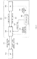
- FIG. 2 is a drawing illustrating an operation of a determination device according to another form of the present invention.
- An apparatus for lane change control 100 in one form of the present disclosure may be implemented in a vehicle.
- the apparatus 100 may be integrated with control units in the vehicle.
- the apparatus 100 may be implemented independently of the control units in the vehicle and may be connected with the control units of the vehicle by a separate connection means.
- the apparatus 100 may be driven as a lane change assist system.
- the lane change assist system may refer to a system which assists in controlling steering torque and vehicle speed and safely changing a lane without a collision with another vehicle located on a lane to be changed, when a driver wants to change the lane while driving.
- the apparatus 100 may include a controller 110, an interface 120, a communication device 130, a storage 140, an information collecting device 150, a determination device 160, and a guide device 170.
- the controller 110, the information collecting device 150, the determination device 160, and the guide device 170 of the apparatus 100 maybe implemented as at least one or more processors.
- the controller 110 may process a signal transmitted between respective components of the apparatus 100.
- the interface 120 include an input means for receiving a command from the driver and an output means for outputting an operation state, an operation result, and the like of the apparatus 100.
- the input means may include a key button and may further include a mouse, a joystick, a jog shuttle, a stylus pen, and the like. Furthermore, the input means may include a soft key implemented on a display.
- the output means may include the display and may further include a voice output means such as a speaker.
- a touch sensor such as a touch film, a touch sheet, or a touch pad
- the display may operate as a touch screen and may be implemented in the form of integrating the input means with the output means.
- the display may include at least one of a liquid crystal display (LCD), a thin film transistor-LCD (TFT-LCD), an organic light-emitting diode (OLED), a flexible display, a field emission display (FED), or a three-dimensional (3D) display.
- LCD liquid crystal display
- TFT-LCD thin film transistor-LCD
- OLED organic light-emitting diode
- flexible display a field emission display
- FED field emission display
- 3D three-dimensional
- the communication device 130 may include a communication module for supporting a communication interface with sensors, electronics, and/or control units mounted on the vehicle.
- the communication module may receive driving information of the vehicle from sensors loaded into the vehicle.
- the communication module may receive location information of the vehicle from a navigation device.
- the communication module may include a module for supporting vehicle network communication such as controller area network (CAN) communication, local interconnect network (LIN) communication, and flex-ray communication.
- vehicle network communication such as controller area network (CAN) communication, local interconnect network (LIN) communication, and flex-ray communication.
- the storage 140 may store data, an algorithm, and/or the like desired for operating the apparatus 100.
- the storage 140 may store driving information of the vehicle, received via the communication device 130 and may store condition information for determining an intention for the driver to use a lane change control function. Furthermore, the storage 140 may store a command, and/or an algorithm for configuring an information screen for notifying the driver that the lane change control function is deactivated. Moreover, the storage 140 may store a command and/or an algorithm for lane change control.
- the storage 140 may include storage media such as a random access memory (RAM), a static RAM (SRAM), a read-only memory (ROM), a programmable ROM (PROM), and an electrically erasable PROM (EEPROM).
- RAM random access memory
- SRAM static RAM
- ROM read-only memory
- PROM programmable ROM
- EEPROM electrically erasable PROM
- the information collecting device 150 may collect a plurality of information desired to implement the lane change control function.
- the information collecting device 150 may collect location information of the vehicle, for example, information indicating that the vehicle enters a limit-access road such as a highway, from the navigation device via the communication device 130. Furthermore, the information collecting device 150 may collect driving information, such as a state where a lane change control switch is turned on/off, a state where a turn signal switch is turned on/off, steering torque, a vehicle speed, detection information associated with a surrounding, a time to collision (TTC) with the surrounding vehicle, and a relative distance from the surrounding vehicle.
- driving information such as a state where a lane change control switch is turned on/off, a state where a turn signal switch is turned on/off, steering torque, a vehicle speed, detection information associated with a surrounding, a time to collision (TTC) with the surrounding vehicle, and a relative distance from the surrounding vehicle.
- the determination device 160 may determine whether the vehicle enters a road section capable of performing lane change control (hereinafter referred to as "lane change control section"), from location information of the vehicle, collected by the information collecting device 150. For example, the determination device 160 may determine whether the vehicle enters the lane change control section, based on information indicating that the vehicle enters a limited-access road, received from the navigation device.
- lane change control section a road section capable of performing lane change control
- the determination device 160 may determine whether the lane change control switch is turned on, from information about driving of the vehicle, collected by the information collecting device 150. When it is verified that the lane change control switch is turned off, the determination device 160 may determine whether operation conditions preset to determine an intention for the driver to use the lane change control function are met.
- the determination device 160 may determine a first condition for a state of the turn signal switch is met. In this case, when the turn signal switch is operated to be converted into an on state and when the on state of the turn signal switch is maintained longer than or equal to a reference time, the determination device 160 may determine that the first condition is met.
- the determination device 160 may determine whether the operation of the turn signal switch is a full-turn operation or a half-turn operation. In this case, when the on state of the turn signal switch is maintained longer than or equal to the reference time by the half-turn operation of the turn signal switch, the determination device 160 may determine that the first condition is met.
- the determination device 160 may determine whether a second condition for steering torque is met. In this case, when a state where the steering torque is less than reference torque is maintained longer than or equal to a reference time, the determination device 160 may determine whether the second condition is met.
- the steering torque when the driver directly performs a lane change, the steering torque may be greater than or equal to the reference torque.
- the determination device 160 may determine whether the second condition is met to exclude that the driver directly performs a lane change.
- the determination device 160 may determine whether a third condition for a collision risk with a surrounding vehicle located on a lane to be changed is met. In this case, when a time to collision (TTC) with the surrounding vehicle is longer than or equal to a collision reference time and when a relative distance from the surrounding vehicle is greater than a reference distance, the determination device 160 may determine that the third condition is met.
- TTC time to collision
- the determination device 160 may determine whether the first condition, the second condition, and the third condition are met and may predict and determine an intention for the driver to use the lane change control function based on the determined result.
- the determination device 160 may predict and determine an intention for the driver to use the lane change control function based on the result of determining the first to third conditions as shown in reference numerals 211, 213, and 215 of FIG. 2 and may output the result of determining the intention for the driver to use the lane change control function as shown in reference numeral 221.
- the determination device 160 may determine that there is no intention for the driver to use the lane change control function. In this case, the determination device 160 may output a first signal indicating that the driver does not have the intention to use the lane change control function to the controller 110. Thus, the controller 110 may keep the lane change control function inactive depending on the first signal from the determination device 160.
- the determination device 160 may determine that the driver has the intention to use the lane change control function. In this case, the determination device 160 may output a second signal indicating that the driver has the intention to use the lane change control function to the controller 110 and/or the guide device 170.
- the guide device 170 may configure an information screen for inquiring about approval to use the lane change control function depending on the second signal from the determination device 160 and may output the configured information screen on a display of the interface 120.
- the information screen may be output in the form of pop-up. An exemplary form for the information screen will be described with reference to FIG. 4 .
- the controller 110 may determine to activate or deactivate the lane change control function depending on feedback of the driver on the information screen.
- the controller 110 may activate the lane change control function.
- the controller 110 may output a control signal for controlling steering torque and a vehicle speed to each drive unit of the vehicle to perform lane change control.
- the controller 110 may end the information screen. In this case, the controller 110 may keep the lane change function inactive.
- the apparatus 100 may determine an intention of the driver when the vehicle enters a lane change control section and may notify the driver that the lane change control function is inactivated, such that the driver may recognize that the lane change control function is deactivated.
- the determination device 160 may determine whether the vehicle enters (departs from) the lane change control section. In this case, when it is verified that the vehicle enters (departs from) the lane change control section, the determination device 160 may output the result to the controller 110.
- the controller 110 may end the lane change control and may convert the lane change control function into an inactive state.
- the apparatus 100 may be implemented in the form of an independent hardware device including a memory and a processor for processing each operation or may be driven in the form of being included in another hardware device such as a microprocessor or a universal computer system.
- FIG. 3 is a drawing illustrating a state transition of a lane change control system according to another form of the present disclosure.
- reference numeral 310 may indicate a state of a lane change control function when a vehicle enters (departs from) a lane change control section.
- Reference numeral 320 may indicate state transition flow of the lane change control function when the vehicle enters the lane change control section.
- the lane change control function may become an off state when the vehicle enters (departs from) the lane change control section.
- the lane change control function when the lane change control function is in the off state before the vehicle enters (departs from) the lane change control section, it may be kept off after the vehicle enters (departs from) the section. Meanwhile, when the lane change control function is in the on state before the vehicle enters (departs from) the lane change control section, it may automatically change to the off state after the vehicle enters (departs from) the section.
- the lane change control function may fail to automatically change to an on state when the vehicle enters the lane change control section.
- the lane change control function may change from an off state 330 to an on state 350.
- the lane change control switch is turned off as shown in reference numeral 351
- the lane change control function may change from the on state 350 to the off state 330.
- the lane change control function may change from the off state 330 to the on state 350 depending on driver feedback input through pop-up which is output on a display of an apparatus 100 of FIG. 1 based on the determination of an intention for the driver to use the lane change control function.
- the lane change control function may be maintained in the off state 330.
- FIG. 4 is a drawing illustrating an operation of a guide device in another form of the present invention.
- reference numeral 411 may indicate an information screen configured by a guide device 170 of FIG. 1 .
- the information screen 411 may include an information message 413, "Do you want to use the lane change control function?", for inquiring about approval to use the lane change control function and an OK button 415 for driver feedback.
- a driver may verify the information message 413 on the information screen 411 displayed on a display of an interface 120 of FIG. 1 and may operate the OK button 415.
- an apparatus 100 of FIG. 1 may activate the lane change control function as the driver operates the OK button 415 on the information screen 411 and may perform lane change control.
- FIG. 5 is a flowchart illustrating an operation of a method for lane change control in one form of the present invention.
- an apparatus 100 of FIG. 1 may determine whether a lane change control switch is turned on.
- the apparatus 100 may set a lane change control function to an on state.
- the apparatus 100 may perform lane change control.
- the apparatus 100 may determine whether all of predetermined operation conditions are met, through operations S130 to S170. When all the operation conditions are met, in operation S180, the apparatus 100 may verify an intention for a driver to use the lane change control function.
- the apparatus 100 may determine whether a turn signal switch is operated in operation S130, whether steering torque is less than reference torque T Drv.LC in operation S140, and whether the states of operations S130 and S140 are kept longer than or equal to a reference time ⁇ t 1 in operation S150.
- the apparatus 100 may determine whether a time to collision (TTC) with a surrounding vehicle on a lane to be changed is longer than a collision reference time t c in operation S160 and whether a relative distance from the surrounding vehicle is greater than a reference distance D Mgn.LC in operation S170.
- TTC time to collision
- the apparatus 100 may guide the driver to convert the lane change control function into an on state.
- the apparatus 100 may display an information screen for inquiring about approval to use the lane change control function on its display.
- the apparatus 100 may set the lane change control function to the on state.
- the apparatus 100 may perform lane change control.
- the apparatus 100 may end an information screen. Thereafter, the apparatus 100 may perform the operation again from operation S110.
- FIG. 6 is a block diagram illustrating a configuration of a computing system which executes a method according to an exemplary form of the present invention.
- a computing system 1000 may include at least one processor 1100, a memory 1300, a user interface input device 1400, a user interface output device 1500, a storage 1600, and a network interface 1700, which are connected with each other via a bus 1200.
- the processor 1100 may be a central processing unit (CPU) or a semiconductor device for processing instructions stored in the memory 1300 and/or the storage 1600.
- CPU central processing unit
- Each of the memory 1300 and the storage 1600 may include various types of volatile or non-volatile storage media.
- the memory 1300 may include a read only memory (ROM) and a random access memory (RAM).
- the operations of the methods or algorithms described in connection with the forms disclosed in the specification may be directly implemented with a hardware module, a software module, or combinations thereof, executed by the processor 1100.
- the software module may reside on a storage medium (e.g., the memory 1300 and/or the storage 1600) such as a RAM, a flash memory, a ROM, an erasable and programmable ROM (EPROM), an electrically EPROM (EEPROM), a register, a hard disc, a removable disc, or a compact disc-ROM (CD-ROM).
- An exemplary storage medium may be coupled to the processor 1100.
- the processor 1100 may read out information from the storage medium and may write information in the storage medium.
- the storage medium may be integrated with the processor 1100.
- the processor and storage medium may reside in an application specific integrated circuit (ASIC).
- the ASIC may reside in a user terminal.
- the processor and storage medium may reside as a separate component of the user terminal.
- the apparatus may determine whether a set driving condition is met when the vehicle enters a road section capable of performing lane change control to determine an intention for a driver to use a lane change control function and may notify the driver that the lane change control function is deactivated, such that the driver may quickly recognize that the lane change control function is deactivated.
Landscapes
- Engineering & Computer Science (AREA)
- Automation & Control Theory (AREA)
- Transportation (AREA)
- Mechanical Engineering (AREA)
- Human Computer Interaction (AREA)
- Chemical & Material Sciences (AREA)
- Combustion & Propulsion (AREA)
- Physics & Mathematics (AREA)
- General Physics & Mathematics (AREA)
- Traffic Control Systems (AREA)
- Control Of Driving Devices And Active Controlling Of Vehicle (AREA)
Claims (11)
- Einrichtung (100) zur Spurwechselsteuerung, umfassend:eine Bestimmungsvorrichtung (160), welche konfiguriert ist, um aus Ortungsinformationen des Fahrzeugs zu bestimmen, ob ein Fahrzeug in einen Straßenabschnitt einfährt, welcher in der Lage ist, Spurwechselsteuerung durchzuführen und als Spurwechselsteuerungsabschnitt bezeichnet wird, und zu bestimmen, ob eine Vielzahl von vorbestimmten Betriebsbedingungen erfüllt sind, wenn das Fahrzeug in den Spurwechselsteuerungsabschnitt einfährt, und konfiguriert ist, um eine Absicht, eine Spurwechselsteuerungsfunktion zu nutzen, für einen Fahrer des Fahrzeugs zu bestimmen;eine Führungsvorrichtung (170), welche konfiguriert ist, um einen Informationsbildschirm für die Spurwechselsteuerungsfunktion auf Basis der bestimmten Absicht des Fahrers zu konfigurieren; undeine Benutzeroberfläche (120), welche konfiguriert ist, um den konfigurierten Informationsbildschirm anzuzeigen,wobei die Bestimmungsvorrichtung (160) konfiguriert ist, um:zu bestimmen, ob ein Spurwechselsteuerungsschalter eingeschaltet ist, wenn das Fahrzeug in den Spurwechselsteuerungsabschnitt einfährt, unddadurch gekennzeichnet, dass die Bestimmungsvorrichtung (160) weiter konfiguriert ist, umzu bestimmen, ob die Vielzahl von vorbestimmten Betriebsbedingungen erfüllt sind, wenn der Spurwechselsteuerungsschalter ausgeschaltet ist.
- Einrichtung (100) nach Anspruch 1, wobei die Vielzahl von Betriebsbedingungen umfasst: eine erste Bedingung für einen Betrieb eines Blinkerschalters, eine zweite Bedingung für ein Lenkdrehmoment, und eine dritte Bedingung für ein Kollisionsrisiko mit einem umgebenden Fahrzeug, welches sich in einer Zielspur befindet, auf welche sich das Fahrzeug anlässlich des Spurwechsels bewegt.
- Einrichtung (100) nach Anspruch 2, wobei die Bestimmungsvorrichtung (160) konfiguriert ist, um:
zu bestimmen, dass die erste Bedingung erfüllt ist, wenn der Blinkerschalter bedient wird und länger als eine oder gleich einer Referenzzeit aufrechterhalten wird. - Einrichtung (100) nach Anspruch 2, wobei die Bestimmungsvorrichtung (160) konfiguriert ist, um:
zu bestimmen, dass die zweite Bedingung erfüllt ist, wenn ein Zustand, in dem das Lenkdrehmoment kleiner als Referenzdrehmoment ist, länger als eine oder gleich einer Referenzzeit aufrechterhalten wird. - Einrichtung (100) nach Anspruch 2, wobei die Bestimmungsvorrichtung (160) konfiguriert ist, um:
zu bestimmen, dass die dritte Bedingung erfüllt ist, wenn eine Zeit bis zu einer Kollision mit dem umgebenden Fahrzeug länger als eine oder gleich einer Kollisionsreferenzzeit ist, und wenn eine relative Distanz von dem umgebenden Fahrzeug zu dem Fahrzeug größer als eine Referenzdistanz ist. - Einrichtung (100) nach Anspruch 2, wobei die Bestimmungsvorrichtung (160) konfiguriert ist, um:
zu bestimmen, dass der Fahrer die Spurwechselsteuerungsfunktion nutzt, wenn alle der ersten bis dritten Bedingung erfüllt sind. - Einrichtung (100) nach Anspruch 1, wobei der Informationsbildschirm eine Informationsmeldung bezüglich einer Anfrage auf Genehmigung der Nutzung der Spurwechselsteuerungsfunktion umfasst.
- Einrichtung (100) nach Anspruch 7, weiter umfassend:
eine Steuereinheit (110), welche konfiguriert ist, um die Spurwechselsteuerungsfunktion zu aktivieren und die Spurwechselsteuerung für das Fahrzeug durchzuführen, wenn über den Informationsbildschirm eine Rückmeldung von dem Fahrer empfangen wird. - Einrichtung (100) nach Anspruch 8, wobei die Steuereinheit (110) konfiguriert ist, um:
den Informationsbildschirm zu beenden, wenn die Rückmeldung von dem Fahrer nicht innerhalb einer vorbestimmten Zeit über den Informationsbildschirm empfangen wird. - Verfahren zur Spurwechselsteuerung, wobei das Verfahren umfasst:Bestimmen, durch eine Bestimmungsvorrichtung, ob ein Fahrzeug in einen Straßenabschnitt einfährt, welcher in der Lage ist, Spurwechselsteuerung durchzuführen und als Spurwechselsteuerungsabschnitt bezeichnet wird, aus Ortungsinformationen des Fahrzeugs;Bestimmen, durch eine Bestimmungsvorrichtung, ob eine Vielzahl von vorbestimmten Betriebsbedingungen erfüllt sind, wenn das Fahrzeug in den Spurwechselsteuerungsabschnitt einfährt, und Bestimmen einer Absicht für einen Fahrer des Fahrzeugs, eine Spurwechselsteuerungsfunktion zu nutzen;Konfigurieren, durch eine Führungsvorrichtung, eines Informationsbildschirms für die Spurwechselsteuerungsfunktion auf Basis der bestimmten Absicht des Fahrers; undAnzeigen des konfigurierten Informationsbildschirms auf einer Anzeige,wobei Bestimmen der Absicht des Fahrers umfasst:Bestimmen, ob ein Spurwechselsteuerungsschalter eingeschaltet ist, wenn das Fahrzeug in den Spurwechselsteuerungsabschnitt einfährt, undBestimmen, ob die Vielzahl von vorbestimmten Betriebsbedingungen, welche eine erste Bedingung, eine zweite Bedingung und eine dritte Bedingung beinhalten, erfüllt sind, wenn der Spurwechselsteuerungsschalter ausgeschaltet ist.
- Verfahren nach Anspruch 10, wobei Bestimmen, ob die Vielzahl von Betriebsbedingungen erfüllt sind, umfasst:Bestimmen, dass die erste Bedingung erfüllt ist, wenn ein Blinkerschalter länger als eine oder gleich einer Referenzzeit aufrechterhalten und bedient wird,Bestimmen, dass die zweite Bedingung erfüllt ist, wenn ein Zustand, in dem Lenkdrehmoment kleiner als Referenzdrehmoment ist, länger als eine oder gleich einer Referenzzeit aufrechterhalten wird,Bestimmen, dass die dritte Bedingung erfüllt ist, wenn eine Zeit bis zu einer Kollision (TTC) mit dem umgebenden Fahrzeug länger als eine oder gleich einer Kollisionsreferenzzeit ist, und wenn eine relative Distanz von dem umgebenden Fahrzeug zu dem Fahrzeug größer als eine Referenzdistanz ist.
Applications Claiming Priority (1)
| Application Number | Priority Date | Filing Date | Title |
|---|---|---|---|
| KR1020180114940A KR102474816B1 (ko) | 2018-09-27 | 2018-09-27 | 차로 변경 제어 장치 및 방법 |
Publications (2)
| Publication Number | Publication Date |
|---|---|
| EP3628560A1 EP3628560A1 (de) | 2020-04-01 |
| EP3628560B1 true EP3628560B1 (de) | 2021-06-16 |
Family
ID=64664044
Family Applications (1)
| Application Number | Title | Priority Date | Filing Date |
|---|---|---|---|
| EP18210399.4A Active EP3628560B1 (de) | 2018-09-27 | 2018-12-05 | Vorrichtung und verfahren zur spurwechselsteuerung |
Country Status (4)
| Country | Link |
|---|---|
| US (1) | US20200102010A1 (de) |
| EP (1) | EP3628560B1 (de) |
| KR (1) | KR102474816B1 (de) |
| CN (1) | CN110949408B (de) |
Families Citing this family (5)
| Publication number | Priority date | Publication date | Assignee | Title |
|---|---|---|---|---|
| KR20210152144A (ko) * | 2020-06-08 | 2021-12-15 | 주식회사 만도모빌리티솔루션즈 | 운전자 보조 장치 및 운전자 보조 방법 |
| JP7474136B2 (ja) * | 2020-06-30 | 2024-04-24 | 本田技研工業株式会社 | 制御装置、制御方法、およびプログラム |
| JP7157780B2 (ja) * | 2020-08-27 | 2022-10-20 | 本田技研工業株式会社 | 自動運転車用情報提示装置 |
| CN116312052A (zh) * | 2023-03-21 | 2023-06-23 | 长城汽车股份有限公司 | 车辆变道提示方法、系统、设备及车辆 |
| KR20260012839A (ko) * | 2024-07-19 | 2026-01-27 | 현대자동차주식회사 | 자유 차선 변경을 지원하는 차량 및 방법 |
Family Cites Families (15)
| Publication number | Priority date | Publication date | Assignee | Title |
|---|---|---|---|---|
| KR19990057522A (ko) * | 1997-12-30 | 1999-07-15 | 오상수 | 차량의 자동 차선변경 방법 및 그 장치 |
| DE102007002220A1 (de) * | 2006-01-12 | 2007-07-26 | Continental Teves Ag & Co. Ohg | Verfahren und Vorrichtung zur Kollisionswarnung bei Spurwechseln von Fahrzeugen |
| CN101510355B (zh) * | 2009-03-30 | 2010-06-30 | 东南大学 | 一种交叉口进口道禁止变换车道线长度的确定方法 |
| KR101427454B1 (ko) * | 2011-09-16 | 2014-08-08 | 주식회사 만도 | 차선유지 제어장치 및 그 방법 |
| KR101417522B1 (ko) * | 2012-12-27 | 2014-08-06 | 현대자동차주식회사 | 고속도로 자율주행 시스템 및 방법 |
| GB2512317A (en) * | 2013-03-26 | 2014-10-01 | Jaguar Land Rover Ltd | Vehicle control system and method |
| DE102014222836A1 (de) * | 2014-11-10 | 2016-05-12 | Robert Bosch Gmbh | Verfahren zum Betreiben eines Fahrerassistenzsystems und Fahrerassistenzsystem |
| JP6137212B2 (ja) * | 2015-02-02 | 2017-05-31 | トヨタ自動車株式会社 | 運転支援装置 |
| JP6447481B2 (ja) * | 2015-04-03 | 2019-01-09 | 株式会社デンソー | 起動提案装置及び起動提案方法 |
| JP6558732B2 (ja) * | 2015-04-21 | 2019-08-14 | パナソニックIpマネジメント株式会社 | 運転支援方法およびそれを利用した運転支援装置、運転制御装置、車両、運転支援プログラム |
| JP6327719B2 (ja) * | 2016-02-04 | 2018-05-23 | 株式会社Subaru | 車両の走行制御装置 |
| JP6517161B2 (ja) * | 2016-02-18 | 2019-05-22 | 本田技研工業株式会社 | 走行制御装置 |
| DE102016205152A1 (de) * | 2016-03-29 | 2017-10-05 | Avl List Gmbh | Fahrerassistenzsystem zum Unterstützen eines Fahrers beim Führen eines Fahrzeugs |
| CN107161146B (zh) * | 2017-04-05 | 2019-09-24 | 吉利汽车研究院(宁波)有限公司 | 一种高速公路辅助系统 |
| CN108334258A (zh) * | 2018-04-11 | 2018-07-27 | 刘连波 | 自动驾驶辅助装置、自动驾驶辅助方法以及自动驾驶辅助系统 |
-
2018
- 2018-09-27 KR KR1020180114940A patent/KR102474816B1/ko active Active
- 2018-11-28 US US16/202,683 patent/US20200102010A1/en not_active Abandoned
- 2018-12-05 EP EP18210399.4A patent/EP3628560B1/de active Active
- 2018-12-10 CN CN201811503489.9A patent/CN110949408B/zh active Active
Non-Patent Citations (1)
| Title |
|---|
| None * |
Also Published As
| Publication number | Publication date |
|---|---|
| KR20200039034A (ko) | 2020-04-16 |
| US20200102010A1 (en) | 2020-04-02 |
| CN110949408B (zh) | 2024-11-05 |
| CN110949408A (zh) | 2020-04-03 |
| EP3628560A1 (de) | 2020-04-01 |
| KR102474816B1 (ko) | 2022-12-06 |
Similar Documents
| Publication | Publication Date | Title |
|---|---|---|
| EP3628560B1 (de) | Vorrichtung und verfahren zur spurwechselsteuerung | |
| US10836394B2 (en) | Apparatus and method for lane change control | |
| US10535269B2 (en) | Apparatus and method for collision control of vehicle based on boundary | |
| EP3552913B1 (de) | Vorrichtung und verfahren zur steuerung für die ermöglichung eines autonomen systems in einem fahrzeug | |
| CN107415941B (zh) | 驾驶员辅助系统 | |
| US20180364709A1 (en) | Autonomous driving control apparatus for vehicle, autonomous driving control method for vehicle, and vehicle system | |
| EP3240711B1 (de) | Anzeige autonomer manöver für autonome fahrzeuge | |
| EP3552911B1 (de) | Vorrichtung und verfahren zur bereitstellung einer sicherheitsstrategie in einem fahrzeug | |
| KR20190118944A (ko) | 차로 변경 제어 장치 및 방법 | |
| JP2019212297A5 (de) | ||
| EP3552901A2 (de) | Vorrichtung und verfahren zur bereitstellung einer sicherheitsstrategie in einem fahrzeug | |
| CN105818812A (zh) | 用于车辆的高级驾驶员辅助系统 | |
| EP3964416B1 (de) | Vorrichtung zur steuerung des autonomen fahrens eines fahrzeugs und verfahren dazu | |
| US12304560B2 (en) | Method for operating a motor vehicle | |
| EP3552915B1 (de) | Vorrichtung und verfahren zur bereitstellung einer sicherheitsstrategie in einem fahrzeug | |
| CN108382393B (zh) | 驾驶辅助设备和驾驶辅助系统 | |
| US20230264720A1 (en) | Autonomous Vehicle and Control Method Thereof | |
| US12145629B2 (en) | Apparatus for controlling autonomous driving of a vehicle, system having the same and method thereof | |
| US12172646B2 (en) | Control system for a vehicle | |
| KR20210055155A (ko) | 차로 변경 보조 장치, 그를 포함한 시스템 및 그 방법 | |
| KR20240026527A (ko) | 자율주행 차량 제어 장치 및 방법 | |
| CN119116987A (zh) | 用于运行车辆中的安全功能的方法和装置 |
Legal Events
| Date | Code | Title | Description |
|---|---|---|---|
| PUAI | Public reference made under article 153(3) epc to a published international application that has entered the european phase |
Free format text: ORIGINAL CODE: 0009012 |
|
| STAA | Information on the status of an ep patent application or granted ep patent |
Free format text: STATUS: THE APPLICATION HAS BEEN PUBLISHED |
|
| AK | Designated contracting states |
Kind code of ref document: A1 Designated state(s): AL AT BE BG CH CY CZ DE DK EE ES FI FR GB GR HR HU IE IS IT LI LT LU LV MC MK MT NL NO PL PT RO RS SE SI SK SM TR |
|
| AX | Request for extension of the european patent |
Extension state: BA ME |
|
| STAA | Information on the status of an ep patent application or granted ep patent |
Free format text: STATUS: REQUEST FOR EXAMINATION WAS MADE |
|
| 17P | Request for examination filed |
Effective date: 20200909 |
|
| RBV | Designated contracting states (corrected) |
Designated state(s): AL AT BE BG CH CY CZ DE DK EE ES FI FR GB GR HR HU IE IS IT LI LT LU LV MC MK MT NL NO PL PT RO RS SE SI SK SM TR |
|
| GRAP | Despatch of communication of intention to grant a patent |
Free format text: ORIGINAL CODE: EPIDOSNIGR1 |
|
| STAA | Information on the status of an ep patent application or granted ep patent |
Free format text: STATUS: GRANT OF PATENT IS INTENDED |
|
| RIC1 | Information provided on ipc code assigned before grant |
Ipc: B60W 50/08 20200101AFI20200930BHEP Ipc: B60W 50/10 20120101ALI20200930BHEP Ipc: G08G 1/0962 20060101ALI20200930BHEP Ipc: B60W 30/18 20120101ALI20200930BHEP Ipc: G08G 1/16 20060101ALI20200930BHEP Ipc: B60W 50/00 20060101ALN20200930BHEP Ipc: B60W 50/14 20200101ALI20200930BHEP |
|
| RIC1 | Information provided on ipc code assigned before grant |
Ipc: B60W 30/18 20120101ALI20201006BHEP Ipc: G08G 1/0962 20060101ALI20201006BHEP Ipc: B60W 50/00 20060101ALN20201006BHEP Ipc: B60W 50/08 20200101AFI20201006BHEP Ipc: B60W 50/10 20120101ALI20201006BHEP Ipc: G08G 1/16 20060101ALI20201006BHEP Ipc: B60W 50/14 20200101ALI20201006BHEP |
|
| INTG | Intention to grant announced |
Effective date: 20201103 |
|
| GRAJ | Information related to disapproval of communication of intention to grant by the applicant or resumption of examination proceedings by the epo deleted |
Free format text: ORIGINAL CODE: EPIDOSDIGR1 |
|
| STAA | Information on the status of an ep patent application or granted ep patent |
Free format text: STATUS: REQUEST FOR EXAMINATION WAS MADE |
|
| INTC | Intention to grant announced (deleted) | ||
| RIC1 | Information provided on ipc code assigned before grant |
Ipc: B60W 30/18 20120101ALI20210304BHEP Ipc: G08G 1/16 20060101ALI20210304BHEP Ipc: B60W 50/10 20120101ALI20210304BHEP Ipc: B60W 50/08 20200101AFI20210304BHEP Ipc: B60W 50/00 20060101ALN20210304BHEP Ipc: G08G 1/0962 20060101ALI20210304BHEP Ipc: B60W 50/14 20200101ALI20210304BHEP |
|
| GRAP | Despatch of communication of intention to grant a patent |
Free format text: ORIGINAL CODE: EPIDOSNIGR1 |
|
| STAA | Information on the status of an ep patent application or granted ep patent |
Free format text: STATUS: GRANT OF PATENT IS INTENDED |
|
| GRAS | Grant fee paid |
Free format text: ORIGINAL CODE: EPIDOSNIGR3 |
|
| INTG | Intention to grant announced |
Effective date: 20210414 |
|
| GRAA | (expected) grant |
Free format text: ORIGINAL CODE: 0009210 |
|
| STAA | Information on the status of an ep patent application or granted ep patent |
Free format text: STATUS: THE PATENT HAS BEEN GRANTED |
|
| AK | Designated contracting states |
Kind code of ref document: B1 Designated state(s): AL AT BE BG CH CY CZ DE DK EE ES FI FR GB GR HR HU IE IS IT LI LT LU LV MC MK MT NL NO PL PT RO RS SE SI SK SM TR |
|
| REG | Reference to a national code |
Ref country code: GB Ref legal event code: FG4D |
|
| REG | Reference to a national code |
Ref country code: CH Ref legal event code: EP |
|
| REG | Reference to a national code |
Ref country code: DE Ref legal event code: R096 Ref document number: 602018018619 Country of ref document: DE |
|
| REG | Reference to a national code |
Ref country code: AT Ref legal event code: REF Ref document number: 1402104 Country of ref document: AT Kind code of ref document: T Effective date: 20210715 |
|
| REG | Reference to a national code |
Ref country code: IE Ref legal event code: FG4D |
|
| RAP4 | Party data changed (patent owner data changed or rights of a patent transferred) |
Owner name: HYUNDAI MOTOR COMPANY Owner name: KIA CORPORATION |
|
| REG | Reference to a national code |
Ref country code: LT Ref legal event code: MG9D |
|
| PG25 | Lapsed in a contracting state [announced via postgrant information from national office to epo] |
Ref country code: FI Free format text: LAPSE BECAUSE OF FAILURE TO SUBMIT A TRANSLATION OF THE DESCRIPTION OR TO PAY THE FEE WITHIN THE PRESCRIBED TIME-LIMIT Effective date: 20210616 Ref country code: LT Free format text: LAPSE BECAUSE OF FAILURE TO SUBMIT A TRANSLATION OF THE DESCRIPTION OR TO PAY THE FEE WITHIN THE PRESCRIBED TIME-LIMIT Effective date: 20210616 Ref country code: HR Free format text: LAPSE BECAUSE OF FAILURE TO SUBMIT A TRANSLATION OF THE DESCRIPTION OR TO PAY THE FEE WITHIN THE PRESCRIBED TIME-LIMIT Effective date: 20210616 Ref country code: BG Free format text: LAPSE BECAUSE OF FAILURE TO SUBMIT A TRANSLATION OF THE DESCRIPTION OR TO PAY THE FEE WITHIN THE PRESCRIBED TIME-LIMIT Effective date: 20210916 |
|
| REG | Reference to a national code |
Ref country code: AT Ref legal event code: MK05 Ref document number: 1402104 Country of ref document: AT Kind code of ref document: T Effective date: 20210616 |
|
| REG | Reference to a national code |
Ref country code: NL Ref legal event code: MP Effective date: 20210616 |
|
| PG25 | Lapsed in a contracting state [announced via postgrant information from national office to epo] |
Ref country code: GR Free format text: LAPSE BECAUSE OF FAILURE TO SUBMIT A TRANSLATION OF THE DESCRIPTION OR TO PAY THE FEE WITHIN THE PRESCRIBED TIME-LIMIT Effective date: 20210917 Ref country code: LV Free format text: LAPSE BECAUSE OF FAILURE TO SUBMIT A TRANSLATION OF THE DESCRIPTION OR TO PAY THE FEE WITHIN THE PRESCRIBED TIME-LIMIT Effective date: 20210616 Ref country code: NO Free format text: LAPSE BECAUSE OF FAILURE TO SUBMIT A TRANSLATION OF THE DESCRIPTION OR TO PAY THE FEE WITHIN THE PRESCRIBED TIME-LIMIT Effective date: 20210916 Ref country code: RS Free format text: LAPSE BECAUSE OF FAILURE TO SUBMIT A TRANSLATION OF THE DESCRIPTION OR TO PAY THE FEE WITHIN THE PRESCRIBED TIME-LIMIT Effective date: 20210616 Ref country code: SE Free format text: LAPSE BECAUSE OF FAILURE TO SUBMIT A TRANSLATION OF THE DESCRIPTION OR TO PAY THE FEE WITHIN THE PRESCRIBED TIME-LIMIT Effective date: 20210616 |
|
| PG25 | Lapsed in a contracting state [announced via postgrant information from national office to epo] |
Ref country code: RO Free format text: LAPSE BECAUSE OF FAILURE TO SUBMIT A TRANSLATION OF THE DESCRIPTION OR TO PAY THE FEE WITHIN THE PRESCRIBED TIME-LIMIT Effective date: 20210616 Ref country code: PT Free format text: LAPSE BECAUSE OF FAILURE TO SUBMIT A TRANSLATION OF THE DESCRIPTION OR TO PAY THE FEE WITHIN THE PRESCRIBED TIME-LIMIT Effective date: 20211018 Ref country code: NL Free format text: LAPSE BECAUSE OF FAILURE TO SUBMIT A TRANSLATION OF THE DESCRIPTION OR TO PAY THE FEE WITHIN THE PRESCRIBED TIME-LIMIT Effective date: 20210616 Ref country code: CZ Free format text: LAPSE BECAUSE OF FAILURE TO SUBMIT A TRANSLATION OF THE DESCRIPTION OR TO PAY THE FEE WITHIN THE PRESCRIBED TIME-LIMIT Effective date: 20210616 Ref country code: AT Free format text: LAPSE BECAUSE OF FAILURE TO SUBMIT A TRANSLATION OF THE DESCRIPTION OR TO PAY THE FEE WITHIN THE PRESCRIBED TIME-LIMIT Effective date: 20210616 Ref country code: EE Free format text: LAPSE BECAUSE OF FAILURE TO SUBMIT A TRANSLATION OF THE DESCRIPTION OR TO PAY THE FEE WITHIN THE PRESCRIBED TIME-LIMIT Effective date: 20210616 Ref country code: ES Free format text: LAPSE BECAUSE OF FAILURE TO SUBMIT A TRANSLATION OF THE DESCRIPTION OR TO PAY THE FEE WITHIN THE PRESCRIBED TIME-LIMIT Effective date: 20210616 Ref country code: SM Free format text: LAPSE BECAUSE OF FAILURE TO SUBMIT A TRANSLATION OF THE DESCRIPTION OR TO PAY THE FEE WITHIN THE PRESCRIBED TIME-LIMIT Effective date: 20210616 Ref country code: SK Free format text: LAPSE BECAUSE OF FAILURE TO SUBMIT A TRANSLATION OF THE DESCRIPTION OR TO PAY THE FEE WITHIN THE PRESCRIBED TIME-LIMIT Effective date: 20210616 |
|
| PG25 | Lapsed in a contracting state [announced via postgrant information from national office to epo] |
Ref country code: PL Free format text: LAPSE BECAUSE OF FAILURE TO SUBMIT A TRANSLATION OF THE DESCRIPTION OR TO PAY THE FEE WITHIN THE PRESCRIBED TIME-LIMIT Effective date: 20210616 |
|
| REG | Reference to a national code |
Ref country code: DE Ref legal event code: R097 Ref document number: 602018018619 Country of ref document: DE |
|
| PLBE | No opposition filed within time limit |
Free format text: ORIGINAL CODE: 0009261 |
|
| STAA | Information on the status of an ep patent application or granted ep patent |
Free format text: STATUS: NO OPPOSITION FILED WITHIN TIME LIMIT |
|
| PG25 | Lapsed in a contracting state [announced via postgrant information from national office to epo] |
Ref country code: DK Free format text: LAPSE BECAUSE OF FAILURE TO SUBMIT A TRANSLATION OF THE DESCRIPTION OR TO PAY THE FEE WITHIN THE PRESCRIBED TIME-LIMIT Effective date: 20210616 |
|
| 26N | No opposition filed |
Effective date: 20220317 |
|
| PG25 | Lapsed in a contracting state [announced via postgrant information from national office to epo] |
Ref country code: AL Free format text: LAPSE BECAUSE OF FAILURE TO SUBMIT A TRANSLATION OF THE DESCRIPTION OR TO PAY THE FEE WITHIN THE PRESCRIBED TIME-LIMIT Effective date: 20210616 |
|
| PG25 | Lapsed in a contracting state [announced via postgrant information from national office to epo] |
Ref country code: MC Free format text: LAPSE BECAUSE OF FAILURE TO SUBMIT A TRANSLATION OF THE DESCRIPTION OR TO PAY THE FEE WITHIN THE PRESCRIBED TIME-LIMIT Effective date: 20210616 Ref country code: IT Free format text: LAPSE BECAUSE OF FAILURE TO SUBMIT A TRANSLATION OF THE DESCRIPTION OR TO PAY THE FEE WITHIN THE PRESCRIBED TIME-LIMIT Effective date: 20210616 |
|
| REG | Reference to a national code |
Ref country code: CH Ref legal event code: PL |
|
| REG | Reference to a national code |
Ref country code: BE Ref legal event code: MM Effective date: 20211231 |
|
| PG25 | Lapsed in a contracting state [announced via postgrant information from national office to epo] |
Ref country code: LU Free format text: LAPSE BECAUSE OF NON-PAYMENT OF DUE FEES Effective date: 20211205 Ref country code: IE Free format text: LAPSE BECAUSE OF NON-PAYMENT OF DUE FEES Effective date: 20211205 |
|
| PG25 | Lapsed in a contracting state [announced via postgrant information from national office to epo] |
Ref country code: BE Free format text: LAPSE BECAUSE OF NON-PAYMENT OF DUE FEES Effective date: 20211231 |
|
| PG25 | Lapsed in a contracting state [announced via postgrant information from national office to epo] |
Ref country code: LI Free format text: LAPSE BECAUSE OF NON-PAYMENT OF DUE FEES Effective date: 20211231 Ref country code: CH Free format text: LAPSE BECAUSE OF NON-PAYMENT OF DUE FEES Effective date: 20211231 |
|
| P01 | Opt-out of the competence of the unified patent court (upc) registered |
Effective date: 20230505 |
|
| PG25 | Lapsed in a contracting state [announced via postgrant information from national office to epo] |
Ref country code: CY Free format text: LAPSE BECAUSE OF FAILURE TO SUBMIT A TRANSLATION OF THE DESCRIPTION OR TO PAY THE FEE WITHIN THE PRESCRIBED TIME-LIMIT Effective date: 20210616 |
|
| PG25 | Lapsed in a contracting state [announced via postgrant information from national office to epo] |
Ref country code: HU Free format text: LAPSE BECAUSE OF FAILURE TO SUBMIT A TRANSLATION OF THE DESCRIPTION OR TO PAY THE FEE WITHIN THE PRESCRIBED TIME-LIMIT; INVALID AB INITIO Effective date: 20181205 |
|
| PG25 | Lapsed in a contracting state [announced via postgrant information from national office to epo] |
Ref country code: MK Free format text: LAPSE BECAUSE OF FAILURE TO SUBMIT A TRANSLATION OF THE DESCRIPTION OR TO PAY THE FEE WITHIN THE PRESCRIBED TIME-LIMIT Effective date: 20210616 |
|
| PG25 | Lapsed in a contracting state [announced via postgrant information from national office to epo] |
Ref country code: TR Free format text: LAPSE BECAUSE OF FAILURE TO SUBMIT A TRANSLATION OF THE DESCRIPTION OR TO PAY THE FEE WITHIN THE PRESCRIBED TIME-LIMIT Effective date: 20210616 |
|
| PG25 | Lapsed in a contracting state [announced via postgrant information from national office to epo] |
Ref country code: MT Free format text: LAPSE BECAUSE OF FAILURE TO SUBMIT A TRANSLATION OF THE DESCRIPTION OR TO PAY THE FEE WITHIN THE PRESCRIBED TIME-LIMIT Effective date: 20210616 |
|
| PGFP | Annual fee paid to national office [announced via postgrant information from national office to epo] |
Ref country code: DE Payment date: 20251120 Year of fee payment: 8 |
|
| PGFP | Annual fee paid to national office [announced via postgrant information from national office to epo] |
Ref country code: GB Payment date: 20251120 Year of fee payment: 8 |
|
| PGFP | Annual fee paid to national office [announced via postgrant information from national office to epo] |
Ref country code: FR Payment date: 20251125 Year of fee payment: 8 |