EP3627232B1 - Self-winding watch movement with time display hands located on the rotor side - Google Patents
Self-winding watch movement with time display hands located on the rotor side Download PDFInfo
- Publication number
- EP3627232B1 EP3627232B1 EP18196380.2A EP18196380A EP3627232B1 EP 3627232 B1 EP3627232 B1 EP 3627232B1 EP 18196380 A EP18196380 A EP 18196380A EP 3627232 B1 EP3627232 B1 EP 3627232B1
- Authority
- EP
- European Patent Office
- Prior art keywords
- plate
- barrel
- hour
- wheel
- ring
- Prior art date
- Legal status (The legal status is an assumption and is not a legal conclusion. Google has not performed a legal analysis and makes no representation as to the accuracy of the status listed.)
- Active
Links
- 238000004804 winding Methods 0.000 title claims description 13
- 238000005096 rolling process Methods 0.000 claims description 3
- 230000005540 biological transmission Effects 0.000 claims description 2
- 230000007246 mechanism Effects 0.000 description 11
- BASFCYQUMIYNBI-UHFFFAOYSA-N platinum Chemical compound [Pt] BASFCYQUMIYNBI-UHFFFAOYSA-N 0.000 description 9
- 210000004247 hand Anatomy 0.000 description 7
- 230000008901 benefit Effects 0.000 description 4
- 239000003638 chemical reducing agent Substances 0.000 description 3
- 229910000831 Steel Inorganic materials 0.000 description 2
- 230000009977 dual effect Effects 0.000 description 2
- 239000003623 enhancer Substances 0.000 description 2
- 239000000463 material Substances 0.000 description 2
- 239000007787 solid Substances 0.000 description 2
- 239000010959 steel Substances 0.000 description 2
- 229910001369 Brass Inorganic materials 0.000 description 1
- 235000008612 Gnetum gnemon Nutrition 0.000 description 1
- 240000000018 Gnetum gnemon Species 0.000 description 1
- 239000006096 absorbing agent Substances 0.000 description 1
- 238000004026 adhesive bonding Methods 0.000 description 1
- 239000010951 brass Substances 0.000 description 1
- 238000002788 crimping Methods 0.000 description 1
- 239000002184 metal Substances 0.000 description 1
- 229910052594 sapphire Inorganic materials 0.000 description 1
- 239000010980 sapphire Substances 0.000 description 1
- 239000012780 transparent material Substances 0.000 description 1
- 210000000707 wrist Anatomy 0.000 description 1
Images


Classifications
-
- G—PHYSICS
- G04—HOROLOGY
- G04B—MECHANICALLY-DRIVEN CLOCKS OR WATCHES; MECHANICAL PARTS OF CLOCKS OR WATCHES IN GENERAL; TIME PIECES USING THE POSITION OF THE SUN, MOON OR STARS
- G04B5/00—Automatic winding up
- G04B5/02—Automatic winding up by self-winding caused by the movement of the watch
- G04B5/10—Automatic winding up by self-winding caused by the movement of the watch by oscillating weights the movement of which is not limited
- G04B5/14—Automatic winding up by self-winding caused by the movement of the watch by oscillating weights the movement of which is not limited acting in both directions
-
- G—PHYSICS
- G04—HOROLOGY
- G04B—MECHANICALLY-DRIVEN CLOCKS OR WATCHES; MECHANICAL PARTS OF CLOCKS OR WATCHES IN GENERAL; TIME PIECES USING THE POSITION OF THE SUN, MOON OR STARS
- G04B5/00—Automatic winding up
- G04B5/02—Automatic winding up by self-winding caused by the movement of the watch
-
- G—PHYSICS
- G04—HOROLOGY
- G04B—MECHANICALLY-DRIVEN CLOCKS OR WATCHES; MECHANICAL PARTS OF CLOCKS OR WATCHES IN GENERAL; TIME PIECES USING THE POSITION OF THE SUN, MOON OR STARS
- G04B5/00—Automatic winding up
- G04B5/02—Automatic winding up by self-winding caused by the movement of the watch
- G04B5/18—Supports, suspensions or guide arrangements, for oscillating weights
- G04B5/181—The bearing of the rocking bar is in the centre of rotation combined with a support or guide arrangement
-
- G—PHYSICS
- G04—HOROLOGY
- G04B—MECHANICALLY-DRIVEN CLOCKS OR WATCHES; MECHANICAL PARTS OF CLOCKS OR WATCHES IN GENERAL; TIME PIECES USING THE POSITION OF THE SUN, MOON OR STARS
- G04B13/00—Gearwork
- G04B13/02—Wheels; Pinions; Spindles; Pivots
-
- G—PHYSICS
- G04—HOROLOGY
- G04B—MECHANICALLY-DRIVEN CLOCKS OR WATCHES; MECHANICAL PARTS OF CLOCKS OR WATCHES IN GENERAL; TIME PIECES USING THE POSITION OF THE SUN, MOON OR STARS
- G04B45/00—Time pieces of which the indicating means or cases provoke special effects, e.g. aesthetic effects
- G04B45/02—Time pieces of which the clockwork is visible partly or wholly
-
- G—PHYSICS
- G04—HOROLOGY
- G04B—MECHANICALLY-DRIVEN CLOCKS OR WATCHES; MECHANICAL PARTS OF CLOCKS OR WATCHES IN GENERAL; TIME PIECES USING THE POSITION OF THE SUN, MOON OR STARS
- G04B5/00—Automatic winding up
- G04B5/02—Automatic winding up by self-winding caused by the movement of the watch
- G04B5/16—Construction of the weights
- G04B5/165—Weights consisting of several parts
-
- G—PHYSICS
- G04—HOROLOGY
- G04B—MECHANICALLY-DRIVEN CLOCKS OR WATCHES; MECHANICAL PARTS OF CLOCKS OR WATCHES IN GENERAL; TIME PIECES USING THE POSITION OF THE SUN, MOON OR STARS
- G04B5/00—Automatic winding up
- G04B5/02—Automatic winding up by self-winding caused by the movement of the watch
- G04B5/18—Supports, suspensions or guide arrangements, for oscillating weights
- G04B5/184—Guide arrangement of the moving weight in a circular course
-
- G—PHYSICS
- G04—HOROLOGY
- G04B—MECHANICALLY-DRIVEN CLOCKS OR WATCHES; MECHANICAL PARTS OF CLOCKS OR WATCHES IN GENERAL; TIME PIECES USING THE POSITION OF THE SUN, MOON OR STARS
- G04B5/00—Automatic winding up
- G04B5/02—Automatic winding up by self-winding caused by the movement of the watch
- G04B5/18—Supports, suspensions or guide arrangements, for oscillating weights
- G04B5/19—Suspension of the oscillating weight at its centre of rotation
Definitions
- the invention relates to the field of watchmaking. It relates, more precisely, to an automatic winding horological movement, intended to equip a wristwatch.
- a typical mechanism comprises an oscillating mass in the form of a rotor whose rotation is transmitted to the barrel via a reduction gear.
- a rotor comprises a hub, by which it is fixed (with the possibility of rotation) on the plate of the movement, a rim (or “support”) integral with the hub, as well as a heavy (or “heavy”) annular sector. integral with the rim and which, by the imbalance which it induces in the distribution of the masses of the rotor, drives the latter in rotation during the movements of the watch.
- the hands are located on the side of a front face of the plate and the rotor is on the contrary located on the side of a rear face of the plate, that is to say on the side opposite the hands.
- the watch movement proposed in the patent CH 703 964 provides for the passage of the hour and minute barrels in a central opening made in the hub of the rotor, which is placed between the body of the watch movement (including the plate, the bridges and the mobile mounted pivoting between the plate and the bridges) and the hour and minute hands.
- the document EP 2 551 731 A1 discloses an oscillating mass arranged above the switch; the mass is mounted using an annular frame.
- An objective of the invention is therefore, in a self-winding watch movement with a rotor located on the time display side, to solve the mentioned problems.
- the movement comprises a bearing provided with a ring fixed relative to the plate, a ring movable in rotation relative to the ring fixed around the central axis, and interposed rolling elements. between the rings, the booster shaft being integral with the movable ring.
- the movable ring preferably carries a toothed ring gear in gear relationship with the barrel via a reduction gear.
- the fixed ring is an inner ring (preferably secured to the bridge by a central screw) of the bearing and the movable ring is an outer ring.
- the watch movement advantageously comprises a sleeve fixed relative to the plate and on which are mounted the hours barrel and the minute cannon.
- the hours barrel is nested on the case and the minute barrel is nested on the hour barrel.
- the roadway and the hours mobile are advantageously mounted on an upper bridge fixed to the plate, this upper bridge having an internal face on the side of the plate, and an opposite external face.
- the barrel is preferably mounted on the side of the internal face of the upper deck, while the carriageway, the mobile of the hours and the rotor are mounted on the side of the external face of the upper deck.
- FIG. 1 On the FIG. 1 a self-winding horological movement 1 is shown. This movement 1 is intended to equip a wristwatch, able to be worn on the wrist.
- the movement 1 comprises, first of all, a plate 2, which is in the form of a rigid part (preferably made of metal, for example steel), intended to form a support for various components of the movement, fixed or mobile .
- the plate 2 has a lower face 3 and an upper face 4, opposite to the lower face 3.
- the movement 1 comprises, secondly, a barrel 5 mounted in rotation relative to the plate 3 and provided with a primary toothed wheel 6.
- the barrel comprises a barrel shaft 7 by which the barrel is rotatably mounted on the plate 2, a barrel drum 8, and a barrel spring (not shown) secured, by an internal end, to the barrel shaft 7 and, by an outer end, of the barrel drum 8.
- the barrel is provided with a secondary toothed wheel 9 (also called a "ratchet") and separate from the primary toothed wheel 6.
- a secondary toothed wheel 9 also called a "ratchet”
- the movement 1 comprises, thirdly, a winder 10 which comprises a winding stem 11 carrying, at an outer end, a winding crown 12.
- the winder comprises a winding mechanism 13 by which the winding rod 11 engages, in a winding position, the secondary toothed wheel 9 of the barrel 5 in order to ensure its rotation manually and thus to arm the spring.
- the movement 1 comprises, in the fourth place, a carriageway 14 mounted in rotation with respect to the plate 2 about a central axis A.
- the causeway includes a 15 minute barrel which carries a 16 minute hand.
- the carriageway 14 is in a gear relationship with the primary toothed wheel 6 of the barrel by means of a timer gear 17. More precisely, and according to one embodiment illustrated in particular on the FIG. 7 , the carriageway 14 comprises a minute pinion 18, integral with the minute barrel 15 (or integrally formed therewith), and the timer gear 17 comprises a timer wheel 19.1 meshing with the minute pinion.
- the timer gear 17 is mounted in rotation with respect to the plate 2.
- the movement 1 comprises, in the fifth place, a mobile 20 of the hours, mounted in rotation with respect to the plate 2 around the central axis A.
- the hours mobile comprises a 21 hour cannon which carries a 22 hour hand.
- the hours mobile 20 is in a gear relationship with the roadway 14. More precisely, and according to an embodiment illustrated in FIG. FIG. 7 , the hours mobile comprises an hours pinion 23, integral with the hours barrel 21 (or integrally formed therewith), and the movement 1 comprises a pinion 24 which rotates the hours mobile to the roadway 14 in a gear ratio R of 1/12.
- the gears are chosen so that the gear ratio R is equal to 1/12.
- the carriageway 14, including the 15 minute barrel and the 16 minute hand, is located on the side of the upper face 4 of the plate 2.
- the 20 hour mobile, including the 21 hour barrel and the 22 hour hand, is located on the side of the upper face 4 of plate 2.
- the movement 1 comprises, in the sixth place, an oscillating mass in the form of a rotor 25 mounted in rotation with respect to the plate 2 around the central axis A, on the same side of the plate 2 as the roadway 14 and the mobile. 20 hours - in this case on the side of the upper face 4 of the plate.
- the rim 27 is in the form of a solid disc, but it could be perforated.
- the rim is a solid disc made of a transparent material, e.g. in industrial sapphire.
- the heavy annular sector 28 appears, for example. in the form of a half-ring made of a material whose density is greater than that of the material of the rim 27.
- the heavy annular sector is made of brass.
- the attachment of the heavy annular sector 28 to the rim 27 is e.g. produced by screwing, riveting, crimping or gluing.
- the movement 1 comprises, in the seventh place, a booster shaft 29 integral with the central hub 26 and by which the latter is mounted in rotation with respect to the plate 2.
- the booster shaft 29 is preferably in the form of a hollow cylinder, produced for example. in steel.
- the booster shaft and the central hub could form a single piece. However, in the example illustrated, the booster shaft and the central hub form two separate parts fixed to one another. According to a particular embodiment, the central hub is driven onto an upper end of the booster shaft.
- the 15 minute barrel and the 21 hour barrel are mounted coaxially around the booster shaft 29, the minute hand 16 and the hour hand 22 being located between the plate 2 and the rim 27 of the rotor .
- this arrangement makes it possible to position the hands 16, 22 as close as possible to a possible dial or a crown bearing a time scale, for the benefit of readability of the hours.
- the bearing 30 is advantageously mounted on an intermediate bridge 34 fixed on the plate 2.
- the fixed ring 31 is an inner ring of the bearing 30, and the movable ring 32 is an outer ring.
- the booster shaft 29 is driven out on the movable ring 32 located outside the bearing.
- the movable ring 32 preferably carries a toothed crown 37 in a gear relationship with the barrel 5, via a reduction gear 38 (visible on the FIG. 5 ). More precisely, the reduction gear is in a gear relationship with the secondary toothed wheel 9 (cog) of the barrel 5.
- the guns 15, 21 freely surround the booster shaft 29.
- the respective internal diameters of the barrels 15, 21 are greater than the external diameter of the booster shaft, at least for the part of this booster shaft located inside the two barrels.
- the movement 1 advantageously comprises a sleeve 39 surrounding the enhancer shaft, this sleeve being fixed relative to the plate 2.
- the hours barrel 20 and the minutes barrel 15 are mounted on the sleeve.
- the sleeve is integral (eg by driving) an upper bridge 40 fixed on the plate 2. More precisely, in the example illustrated, the upper bridge is fixed on the intermediate bridge 34.
- the inner ring 31 of the bearing 30 is fixed to the intermediate bridge by the central screw 35, this central screw also securing to this bridge the intermediate part 36, which has a bottom with a central hole for the passage of the central screw and a tube rigid in which the head of this central screw is located, this rigid tube being located inside a central opening presented by the booster shaft, this booster shaft forming a rotating tube.
- the upper deck 40 is clearly visible on the FIG. 2 and FIG. 3 .
- the attachment of the upper deck to the intermediate deck 34 is e.g. carried out by means of screws 41, here three in number.
- the upper bridge is pierced with holes 42 and carries pins 43 for guiding in rotation the moving parts of the movement 2, and in particular components of the timer gear 17.
- a first lanterning is advantageously provided at the interface between the sleeve 39 and the hour barrel 21 to allow the latter to rotate (with the hour hand 22) relative to the sleeve.
- a second lanterning is advantageously provided at the interface between the hour barrel 21 and the minute barrel 15 to allow the latter to rotate (with the minute hand 16) relative to the hour barrel.
- the barrel 5 is mounted on the side of an internal face 44 (turned towards the plate 2) of the upper bridge 40 (and more precisely between the intermediate bridge 34 and the plate 2), while the roadway 14, the mobile 20 of the hours and the rotor 25 are mounted on the side of an outer face 45 (opposite to the plate 2) of the upper bridge.
- the axis 49 crosses not only the upper bridge 40 but also the intermediate bridge 34.
- the movement 1 can also be equipped with a small second hand 50, off-center with respect to the central axis A.
- the small seconds hand is driven out on an axis 51 integral with a seconds wheel 52, in gear relation with the roadway 14 in a 1/60 ratio.
- the movement 1 comprises a bearing 53, provided with a guide ring 54 which surrounds the roadway 14, and a foot 55 by which the bearing 53 is fixed to the upper deck 40.
- the fact that the rotor 25 is located on the same side as the time display i.e. the hands 15, 22
- the time display i.e. the hands 15, 22
- the fact that the rotor 25 surmounts the needles 15, 22 makes it possible to position them as close as possible to the body of the movement and an hour graduation which may be located on the rear face of this body, for the benefit of the readability of the display.
- the watch movement which has just been described can easily also have an additional time display located on the side of the front face of plate 2.
- the second display possibly corresponding for example to a different time zone from that of the first display.
Description
L'invention a trait au domaine de l'horlogerie. Elle concerne, plus précisément, un mouvement horloger à remontage automatique, destiné à équiper une montre bracelet.The invention relates to the field of watchmaking. It relates, more precisely, to an automatic winding horological movement, intended to equip a wristwatch.
Les premiers mécanismes horlogers à remontage automatique documentés datent de la fin du 18e siècle. Ces mécanismes ont connu de nombreux perfectionnements. Un mécanisme typique, aujourd'hui largement répandu, comprend une masse oscillante sous forme d'un rotor dont la rotation est transmise au barillet via un rouage réducteur.The first documented self-winding watch mechanisms date from the end of the 18th century. These mechanisms have undergone many improvements. A typical mechanism, widely used today, comprises an oscillating mass in the form of a rotor whose rotation is transmitted to the barrel via a reduction gear.
Classiquement, un rotor comprend un moyeu, par lequel il est fixé (avec possibilité de rotation) sur la platine du mouvement, une jante (ou « support ») solidaire du moyeu, ainsi qu'un secteur annulaire lourd (ou « pesant ») solidaire de la jante et qui, par le déséquilibre qu'il induit dans la répartition des masses du rotor, entraîne celui-ci en rotation lors des mouvements de la montre.Conventionally, a rotor comprises a hub, by which it is fixed (with the possibility of rotation) on the plate of the movement, a rim (or “support”) integral with the hub, as well as a heavy (or “heavy”) annular sector. integral with the rim and which, by the imbalance which it induces in the distribution of the masses of the rotor, drives the latter in rotation during the movements of the watch.
Dans de nombreuses montres, les aiguilles sont situées du côté d'une face avant de la platine et le rotor est au contraire situé du côté d'une face arrière de la platine, c'est-à-dire du côté opposé aux aiguilles.In many watches, the hands are located on the side of a front face of the plate and the rotor is on the contrary located on the side of a rear face of the plate, that is to say on the side opposite the hands.
Cependant il existe des réalisations dans lesquelles le rotor est situé du même côté que les aiguilles, cf. par ex. le brevet suisse
Le mouvement horloger proposé dans le brevet
Il en résulte que les aiguilles des heures et des minutes sont situées à une assez grande distance du corps du mouvement, et en particulier d'une éventuelle graduation de lecture des heures.The result is that the hour and minute hands are located at a fairly large distance from the body of the movement, and in particular from any graduation for reading the hours.
Cette disposition est problématique car, d'une part, elle nuit à une lecture précise de l'heure. D'autre part, son esthétique est contestable en raison de l'espace important séparant les aiguilles et le corps du mouvement (en tenant compte du fait que cet espace est au moins en partie comblé par le rotor).This arrangement is problematic because, on the one hand, it interferes with accurate reading of the time. On the other hand, its aesthetics are questionable because of the large space separating the hands and the body of the movement (taking into account that this space is at least partly filled by the rotor).
Le document
Un objectif de l'invention est par conséquent, dans un mouvement horloger à remontage automatique et à rotor situé du côté de l'affichage de l'heure, de résoudre les problèmes mentionnés.An objective of the invention is therefore, in a self-winding watch movement with a rotor located on the time display side, to solve the mentioned problems.
Pour atteindre l'objectif précité, il est proposé un mouvement horloger à remontage automatique, qui comprend :
- Une platine ;
- Un barillet monté en rotation par rapport à la platine et pourvu d'une roue dentée primaire ;
- Une chaussée montée en rotation par rapport à la platine autour d'un axe central et en relation d'engrenage avec la roue dentée primaire du barillet par l'intermédiaire d'un rouage de minuterie, cette chaussée comprenant un canon des minutes qui porte une aiguille des minutes ;
- Un mobile des heures monté en rotation par rapport à la platine autour de l'axe central et en relation d'engrenage avec la chaussée, ce mobile des heures comprenant un canon des heures qui porte une aiguille des heures ;
- Une masse oscillante sous forme d'un rotor monté en rotation par rapport à la platine autour de l'axe central, du même côté de la platine que la chaussée et le mobile des heures, ce rotor comprenant :
- ∘ Un moyeu central en relation d'engrenage avec le barillet ;
- ∘ Une jante solidaire du moyeu central ;
- ∘ Un secteur annulaire lourd qui est solidaire de la jante ;
- ∘ Un arbre rehausseur solidaire du moyeu central et par lequel ce dernier est monté en rotation par rapport à la platine, le canon des minutes et le canon des heures étant montés de manière coaxiale autour de l'arbre rehausseur, l'aiguille des minutes et l'aiguille des heures étant situées entre la platine et la jante du rotor.
- A turntable;
- A barrel mounted in rotation with respect to the plate and provided with a primary toothed wheel;
- A carriageway mounted in rotation with respect to the plate around a central axis and in gear relation with the primary toothed wheel of the barrel by means of a timer gear, this roadway comprising a minute barrel which carries a minute hand;
- An hours mobile mounted in rotation with respect to the plate around the central axis and in gear relation with the roadway, this hour mobile comprising an hour gun which carries an hour hand;
- An oscillating mass in the form of a rotor mounted in rotation with respect to the plate around the central axis, on the same side of the plate as the roadway and the hour moving body, this rotor comprising:
- ∘ A central hub in gear relation with the barrel;
- ∘ A rim integral with the central hub;
- ∘ A heavy annular sector which is integral with the rim;
- ∘ An enhancer shaft integral with the central hub and by which the latter is mounted in rotation with respect to the plate, the minutes barrel and the hour barrel being mounted coaxially around the booster shaft, the minute hand and the hour hand being located between the plate and the rim of the rotor.
Selon un mode préféré de réalisation, le mouvement comprend un roulement pourvu d'une bague fixe par rapport à la platine, d'une bague mobile en rotation par rapport à la bague fixe autour de l'axe central, et d'éléments roulants interposés entre les bagues, l'arbre rehausseur étant solidaire de la bague mobile.According to a preferred embodiment, the movement comprises a bearing provided with a ring fixed relative to the plate, a ring movable in rotation relative to the ring fixed around the central axis, and interposed rolling elements. between the rings, the booster shaft being integral with the movable ring.
La bague mobile porte de préférence une couronne dentée en relation d'engrenage avec le barillet par l'intermédiaire d'un rouage réducteur.The movable ring preferably carries a toothed ring gear in gear relationship with the barrel via a reduction gear.
Selon un mode de réalisation, la bague fixe est une bague intérieure (de préférence assujettie au pont par une vis centrale) du roulement et la bague mobile est une bague extérieure.According to one embodiment, the fixed ring is an inner ring (preferably secured to the bridge by a central screw) of the bearing and the movable ring is an outer ring.
Le mouvement horloger comprend avantageusement une douille fixe par rapport à la platine et sur laquelle sont montés le canon des heures et le canon des minutes. Le canon des heures est emboîté sur la douille et le canon des minutes est emboîté sur le canon des heures.The watch movement advantageously comprises a sleeve fixed relative to the plate and on which are mounted the hours barrel and the minute cannon. The hours barrel is nested on the case and the minute barrel is nested on the hour barrel.
La chaussée et le mobile des heures sont avantageusement montés sur un pont supérieur fixé sur la platine, ce pont supérieur présentant une face interne du côté de la platine, et une face externe opposée. Le barillet est de préférence monté du côté de la face interne du pont supérieur, tandis que la chaussée, le mobile des heures et le rotor sont montés du côté de la face externe du pont supérieur.The roadway and the hours mobile are advantageously mounted on an upper bridge fixed to the plate, this upper bridge having an internal face on the side of the plate, and an opposite external face. The barrel is preferably mounted on the side of the internal face of the upper deck, while the carriageway, the mobile of the hours and the rotor are mounted on the side of the external face of the upper deck.
Le mouvement horloger comprend de préférence :
- Un rouage de minuterie, en prise d'engrenage avec un pignon des minutes solidaire du canon des minutes, ce rouage de minuterie étant monté en rotation par rapport au pont supérieur du côté de la face externe de celui-ci ;
- Un mobile inverseur, qui comprend :
- ∘ Une roue supérieure située du côté de la face externe du pont supérieur et en prise d'engrenage avec le rouage de minuterie,
- ∘ Une roue inférieure située du côté de la face interne du pont supérieur, solidaire en rotation de la roue supérieure et en relation d'engrenage avec la roue dentée primaire du barillet ;
- ∘ Un axe reliant, au travers du pont supérieur, la roue supérieure et la roue inférieure.
- A timer gear, meshed with a minute pinion integral with the minute barrel, this timer gear being mounted in rotation with respect to the upper bridge on the side of the outer face thereof;
- An inverter mobile, which includes:
- ∘ An upper wheel located on the outer face side of the upper deck and in gear with the timer gear,
- ∘ A lower wheel located on the side of the internal face of the upper bridge, integral in rotation with the upper wheel and in gear relation with the primary toothed wheel of the barrel;
- ∘ An axis connecting, through the upper bridge, the upper wheel and the lower wheel.
D'autres objets et avantages de l'invention apparaîtront à la lumière de la description d'un mode de réalisation, faite ci-après en référence aux dessins annexés dans lesquels :
- La
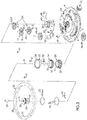
FIG.1 est une vue en perspective d'un mécanisme horloger à remontage automatique, équipé d'un rotor situé du côté de l'affichage ; - La
FIG.2 est une vue en perspective éclatée du mécanisme de laFIG.1 ; - La
FIG.3 est une vue similaire à laFIG.2 , montrant le mécanisme à plus grande échelle ; - La
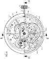
FIG.4 est une vue en plan du mécanisme de laFIG.1 ; - La
FIG.5 est une vue en coupe du mécanisme de laFIG.4 , selon le plan de couple A-A ; - La
FIG.6 est une vue en coupe du mécanisme de laFIG.4 , selon le plan de coupe B-B ; - La
FIG.7 est une vue en coupe partielle du mécanisme de laFIG.4 , selon le plan de coupe C-C.
- The
FIG. 1 is a perspective view of a self-winding watch mechanism, equipped with a rotor located on the display side; - The
FIG. 2 is an exploded perspective view of the mechanism of theFIG. 1 ; - The
FIG. 3 is a view similar to theFIG. 2 , showing the mechanism on a larger scale; - The
FIG. 4 is a plan view of the mechanism of theFIG. 1 ; - The
FIG. 5 is a sectional view of the mechanism of theFIG. 4 , according to the AA torque plan; - The
FIG. 6 is a sectional view of the mechanism of theFIG. 4 , according to the section plane BB; - The
FIG. 7 is a partial sectional view of the mechanism of theFIG. 4 , according to the CC section plane.
Sur la
Le mouvement 1 comprend, en premier lieu, une platine 2, qui se présente sous forme d'une pièce rigide (réalisée de préférence en métal, par ex. en acier), destinée à former support pour divers composants du mouvement, fixes ou mobiles. La platine 2 présente une face 3 inférieure et une face 4 supérieure, opposée à la face 3 inférieure.The
Le mouvement 1 comprend, en deuxième lieu, un barillet 5 monté en rotation par rapport à la platine 3 et pourvu d'une roue 6 dentée primaire. Le barillet comprend un arbre 7 de barillet par lequel le barillet est monté en rotation sur la platine 2, un tambour 8 de barillet, et un ressort de barillet (non représenté) solidaire, par une extrémité interne, de l'arbre 7 de barillet et, par une extrémité externe, du tambour 8 de barillet.The
Comme illustré notamment sur la
Le mouvement 1 comprend, en troisième lieu, un remontoir 10 qui comprend une tige 11 de remontoir portant, à une extrémité externe, une couronne 12 de remontoir. Le remontoir comprend un mécanisme 13 de remontage par lequel la tige 11 de remontoir engrène, dans une position de remontage, la roue 9 dentée secondaire du barillet 5 pour en assurer manuellement la rotation et ainsi armer le ressort.The
Le mouvement 1 comprend, en quatrième lieu, une chaussée 14 montée en rotation par rapport à la platine 2 autour d'un axe A central. La chaussée comprend un canon 15 des minutes qui porte une aiguille 16 des minutes.The
La chaussée 14 est en relation d'engrenage avec la roue 6 dentée primaire du barillet par l'intermédiaire d'un rouage 17 de minuterie.
Plus précisément, et selon un mode de réalisation illustré notamment sur la
More precisely, and according to one embodiment illustrated in particular on the
Le rouage 17 de minuterie est monté en rotation par rapport à la platine 2.The
Le mouvement 1 comprend, en cinquième lieu, un mobile 20 des heures, monté en rotation par rapport à la platine 2 autour de l'axe A central. Le mobile des heures comprend un canon 21 des heures qui porte une aiguille 22 des heures.The
Le mobile 20 des heures est en relation d'engrenage avec la chaussée 14. Plus précisément, et selon un mode de réalisation illustré sur la
Plus précisément, la pignonnerie 24 comprend :
- Une roue 24.1 des heures, qui engrène un pignon 19.2 de minuterie solidaire en rotation de la roue 19.1 de minuterie ;
- Un pignon 24.2 réducteur, solidaire en rotation de la roue 24.1 des heures ;
- Une roue 24.3 inverseuse, interposée entre le pignon 24.2 réducteur et le pignon 23 des heures.
- An hour wheel 24.1, which meshes with a timer pinion 19.2 integral in rotation with the timer wheel 19.1;
- A reducer pinion 24.2, integral in rotation with the 24.1 hour wheel;
- A 24.3 reversing wheel, interposed between the 24.2 reducer pinion and the 23 hour pinion.
On note :
- NM la vitesse de rotation du pignon 18 des minutes (et donc de l'aiguille 16 des minutes) ;
- NH la vitesse de rotation du pignon 23 des heures (et donc de l'aiguille 22 des heures) ;
- ZM le nombre de dents du pignon 18 des minutes ;
- ZH le nombre de dents du pignon 23 des heures ;
- Z1 le nombre de dents de la roue 19.1 de minuterie ;
- Z2 le nombre de dents du pignon 19.2 de minuterie ;
- Z3 le nombre de dents de la roue 24.1 des heures ;
- Z4 le nombre de dents du pignon 24.2 réducteur.
- N M the speed of rotation of the minute pinion 18 (and therefore of the minute hand 16);
- N H the speed of rotation of the
pinion 23 hours (and therefore of the 22 hour hand); - Z M the number of teeth of the
pinion 18 of the minutes; - Z H the number of teeth of the
pinion 23 of the hours; - Z1 the number of teeth of the timer wheel 19.1;
- Z2 the number of teeth of the timer pinion 19.2;
- Z3 the number of teeth of the wheel 24.1 hours;
- Z4 the number of teeth of the reducer pinion 24.2.
Le rapport R d'engrenage s'écrit : ![]()
![]()
Les engrenages sont choisis pour que le rapport R d'engrenage soit égal à 1/12. L'exemple suivant fournit un tel rapport R :
ZM = ZM = 64 ; Z1 = 60 ; Z2 = 16 ; Z3 = 48 ; Z4 = 15The gears are chosen so that the gear ratio R is equal to 1/12. The following example provides such an R report:
Z M = Z M = 64; Z1 = 60; Z2 = 16; Z3 = 48; Z4 = 15
La chaussée 14, incluant le canon 15 des minutes et l'aiguille 16 des minutes, est située du côté de la face 4 supérieure de la platine 2. De même, le mobile 20 des heures, incluant le canon 21 des heures et l'aiguille 22 des heures, est situé du côté de la face 4 supérieure de la platine 2.The
Le mouvement 1 comprend, en sixième lieu, une masse oscillante sous forme d'un rotor 25 monté en rotation par rapport à la platine 2 autour de l'axe A central, du même côté de la platine 2 que la chaussée 14 et le mobile 20 des heures - en l'espèce du côté de la face 4 supérieure de la platine.The
Comme illustré notamment sur la
- ∘ Un moyeu 26 central, en relation d'engrenage avec le barillet 5 ;
- ∘ Une jante 27 solidaire du moyeu 26 central ;
- ∘ Un secteur 28 annulaire lourd qui est solidaire de la jante 27.
- ∘ A
central hub 26, in gear relation with thebarrel 5; - ∘ A rim 27 integral with the
central hub 26; - ∘ A heavy
annular sector 28 which is integral with therim 27.
Selon un mode particulier de réalisation, illustré sur les dessins, la jante 27 se présente sous forme d'un disque plein, mais il pourrait être ajouré. Dans l'exemple de réalisation, la jante est un disque plein réalisé dans un matériau transparent, par ex. en saphir industriel.According to a particular embodiment, illustrated in the drawings, the
Le secteur 28 annulaire lourd se présente par ex. sous forme d'un demi-anneau réalisé dans un matériau dont la densité est supérieure à celle du matériau de la jante 27. Ainsi, selon un mode particulier de réalisation, le secteur annulaire lourd est réalisé en laiton.The heavy
La fixation du secteur 28 annulaire lourd à la jante 27 est par ex. réalisée par vissage, rivetage, sertissage ou encore collage.The attachment of the heavy
Le mouvement 1 comprend, en septième lieu, un arbre 29 rehausseur solidaire du moyeu 26 central et par lequel celui-ci est monté en rotation par rapport à la platine 2.The
L'arbre 29 rehausseur se présente de préférence sous forme d'un cylindre creux, réalisé par ex. en acier.The
L'arbre rehausseur et le moyeu central pourraient former une pièce monobloc. Cependant, dans l'exemple illustré, l'arbre rehausseur et le moyeu central forment deux pièces distinctes fixées l'une à l'autre. Selon un mode particulier de réalisation, le moyeu central est chassé sur une extrémité supérieure de l'arbre rehausseur.The booster shaft and the central hub could form a single piece. However, in the example illustrated, the booster shaft and the central hub form two separate parts fixed to one another. According to a particular embodiment, the central hub is driven onto an upper end of the booster shaft.
Comme on le voit bien sur la
Ainsi, tout en permettant au porteur de profiter du spectacle procuré par la rotation du rotor 25, cette disposition permet de positionner les aiguilles 16, 22 au plus près d'un éventuel cadran ou d'une couronne portant une graduation horaire, au bénéfice de la lisibilité des heures.Thus, while allowing the wearer to enjoy the spectacle provided by the rotation of the
Selon un mode préféré de réalisation, le mouvement 1 comprend un roulement 30 pourvu :
D'une bague 31 fixe par rapport à la platine 2,D'une bague 32 mobile en rotation par rapport à la bague 31 fixe autour de l'axe A central et dont est solidaire l'arbre 29 rehausseur, etD'éléments 33 roulants interposés entre les bagues 31, 32 (typiquement des billes).
- A
ring 31 fixed relative to theplate 2, - A
ring 32 movable in rotation with respect to thering 31 fixed around the central axis A and with which thebooster shaft 29 is integral, and -
Rolling elements 33 interposed between therings 31, 32 (typically balls).
Le roulement 30 est avantageusement monté sur un pont 34 intermédiaire fixé sur la platine 2.The
Dans l'exemple illustré, la bague 31 fixe est une bague intérieure du roulement 30, et la bague 32 mobile une bague extérieure.In the example illustrated, the fixed
Comme cela est bien visible sur les
- Renforcer l'arbre rehausseur en cas de chocs latéraux pouvant s'exercer sur le mouvement horloger,
- Absorber les éventuelles déformations dues au serrage de la vis 35 centrale sur la bague 31 intérieure, et ainsi garantir une bonne coaxialité de celle-ci avec l'axe A de rotation central.
- Reinforce the booster shaft in the event of side impacts that may be exerted on the watch movement,
- Absorb any deformations due to the tightening of the
central screw 35 on theinner ring 31, and thus guarantee good coaxiality of the latter with the central axis A of rotation.
Dans l'exemple illustré, l'arbre 29 rehausseur est chassé sur la bague 32 mobile située à l'extérieur du roulement.In the example illustrated, the
La bague 32 mobile porte de préférence une couronne 37 dentée en relation d'engrenage avec le barillet 5, par l'intermédiaire d'un rouage 38 réducteur (visible sur la
Comme on le voit bien sur les
Le mouvement 1 comprend avantageusement une douille 39 entourant l'arbre rehausseur, cette douille étant fixe par rapport à la platine 2. Le canon 20 des heures et le canon 15 des minutes sont montés sur la douille. Dans l'exemple illustré, la douille est solidaire (par ex. par chassage) d'un pont 40 supérieur fixé sur la platine 2. Plus précisément, dans l'exemple illustré, le pont supérieur est fixé sur le pont 34 intermédiaire.The
La bague 31 intérieure du roulement 30 est fixée au pont intermédiaire par la vis 35 centrale, cette vis centrale solidarisant en outre à ce pont la pièce 36 intermédiaire, laquelle présente un fond avec un trou central pour le passage de la vis centrale et un tube rigide dans lequel est situé la tête de cette vis centrale, ce tube rigide étant situé à l'intérieur d'une ouverture centrale que présente l'arbre rehausseur, cet arbre rehausseur formant un tube tournant.The
Le pont 40 supérieur est bien visible sur les
Selon un mode préféré de réalisation :
Le canon 21 des heures est emboîté sur la douille 39,Le canon 15 des minutes est emboîté sur lecanon 21 des heures.
- The
barrel 21 of the hours is fitted on thesleeve 39, - The 15 minute barrel is fitted onto the 21 hour barrel.
Un premier lanternage est avantageusement prévu à l'interface entre la douille 39 et le canon 21 des heures pour permettre la rotation de celui-ci (avec l'aiguille 22 des heures) par rapport à la douille.A first lanterning is advantageously provided at the interface between the
Un deuxième lanternage est avantageusement prévu à l'interface entre le canon 21 des heures et le canon 15 des minutes pour permettre la rotation de celui-ci (avec l'aiguille 16 des minutes) par rapport au canon des heures.A second lanterning is advantageously provided at the interface between the
Comme on le voit notamment sur la
Afin d'assurer la transmission de la rotation du barillet 5 (situé du côté de la face 44 interne du pont 40 supérieur) au rouage 17 de minuterie, le mouvement 1 est avantageusement équipé d'un mobile 46 inverseur, qui comprend :
- Une roue 47 supérieure située du côté de la
face 45 externe dupont 40 supérieur et en prise d'engrenage avec le rouage 17 de minuterie (et plus précisément avec le pignon 19.2 de minuterie) ; - Une roue 48 inférieure située du côté de la
face 44 interne dupont 40 supérieur, solidaire en rotation de la roue 47 supérieure et en relation d'engrenage avec la roue 6 dentée primaire du barillet 5 ; Un axe 49 reliant, au travers dupont 40 supérieur, la roue 47 supérieure et la roue 48 inférieure.
- An
upper wheel 47 located on the side of theouter face 45 of theupper bridge 40 and in mesh with the timer gear 17 (and more precisely with the timer pinion 19.2); - A
lower wheel 48 located on the side of theinternal face 44 of theupper bridge 40, integral in rotation with theupper wheel 47 and in gear relation with the primarytoothed wheel 6 of thebarrel 5; - An
axis 49 connecting, through theupper bridge 40, theupper wheel 47 and thelower wheel 48.
Selon un mode de réalisation illustré sur la
Comme illustré sur la
En outre, comme on le voit notamment sur les
Le mouvement qui vient d'être décrit procure en particulier les avantages mentionnés ci-après.The movement which has just been described provides in particular the advantages mentioned below.
Premièrement, le fait que le rotor 25 soit situé du même côté que l'affichage de l'heure (c'est-à-dire que les aiguilles 15, 22) permet au porteur de profiter du spectacle qu'offre le mouvement du rotor, ce que ne permet pas une disposition de celui-ci à l'opposé de l'affichage.First, the fact that the
Ensuite, et à l'inverse de la majorité des mouvements de ce type, le fait que le rotor 25 surmonte les aiguilles 15, 22 (ce qui est rendu possible notamment par la présence de l'arbre rehausseur) permet de positionner celles-ci au plus près du corps du mouvement et d'une graduation des heures pouvant être située sur la face arrière de ce corps, au bénéfice de la lisibilité de l'affichage.Then, and unlike the majority of movements of this type, the fact that the
Finalement, on notera que le mouvement horloger qui vient d'être décrit peut aisément présenter également un affichage de l'heure supplémentaire situé du côté de la face avant de la platine 2. Dans ce dernier cas, on aurait ainsi un double affichage de l'heure, le second affichage pouvant correspondre par exemple à un fuseau horaire différent de celui du premier affichage.Finally, it will be noted that the watch movement which has just been described can easily also have an additional time display located on the side of the front face of
Claims (12)
- Horological movement (1) with automatic winding, which comprises:- a plate (2),- a barrel (5) mounted such that it rotates relative to the plate (2) and supporting a primary toothed wheel (6),- a cannon-pinion (14) mounted such that it rotates relative to the plate about a central axis (A) and meshing with the primary toothed wheel (6) of the barrel (5) by way of a motion-work train (17), this cannon-pinion (14) comprising a minute pipe (15) which supports a minute hand (16),- an hour wheel set (20) mounted such that it rotates relative to the plate about said central axis and meshing with the cannon-pinion (14), this hour wheel set (20) comprising an hour pipe (21) which supports an hour hand (22),- an oscillating weight in the form of a rotor (25) mounted such that it rotates relative to the plate (2) about the central axis (A), on the same side of the plate as the cannon-pinion (14) and the hour wheel set (20), this rotor comprising:this horological movement being characterised in that it comprises a lifting arbor (29) rigidly connected to the central hub (26) and via which this hub is mounted such that it rotates relative to the plate (2); and in that the minute pipe and the hour pipe are mounted coaxially about the lifting arbor that passes therethrough, the minute hand and the hour hand being located between the plate (2) and the rim (27) of the rotor.∘ a central hub (26) that meshes with the barrel,∘ a rim (27) rigidly connected to the central hub,∘ a heavy annular sector (28) which is rigidly connected to the rim;
- Horological movement (1) according to claim 1, characterised in that it comprises a bearing (30) provided with a ring (31) that is fixed relative to the plate (2), a ring (32) that is capable of moving in rotation relative to the fixed ring (31) about the central axis (A), and rolling elements (33) inserted between the two rings; and in that the lifting arbor (29) is rigidly connected to the mobile ring.
- Horological movement (1) according to claim 2, characterised in that the ring (32) capable of moving in rotation supports a toothed transmission wheel (37) that meshes with the barrel (5) via a reduction gear train (38).
- Horological movement (1) according to claim 3, characterised in that the barrel (5) supports a secondary toothed wheel (9) that is separate from the primary toothed wheel (6) and with which the reduction gear train meshes.
- Horological movement (1) according to any of claims 2 to 4, characterised in that the bearing (30) is mounted on a bar (34) attached to the plate (2).
- Horological movement (1) according to any of claims 2 to 5, characterised in that the fixed ring (31) is an inner ring and the ring (32) capable of moving in rotation is an outer ring.
- Horological movement (1) according to claims 5 and 6, implemented together, characterised in that the inner ring (31) of the bearing (30) is attached to the bar (34) by a centre screw (35), this centre screw further engaging, with this bar, an intermediate part (36), which has a bottom with a central hole for the passage of the centre screw and a rigid tube wherein the head of this centre screw is located, this rigid tube being located inside a central opening in the lifting arbor, this lifting arbor forming a rotating tube.
- Horological movement (1) according to any of the preceding claims, characterised in that it comprises a socket (39) that is fixed relative to the plate (2) and on which the hour pipe (21) and the minute pipe (15) are mounted, this fixed socket surrounding the lifting arbor.
- Horological movement (1) according to claim 8, characterised in that:- the hour pipe (21) is slotted onto the socket (39),- the minute pipe (15) is slotted onto the hour pipe (21).
- Horological movement (1) according to claim 8 or claim 9, characterised in that the socket is mounted, such that it is fixed, on an upper bar (40), which is attached to the plate (2), this upper bar having an internal face (44) on the same side as the plate (2), and an opposite external face (45).
- Horological movement (1) according to claim 10, characterised in that the barrel (5) is mounted on the same side of the upper bar (40) as the internal face (44), whereas the cannon-pinion (14), the hour wheel set (20) and the rotor (25) are mounted on the same side of this upper bar as the external face.
- Horological movement (1) according to claim 11, characterised in that it comprises:- a motion-work train (17) meshing with a minute-pinion (18) rigidly connected to the minute pipe (15), which motion-work train is mounted such that it rotates relative to the upper bar (40) on the same side thereof as the external face (44),- a reverser wheel set (46), which comprises:∘ an upper wheel (47) located on the same side of the upper bar as the external face (45) and meshing with the motion-work train (17),∘ a lower wheel (48) located on the same side of the upper bar as the internal face (44) and rigidly connected to the upper wheel for rotation therewith and meshing with the primary toothed wheel (6) of the barrel (5),∘ a shaft (49) connecting, through the upper bar (40), the upper wheel to the lower wheel.
Priority Applications (4)
| Application Number | Priority Date | Filing Date | Title |
|---|---|---|---|
| EP18196380.2A EP3627232B1 (en) | 2018-09-24 | 2018-09-24 | Self-winding watch movement with time display hands located on the rotor side |
| US16/545,306 US11550260B2 (en) | 2018-09-24 | 2019-08-20 | Horological movement with automatic winding having time-displaying hands located on the same side as the rotor |
| JP2019166861A JP6728457B2 (en) | 2018-09-24 | 2019-09-13 | Timepiece movement with automatic winding function that has a time display hand located on the same side as the rotor |
| CN201910902745.XA CN110941171B (en) | 2018-09-24 | 2019-09-23 | Automatic winding timepiece movement with a time display hand located on the same side as the rotor |
Applications Claiming Priority (1)
| Application Number | Priority Date | Filing Date | Title |
|---|---|---|---|
| EP18196380.2A EP3627232B1 (en) | 2018-09-24 | 2018-09-24 | Self-winding watch movement with time display hands located on the rotor side |
Publications (2)
| Publication Number | Publication Date |
|---|---|
| EP3627232A1 EP3627232A1 (en) | 2020-03-25 |
| EP3627232B1 true EP3627232B1 (en) | 2021-05-05 |
Family
ID=63683106
Family Applications (1)
| Application Number | Title | Priority Date | Filing Date |
|---|---|---|---|
| EP18196380.2A Active EP3627232B1 (en) | 2018-09-24 | 2018-09-24 | Self-winding watch movement with time display hands located on the rotor side |
Country Status (4)
| Country | Link |
|---|---|
| US (1) | US11550260B2 (en) |
| EP (1) | EP3627232B1 (en) |
| JP (1) | JP6728457B2 (en) |
| CN (1) | CN110941171B (en) |
Family Cites Families (18)
| Publication number | Priority date | Publication date | Assignee | Title |
|---|---|---|---|---|
| CH426651A (en) * | 1964-12-10 | 1966-05-14 | Zenith Montres | Self-winding watch |
| CH685363B5 (en) * | 1993-05-21 | 1995-12-29 | Grandjean Eric M | Shows. |
| JPH1172580A (en) * | 1997-08-29 | 1999-03-16 | Seiko Instr Inc | Watch |
| JPH11183645A (en) * | 1997-12-18 | 1999-07-09 | Seiko Instruments Inc | Self-winding watch |
| CH692537A5 (en) * | 1998-10-23 | 2002-07-15 | Perrelet Sa | Watch mechanism having mechanical movement and automatic remounting oscillating weights upper/lower section held and teeth transmission connected teeth providing working reserve transmission. |
| JP2004170270A (en) | 2002-11-20 | 2004-06-17 | Seiko Instruments Inc | Self-winding watch having adjusting apparatus |
| JP4376536B2 (en) | 2003-03-27 | 2009-12-02 | セイコーインスツル株式会社 | Chronograph clock with hour / minute lever |
| JP4475630B2 (en) | 2004-01-27 | 2010-06-09 | セイコーインスツル株式会社 | Timepiece with mainspring winding state display including a deformed segment gear |
| WO2006103560A2 (en) * | 2005-03-30 | 2006-10-05 | Dth Dubois Technique Horlogere Sa | Self-winding device |
| DE102007046689B4 (en) * | 2007-06-01 | 2009-09-17 | Konrad Damasko | Mechanical lift for wristwatches and wristwatch with such a lift |
| EP2073078B1 (en) | 2007-12-21 | 2012-11-07 | Omega SA | Bistable hammer for a chronograph mechanism |
| CH703964B1 (en) | 2010-10-26 | 2015-07-15 | Soprod Sa | Automatic movement watch with oscillating weight arranged on the side of the plate. |
| CH705252B1 (en) * | 2011-07-07 | 2015-11-30 | Blancpain Sa | watch movement comprising means for displaying a physical quantity. |
| EP2551731A1 (en) | 2011-07-28 | 2013-01-30 | Cartier Création Studio S.A. | Pivoted oscillating weight on the outside of a clock movement and clock movement provided with such an oscillating weight. |
| CN204086820U (en) * | 2014-09-09 | 2015-01-07 | 杭州手表有限公司 | A kind of slim stem-winder annular automatic winding mechanism |
| EP3021173B1 (en) * | 2014-11-14 | 2017-05-24 | Blancpain S.A. | Annular oscillating mass and timepiece comprising such an oscillating mass |
| CH713222A1 (en) * | 2016-12-13 | 2018-06-15 | Cartier Int Ag | Watch movement with automatic winding. |
| CH713302A2 (en) * | 2016-12-23 | 2018-06-29 | Mft Et Fabrique De Montres Et Chronometres Ulysse Nardin Le Locle S A | Device for converting displacements, for example for automatic winding systems of timepieces. |
-
2018
- 2018-09-24 EP EP18196380.2A patent/EP3627232B1/en active Active
-
2019
- 2019-08-20 US US16/545,306 patent/US11550260B2/en active Active
- 2019-09-13 JP JP2019166861A patent/JP6728457B2/en active Active
- 2019-09-23 CN CN201910902745.XA patent/CN110941171B/en active Active
Also Published As
| Publication number | Publication date |
|---|---|
| JP2020052040A (en) | 2020-04-02 |
| US11550260B2 (en) | 2023-01-10 |
| EP3627232A1 (en) | 2020-03-25 |
| CN110941171B (en) | 2021-06-22 |
| US20200096942A1 (en) | 2020-03-26 |
| JP6728457B2 (en) | 2020-07-22 |
| CN110941171A (en) | 2020-03-31 |
Similar Documents
| Publication | Publication Date | Title |
|---|---|---|
| CH684619B5 (en) | Timepiece universal time display. | |
| EP1228403B1 (en) | Mechanically regulated timepiece | |
| EP1582943A1 (en) | Watch movement comprising several barrels | |
| EP1139182B1 (en) | Reserve power indicating mechanism and timepiece provided with such a mechanism | |
| CH693833A5 (en) | clockwork including a whirlpool. | |
| CH705832B1 (en) | Calendar mechanism and timepiece comprising such a mechanism. | |
| EP3627232B1 (en) | Self-winding watch movement with time display hands located on the rotor side | |
| EP3501842B1 (en) | Display device with rollers | |
| CH715378A2 (en) | Self-winding watch movement with time display hands located on the side of the oscillating weight. | |
| EP3246763B1 (en) | Quick correction mechanism for clock piece | |
| EP3555707B1 (en) | Automatic clock winding movement | |
| CH710450B1 (en) | Timepiece with orbital display. | |
| EP4080292B1 (en) | Timepiece mechanism for displaying at least a single indication of the time and timepiece comprising such a mechanism | |
| CH370709A (en) | Thin frame element for watch movement | |
| EP1353244B1 (en) | Timepiece with oblong shaped case | |
| CH333987A (en) | Watch with two pairs of hands | |
| CH682872B5 (en) | Timepiece comprising guide means of a control member such as a rod. | |
| CH717960B1 (en) | Horological mechanism for displaying the indication of the single time and timepiece comprising it. | |
| CH332539A (en) | Mechanism for driving the minute hand of a clockwork without a large mid-size wheel | |
| CH693291A5 (en) | Universal watch comprises first hour indicator and minute indicator operated by movement and comprising first tube wheel, second hour indicator fitted on second tube of second tube wheel | |
| CH700594B1 (en) | Horological movement for use in timepiece, has regulator mounted on transparent rotary disk and provided with axle shifted relative to rotation axis of disk, where disk carries peripheral teeth meshing with gear of finishing wheel | |
| CH332538A (en) | Mechanism for driving the minute hand of a clockwork without a large mid-size wheel | |
| CH712485A1 (en) | Watch movement. | |
| CH338777A (en) | 8-day watch movement, direct central seconds | |
| CH711246B1 (en) | Watch movement with vertical control rod. |
Legal Events
| Date | Code | Title | Description |
|---|---|---|---|
| PUAI | Public reference made under article 153(3) epc to a published international application that has entered the european phase |
Free format text: ORIGINAL CODE: 0009012 |
|
| STAA | Information on the status of an ep patent application or granted ep patent |
Free format text: STATUS: THE APPLICATION HAS BEEN PUBLISHED |
|
| AK | Designated contracting states |
Kind code of ref document: A1 Designated state(s): AL AT BE BG CH CY CZ DE DK EE ES FI FR GB GR HR HU IE IS IT LI LT LU LV MC MK MT NL NO PL PT RO RS SE SI SK SM TR |
|
| AX | Request for extension of the european patent |
Extension state: BA ME |
|
| STAA | Information on the status of an ep patent application or granted ep patent |
Free format text: STATUS: REQUEST FOR EXAMINATION WAS MADE |
|
| 17P | Request for examination filed |
Effective date: 20200925 |
|
| RBV | Designated contracting states (corrected) |
Designated state(s): AL AT BE BG CH CY CZ DE DK EE ES FI FR GB GR HR HU IE IS IT LI LT LU LV MC MK MT NL NO PL PT RO RS SE SI SK SM TR |
|
| GRAP | Despatch of communication of intention to grant a patent |
Free format text: ORIGINAL CODE: EPIDOSNIGR1 |
|
| STAA | Information on the status of an ep patent application or granted ep patent |
Free format text: STATUS: GRANT OF PATENT IS INTENDED |
|
| INTG | Intention to grant announced |
Effective date: 20210223 |
|
| GRAS | Grant fee paid |
Free format text: ORIGINAL CODE: EPIDOSNIGR3 |
|
| GRAA | (expected) grant |
Free format text: ORIGINAL CODE: 0009210 |
|
| STAA | Information on the status of an ep patent application or granted ep patent |
Free format text: STATUS: THE PATENT HAS BEEN GRANTED |
|
| AK | Designated contracting states |
Kind code of ref document: B1 Designated state(s): AL AT BE BG CH CY CZ DE DK EE ES FI FR GB GR HR HU IE IS IT LI LT LU LV MC MK MT NL NO PL PT RO RS SE SI SK SM TR |
|
| REG | Reference to a national code |
Ref country code: GB Ref legal event code: FG4D Free format text: NOT ENGLISH |
|
| REG | Reference to a national code |
Ref country code: CH Ref legal event code: EP Ref country code: CH Ref legal event code: NV Representative=s name: ICB INGENIEURS CONSEILS EN BREVETS SA, CH |
|
| REG | Reference to a national code |
Ref country code: AT Ref legal event code: REF Ref document number: 1390571 Country of ref document: AT Kind code of ref document: T Effective date: 20210515 |
|
| REG | Reference to a national code |
Ref country code: IE Ref legal event code: FG4D Free format text: LANGUAGE OF EP DOCUMENT: FRENCH |
|
| REG | Reference to a national code |
Ref country code: DE Ref legal event code: R096 Ref document number: 602018016535 Country of ref document: DE |
|
| REG | Reference to a national code |
Ref country code: LT Ref legal event code: MG9D |
|
| REG | Reference to a national code |
Ref country code: AT Ref legal event code: MK05 Ref document number: 1390571 Country of ref document: AT Kind code of ref document: T Effective date: 20210505 |
|
| PG25 | Lapsed in a contracting state [announced via postgrant information from national office to epo] |
Ref country code: FI Free format text: LAPSE BECAUSE OF FAILURE TO SUBMIT A TRANSLATION OF THE DESCRIPTION OR TO PAY THE FEE WITHIN THE PRESCRIBED TIME-LIMIT Effective date: 20210505 Ref country code: HR Free format text: LAPSE BECAUSE OF FAILURE TO SUBMIT A TRANSLATION OF THE DESCRIPTION OR TO PAY THE FEE WITHIN THE PRESCRIBED TIME-LIMIT Effective date: 20210505 Ref country code: LT Free format text: LAPSE BECAUSE OF FAILURE TO SUBMIT A TRANSLATION OF THE DESCRIPTION OR TO PAY THE FEE WITHIN THE PRESCRIBED TIME-LIMIT Effective date: 20210505 Ref country code: AT Free format text: LAPSE BECAUSE OF FAILURE TO SUBMIT A TRANSLATION OF THE DESCRIPTION OR TO PAY THE FEE WITHIN THE PRESCRIBED TIME-LIMIT Effective date: 20210505 Ref country code: BG Free format text: LAPSE BECAUSE OF FAILURE TO SUBMIT A TRANSLATION OF THE DESCRIPTION OR TO PAY THE FEE WITHIN THE PRESCRIBED TIME-LIMIT Effective date: 20210805 |
|
| PG25 | Lapsed in a contracting state [announced via postgrant information from national office to epo] |
Ref country code: IS Free format text: LAPSE BECAUSE OF FAILURE TO SUBMIT A TRANSLATION OF THE DESCRIPTION OR TO PAY THE FEE WITHIN THE PRESCRIBED TIME-LIMIT Effective date: 20210905 Ref country code: GR Free format text: LAPSE BECAUSE OF FAILURE TO SUBMIT A TRANSLATION OF THE DESCRIPTION OR TO PAY THE FEE WITHIN THE PRESCRIBED TIME-LIMIT Effective date: 20210806 Ref country code: PL Free format text: LAPSE BECAUSE OF FAILURE TO SUBMIT A TRANSLATION OF THE DESCRIPTION OR TO PAY THE FEE WITHIN THE PRESCRIBED TIME-LIMIT Effective date: 20210505 Ref country code: NO Free format text: LAPSE BECAUSE OF FAILURE TO SUBMIT A TRANSLATION OF THE DESCRIPTION OR TO PAY THE FEE WITHIN THE PRESCRIBED TIME-LIMIT Effective date: 20210805 Ref country code: LV Free format text: LAPSE BECAUSE OF FAILURE TO SUBMIT A TRANSLATION OF THE DESCRIPTION OR TO PAY THE FEE WITHIN THE PRESCRIBED TIME-LIMIT Effective date: 20210505 Ref country code: PT Free format text: LAPSE BECAUSE OF FAILURE TO SUBMIT A TRANSLATION OF THE DESCRIPTION OR TO PAY THE FEE WITHIN THE PRESCRIBED TIME-LIMIT Effective date: 20210906 Ref country code: SE Free format text: LAPSE BECAUSE OF FAILURE TO SUBMIT A TRANSLATION OF THE DESCRIPTION OR TO PAY THE FEE WITHIN THE PRESCRIBED TIME-LIMIT Effective date: 20210505 Ref country code: RS Free format text: LAPSE BECAUSE OF FAILURE TO SUBMIT A TRANSLATION OF THE DESCRIPTION OR TO PAY THE FEE WITHIN THE PRESCRIBED TIME-LIMIT Effective date: 20210505 |
|
| REG | Reference to a national code |
Ref country code: NL Ref legal event code: MP Effective date: 20210505 |
|
| PG25 | Lapsed in a contracting state [announced via postgrant information from national office to epo] |
Ref country code: NL Free format text: LAPSE BECAUSE OF FAILURE TO SUBMIT A TRANSLATION OF THE DESCRIPTION OR TO PAY THE FEE WITHIN THE PRESCRIBED TIME-LIMIT Effective date: 20210505 |
|
| PG25 | Lapsed in a contracting state [announced via postgrant information from national office to epo] |
Ref country code: RO Free format text: LAPSE BECAUSE OF FAILURE TO SUBMIT A TRANSLATION OF THE DESCRIPTION OR TO PAY THE FEE WITHIN THE PRESCRIBED TIME-LIMIT Effective date: 20210505 Ref country code: CZ Free format text: LAPSE BECAUSE OF FAILURE TO SUBMIT A TRANSLATION OF THE DESCRIPTION OR TO PAY THE FEE WITHIN THE PRESCRIBED TIME-LIMIT Effective date: 20210505 Ref country code: DK Free format text: LAPSE BECAUSE OF FAILURE TO SUBMIT A TRANSLATION OF THE DESCRIPTION OR TO PAY THE FEE WITHIN THE PRESCRIBED TIME-LIMIT Effective date: 20210505 Ref country code: SM Free format text: LAPSE BECAUSE OF FAILURE TO SUBMIT A TRANSLATION OF THE DESCRIPTION OR TO PAY THE FEE WITHIN THE PRESCRIBED TIME-LIMIT Effective date: 20210505 Ref country code: SK Free format text: LAPSE BECAUSE OF FAILURE TO SUBMIT A TRANSLATION OF THE DESCRIPTION OR TO PAY THE FEE WITHIN THE PRESCRIBED TIME-LIMIT Effective date: 20210505 Ref country code: EE Free format text: LAPSE BECAUSE OF FAILURE TO SUBMIT A TRANSLATION OF THE DESCRIPTION OR TO PAY THE FEE WITHIN THE PRESCRIBED TIME-LIMIT Effective date: 20210505 Ref country code: ES Free format text: LAPSE BECAUSE OF FAILURE TO SUBMIT A TRANSLATION OF THE DESCRIPTION OR TO PAY THE FEE WITHIN THE PRESCRIBED TIME-LIMIT Effective date: 20210505 |
|
| REG | Reference to a national code |
Ref country code: DE Ref legal event code: R097 Ref document number: 602018016535 Country of ref document: DE |
|
| PLBE | No opposition filed within time limit |
Free format text: ORIGINAL CODE: 0009261 |
|
| STAA | Information on the status of an ep patent application or granted ep patent |
Free format text: STATUS: NO OPPOSITION FILED WITHIN TIME LIMIT |
|
| 26N | No opposition filed |
Effective date: 20220208 |
|
| REG | Reference to a national code |
Ref country code: BE Ref legal event code: MM Effective date: 20210930 |
|
| PG25 | Lapsed in a contracting state [announced via postgrant information from national office to epo] |
Ref country code: IS Free format text: LAPSE BECAUSE OF FAILURE TO SUBMIT A TRANSLATION OF THE DESCRIPTION OR TO PAY THE FEE WITHIN THE PRESCRIBED TIME-LIMIT Effective date: 20210905 Ref country code: MC Free format text: LAPSE BECAUSE OF FAILURE TO SUBMIT A TRANSLATION OF THE DESCRIPTION OR TO PAY THE FEE WITHIN THE PRESCRIBED TIME-LIMIT Effective date: 20210505 Ref country code: AL Free format text: LAPSE BECAUSE OF FAILURE TO SUBMIT A TRANSLATION OF THE DESCRIPTION OR TO PAY THE FEE WITHIN THE PRESCRIBED TIME-LIMIT Effective date: 20210505 |
|
| PG25 | Lapsed in a contracting state [announced via postgrant information from national office to epo] |
Ref country code: LU Free format text: LAPSE BECAUSE OF NON-PAYMENT OF DUE FEES Effective date: 20210924 Ref country code: IT Free format text: LAPSE BECAUSE OF FAILURE TO SUBMIT A TRANSLATION OF THE DESCRIPTION OR TO PAY THE FEE WITHIN THE PRESCRIBED TIME-LIMIT Effective date: 20210505 Ref country code: IE Free format text: LAPSE BECAUSE OF NON-PAYMENT OF DUE FEES Effective date: 20210924 Ref country code: BE Free format text: LAPSE BECAUSE OF NON-PAYMENT OF DUE FEES Effective date: 20210930 |
|
| PG25 | Lapsed in a contracting state [announced via postgrant information from national office to epo] |
Ref country code: CY Free format text: LAPSE BECAUSE OF FAILURE TO SUBMIT A TRANSLATION OF THE DESCRIPTION OR TO PAY THE FEE WITHIN THE PRESCRIBED TIME-LIMIT Effective date: 20210505 |
|
| PG25 | Lapsed in a contracting state [announced via postgrant information from national office to epo] |
Ref country code: HU Free format text: LAPSE BECAUSE OF FAILURE TO SUBMIT A TRANSLATION OF THE DESCRIPTION OR TO PAY THE FEE WITHIN THE PRESCRIBED TIME-LIMIT; INVALID AB INITIO Effective date: 20180924 |
|
| P01 | Opt-out of the competence of the unified patent court (upc) registered |
Effective date: 20230701 |
|
| PGFP | Annual fee paid to national office [announced via postgrant information from national office to epo] |
Ref country code: GB Payment date: 20230823 Year of fee payment: 6 |
|
| PGFP | Annual fee paid to national office [announced via postgrant information from national office to epo] |
Ref country code: FR Payment date: 20230822 Year of fee payment: 6 Ref country code: DE Payment date: 20230822 Year of fee payment: 6 |
|
| PGFP | Annual fee paid to national office [announced via postgrant information from national office to epo] |
Ref country code: CH Payment date: 20231001 Year of fee payment: 6 |