EP3623267B9 - Dispositif de réglage d'un premier composant et d'un deuxième composant d'un moyen de transport des personnes et / ou des marchandises relatives les unes aux autres ainsi que moyen de transport des personnes et / ou des marchandises doté d'un tel dispositif - Google Patents
Dispositif de réglage d'un premier composant et d'un deuxième composant d'un moyen de transport des personnes et / ou des marchandises relatives les unes aux autres ainsi que moyen de transport des personnes et / ou des marchandises doté d'un tel dispositif Download PDFInfo
- Publication number
- EP3623267B9 EP3623267B9 EP18194099.0A EP18194099A EP3623267B9 EP 3623267 B9 EP3623267 B9 EP 3623267B9 EP 18194099 A EP18194099 A EP 18194099A EP 3623267 B9 EP3623267 B9 EP 3623267B9
- Authority
- EP
- European Patent Office
- Prior art keywords
- axis
- component
- adjusting element
- along
- adjusting
- Prior art date
- Legal status (The legal status is an assumption and is not a legal conclusion. Google has not performed a legal analysis and makes no representation as to the accuracy of the status listed.)
- Active
Links
- 230000033001 locomotion Effects 0.000 claims description 29
- 230000000903 blocking effect Effects 0.000 description 9
- 230000005540 biological transmission Effects 0.000 description 3
- 238000004519 manufacturing process Methods 0.000 description 2
- KJLPSBMDOIVXSN-UHFFFAOYSA-N 4-[4-[2-[4-(3,4-dicarboxyphenoxy)phenyl]propan-2-yl]phenoxy]phthalic acid Chemical compound C=1C=C(OC=2C=C(C(C(O)=O)=CC=2)C(O)=O)C=CC=1C(C)(C)C(C=C1)=CC=C1OC1=CC=C(C(O)=O)C(C(O)=O)=C1 KJLPSBMDOIVXSN-UHFFFAOYSA-N 0.000 description 1
- 230000001419 dependent effect Effects 0.000 description 1
- 238000006073 displacement reaction Methods 0.000 description 1
- 230000000694 effects Effects 0.000 description 1
- 210000003746 feather Anatomy 0.000 description 1
- 230000005484 gravity Effects 0.000 description 1
- 230000003993 interaction Effects 0.000 description 1
- 238000000034 method Methods 0.000 description 1
- 230000000284 resting effect Effects 0.000 description 1
- 230000000717 retained effect Effects 0.000 description 1
Images


Classifications
-
- B—PERFORMING OPERATIONS; TRANSPORTING
- B62—LAND VEHICLES FOR TRAVELLING OTHERWISE THAN ON RAILS
- B62D—MOTOR VEHICLES; TRAILERS
- B62D65/00—Designing, manufacturing, e.g. assembling, facilitating disassembly, or structurally modifying motor vehicles or trailers, not otherwise provided for
- B62D65/02—Joining sub-units or components to, or positioning sub-units or components with respect to, body shell or other sub-units or components
- B62D65/024—Positioning of sub-units or components with respect to body shell or other sub-units or components
- B62D65/026—Positioning of sub-units or components with respect to body shell or other sub-units or components by using a jig or the like; Positioning of the jig
-
- F—MECHANICAL ENGINEERING; LIGHTING; HEATING; WEAPONS; BLASTING
- F16—ENGINEERING ELEMENTS AND UNITS; GENERAL MEASURES FOR PRODUCING AND MAINTAINING EFFECTIVE FUNCTIONING OF MACHINES OR INSTALLATIONS; THERMAL INSULATION IN GENERAL
- F16B—DEVICES FOR FASTENING OR SECURING CONSTRUCTIONAL ELEMENTS OR MACHINE PARTS TOGETHER, e.g. NAILS, BOLTS, CIRCLIPS, CLAMPS, CLIPS OR WEDGES; JOINTS OR JOINTING
- F16B7/00—Connections of rods or tubes, e.g. of non-circular section, mutually, including resilient connections
-
- B—PERFORMING OPERATIONS; TRANSPORTING
- B62—LAND VEHICLES FOR TRAVELLING OTHERWISE THAN ON RAILS
- B62D—MOTOR VEHICLES; TRAILERS
- B62D65/00—Designing, manufacturing, e.g. assembling, facilitating disassembly, or structurally modifying motor vehicles or trailers, not otherwise provided for
- B62D65/02—Joining sub-units or components to, or positioning sub-units or components with respect to, body shell or other sub-units or components
- B62D65/024—Positioning of sub-units or components with respect to body shell or other sub-units or components
-
- B—PERFORMING OPERATIONS; TRANSPORTING
- B62—LAND VEHICLES FOR TRAVELLING OTHERWISE THAN ON RAILS
- B62D—MOTOR VEHICLES; TRAILERS
- B62D25/00—Superstructure or monocoque structure sub-units; Parts or details thereof not otherwise provided for
- B62D25/08—Front or rear portions
- B62D25/082—Engine compartments
- B62D25/085—Front-end modules
-
- B—PERFORMING OPERATIONS; TRANSPORTING
- B62—LAND VEHICLES FOR TRAVELLING OTHERWISE THAN ON RAILS
- B62D—MOTOR VEHICLES; TRAILERS
- B62D27/00—Connections between superstructure or understructure sub-units
- B62D27/06—Connections between superstructure or understructure sub-units readily releasable
- B62D27/065—Connections between superstructure or understructure sub-units readily releasable using screwthread
-
- B—PERFORMING OPERATIONS; TRANSPORTING
- B62—LAND VEHICLES FOR TRAVELLING OTHERWISE THAN ON RAILS
- B62D—MOTOR VEHICLES; TRAILERS
- B62D65/00—Designing, manufacturing, e.g. assembling, facilitating disassembly, or structurally modifying motor vehicles or trailers, not otherwise provided for
- B62D65/02—Joining sub-units or components to, or positioning sub-units or components with respect to, body shell or other sub-units or components
- B62D65/16—Joining sub-units or components to, or positioning sub-units or components with respect to, body shell or other sub-units or components the sub-units or components being exterior fittings, e.g. bumpers, lights, wipers, exhausts
-
- B—PERFORMING OPERATIONS; TRANSPORTING
- B66—HOISTING; LIFTING; HAULING
- B66F—HOISTING, LIFTING, HAULING OR PUSHING, NOT OTHERWISE PROVIDED FOR, e.g. DEVICES WHICH APPLY A LIFTING OR PUSHING FORCE DIRECTLY TO THE SURFACE OF A LOAD
- B66F3/00—Devices, e.g. jacks, adapted for uninterrupted lifting of loads
- B66F3/08—Devices, e.g. jacks, adapted for uninterrupted lifting of loads screw operated
-
- F—MECHANICAL ENGINEERING; LIGHTING; HEATING; WEAPONS; BLASTING
- F16—ENGINEERING ELEMENTS AND UNITS; GENERAL MEASURES FOR PRODUCING AND MAINTAINING EFFECTIVE FUNCTIONING OF MACHINES OR INSTALLATIONS; THERMAL INSULATION IN GENERAL
- F16B—DEVICES FOR FASTENING OR SECURING CONSTRUCTIONAL ELEMENTS OR MACHINE PARTS TOGETHER, e.g. NAILS, BOLTS, CIRCLIPS, CLAMPS, CLIPS OR WEDGES; JOINTS OR JOINTING
- F16B5/00—Joining sheets or plates, e.g. panels, to one another or to strips or bars parallel to them
- F16B5/02—Joining sheets or plates, e.g. panels, to one another or to strips or bars parallel to them by means of fastening members using screw-thread
- F16B5/0216—Joining sheets or plates, e.g. panels, to one another or to strips or bars parallel to them by means of fastening members using screw-thread the position of the plates to be connected being adjustable
- F16B5/0225—Joining sheets or plates, e.g. panels, to one another or to strips or bars parallel to them by means of fastening members using screw-thread the position of the plates to be connected being adjustable allowing for adjustment parallel to the plane of the plates
-
- F—MECHANICAL ENGINEERING; LIGHTING; HEATING; WEAPONS; BLASTING
- F16—ENGINEERING ELEMENTS AND UNITS; GENERAL MEASURES FOR PRODUCING AND MAINTAINING EFFECTIVE FUNCTIONING OF MACHINES OR INSTALLATIONS; THERMAL INSULATION IN GENERAL
- F16B—DEVICES FOR FASTENING OR SECURING CONSTRUCTIONAL ELEMENTS OR MACHINE PARTS TOGETHER, e.g. NAILS, BOLTS, CIRCLIPS, CLAMPS, CLIPS OR WEDGES; JOINTS OR JOINTING
- F16B5/00—Joining sheets or plates, e.g. panels, to one another or to strips or bars parallel to them
- F16B5/02—Joining sheets or plates, e.g. panels, to one another or to strips or bars parallel to them by means of fastening members using screw-thread
- F16B5/0216—Joining sheets or plates, e.g. panels, to one another or to strips or bars parallel to them by means of fastening members using screw-thread the position of the plates to be connected being adjustable
- F16B5/0233—Joining sheets or plates, e.g. panels, to one another or to strips or bars parallel to them by means of fastening members using screw-thread the position of the plates to be connected being adjustable allowing for adjustment perpendicular to the plane of the plates
Definitions
- the present invention relates to a device for adjusting a first component and a second component of a means of passenger and/or goods transport relative to one another. Furthermore, the invention relates to a means of transporting people and/or goods with such a device.
- the means of transporting people and/or goods is designed in particular as a vehicle, but can also be a ship, an airplane, a train or the like. If the invention is explained below in relation to vehicles, the statements also apply equally to other means of transporting people and/or goods such as ships, airplanes, trains or the like.
- the perceived quality which is particularly important as a sales argument for vehicles, is characterized, among other things, by an even and small dimension of the visible joints with which two adjacent components, for example the bonnet, headlights and bumper of vehicles, are arranged adjacent to one another. Due to fluctuations in production, however, the components are never exactly the same size, so that the gap dimensions are different for each vehicle. In order to nevertheless obtain a uniform joint dimension, the joint dimension is proceeded separately for each vehicle in the following way: At least one of the two adjacently arranged components is mounted on the vehicle so that it can move to a certain extent. The movement is usually generated by means of an eccentric disk between the movable component and a bracket on which the movable member is supported. By rotating the eccentric disc, the component in question can be moved towards or away from the component arranged adjacent to it. This allows the joint size to be adjusted.
- the eccentric disc In order to use the eccentric disc to move the relevant component towards or away from the adjacent component, a comparatively large amount of force is usually required, which must be applied by the relevant employee of the vehicle manufacturer.
- the eccentric disk usually has a socket for a wrench, with which the employee can apply the necessary force.
- the joint dimension has to be set very precisely, it can take a considerable amount of time to set the joint dimension as specified.
- the effectiveness of the eccentric disc is low.
- the eccentric disk tends to move as a result of the vibrations that occur during operation of the vehicle, which also changes the set gap dimension.
- the EP 2 683 596 A1 discloses a device for adjusting the gap size without an eccentric disk, but the device shown there cannot reliably prevent the gap size, once set, from changing during operation of the vehicle.
- the object of one embodiment of the present invention is to provide a device with which it is possible to set the joint dimension of a first component and a second component of a means of passenger and/or goods transport in a short time using simple and inexpensive means, with the joint dimension once set should also be maintained under the vibrations that occur during operation. Furthermore, an embodiment of the present invention is based on the object of providing a means of transporting people and/or goods with such a device.
- One embodiment of the invention relates to a device for adjusting a first component and a second component of a means of passenger and/or goods transport relative to one another, the two components being arranged adjacent to one another to form a joint, comprising a base body, a along a first axis and/or or adjustment element mounted in the base body so that it can move about the first axis, an adjusting body mounted in the base body so that it can move along a second axis, which interacts with the adjusting element in such a way that the movement of the adjusting element along the first axis or about the first axis results in a movement of the adjusting body and/or or the adjustment element is converted along the second axis, the movement of the adjustment body and/or the adjustment element along the second axis being transferrable to the first component or the second component, and a fixing device for fixing the adjustment element and the adjustment body in one selectable position.
- An adjustment element is to be understood as an element which can be actuated by a person, for example by an employee of the manufacturer of the means of passenger and/or goods transport or a repair shop, preferably using a suitable tool.
- the adjusting body converts the movement of the adjustment element along the first axis and/or around the first axis into a movement along the second axis.
- the proposed device has the fixing device with which the position of the adjusting element and the adjusting body can be fixed in a selectable position. It follows from this that the two components that can be moved relative to one another can no longer move relative to one another as soon as the position of the adjusting element and the adjusting body has been fixed.
- the dimensions of the joints in known means of transporting people and/or goods can change as a result of loads and vibrations occurring during operation.
- Such an adjustment during operation of the means of passenger and/or goods transport is prevented by the fixing device.
- the joint dimension that has been set is retained.
- the initially mentioned quality impression of the relevant means of passenger and/or goods transport does not deteriorate during operation with regard to the gap dimension.
- the adjusting element is designed as a screw with a screw head.
- Screws are a widely used means of converting rotary motion into linear motion. They are inexpensive to obtain and easy to use.
- the screw can be secured, for example, with spring washers or other screw locking elements, which in this case act as a fixing device.
- the fixing device is designed as a self-locking thread of the screw.
- the threads usually used in screws are self-locking anyway, although this does not rule out the possibility that the screws in question can turn uncontrollably during operation.
- the thread can be designed to be self-locking to a particular extent, for example in that the pitch of the thread is particularly small.
- the screw acts not only as the adjusting element, but also as the fixing device, so that the device according to this exemplary embodiment makes do with particularly few components and is therefore of low complexity.
- the actuating body is mounted in the base body so as to be rotatable about a pivot point, in particular about a pivot point directed perpendicularly to the first axis and to the second axis, in particular via an extension arm.
- the adjusting body has a first contact surface for being acted upon by the screw head of the screw, which is oriented substantially perpendicularly to the first axis, and a second Contact surface for contacting the first component or the second component, which is aligned substantially perpendicular to the second axis. In this way, a direction deflection of the adjustment movement is achieved in a simple manner.
- the base body has, in particular, an internal thread that fits the screw and is aligned in the direction of the first axis.
- the adjusting body has an opening for the screw to pass through, and the first contact surface is formed by the surface surrounding the opening.
- the adjusting body has at least two legs, in particular forming an approximately L-shaped adjusting body, which are angled to one another in the range of 45° to 135°, in particular approximately 90°, with the pivot point at the connection point of the two Leg is arranged and wherein the first contact surface is formed on the one leg and the second contact surface on the other leg.
- a further developed embodiment is characterized in that at least one, preferably both, of the first and second contact surfaces are convexly curved, which causes the respective contact surface to be aligned essentially perpendicular to the first axis or second axis even in different rotational positions around the pivot point. This improves the contact with the component or the screw.
- the first contact surface is arranged at a different, in particular smaller, distance from the pivot point than the second contact surface.
- the adjusting element can be designed as a screw, with the adjusting body being designed as an eccentric body arranged in particular in a stationary manner on the screw.
- the eccentric body makes it possible to design the adjusting body in a space-saving and simple manner. As a result, the entire device can be made compact and can also be arranged where the available space is limited.
- the eccentric body can have a helical bearing surface with a radius that changes in relation to the first axis, with the eccentric body being supported on a bearing section of the base body.
- the eccentric body is guided particularly well in relation to the base body, as a result of which the two components that are to be adjusted relative to one another can likewise be moved very precisely.
- the joint dimension can therefore be set very precisely.
- a further developed embodiment is characterized in that the fixing device comprises a friction section which is arranged on the base body and interacts with the eccentric body.
- the fixing device can be designed in a particularly simple manner, namely in that the eccentric body is pressed against the friction section of the base body. Consequently, a frictional force must be overcome, which prevents the screw from turning uncontrolled during operation of the passenger and/or goods transport means and the set joint dimension from changing.
- the adjusting element comprises a spindle and the adjusting body comprises a spindle nut arranged on the spindle and a pair of scissors with two scissor links, the spindle nut being fixed in a rotationally fixed manner to the pair of scissors, the first of the scissor links being rotatable on the base body and the the other of the scissor members is non-rotatably attached to a support body on which the first component or the second component can be placed, or the first of the scissor members is rotatably attached to the base body and the other of the scissor members is non-rotatably attached to the first component or the second component.
- the use of the pair of scissors makes it possible to move the component in question very precisely relative to the second component.
- the joint dimension can therefore be set very precisely.
- a further embodiment is characterized in that the adjusting element comprises a spindle and the adjusting body comprises a spindle wedge arranged on the spindle or around the spindle, and the base body has a wedge section corresponding to the spindle wedge, with the spindle wedge being supported on the wedge section or vice versa.
- the spindle wedge and the wedge section each have a very simple geometric shape, so that this embodiment is characterized by a simple shape.
- the spindle wedge and the corresponding wedge section act as the fixing device, since a particularly high frictional force acts between them, which prevents the joint dimension from being adjusted during operation.
- a further developed embodiment specifies that the fixing device has a locking element that is non-rotatable with the adjustment element and can be moved axially on the adjustment element, with the locking element between a locked position, in which the locking element blocks the rotation of the adjustment element about the first axis, and an open position, in which the locking element allows the rotation of the adjusting element, is axially displaceable.
- the employee when setting the joint dimension, the employee must first move the blocking element from the blocked position into the open position before he can move the two relevant components relative to one another and set the joint dimension. Once the intended joint dimension has been reached, the employee resets the blocking element to the blocking position, in which rotation of the adjustment element is prevented. As a result, it is also prevented that the two relevant components can be adjusted relative to each other during operation and the joint dimension changes.
- the adjusting element is designed as a gear wheel which is rotatably mounted in the base body and which is in meshing engagement with the adjusting body designed as a rack movable along the second axis.
- an intermediate gear rotatably mounted in the base body is arranged between the gear wheel and the toothed rack.
- the intermediate gear wheel also serves to increase the transmission ratios and thus make it particularly easy for the employee to set the joint dimension.
- the gear wheel is designed as a bevel gear.
- the accessibility of the adjustment element can be selected according to the requirements of the production.
- a further embodiment is characterized in that the gear wheel is mounted in the base body in an axially displaceable manner, the gear wheel between a blocked position, in which the rotation of the adjustment element about the first axis is blocked, and an open position, in which the rotation of the adjustment element is possible , is axially displaceable.
- the employee when setting the gap dimension, the employee must first move the gearwheel from the locked position to the open position before he can move the two relevant components relative to one another and adjust the gap dimension. Once the intended joint dimension has been reached, the employee puts the gear wheel back into the locked position, in which the adjustment element is prevented from rotating. As a result, the two are also prevented from each other affected components can be adjusted relative to each other during operation and the joint dimension changes.
- the base body has a locking section which corresponds to the gear wheel and in which the gear wheel engages in a form-fitting manner in the locked position.
- the blocking section can be manufactured particularly easily.
- One embodiment of the invention relates to a means of transporting people and/or goods, comprising a first component and a second component, the two components being arranged adjacent to one another to form a joint, and a device according to one of the previously explained embodiments, the first component and the second component can be adjusted relative to one another by means of the device, as a result of which the joint dimensions of the joint can be changed.
- the joint dimension can be set as specified with little effort, even if the component to be moved is relatively heavy.
- the fixing device prevents the joint dimension, once set, from changing in an uncontrolled manner as a result of the vibrations and loads occurring during operation of the passenger and/or goods transport means.
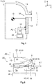
- a means of transporting people and/or goods 10 is shown on the basis of a basic representation, which has a first component 12 and a second component 14 .
- the means of transporting people and/or goods 10 should be designed as a vehicle 16, in particular as a motor vehicle, although the following embodiments essentially also apply to other embodiments of the means of transporting people and/or goods 10 such as trains, ships or airplanes apply equally.
- the first component 12 can be a bumper or a headlight, for example, whereas the second component 14 can be a hood, for example.
- the first component 12 and the second component 14 are arranged adjacent to form a joint 18 with the joint dimension G, the joint 18 being visible from the outside.
- the first component 12 is attached to the vehicle 16 so that it can rotate about an attachment point B, with an axially displaceable mounting also being conceivable.
- the first component 12 has a projection 20 which interacts with a device 22 according to the invention for adjusting the first component 12 relative to the second component 14 .
- the second component 14 should be located above the first component 12 in relation to the intended orientation of the vehicle 16 . Referring to figure 1 the device 22 is supported downwards on a carrier 24 of the vehicle 16 .
- the distance between the part of the first component 12 that forms the joint 18 and the fastening point B is selected such that actuation of the device 22 according to the invention mainly causes a movement of the first component 12 in the Z direction, as a result of which the joint dimension G of the joint 18 changes accordingly can be.
- the joint dimension G is usually less than 1 cm. Due to the fact that the second component 14 is arranged above the first component 12, the first component 12 must be moved against the force of gravity. Consequently, setting the gap dimension G is particularly difficult in this case.
- the device 22 according to the invention can equally be applied to the case in which the first component 12 and the second component 14 are arranged next to one another or in other orientations to one another.
- FIG 2 a first exemplary embodiment of the device 22 1 according to the invention is shown using a basic side view.
- the device 22 1 comprises a base body 26 which rests on the carrier 24 already mentioned, so that the device 22 1 can be supported on the carrier 24 .
- an extension arm 28 is fastened to the base body 26, to which an L-shaped adjusting body 30 is fastened so that it can rotate about a pivot point D, with the pivot point D also being able to be understood as an axis of rotation D.
- the cantilever 28 is designed as a separate component, although it can also be designed as an integral part of the base body 26, so that the base body 26 is in one piece.
- the device 22 1 rests at its upper end on the already described projection 20 of the first component 12 (see FIG figure 1 ).
- the device 22 1 according to the invention comprises an adjusting element 32 which is designed as a screw 34 which can be rotated about a first axis A1.
- the screw 34 is partially screwed into a threaded bore 36 arranged in the base body 26 .
- the screw 34 is pushed through a through hole 38 of the adjusting body 30 , the screw head 35 of the screw 34 resting against the adjusting body 30 .
- the adjusting body 30 has a first contact surface 37 for the screw head 35 of the screw 34 to act on, which is aligned essentially perpendicular to the first axis A1. Furthermore, the actuating body 30 has a second contact surface 39 for contacting the first component 12, which is aligned essentially perpendicular to the second axis A2.
- the adjusting body 30 has two legs 41, 43, which give the adjusting body 30 an approximately L-shaped design.
- the two legs 41, 43 are angled at approximately 90° to one another, with the pivot point D being arranged in the connection area of the two legs 41, 43 and with the first contact surface 37 being on one leg 41 and the second contact surface 39 being on the other leg 43 is trained.
- both the first contact surface 37 and the second contact surface 39 are convexly curved, which means that the respective contact surface 41, 43 is aligned essentially perpendicularly to the first axis A1 or second axis A2 even in different rotational positions about the pivot point D.
- the first contact surface 37 is arranged at a smaller distance from the pivot point D than the second contact surface 39.
- the device 22 1 has a fixing device 40 which causes the once set position of the adjustment element 32 and consequently of the adjusting body 30 to be fixed and not changed even under loads during operation of the vehicle 16 .
- the fixing device 40 comprises a self-locking thread 42 arranged on the screw 34, but it can be used alternatively or cumulatively include, for example, not shown spring washers or other screw locking elements.
- the procedure is as follows:
- the screw 34 is rotated with a suitable tool about the first axis A1.
- the screw 34 is screwed further into the threaded bore 36 or moved out of it, so that the screw 34 is moved along the first axis A1.
- the adjusting body 30 is caused to rotate.
- the pivot point D and the orientation of the adjusting body 30 are selected such that the rotary movement about the pivot point D in the area relevant here mainly has an axial movement of the adjusting body 30 along a second axis A2, which is perpendicular to the first axis A1.
- the second axis A2 coincides with the Z-direction.
- the rotation of the adjusting body 30 causes the first component 12 to move either towards the second component 14 or away from the second component 14 .
- the joint dimension G is reduced or increased. Consequently, it is possible to adjust the clearance G by turning the screw 34 as specified. Due to the fact that the screw 34 has the self-locking thread 42, it remains in a selected position without rotating in an uncontrolled manner, for example as a result of vibrations and loads that occur when the vehicle 16 is in operation. Once the joint dimension G has been set, it therefore does not change.
- FIG. 3A and 3B a second exemplary embodiment of the device 22 2 according to the invention is shown using a perspective illustration or a side view.
- the device 22 1 according to the invention according to the second exemplary embodiment essentially corresponds to the first exemplary embodiment, but in this case the cantilever 28 is designed in one piece with the base body 26 .
- a third exemplary embodiment of the device 22 3 according to the invention is shown using a side view.
- the basic structure of the device 22 1 according to the third exemplary embodiment is the same as that of the device 22 1 , 22 2 according to the first or second exemplary embodiment, however, the device 22 3 is mounted in the vehicle 16 rotated by 180°.
- the base body 26 is attached to the projection 20 of the first component 12 and is therefore not supported on the support 24 of the vehicle 16 .
- the adjusting body 30 is not in contact with the projection 20 of the first component 12, but rather with the support 24 of the vehicle 16.
- the setting of the gap dimension G takes place in the manner described above.
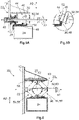
- FIG 5A a fourth exemplary embodiment of the device 22 4 according to the invention is shown using a side view.
- the adjusting body 30 is designed as a non-rotatable and axially non-displaceable eccentric body 44 fastened to the adjusting element 32, which is in turn designed as a screw 34 that can be rotated about the first axis A1.
- the eccentric body 44 has a helical bearing surface 46, the radius of which in relation to the first axis A1 and to the Figure 5A selected representation increases from left to right along the first axis A1.
- the base body 26 has a support section 48 with which the eccentric body 44 is in contact with the base body 26 with the support surface 46 .
- the screw 34 is screwed into an inserted into the first component 12 threaded sleeve 49, however, the pitch of the thread of the threaded sleeve 49 is the pitch of Bearing surface 46 of the eccentric body 44 adjusted so that in this embodiment, the thread of the threaded sleeve 49 can not be designed self-locking depending on the slope of the bearing surface 48. Consequently, depending on the design, the thread of the threaded sleeve 49 cannot assume the function of the fixing device 40 . In order nevertheless to prevent the screw 34 from rotating in an uncontrolled manner, the end of the eccentric body 44 pointing away from the threaded sleeve 49 rests against a friction section 50 which is formed by the base body 26 .
- the screw 34 is turned in one direction or the other about the first axis A1. As a result, the screw 34 is further moved into or out of the threaded sleeve 49 along the first axis A1. Due to the changing radius of the bearing surface 46, the first component 12 is thereby moved together with the screw 34 and the eccentric body 44 along the second axis A2 away from the base body 26 and the carrier 24 or towards the base body 26 and the carrier 24.
- the pitch of the thread of the threaded sleeve 49 is dimensioned in such a way that the bearing section 48 always remains on the bearing surface 46 of the eccentric body 44 .
- the eccentric body 44 has elevations 52 which delimit the bearing surface 46 towards its free end, as a result of which the bearing section 48 is guided on the bearing surface 46 .
- the friction section 50 of the base body 26 bears against the end of the eccentric body 44 pointing away from the threaded sleeve 49 . Due to the frictional force acting between the friction section 50 and the eccentric body 44, the screw 34 is prevented from being uncontrolled around the first Axis A1 rotates. Consequently, in this exemplary embodiment, the friction section 50 forms the fixing device 40.
- a fifth exemplary embodiment of the device 22 5 according to the invention is also shown in a side view.
- the adjusting body 30 comprises two pairs of scissors 54 , each of which has two scissor members 56 .
- the two lower scissor links 56 are rotatably connected to the base body 26 of the device 22 5 , which is on the in figure 1 shown carrier 24 of the vehicle 16 is supported.
- the two upper scissor links 56 are rotatably connected to a support body 58, which is also in figure 1 shown projection 20 of the first component 12 is fixed.
- the projection 20 can have fastening sections, not shown here, to which the two upper scissor elements 56 are fastened.
- the scissors members 56 of a pair of scissors 54 are rotatably connected to one another. All axes of rotation of the pairs of scissors 54 run parallel and in relation to the figure 6 selected representation perpendicular to the plane of the drawing.
- the adjusting element 32 comprises a spindle 60 which penetrates the two pairs of scissors 54 .
- a spindle nut 62 is screwed onto the spindle 60 and is non-rotatable with the in figure 6 left pair of scissors 54 connected.
- the spindle 60 is rotated in one direction or the other about the first axis A1.
- the spindle nut 62 is moved in one direction or the other axially along the first axis A1 and transmits this movement to the left pair of scissors 54. If the spindle 60 is moved so that the spindle nut 62 based on the figure 6 moved to the right, the angle enclosed by the two scissor elements 56 is increased, whereby the first component 12 is lifted along the second axis A2. As a result, the joint dimension G is reduced.
- the spindle 60 In order to prevent the spindle 60 itself from moving along the first axis A1, it has a diameter enlargement 63 which can be designed, for example, in the manner of a locking ring, with which the spindle 60 rests on the right-hand pair of scissors 54.
- a second spindle nut 62 (not shown here) can be provided, which moves in a direction toward or away from the first spindle nut 62 when the spindle 60 rotates.
- Such a movement can be achieved, for example, in that the spindle 60 has two thread sections, of which one thread section has a positive pitch and the other thread section has a negative pitch.
- the spindle 60 has a self-locking thread 42, which in this exemplary embodiment represents the fixing device 40 and prevents the spindle 60 from being able to rotate about its own axis A1 in an uncontrolled manner.
- FIG 7 a sixth exemplary embodiment of the device 22 6 according to the invention is shown using a side view.
- the device 22 1 according to the sixth exemplary embodiment has a spindle 60 and a spindle wedge 64 arranged on the spindle 60 .
- the spindle 60 forms the adjusting element 32 and the spindle wedge 64 forms the adjusting body 30.
- the spindle wedge 64 is designed in the manner of a spindle nut 62, but has an inclined surface 66. With this inclined surface 66, the spindle wedge 64 rests on a wedge section 68 of the base body 26, which is designed to correspond to the spindle wedge 64 and, in particular, has the same inclination.
- the spindle wedge 64 moves along the Axis of rotation of the spindle 60 or the first axis A1, whereby the first component 12 is moved together with the spindle 60 and the spindle wedge 64 along the second axis A2 towards the second component 14 or away from the second component 14, whereby the joint dimension G changes accordingly becomes.
- the projection 20 is formed in an L-shape. In relation to the first axis A1, the spindle 60 rests on the one hand against the free leg of the L-shaped projection 20 and on the other hand against the first component 12.
- a seventh exemplary embodiment of the device 22 7 according to the invention is shown in a side view.
- the seventh exemplary embodiment is largely the same as that in FIG figure 7 illustrated sixth embodiment, but the base body 26 is not on the carrier 24, but on the projection 20 of the first component 12 is arranged.
- the spindle wedge 64 which in Figure 8B shown separately by means of a perspective view, rests on the carrier 24 and with the inclined surface 66 on the wedge section 68 of the base body 26 .
- the spindle wedge 64 has no thread with which it interacts with the spindle 60 .
- the movement of the spindle key 64 along the first axis A1 is effected instead with the spindle nut 62 which is screwed onto the spindle 60 and which is connected to the spindle key 64 in a rotationally fixed manner. If the spindle 60 is rotated, the spindle wedge 64 is moved by means of the spindle nut 62 not only relative to the wedge section 68 of the base body 26, but also relative to the carrier 24 along the first axis A1. As in the sixth exemplary embodiment, the spindle 60 is attached to the first component 12 in such a way that it cannot move along the first axis A1.
- the base body 26 is L-shaped designed so that the spindle 60 is also secured on the free leg against displacement along the first axis A1.
- the spindle wedge 64 acts as the fixing device 40.
- a frictional force also acts between the spindle wedge 64 and the carrier 24, so that the position of the once adjusted Adjusting element 32 and the adjusting body 30, in this case the spindle wedge 64, is additionally fixed.
- the adjustment element 32 is designed as a gear wheel 70 which has an engagement section 74 designed as a hexagon 72 in the exemplary embodiment shown, into which a correspondingly shaped tool can be inserted.
- the gear 70 to the perpendicular to the plane of the Figure 9A running first axis A1 are rotated.
- the gear wheel 70 meshes with an intermediate gear wheel 76 which can be rotated about a further axis of rotation T running parallel to the first axis A1 of the first gear wheel 70 .
- the other gear 70 is in meshing engagement with a rack 78 which is axially movable perpendicular to the first axis A1 and the further axis of rotation T along the second axis A2.
- the toothed rack 78 is connected to the first component 12 (not shown here), so that a rotation of the gear wheel 70 about the first axis A1 causes the first component 12 to move toward the second component 14 in or away from the second component 14.
- gear wheel 70 is shown in an open position, in which the rotation of the gear wheel 70 about the first axis A1 is possible, in Figure 9C gear 70 is shown in a locked position in which rotation of gear 70 is locked.
- gear wheel 70 is mounted in the base body 26 so that it can move axially along the first axis A1. Both in the open position and in the locked position, the gear wheel 70 remains in meshing engagement with the intermediate gear wheel 76 .
- the base body 26 has a blocking section 80 which is designed to correspond to the gear wheel 70 .
- the gear wheel 70 engages in a form-fitting manner in the locking section 80, as a result of which the rotation of the gear wheel 70 about its own axis of rotation or about the first axis A1 is prevented.
- the first member 12 cannot be moved toward or away from the second member 14 along the second axis A2 when the gear 70 is in the locked position. Consequently, in this embodiment, the fixing device 40 is formed in the form of the locking portion 80 .
- a ninth exemplary embodiment of the device 22 9 according to the invention is shown on the basis of various views.
- the basic structure of the device 22 9 according to the ninth embodiment corresponds to the structure of the device 22 8 according to the eighth embodiment, but the gear 70 is designed as a bevel gear 82 in this case. Consequently, the first axis A1 and the further axis of rotation T do not run parallel to one another, but enclose an angle.
- the fixing device 40 is constructed somewhat differently. Due to the fact that the gear 70 is formed as a bevel gear 82, it cannot be moved axially along the first axis A1 without losing mesh with the intermediate gear 76.
- the fixing device 40 has a blocking element 84 which is axially displaceable on a bearing axis 86 connected to the bevel gear 82 in a torque-proof manner, but is connected to the bearing axis 86 in a torque-proof manner.
- the blocking element 84 is prestressed in a blocking position by means of a spring 88 .
- the blocking element 84 can be designed in the manner of a toothed wheel 70, but can also have a polygonal cross section.
- the locking element 84 engages in a form-fitting manner in a corresponding locking section 80 of the base body 26, so that the locking element 84 and consequently the gear wheel 70 cannot be rotated about the first axis A1.
- the first component 12 cannot be moved toward or away from the second component 14 along the second axis A2.
- the locking element 84 can be moved against the spring force applied by the spring 88 by means of a wrench 90 into the open position in which the gear 70 can be rotated and consequently the first component 12 can be moved towards or away from the second component 14.
- the wrench 90 only has to be pulled out of the gear wheel 70, whereby the gear wheel 70 is released from the spring 88 again is placed in the locked position. This fixes the joint dimension G once it has been set.
Claims (15)
- Dispositif de réglage l'un par rapport à l'autre, d'un premier composant (12) et d'un second composant (14) d'un moyen de transport de personnes et/ou de marchandises (10), les deux composants (12, 14) étant installés au voisinage l'un de l'autre en laissant un intervalle (18), dispositif comprenant :- une base (26),- un élément de réglage (32) monté dans la base (26), mobile le long et/ou autour d'un premier axe (A1),- un organe réglable (30) monté mobile le long d'un second axe (A2) dans le corps de base (26), cet organe réglable coopérant avec l'élément de réglage (32) pour que le mouvement de l'élément de réglage (32) le long du premier axe (A1) ou autour du premier axe (A1) se transforme en un mouvement de l'organe réglable (30) et/ou de l'élément de réglage (32) le long du second axe (A2) le mouvement de l'organe de réglage (30) et/ou de l'élément de réglage (32) le long du deuxième axe (A2) se transmettant au premier composant (12) ou au second composant (14), et- une installation de fixation (40) pour fixer l'élément réglable (32) et l'organe de réglage (30) dans une position sélectionnée,- l'élément de réglage (32) étant sous la forme d'une vis (34),dispositif caractérisé en ce que
l'installation de fixation (40) est sous la forme d'un filetage (42) autobloquant de la vis (34) avec une tête de vis (35). - Dispositif selon la revendication 1,
caractérisé en ce que
l'organe réglable (30) est monté à rotation dans la base (26) autour d'un point de rotation (D) en particulier par un bras (28), notamment autour d'un point de rotation (D) perpendiculaire au premier axe (A1) et au second axe (A2), et- l'organe réglable (30) ayant une première surface de contact (37) pour être sollicitée par la tête (35) de la vis (34), cette surface étant pratiquement perpendiculaire au premier axe (A1), et- l'organe réglable (30) a une seconde surface de contact (39) pour venir en contact avec le premier composant (12) ou le second composant (14), cette surface étant pratiquement perpendiculaire au second axe (A2). - Dispositif selon la revendication 2,
caractérisé en ce quel'organe réglable (30) comporte au moins deux branches (41, 43) formant notamment un organe réglable (30) sensiblement en forme de L, les branches étant repliées l'une par rapport à l'autre dans une plage comprise entre 45° et 135°, notamment d'environ 90°,le point de rotation (D) associé au point de jonction des deux branches (41, 43) et la première surface de contact (37) est réalisée sur une branche (41) et la seconde surface de contact (39) est réalisée sur l'autre branche (43). - Dispositif selon l'une des revendications 2 ou 3, caractérisé en ce que
au moins l'une et de préférence les deux première et seconde surfaces de contact (37, 39) sont bombées de forme convexe, de façon que même dans différentes positions de rotation autour du point de rotation (D), les surfaces de contact (41, 43) respectives restent essentiellement perpendiculaires au premier axe (A1) ou au second axe (A2). - Dispositif selon l'une des revendications 2 à 4, caractérisé en ce que
la première surface de contact (37) est à une autre distance par rapport au point de rotation (D) notamment plus faible que celle de la seconde surface de contact (39). - Dispositif de réglage l'un par rapport à l'autre d'un premier composant (12) et d'un second composant (14) d'un moyen de transport de personnes et/ou de marchandises (10) les deux composants (12, 14) étant voisins l'un à l'autre en laissant un intervalle (18),
dispositif comprenant :- une base (26),- un élément de réglage (32) monté mobile le long d'un premier axe (A1) et/ou autour d'un premier axe dans la base (26),- un organe réglable (30) monté mobile dans la base (26) le long d'un second axe (A2), cet organe réglable coopérant avec l'élément de réglage (32) pour que le mouvement de l'élément de réglage (32) le long du premier axe (A1) ou autour du premier axe (A1) se traduise par un mouvement de l'organe réglable (30) et/ou de l'élément de réglage (32) le long du second axe (A2), le mouvement de l'organe réglable (30) et/ou l'élément de réglage (32) le long du second axe (A2) étant transmis au premier composant (12) ou au second composant (14), et- une installation de fixation (40) est prévue pour fixer l'élément de réglage (32) et l'organe réglable (30) dans une position choisie,dispositif caractérisé en ce que
l'élément de réglage (32) est sous la forme d'une vis (34), l'organe réglable (30) étant réalisé sous la forme d'un excentrique (44) coopérant avec la vis (34). - Dispositif selon l'une la revendication 6,
caractérisé en ce que
l'excentrique (44) a une surface d'appui (46) hélicoïdale, à rayon variable par rapport au premier axe (A1), l'excentrique (44) s'appuyant sur un segment d'appui (48) de la base (26). - Dispositif selon l'une des revendications 6 ou 7, caractérisé en ce que
l'installation de fixation (40) comprend un segment de friction (50) prévu sur la base (26) et coopérant avec l'excentrique (44). - Dispositif de réglage l'un par rapport à l'autre d'un premier composant (12) et d'un second composant (14) d'un moyen de transport de personnes et/ou de marchandises (10) les composants (12, 14) étant installés au voisinage l'un de l'autre en laissant un intervalle (18), comprenant :- une base (26),- un élément de réglage (32) monté dans la base (26), mobile le long et/ou autour d'un premier axe (A1),- un organe réglable (30) monté mobile le long d'un second axe (A2) dans le corps de base (26), cet organe réglable coopérant avec l'élément de réglage (32) pour que le mouvement de l'élément de réglage (32) le long ou autour du premier axe (A1) se transforme en un mouvement de l'organe réglable (30) et/ou de l'élément de réglage (32) le long du second axe (A2), le mouvement de l'organe de réglage (30) et/ou de l'élément de réglage (32) le long du deuxième axe (A2) se transmettant au premier composant (12) ou au second composant (14), et- une installation de fixation (40) pour fixer l'élément réglable (32) et l'organe de réglage (30) dans une position sélectionnée,caractérisé en ce quel'élément de réglage (32) comprend une broche (60) et l'organe réglable (30) comprend un écrou (62) installé sur la broche (60) et une paire de ciseaux (54) avec deux éléments de ciseaux (56), l'écrou (62) étant fixé solidairement en rotation à la paire de ciseaux (54),le premier des éléments de ciseaux (56) étant fixé à rotation à la base (26) et l'autre des éléments de ciseaux (56) étant fixé solidairement en rotation à un organe d'appui (58) recevant le premier composant (12) ou le second composant (14), oule premier élément de ciseaux (56) est fixé à rotation à la base (26) et l'autre élément de ciseaux (56) est fixé solidairement en rotation au premier composant (12) ou au second composant (14).
- Dispositif de réglage l'un par rapport à l'autre d'un premier composant (12) et d'un second composant (14) d'un moyen de transport de personnes et/ou de marchandises (10), les deux composants (12, 14) étant installés au voisinage l'un de l'autre en laissant un intervalle (18), dispositif comprenant :- une base (26),- un élément de réglage (32) monté dans la base (26), mobile le long et/ou autour d'un premier axe (A1),- un organe réglable (30) monté mobile le long d'un second axe (A2) dans le corps de base (26), cet organe réglable coopérant avec l'élément de réglage (32) pour que le mouvement de l'élément de réglage (32) le long ou autour du premier axe (A1) se transforme en un mouvement de l'organe réglable (30) et/ou de l'élément de réglage (32) le long du second axe (A2) le mouvement de l'organe de réglage (30) et/ou de l'élément de réglage (32) le long du deuxième axe (A2) se transmettant au premier composant (12) ou au second composant (14), et- une installation de fixation (40) pour fixer l'élément réglable (32) et l'organe de réglage (30) dans une position sélectionnée,dispositif caractérisé en ce que
l'élément de réglage (32) est un pignon denté (70) monté à rotation dans la base (26) et en prise avec un organe réglable (30) en forme de crémaillère (78) mobile le long du second axe (A2) et un pignon intermédiaire (76) monté à rotation dans la base (26) est prévu entre le pignon denté (70) et la crémaillère (78). - Dispositif selon la revendication 10,
caractérisé en ce que
l'installation de fixation (40) comprend un élément de blocage (84) solidaire en rotation de l'élément de réglage (32) et coulissant axialement sur l'élément de réglage (32), l'élément de blocage (84) étant coulissant axialement entre une position de blocage dans laquelle l'élément de blocage (84) bloque le mouvement de rotation de l'élément de réglage (32) autour du premier axe (A1) et une position ouverte dans laquelle l'élément de blocage (84) permet la rotation de l'élément de réglage (32). - Dispositif selon l'une des revendications 10 ou 11, caractérisé en ce que
le pignon (70) est sous la forme d'un pignon conique (82). - Dispositif selon la revendication 12,
caractérisé en ce que
le pignon (70) est monté coulissant axialement dans la base (26), le pignon (70) étant coulissant axialement entre une position de blocage dans laquelle la rotation de l'élément de réglage (32) est bloquée autour du premier axe (A1) et une position ouverte dans laquelle la rotation de l'élément de réglage (32) est possible. - Dispositif selon l'une des revendications 10 ou 11, caractérisé en ce que
le corps de base (26) a un segment de blocage (80) correspondant au pignon (70) et le pignon (70) engrène par une liaison par la forme en position de blocage. - Moyen de transport de personnes et/ou de marchandises comprenant :- un premier composant (12) et un second composant (14), les deux composants (12, 14) étant voisins l'un de l'autre en laissant un intervalle (18), et- un dispositif (22) selon l'une des revendications précédentes, le premier composant (12) et le second composant (14) étant réglables l'un par rapport à l'autre par le dispositif (22), de façon à modifier la dimension (G) de l'intervalle (18).
Priority Applications (4)
| Application Number | Priority Date | Filing Date | Title |
|---|---|---|---|
| ES18194099T ES2921925T3 (es) | 2018-09-12 | 2018-09-12 | Dispositivo para el ajuste de un primer componente y un segundo componente de un medio de transporte de personas y/o de mercancías uno respecto a otro, así como medio de transporte de personas y/o de mercancías con un dispositivo de este tipo |
| EP18194099.0A EP3623267B9 (fr) | 2018-09-12 | 2018-09-12 | Dispositif de réglage d'un premier composant et d'un deuxième composant d'un moyen de transport des personnes et / ou des marchandises relatives les unes aux autres ainsi que moyen de transport des personnes et / ou des marchandises doté d'un tel dispositif |
| CN201910861299.2A CN110894843A (zh) | 2018-09-12 | 2019-09-12 | 用于将第一构件和第二构件相对彼此进行调节的装置 |
| US16/568,494 US20200079450A1 (en) | 2018-09-12 | 2019-09-12 | Device for adjusting a first component and a second component relative to each other in a passenger or freight transport means and a passenger and/or freight transport means with such a device |
Applications Claiming Priority (1)
| Application Number | Priority Date | Filing Date | Title |
|---|---|---|---|
| EP18194099.0A EP3623267B9 (fr) | 2018-09-12 | 2018-09-12 | Dispositif de réglage d'un premier composant et d'un deuxième composant d'un moyen de transport des personnes et / ou des marchandises relatives les unes aux autres ainsi que moyen de transport des personnes et / ou des marchandises doté d'un tel dispositif |
Publications (3)
| Publication Number | Publication Date |
|---|---|
| EP3623267A1 EP3623267A1 (fr) | 2020-03-18 |
| EP3623267B1 EP3623267B1 (fr) | 2022-04-06 |
| EP3623267B9 true EP3623267B9 (fr) | 2022-07-27 |
Family
ID=63637659
Family Applications (1)
| Application Number | Title | Priority Date | Filing Date |
|---|---|---|---|
| EP18194099.0A Active EP3623267B9 (fr) | 2018-09-12 | 2018-09-12 | Dispositif de réglage d'un premier composant et d'un deuxième composant d'un moyen de transport des personnes et / ou des marchandises relatives les unes aux autres ainsi que moyen de transport des personnes et / ou des marchandises doté d'un tel dispositif |
Country Status (4)
| Country | Link |
|---|---|
| US (1) | US20200079450A1 (fr) |
| EP (1) | EP3623267B9 (fr) |
| CN (1) | CN110894843A (fr) |
| ES (1) | ES2921925T3 (fr) |
Family Cites Families (7)
| Publication number | Priority date | Publication date | Assignee | Title |
|---|---|---|---|---|
| DE19612479A1 (de) * | 1996-03-29 | 1997-12-11 | Ymos Ag Ind Produkte | Verfahren und Vorrichtung zum Einstellen und lagegenauen Befestigen eines Kraftfahrzeug-Bauteiles |
| JP3843968B2 (ja) * | 2003-06-24 | 2006-11-08 | 日産自動車株式会社 | ヘッドランプの車体位置決め方法および車体位置決め構造 |
| FR2858290B1 (fr) * | 2003-07-30 | 2005-10-28 | Faurecia Ind | Ensemble de bloc-avant de vehicule automobile comportant des moyens d'ajustement de la position des blocs optiques, outil de reglage prevu a cet effet, et procede de montage d'un tel bloc-avant |
| EP2683596B1 (fr) * | 2011-03-07 | 2015-06-24 | Faurecia Exteriors GmbH | Support multifonction pour un véhicule à moteur |
| FR2973326B1 (fr) * | 2011-04-01 | 2013-04-05 | Peugeot Citroen Automobiles Sa | Systeme de positionnement d'un profile sur un element de caisse d'un vehicule |
| EP2873591B1 (fr) * | 2013-11-14 | 2017-09-06 | Compagnie Plastic Omnium | Ensemble réglable d'un panneau de carrosserie mobile avec un panneau de carrosserie fixe |
| DE102016014120A1 (de) * | 2016-11-26 | 2018-05-30 | GM Global Technology Operations LLC (n. d. Ges. d. Staates Delaware) | Justiervorrichtung und damit ausgestattetes Fahrzeug |
-
2018
- 2018-09-12 ES ES18194099T patent/ES2921925T3/es active Active
- 2018-09-12 EP EP18194099.0A patent/EP3623267B9/fr active Active
-
2019
- 2019-09-12 US US16/568,494 patent/US20200079450A1/en not_active Abandoned
- 2019-09-12 CN CN201910861299.2A patent/CN110894843A/zh active Pending
Also Published As
| Publication number | Publication date |
|---|---|
| US20200079450A1 (en) | 2020-03-12 |
| EP3623267A1 (fr) | 2020-03-18 |
| CN110894843A (zh) | 2020-03-20 |
| ES2921925T3 (es) | 2022-09-02 |
| EP3623267B1 (fr) | 2022-04-06 |
Similar Documents
| Publication | Publication Date | Title |
|---|---|---|
| DE3723204C2 (de) | Verstellvorrichtung für einen Sitz, insbesondere Kraftfahrzeugsitz, zur Neigungseinstellung der Rückenlehne | |
| DE202004016321U1 (de) | Zug-Druck-Stange | |
| EP3708753B1 (fr) | Ferrure de couvercle destinée à la fixation pivotante d'un couvercle de meuble sur un corps de meuble | |
| DE3412139A1 (de) | Stellmechanismus | |
| WO2012120079A1 (fr) | Volant pour véhicule automobile | |
| EP2864652B1 (fr) | Ensemble palier | |
| DE102015000452A1 (de) | Vorrichtung zur Unterstützung und Erleichterung des Öffnens und Schließens für ein Fenster oder eine Tür | |
| DE102018219264A1 (de) | Verstellantrieb für eine Lenksäule und Lenksäule für ein Kraftfahrzeug | |
| DE102020207636A1 (de) | Bidirektionales türöffnungsmodul | |
| DE19528789C1 (de) | Verschlußanordnung für ein bewegliches Karosserieteil | |
| EP3623267B9 (fr) | Dispositif de réglage d'un premier composant et d'un deuxième composant d'un moyen de transport des personnes et / ou des marchandises relatives les unes aux autres ainsi que moyen de transport des personnes et / ou des marchandises doté d'un tel dispositif | |
| EP3752694B1 (fr) | Dispositif de stationnement de voiture | |
| DE102017212073A1 (de) | Zahnstangengetriebe für ein Kraftfahrzeug | |
| EP3523160B1 (fr) | Agencement de transmission pour mécanisme d'entraînement de broche, entraînement de broche et siège de véhicule | |
| EP1375803A1 (fr) | Charnière de porte notamment pour véhicules automobile | |
| EP0875439A2 (fr) | Dispositif de tension et de serrage | |
| DE102007027219A1 (de) | Linearantrieb für eine Heckklappe oder dergleichen | |
| EP3911553B1 (fr) | Colonne de direction pour un véhicule automobile | |
| DE102007033959B4 (de) | Klemmmechanismus | |
| DE2912286A1 (de) | Vorrichtung zum einstellen der neigung der ruecklehne, insbesondere von kraftfahrzeugsitzen | |
| DE2636047C2 (de) | Nachstellvorrichtung für die Anschläge einer Vollscheibenbremse | |
| EP2039541B1 (fr) | Dispositif de réglage pour un support réglable | |
| EP2678477B1 (fr) | Véhicule poseur de pont équipé d'un dispositif de verrouillage | |
| AT521876B1 (de) | Einrichtung zur Justierung eines Türantriebs | |
| DE102008018458A1 (de) | Verstellbare Armlehne mit einer Klemmvorrichtung |
Legal Events
| Date | Code | Title | Description |
|---|---|---|---|
| PUAI | Public reference made under article 153(3) epc to a published international application that has entered the european phase |
Free format text: ORIGINAL CODE: 0009012 |
|
| STAA | Information on the status of an ep patent application or granted ep patent |
Free format text: STATUS: THE APPLICATION HAS BEEN PUBLISHED |
|
| AK | Designated contracting states |
Kind code of ref document: A1 Designated state(s): AL AT BE BG CH CY CZ DE DK EE ES FI FR GB GR HR HU IE IS IT LI LT LU LV MC MK MT NL NO PL PT RO RS SE SI SK SM TR |
|
| AX | Request for extension of the european patent |
Extension state: BA ME |
|
| STAA | Information on the status of an ep patent application or granted ep patent |
Free format text: STATUS: REQUEST FOR EXAMINATION WAS MADE |
|
| 17P | Request for examination filed |
Effective date: 20200525 |
|
| RBV | Designated contracting states (corrected) |
Designated state(s): AL AT BE BG CH CY CZ DE DK EE ES FI FR GB GR HR HU IE IS IT LI LT LU LV MC MK MT NL NO PL PT RO RS SE SI SK SM TR |
|
| GRAP | Despatch of communication of intention to grant a patent |
Free format text: ORIGINAL CODE: EPIDOSNIGR1 |
|
| STAA | Information on the status of an ep patent application or granted ep patent |
Free format text: STATUS: GRANT OF PATENT IS INTENDED |
|
| GRAJ | Information related to disapproval of communication of intention to grant by the applicant or resumption of examination proceedings by the epo deleted |
Free format text: ORIGINAL CODE: EPIDOSDIGR1 |
|
| GRAP | Despatch of communication of intention to grant a patent |
Free format text: ORIGINAL CODE: EPIDOSNIGR1 |
|
| STAA | Information on the status of an ep patent application or granted ep patent |
Free format text: STATUS: GRANT OF PATENT IS INTENDED |
|
| INTG | Intention to grant announced |
Effective date: 20211011 |
|
| INTG | Intention to grant announced |
Effective date: 20211027 |
|
| GRAS | Grant fee paid |
Free format text: ORIGINAL CODE: EPIDOSNIGR3 |
|
| GRAA | (expected) grant |
Free format text: ORIGINAL CODE: 0009210 |
|
| STAA | Information on the status of an ep patent application or granted ep patent |
Free format text: STATUS: THE PATENT HAS BEEN GRANTED |
|
| AK | Designated contracting states |
Kind code of ref document: B1 Designated state(s): AL AT BE BG CH CY CZ DE DK EE ES FI FR GB GR HR HU IE IS IT LI LT LU LV MC MK MT NL NO PL PT RO RS SE SI SK SM TR |
|
| REG | Reference to a national code |
Ref country code: GB Ref legal event code: FG4D Free format text: NOT ENGLISH |
|
| REG | Reference to a national code |
Ref country code: CH Ref legal event code: EP |
|
| REG | Reference to a national code |
Ref country code: AT Ref legal event code: REF Ref document number: 1481097 Country of ref document: AT Kind code of ref document: T Effective date: 20220415 |
|
| REG | Reference to a national code |
Ref country code: IE Ref legal event code: FG4D Free format text: LANGUAGE OF EP DOCUMENT: GERMAN |
|
| REG | Reference to a national code |
Ref country code: DE Ref legal event code: R096 Ref document number: 502018009315 Country of ref document: DE |
|
| RAP4 | Party data changed (patent owner data changed or rights of a patent transferred) |
Owner name: ILLINOIS TOOL WORKS INC. Owner name: MOTHERSON INNOVATIONS COMPANY LIMITED |
|
| REG | Reference to a national code |
Ref country code: CH Ref legal event code: PK Free format text: BERICHTIGUNG B9 |
|
| RAP2 | Party data changed (patent owner data changed or rights of a patent transferred) |
Owner name: MOTHERSON INNOVATIONS COMPANY LIMITED |
|
| REG | Reference to a national code |
Ref country code: LT Ref legal event code: MG9D |
|
| REG | Reference to a national code |
Ref country code: NL Ref legal event code: MP Effective date: 20220406 |
|
| REG | Reference to a national code |
Ref country code: ES Ref legal event code: FG2A Ref document number: 2921925 Country of ref document: ES Kind code of ref document: T3 Effective date: 20220902 |
|
| PG25 | Lapsed in a contracting state [announced via postgrant information from national office to epo] |
Ref country code: NL Free format text: LAPSE BECAUSE OF FAILURE TO SUBMIT A TRANSLATION OF THE DESCRIPTION OR TO PAY THE FEE WITHIN THE PRESCRIBED TIME-LIMIT Effective date: 20220406 |
|
| PG25 | Lapsed in a contracting state [announced via postgrant information from national office to epo] |
Ref country code: SE Free format text: LAPSE BECAUSE OF FAILURE TO SUBMIT A TRANSLATION OF THE DESCRIPTION OR TO PAY THE FEE WITHIN THE PRESCRIBED TIME-LIMIT Effective date: 20220406 Ref country code: PT Free format text: LAPSE BECAUSE OF FAILURE TO SUBMIT A TRANSLATION OF THE DESCRIPTION OR TO PAY THE FEE WITHIN THE PRESCRIBED TIME-LIMIT Effective date: 20220808 Ref country code: NO Free format text: LAPSE BECAUSE OF FAILURE TO SUBMIT A TRANSLATION OF THE DESCRIPTION OR TO PAY THE FEE WITHIN THE PRESCRIBED TIME-LIMIT Effective date: 20220706 Ref country code: LT Free format text: LAPSE BECAUSE OF FAILURE TO SUBMIT A TRANSLATION OF THE DESCRIPTION OR TO PAY THE FEE WITHIN THE PRESCRIBED TIME-LIMIT Effective date: 20220406 Ref country code: HR Free format text: LAPSE BECAUSE OF FAILURE TO SUBMIT A TRANSLATION OF THE DESCRIPTION OR TO PAY THE FEE WITHIN THE PRESCRIBED TIME-LIMIT Effective date: 20220406 Ref country code: GR Free format text: LAPSE BECAUSE OF FAILURE TO SUBMIT A TRANSLATION OF THE DESCRIPTION OR TO PAY THE FEE WITHIN THE PRESCRIBED TIME-LIMIT Effective date: 20220707 Ref country code: FI Free format text: LAPSE BECAUSE OF FAILURE TO SUBMIT A TRANSLATION OF THE DESCRIPTION OR TO PAY THE FEE WITHIN THE PRESCRIBED TIME-LIMIT Effective date: 20220406 Ref country code: BG Free format text: LAPSE BECAUSE OF FAILURE TO SUBMIT A TRANSLATION OF THE DESCRIPTION OR TO PAY THE FEE WITHIN THE PRESCRIBED TIME-LIMIT Effective date: 20220706 |
|
| PG25 | Lapsed in a contracting state [announced via postgrant information from national office to epo] |
Ref country code: RS Free format text: LAPSE BECAUSE OF FAILURE TO SUBMIT A TRANSLATION OF THE DESCRIPTION OR TO PAY THE FEE WITHIN THE PRESCRIBED TIME-LIMIT Effective date: 20220406 Ref country code: PL Free format text: LAPSE BECAUSE OF FAILURE TO SUBMIT A TRANSLATION OF THE DESCRIPTION OR TO PAY THE FEE WITHIN THE PRESCRIBED TIME-LIMIT Effective date: 20220406 Ref country code: LV Free format text: LAPSE BECAUSE OF FAILURE TO SUBMIT A TRANSLATION OF THE DESCRIPTION OR TO PAY THE FEE WITHIN THE PRESCRIBED TIME-LIMIT Effective date: 20220406 Ref country code: IS Free format text: LAPSE BECAUSE OF FAILURE TO SUBMIT A TRANSLATION OF THE DESCRIPTION OR TO PAY THE FEE WITHIN THE PRESCRIBED TIME-LIMIT Effective date: 20220806 |
|
| REG | Reference to a national code |
Ref country code: DE Ref legal event code: R097 Ref document number: 502018009315 Country of ref document: DE |
|
| PG25 | Lapsed in a contracting state [announced via postgrant information from national office to epo] |
Ref country code: SM Free format text: LAPSE BECAUSE OF FAILURE TO SUBMIT A TRANSLATION OF THE DESCRIPTION OR TO PAY THE FEE WITHIN THE PRESCRIBED TIME-LIMIT Effective date: 20220406 Ref country code: SK Free format text: LAPSE BECAUSE OF FAILURE TO SUBMIT A TRANSLATION OF THE DESCRIPTION OR TO PAY THE FEE WITHIN THE PRESCRIBED TIME-LIMIT Effective date: 20220406 Ref country code: RO Free format text: LAPSE BECAUSE OF FAILURE TO SUBMIT A TRANSLATION OF THE DESCRIPTION OR TO PAY THE FEE WITHIN THE PRESCRIBED TIME-LIMIT Effective date: 20220406 Ref country code: EE Free format text: LAPSE BECAUSE OF FAILURE TO SUBMIT A TRANSLATION OF THE DESCRIPTION OR TO PAY THE FEE WITHIN THE PRESCRIBED TIME-LIMIT Effective date: 20220406 Ref country code: DK Free format text: LAPSE BECAUSE OF FAILURE TO SUBMIT A TRANSLATION OF THE DESCRIPTION OR TO PAY THE FEE WITHIN THE PRESCRIBED TIME-LIMIT Effective date: 20220406 Ref country code: CZ Free format text: LAPSE BECAUSE OF FAILURE TO SUBMIT A TRANSLATION OF THE DESCRIPTION OR TO PAY THE FEE WITHIN THE PRESCRIBED TIME-LIMIT Effective date: 20220406 |
|
| PLBE | No opposition filed within time limit |
Free format text: ORIGINAL CODE: 0009261 |
|
| STAA | Information on the status of an ep patent application or granted ep patent |
Free format text: STATUS: NO OPPOSITION FILED WITHIN TIME LIMIT |
|
| 26N | No opposition filed |
Effective date: 20230110 |
|
| PG25 | Lapsed in a contracting state [announced via postgrant information from national office to epo] |
Ref country code: AL Free format text: LAPSE BECAUSE OF FAILURE TO SUBMIT A TRANSLATION OF THE DESCRIPTION OR TO PAY THE FEE WITHIN THE PRESCRIBED TIME-LIMIT Effective date: 20220406 |
|
| PG25 | Lapsed in a contracting state [announced via postgrant information from national office to epo] |
Ref country code: MC Free format text: LAPSE BECAUSE OF FAILURE TO SUBMIT A TRANSLATION OF THE DESCRIPTION OR TO PAY THE FEE WITHIN THE PRESCRIBED TIME-LIMIT Effective date: 20220406 |
|
| REG | Reference to a national code |
Ref country code: CH Ref legal event code: PL |
|
| REG | Reference to a national code |
Ref country code: BE Ref legal event code: MM Effective date: 20220930 |
|
| PG25 | Lapsed in a contracting state [announced via postgrant information from national office to epo] |
Ref country code: SI Free format text: LAPSE BECAUSE OF FAILURE TO SUBMIT A TRANSLATION OF THE DESCRIPTION OR TO PAY THE FEE WITHIN THE PRESCRIBED TIME-LIMIT Effective date: 20220406 |
|
| P01 | Opt-out of the competence of the unified patent court (upc) registered |
Effective date: 20230427 |
|
| PG25 | Lapsed in a contracting state [announced via postgrant information from national office to epo] |
Ref country code: LU Free format text: LAPSE BECAUSE OF NON-PAYMENT OF DUE FEES Effective date: 20220912 |
|
| PG25 | Lapsed in a contracting state [announced via postgrant information from national office to epo] |
Ref country code: LI Free format text: LAPSE BECAUSE OF NON-PAYMENT OF DUE FEES Effective date: 20220930 Ref country code: IE Free format text: LAPSE BECAUSE OF NON-PAYMENT OF DUE FEES Effective date: 20220912 Ref country code: CH Free format text: LAPSE BECAUSE OF NON-PAYMENT OF DUE FEES Effective date: 20220930 |
|
| PG25 | Lapsed in a contracting state [announced via postgrant information from national office to epo] |
Ref country code: BE Free format text: LAPSE BECAUSE OF NON-PAYMENT OF DUE FEES Effective date: 20220930 |
|
| PGFP | Annual fee paid to national office [announced via postgrant information from national office to epo] |
Ref country code: GB Payment date: 20230921 Year of fee payment: 6 |
|
| PGFP | Annual fee paid to national office [announced via postgrant information from national office to epo] |
Ref country code: FR Payment date: 20230919 Year of fee payment: 6 Ref country code: DE Payment date: 20230919 Year of fee payment: 6 |
|
| PGFP | Annual fee paid to national office [announced via postgrant information from national office to epo] |
Ref country code: ES Payment date: 20231019 Year of fee payment: 6 |
|
| PG25 | Lapsed in a contracting state [announced via postgrant information from national office to epo] |
Ref country code: IT Free format text: LAPSE BECAUSE OF FAILURE TO SUBMIT A TRANSLATION OF THE DESCRIPTION OR TO PAY THE FEE WITHIN THE PRESCRIBED TIME-LIMIT Effective date: 20220406 |
|
| PG25 | Lapsed in a contracting state [announced via postgrant information from national office to epo] |
Ref country code: HU Free format text: LAPSE BECAUSE OF FAILURE TO SUBMIT A TRANSLATION OF THE DESCRIPTION OR TO PAY THE FEE WITHIN THE PRESCRIBED TIME-LIMIT; INVALID AB INITIO Effective date: 20180912 |