EP3623267B9 - Device for adjusting a first component and a second component of a pedestrian and/or goods transport means relative to each other, and passenger and/or goods transport means with such a device - Google Patents
Device for adjusting a first component and a second component of a pedestrian and/or goods transport means relative to each other, and passenger and/or goods transport means with such a device Download PDFInfo
- Publication number
- EP3623267B9 EP3623267B9 EP18194099.0A EP18194099A EP3623267B9 EP 3623267 B9 EP3623267 B9 EP 3623267B9 EP 18194099 A EP18194099 A EP 18194099A EP 3623267 B9 EP3623267 B9 EP 3623267B9
- Authority
- EP
- European Patent Office
- Prior art keywords
- axis
- component
- adjusting element
- along
- adjusting
- Prior art date
- Legal status (The legal status is an assumption and is not a legal conclusion. Google has not performed a legal analysis and makes no representation as to the accuracy of the status listed.)
- Active
Links
- 230000033001 locomotion Effects 0.000 claims description 29
- 230000000903 blocking effect Effects 0.000 description 9
- 230000005540 biological transmission Effects 0.000 description 3
- 238000004519 manufacturing process Methods 0.000 description 2
- KJLPSBMDOIVXSN-UHFFFAOYSA-N 4-[4-[2-[4-(3,4-dicarboxyphenoxy)phenyl]propan-2-yl]phenoxy]phthalic acid Chemical compound C=1C=C(OC=2C=C(C(C(O)=O)=CC=2)C(O)=O)C=CC=1C(C)(C)C(C=C1)=CC=C1OC1=CC=C(C(O)=O)C(C(O)=O)=C1 KJLPSBMDOIVXSN-UHFFFAOYSA-N 0.000 description 1
- 230000001419 dependent effect Effects 0.000 description 1
- 238000006073 displacement reaction Methods 0.000 description 1
- 230000000694 effects Effects 0.000 description 1
- 210000003746 feather Anatomy 0.000 description 1
- 230000005484 gravity Effects 0.000 description 1
- 230000003993 interaction Effects 0.000 description 1
- 238000000034 method Methods 0.000 description 1
- 230000000284 resting effect Effects 0.000 description 1
- 230000000717 retained effect Effects 0.000 description 1
Images


Classifications
-
- B—PERFORMING OPERATIONS; TRANSPORTING
- B62—LAND VEHICLES FOR TRAVELLING OTHERWISE THAN ON RAILS
- B62D—MOTOR VEHICLES; TRAILERS
- B62D65/00—Designing, manufacturing, e.g. assembling, facilitating disassembly, or structurally modifying motor vehicles or trailers, not otherwise provided for
- B62D65/02—Joining sub-units or components to, or positioning sub-units or components with respect to, body shell or other sub-units or components
- B62D65/024—Positioning of sub-units or components with respect to body shell or other sub-units or components
- B62D65/026—Positioning of sub-units or components with respect to body shell or other sub-units or components by using a jig or the like; Positioning of the jig
-
- F—MECHANICAL ENGINEERING; LIGHTING; HEATING; WEAPONS; BLASTING
- F16—ENGINEERING ELEMENTS AND UNITS; GENERAL MEASURES FOR PRODUCING AND MAINTAINING EFFECTIVE FUNCTIONING OF MACHINES OR INSTALLATIONS; THERMAL INSULATION IN GENERAL
- F16B—DEVICES FOR FASTENING OR SECURING CONSTRUCTIONAL ELEMENTS OR MACHINE PARTS TOGETHER, e.g. NAILS, BOLTS, CIRCLIPS, CLAMPS, CLIPS OR WEDGES; JOINTS OR JOINTING
- F16B7/00—Connections of rods or tubes, e.g. of non-circular section, mutually, including resilient connections
-
- B—PERFORMING OPERATIONS; TRANSPORTING
- B62—LAND VEHICLES FOR TRAVELLING OTHERWISE THAN ON RAILS
- B62D—MOTOR VEHICLES; TRAILERS
- B62D65/00—Designing, manufacturing, e.g. assembling, facilitating disassembly, or structurally modifying motor vehicles or trailers, not otherwise provided for
- B62D65/02—Joining sub-units or components to, or positioning sub-units or components with respect to, body shell or other sub-units or components
- B62D65/024—Positioning of sub-units or components with respect to body shell or other sub-units or components
-
- B—PERFORMING OPERATIONS; TRANSPORTING
- B62—LAND VEHICLES FOR TRAVELLING OTHERWISE THAN ON RAILS
- B62D—MOTOR VEHICLES; TRAILERS
- B62D25/00—Superstructure or monocoque structure sub-units; Parts or details thereof not otherwise provided for
- B62D25/08—Front or rear portions
- B62D25/082—Engine compartments
- B62D25/085—Front-end modules
-
- B—PERFORMING OPERATIONS; TRANSPORTING
- B62—LAND VEHICLES FOR TRAVELLING OTHERWISE THAN ON RAILS
- B62D—MOTOR VEHICLES; TRAILERS
- B62D27/00—Connections between superstructure or understructure sub-units
- B62D27/06—Connections between superstructure or understructure sub-units readily releasable
- B62D27/065—Connections between superstructure or understructure sub-units readily releasable using screwthread
-
- B—PERFORMING OPERATIONS; TRANSPORTING
- B62—LAND VEHICLES FOR TRAVELLING OTHERWISE THAN ON RAILS
- B62D—MOTOR VEHICLES; TRAILERS
- B62D65/00—Designing, manufacturing, e.g. assembling, facilitating disassembly, or structurally modifying motor vehicles or trailers, not otherwise provided for
- B62D65/02—Joining sub-units or components to, or positioning sub-units or components with respect to, body shell or other sub-units or components
- B62D65/16—Joining sub-units or components to, or positioning sub-units or components with respect to, body shell or other sub-units or components the sub-units or components being exterior fittings, e.g. bumpers, lights, wipers, exhausts
-
- B—PERFORMING OPERATIONS; TRANSPORTING
- B66—HOISTING; LIFTING; HAULING
- B66F—HOISTING, LIFTING, HAULING OR PUSHING, NOT OTHERWISE PROVIDED FOR, e.g. DEVICES WHICH APPLY A LIFTING OR PUSHING FORCE DIRECTLY TO THE SURFACE OF A LOAD
- B66F3/00—Devices, e.g. jacks, adapted for uninterrupted lifting of loads
- B66F3/08—Devices, e.g. jacks, adapted for uninterrupted lifting of loads screw operated
-
- F—MECHANICAL ENGINEERING; LIGHTING; HEATING; WEAPONS; BLASTING
- F16—ENGINEERING ELEMENTS AND UNITS; GENERAL MEASURES FOR PRODUCING AND MAINTAINING EFFECTIVE FUNCTIONING OF MACHINES OR INSTALLATIONS; THERMAL INSULATION IN GENERAL
- F16B—DEVICES FOR FASTENING OR SECURING CONSTRUCTIONAL ELEMENTS OR MACHINE PARTS TOGETHER, e.g. NAILS, BOLTS, CIRCLIPS, CLAMPS, CLIPS OR WEDGES; JOINTS OR JOINTING
- F16B5/00—Joining sheets or plates, e.g. panels, to one another or to strips or bars parallel to them
- F16B5/02—Joining sheets or plates, e.g. panels, to one another or to strips or bars parallel to them by means of fastening members using screw-thread
- F16B5/0216—Joining sheets or plates, e.g. panels, to one another or to strips or bars parallel to them by means of fastening members using screw-thread the position of the plates to be connected being adjustable
- F16B5/0225—Joining sheets or plates, e.g. panels, to one another or to strips or bars parallel to them by means of fastening members using screw-thread the position of the plates to be connected being adjustable allowing for adjustment parallel to the plane of the plates
-
- F—MECHANICAL ENGINEERING; LIGHTING; HEATING; WEAPONS; BLASTING
- F16—ENGINEERING ELEMENTS AND UNITS; GENERAL MEASURES FOR PRODUCING AND MAINTAINING EFFECTIVE FUNCTIONING OF MACHINES OR INSTALLATIONS; THERMAL INSULATION IN GENERAL
- F16B—DEVICES FOR FASTENING OR SECURING CONSTRUCTIONAL ELEMENTS OR MACHINE PARTS TOGETHER, e.g. NAILS, BOLTS, CIRCLIPS, CLAMPS, CLIPS OR WEDGES; JOINTS OR JOINTING
- F16B5/00—Joining sheets or plates, e.g. panels, to one another or to strips or bars parallel to them
- F16B5/02—Joining sheets or plates, e.g. panels, to one another or to strips or bars parallel to them by means of fastening members using screw-thread
- F16B5/0216—Joining sheets or plates, e.g. panels, to one another or to strips or bars parallel to them by means of fastening members using screw-thread the position of the plates to be connected being adjustable
- F16B5/0233—Joining sheets or plates, e.g. panels, to one another or to strips or bars parallel to them by means of fastening members using screw-thread the position of the plates to be connected being adjustable allowing for adjustment perpendicular to the plane of the plates
Definitions
- the present invention relates to a device for adjusting a first component and a second component of a means of passenger and/or goods transport relative to one another. Furthermore, the invention relates to a means of transporting people and/or goods with such a device.
- the means of transporting people and/or goods is designed in particular as a vehicle, but can also be a ship, an airplane, a train or the like. If the invention is explained below in relation to vehicles, the statements also apply equally to other means of transporting people and/or goods such as ships, airplanes, trains or the like.
- the perceived quality which is particularly important as a sales argument for vehicles, is characterized, among other things, by an even and small dimension of the visible joints with which two adjacent components, for example the bonnet, headlights and bumper of vehicles, are arranged adjacent to one another. Due to fluctuations in production, however, the components are never exactly the same size, so that the gap dimensions are different for each vehicle. In order to nevertheless obtain a uniform joint dimension, the joint dimension is proceeded separately for each vehicle in the following way: At least one of the two adjacently arranged components is mounted on the vehicle so that it can move to a certain extent. The movement is usually generated by means of an eccentric disk between the movable component and a bracket on which the movable member is supported. By rotating the eccentric disc, the component in question can be moved towards or away from the component arranged adjacent to it. This allows the joint size to be adjusted.
- the eccentric disc In order to use the eccentric disc to move the relevant component towards or away from the adjacent component, a comparatively large amount of force is usually required, which must be applied by the relevant employee of the vehicle manufacturer.
- the eccentric disk usually has a socket for a wrench, with which the employee can apply the necessary force.
- the joint dimension has to be set very precisely, it can take a considerable amount of time to set the joint dimension as specified.
- the effectiveness of the eccentric disc is low.
- the eccentric disk tends to move as a result of the vibrations that occur during operation of the vehicle, which also changes the set gap dimension.
- the EP 2 683 596 A1 discloses a device for adjusting the gap size without an eccentric disk, but the device shown there cannot reliably prevent the gap size, once set, from changing during operation of the vehicle.
- the object of one embodiment of the present invention is to provide a device with which it is possible to set the joint dimension of a first component and a second component of a means of passenger and/or goods transport in a short time using simple and inexpensive means, with the joint dimension once set should also be maintained under the vibrations that occur during operation. Furthermore, an embodiment of the present invention is based on the object of providing a means of transporting people and/or goods with such a device.
- One embodiment of the invention relates to a device for adjusting a first component and a second component of a means of passenger and/or goods transport relative to one another, the two components being arranged adjacent to one another to form a joint, comprising a base body, a along a first axis and/or or adjustment element mounted in the base body so that it can move about the first axis, an adjusting body mounted in the base body so that it can move along a second axis, which interacts with the adjusting element in such a way that the movement of the adjusting element along the first axis or about the first axis results in a movement of the adjusting body and/or or the adjustment element is converted along the second axis, the movement of the adjustment body and/or the adjustment element along the second axis being transferrable to the first component or the second component, and a fixing device for fixing the adjustment element and the adjustment body in one selectable position.
- An adjustment element is to be understood as an element which can be actuated by a person, for example by an employee of the manufacturer of the means of passenger and/or goods transport or a repair shop, preferably using a suitable tool.
- the adjusting body converts the movement of the adjustment element along the first axis and/or around the first axis into a movement along the second axis.
- the proposed device has the fixing device with which the position of the adjusting element and the adjusting body can be fixed in a selectable position. It follows from this that the two components that can be moved relative to one another can no longer move relative to one another as soon as the position of the adjusting element and the adjusting body has been fixed.
- the dimensions of the joints in known means of transporting people and/or goods can change as a result of loads and vibrations occurring during operation.
- Such an adjustment during operation of the means of passenger and/or goods transport is prevented by the fixing device.
- the joint dimension that has been set is retained.
- the initially mentioned quality impression of the relevant means of passenger and/or goods transport does not deteriorate during operation with regard to the gap dimension.
- the adjusting element is designed as a screw with a screw head.
- Screws are a widely used means of converting rotary motion into linear motion. They are inexpensive to obtain and easy to use.
- the screw can be secured, for example, with spring washers or other screw locking elements, which in this case act as a fixing device.
- the fixing device is designed as a self-locking thread of the screw.
- the threads usually used in screws are self-locking anyway, although this does not rule out the possibility that the screws in question can turn uncontrollably during operation.
- the thread can be designed to be self-locking to a particular extent, for example in that the pitch of the thread is particularly small.
- the screw acts not only as the adjusting element, but also as the fixing device, so that the device according to this exemplary embodiment makes do with particularly few components and is therefore of low complexity.
- the actuating body is mounted in the base body so as to be rotatable about a pivot point, in particular about a pivot point directed perpendicularly to the first axis and to the second axis, in particular via an extension arm.
- the adjusting body has a first contact surface for being acted upon by the screw head of the screw, which is oriented substantially perpendicularly to the first axis, and a second Contact surface for contacting the first component or the second component, which is aligned substantially perpendicular to the second axis. In this way, a direction deflection of the adjustment movement is achieved in a simple manner.
- the base body has, in particular, an internal thread that fits the screw and is aligned in the direction of the first axis.
- the adjusting body has an opening for the screw to pass through, and the first contact surface is formed by the surface surrounding the opening.
- the adjusting body has at least two legs, in particular forming an approximately L-shaped adjusting body, which are angled to one another in the range of 45° to 135°, in particular approximately 90°, with the pivot point at the connection point of the two Leg is arranged and wherein the first contact surface is formed on the one leg and the second contact surface on the other leg.
- a further developed embodiment is characterized in that at least one, preferably both, of the first and second contact surfaces are convexly curved, which causes the respective contact surface to be aligned essentially perpendicular to the first axis or second axis even in different rotational positions around the pivot point. This improves the contact with the component or the screw.
- the first contact surface is arranged at a different, in particular smaller, distance from the pivot point than the second contact surface.
- the adjusting element can be designed as a screw, with the adjusting body being designed as an eccentric body arranged in particular in a stationary manner on the screw.
- the eccentric body makes it possible to design the adjusting body in a space-saving and simple manner. As a result, the entire device can be made compact and can also be arranged where the available space is limited.
- the eccentric body can have a helical bearing surface with a radius that changes in relation to the first axis, with the eccentric body being supported on a bearing section of the base body.
- the eccentric body is guided particularly well in relation to the base body, as a result of which the two components that are to be adjusted relative to one another can likewise be moved very precisely.
- the joint dimension can therefore be set very precisely.
- a further developed embodiment is characterized in that the fixing device comprises a friction section which is arranged on the base body and interacts with the eccentric body.
- the fixing device can be designed in a particularly simple manner, namely in that the eccentric body is pressed against the friction section of the base body. Consequently, a frictional force must be overcome, which prevents the screw from turning uncontrolled during operation of the passenger and/or goods transport means and the set joint dimension from changing.
- the adjusting element comprises a spindle and the adjusting body comprises a spindle nut arranged on the spindle and a pair of scissors with two scissor links, the spindle nut being fixed in a rotationally fixed manner to the pair of scissors, the first of the scissor links being rotatable on the base body and the the other of the scissor members is non-rotatably attached to a support body on which the first component or the second component can be placed, or the first of the scissor members is rotatably attached to the base body and the other of the scissor members is non-rotatably attached to the first component or the second component.
- the use of the pair of scissors makes it possible to move the component in question very precisely relative to the second component.
- the joint dimension can therefore be set very precisely.
- a further embodiment is characterized in that the adjusting element comprises a spindle and the adjusting body comprises a spindle wedge arranged on the spindle or around the spindle, and the base body has a wedge section corresponding to the spindle wedge, with the spindle wedge being supported on the wedge section or vice versa.
- the spindle wedge and the wedge section each have a very simple geometric shape, so that this embodiment is characterized by a simple shape.
- the spindle wedge and the corresponding wedge section act as the fixing device, since a particularly high frictional force acts between them, which prevents the joint dimension from being adjusted during operation.
- a further developed embodiment specifies that the fixing device has a locking element that is non-rotatable with the adjustment element and can be moved axially on the adjustment element, with the locking element between a locked position, in which the locking element blocks the rotation of the adjustment element about the first axis, and an open position, in which the locking element allows the rotation of the adjusting element, is axially displaceable.
- the employee when setting the joint dimension, the employee must first move the blocking element from the blocked position into the open position before he can move the two relevant components relative to one another and set the joint dimension. Once the intended joint dimension has been reached, the employee resets the blocking element to the blocking position, in which rotation of the adjustment element is prevented. As a result, it is also prevented that the two relevant components can be adjusted relative to each other during operation and the joint dimension changes.
- the adjusting element is designed as a gear wheel which is rotatably mounted in the base body and which is in meshing engagement with the adjusting body designed as a rack movable along the second axis.
- an intermediate gear rotatably mounted in the base body is arranged between the gear wheel and the toothed rack.
- the intermediate gear wheel also serves to increase the transmission ratios and thus make it particularly easy for the employee to set the joint dimension.
- the gear wheel is designed as a bevel gear.
- the accessibility of the adjustment element can be selected according to the requirements of the production.
- a further embodiment is characterized in that the gear wheel is mounted in the base body in an axially displaceable manner, the gear wheel between a blocked position, in which the rotation of the adjustment element about the first axis is blocked, and an open position, in which the rotation of the adjustment element is possible , is axially displaceable.
- the employee when setting the gap dimension, the employee must first move the gearwheel from the locked position to the open position before he can move the two relevant components relative to one another and adjust the gap dimension. Once the intended joint dimension has been reached, the employee puts the gear wheel back into the locked position, in which the adjustment element is prevented from rotating. As a result, the two are also prevented from each other affected components can be adjusted relative to each other during operation and the joint dimension changes.
- the base body has a locking section which corresponds to the gear wheel and in which the gear wheel engages in a form-fitting manner in the locked position.
- the blocking section can be manufactured particularly easily.
- One embodiment of the invention relates to a means of transporting people and/or goods, comprising a first component and a second component, the two components being arranged adjacent to one another to form a joint, and a device according to one of the previously explained embodiments, the first component and the second component can be adjusted relative to one another by means of the device, as a result of which the joint dimensions of the joint can be changed.
- the joint dimension can be set as specified with little effort, even if the component to be moved is relatively heavy.
- the fixing device prevents the joint dimension, once set, from changing in an uncontrolled manner as a result of the vibrations and loads occurring during operation of the passenger and/or goods transport means.
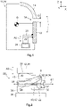
- a means of transporting people and/or goods 10 is shown on the basis of a basic representation, which has a first component 12 and a second component 14 .
- the means of transporting people and/or goods 10 should be designed as a vehicle 16, in particular as a motor vehicle, although the following embodiments essentially also apply to other embodiments of the means of transporting people and/or goods 10 such as trains, ships or airplanes apply equally.
- the first component 12 can be a bumper or a headlight, for example, whereas the second component 14 can be a hood, for example.
- the first component 12 and the second component 14 are arranged adjacent to form a joint 18 with the joint dimension G, the joint 18 being visible from the outside.
- the first component 12 is attached to the vehicle 16 so that it can rotate about an attachment point B, with an axially displaceable mounting also being conceivable.
- the first component 12 has a projection 20 which interacts with a device 22 according to the invention for adjusting the first component 12 relative to the second component 14 .
- the second component 14 should be located above the first component 12 in relation to the intended orientation of the vehicle 16 . Referring to figure 1 the device 22 is supported downwards on a carrier 24 of the vehicle 16 .
- the distance between the part of the first component 12 that forms the joint 18 and the fastening point B is selected such that actuation of the device 22 according to the invention mainly causes a movement of the first component 12 in the Z direction, as a result of which the joint dimension G of the joint 18 changes accordingly can be.
- the joint dimension G is usually less than 1 cm. Due to the fact that the second component 14 is arranged above the first component 12, the first component 12 must be moved against the force of gravity. Consequently, setting the gap dimension G is particularly difficult in this case.
- the device 22 according to the invention can equally be applied to the case in which the first component 12 and the second component 14 are arranged next to one another or in other orientations to one another.
- FIG 2 a first exemplary embodiment of the device 22 1 according to the invention is shown using a basic side view.
- the device 22 1 comprises a base body 26 which rests on the carrier 24 already mentioned, so that the device 22 1 can be supported on the carrier 24 .
- an extension arm 28 is fastened to the base body 26, to which an L-shaped adjusting body 30 is fastened so that it can rotate about a pivot point D, with the pivot point D also being able to be understood as an axis of rotation D.
- the cantilever 28 is designed as a separate component, although it can also be designed as an integral part of the base body 26, so that the base body 26 is in one piece.
- the device 22 1 rests at its upper end on the already described projection 20 of the first component 12 (see FIG figure 1 ).
- the device 22 1 according to the invention comprises an adjusting element 32 which is designed as a screw 34 which can be rotated about a first axis A1.
- the screw 34 is partially screwed into a threaded bore 36 arranged in the base body 26 .
- the screw 34 is pushed through a through hole 38 of the adjusting body 30 , the screw head 35 of the screw 34 resting against the adjusting body 30 .
- the adjusting body 30 has a first contact surface 37 for the screw head 35 of the screw 34 to act on, which is aligned essentially perpendicular to the first axis A1. Furthermore, the actuating body 30 has a second contact surface 39 for contacting the first component 12, which is aligned essentially perpendicular to the second axis A2.
- the adjusting body 30 has two legs 41, 43, which give the adjusting body 30 an approximately L-shaped design.
- the two legs 41, 43 are angled at approximately 90° to one another, with the pivot point D being arranged in the connection area of the two legs 41, 43 and with the first contact surface 37 being on one leg 41 and the second contact surface 39 being on the other leg 43 is trained.
- both the first contact surface 37 and the second contact surface 39 are convexly curved, which means that the respective contact surface 41, 43 is aligned essentially perpendicularly to the first axis A1 or second axis A2 even in different rotational positions about the pivot point D.
- the first contact surface 37 is arranged at a smaller distance from the pivot point D than the second contact surface 39.
- the device 22 1 has a fixing device 40 which causes the once set position of the adjustment element 32 and consequently of the adjusting body 30 to be fixed and not changed even under loads during operation of the vehicle 16 .
- the fixing device 40 comprises a self-locking thread 42 arranged on the screw 34, but it can be used alternatively or cumulatively include, for example, not shown spring washers or other screw locking elements.
- the procedure is as follows:
- the screw 34 is rotated with a suitable tool about the first axis A1.
- the screw 34 is screwed further into the threaded bore 36 or moved out of it, so that the screw 34 is moved along the first axis A1.
- the adjusting body 30 is caused to rotate.
- the pivot point D and the orientation of the adjusting body 30 are selected such that the rotary movement about the pivot point D in the area relevant here mainly has an axial movement of the adjusting body 30 along a second axis A2, which is perpendicular to the first axis A1.
- the second axis A2 coincides with the Z-direction.
- the rotation of the adjusting body 30 causes the first component 12 to move either towards the second component 14 or away from the second component 14 .
- the joint dimension G is reduced or increased. Consequently, it is possible to adjust the clearance G by turning the screw 34 as specified. Due to the fact that the screw 34 has the self-locking thread 42, it remains in a selected position without rotating in an uncontrolled manner, for example as a result of vibrations and loads that occur when the vehicle 16 is in operation. Once the joint dimension G has been set, it therefore does not change.
- FIG. 3A and 3B a second exemplary embodiment of the device 22 2 according to the invention is shown using a perspective illustration or a side view.
- the device 22 1 according to the invention according to the second exemplary embodiment essentially corresponds to the first exemplary embodiment, but in this case the cantilever 28 is designed in one piece with the base body 26 .
- a third exemplary embodiment of the device 22 3 according to the invention is shown using a side view.
- the basic structure of the device 22 1 according to the third exemplary embodiment is the same as that of the device 22 1 , 22 2 according to the first or second exemplary embodiment, however, the device 22 3 is mounted in the vehicle 16 rotated by 180°.
- the base body 26 is attached to the projection 20 of the first component 12 and is therefore not supported on the support 24 of the vehicle 16 .
- the adjusting body 30 is not in contact with the projection 20 of the first component 12, but rather with the support 24 of the vehicle 16.
- the setting of the gap dimension G takes place in the manner described above.
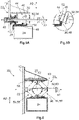
- FIG 5A a fourth exemplary embodiment of the device 22 4 according to the invention is shown using a side view.
- the adjusting body 30 is designed as a non-rotatable and axially non-displaceable eccentric body 44 fastened to the adjusting element 32, which is in turn designed as a screw 34 that can be rotated about the first axis A1.
- the eccentric body 44 has a helical bearing surface 46, the radius of which in relation to the first axis A1 and to the Figure 5A selected representation increases from left to right along the first axis A1.
- the base body 26 has a support section 48 with which the eccentric body 44 is in contact with the base body 26 with the support surface 46 .
- the screw 34 is screwed into an inserted into the first component 12 threaded sleeve 49, however, the pitch of the thread of the threaded sleeve 49 is the pitch of Bearing surface 46 of the eccentric body 44 adjusted so that in this embodiment, the thread of the threaded sleeve 49 can not be designed self-locking depending on the slope of the bearing surface 48. Consequently, depending on the design, the thread of the threaded sleeve 49 cannot assume the function of the fixing device 40 . In order nevertheless to prevent the screw 34 from rotating in an uncontrolled manner, the end of the eccentric body 44 pointing away from the threaded sleeve 49 rests against a friction section 50 which is formed by the base body 26 .
- the screw 34 is turned in one direction or the other about the first axis A1. As a result, the screw 34 is further moved into or out of the threaded sleeve 49 along the first axis A1. Due to the changing radius of the bearing surface 46, the first component 12 is thereby moved together with the screw 34 and the eccentric body 44 along the second axis A2 away from the base body 26 and the carrier 24 or towards the base body 26 and the carrier 24.
- the pitch of the thread of the threaded sleeve 49 is dimensioned in such a way that the bearing section 48 always remains on the bearing surface 46 of the eccentric body 44 .
- the eccentric body 44 has elevations 52 which delimit the bearing surface 46 towards its free end, as a result of which the bearing section 48 is guided on the bearing surface 46 .
- the friction section 50 of the base body 26 bears against the end of the eccentric body 44 pointing away from the threaded sleeve 49 . Due to the frictional force acting between the friction section 50 and the eccentric body 44, the screw 34 is prevented from being uncontrolled around the first Axis A1 rotates. Consequently, in this exemplary embodiment, the friction section 50 forms the fixing device 40.
- a fifth exemplary embodiment of the device 22 5 according to the invention is also shown in a side view.
- the adjusting body 30 comprises two pairs of scissors 54 , each of which has two scissor members 56 .
- the two lower scissor links 56 are rotatably connected to the base body 26 of the device 22 5 , which is on the in figure 1 shown carrier 24 of the vehicle 16 is supported.
- the two upper scissor links 56 are rotatably connected to a support body 58, which is also in figure 1 shown projection 20 of the first component 12 is fixed.
- the projection 20 can have fastening sections, not shown here, to which the two upper scissor elements 56 are fastened.
- the scissors members 56 of a pair of scissors 54 are rotatably connected to one another. All axes of rotation of the pairs of scissors 54 run parallel and in relation to the figure 6 selected representation perpendicular to the plane of the drawing.
- the adjusting element 32 comprises a spindle 60 which penetrates the two pairs of scissors 54 .
- a spindle nut 62 is screwed onto the spindle 60 and is non-rotatable with the in figure 6 left pair of scissors 54 connected.
- the spindle 60 is rotated in one direction or the other about the first axis A1.
- the spindle nut 62 is moved in one direction or the other axially along the first axis A1 and transmits this movement to the left pair of scissors 54. If the spindle 60 is moved so that the spindle nut 62 based on the figure 6 moved to the right, the angle enclosed by the two scissor elements 56 is increased, whereby the first component 12 is lifted along the second axis A2. As a result, the joint dimension G is reduced.
- the spindle 60 In order to prevent the spindle 60 itself from moving along the first axis A1, it has a diameter enlargement 63 which can be designed, for example, in the manner of a locking ring, with which the spindle 60 rests on the right-hand pair of scissors 54.
- a second spindle nut 62 (not shown here) can be provided, which moves in a direction toward or away from the first spindle nut 62 when the spindle 60 rotates.
- Such a movement can be achieved, for example, in that the spindle 60 has two thread sections, of which one thread section has a positive pitch and the other thread section has a negative pitch.
- the spindle 60 has a self-locking thread 42, which in this exemplary embodiment represents the fixing device 40 and prevents the spindle 60 from being able to rotate about its own axis A1 in an uncontrolled manner.
- FIG 7 a sixth exemplary embodiment of the device 22 6 according to the invention is shown using a side view.
- the device 22 1 according to the sixth exemplary embodiment has a spindle 60 and a spindle wedge 64 arranged on the spindle 60 .
- the spindle 60 forms the adjusting element 32 and the spindle wedge 64 forms the adjusting body 30.
- the spindle wedge 64 is designed in the manner of a spindle nut 62, but has an inclined surface 66. With this inclined surface 66, the spindle wedge 64 rests on a wedge section 68 of the base body 26, which is designed to correspond to the spindle wedge 64 and, in particular, has the same inclination.
- the spindle wedge 64 moves along the Axis of rotation of the spindle 60 or the first axis A1, whereby the first component 12 is moved together with the spindle 60 and the spindle wedge 64 along the second axis A2 towards the second component 14 or away from the second component 14, whereby the joint dimension G changes accordingly becomes.
- the projection 20 is formed in an L-shape. In relation to the first axis A1, the spindle 60 rests on the one hand against the free leg of the L-shaped projection 20 and on the other hand against the first component 12.
- a seventh exemplary embodiment of the device 22 7 according to the invention is shown in a side view.
- the seventh exemplary embodiment is largely the same as that in FIG figure 7 illustrated sixth embodiment, but the base body 26 is not on the carrier 24, but on the projection 20 of the first component 12 is arranged.
- the spindle wedge 64 which in Figure 8B shown separately by means of a perspective view, rests on the carrier 24 and with the inclined surface 66 on the wedge section 68 of the base body 26 .
- the spindle wedge 64 has no thread with which it interacts with the spindle 60 .
- the movement of the spindle key 64 along the first axis A1 is effected instead with the spindle nut 62 which is screwed onto the spindle 60 and which is connected to the spindle key 64 in a rotationally fixed manner. If the spindle 60 is rotated, the spindle wedge 64 is moved by means of the spindle nut 62 not only relative to the wedge section 68 of the base body 26, but also relative to the carrier 24 along the first axis A1. As in the sixth exemplary embodiment, the spindle 60 is attached to the first component 12 in such a way that it cannot move along the first axis A1.
- the base body 26 is L-shaped designed so that the spindle 60 is also secured on the free leg against displacement along the first axis A1.
- the spindle wedge 64 acts as the fixing device 40.
- a frictional force also acts between the spindle wedge 64 and the carrier 24, so that the position of the once adjusted Adjusting element 32 and the adjusting body 30, in this case the spindle wedge 64, is additionally fixed.
- the adjustment element 32 is designed as a gear wheel 70 which has an engagement section 74 designed as a hexagon 72 in the exemplary embodiment shown, into which a correspondingly shaped tool can be inserted.
- the gear 70 to the perpendicular to the plane of the Figure 9A running first axis A1 are rotated.
- the gear wheel 70 meshes with an intermediate gear wheel 76 which can be rotated about a further axis of rotation T running parallel to the first axis A1 of the first gear wheel 70 .
- the other gear 70 is in meshing engagement with a rack 78 which is axially movable perpendicular to the first axis A1 and the further axis of rotation T along the second axis A2.
- the toothed rack 78 is connected to the first component 12 (not shown here), so that a rotation of the gear wheel 70 about the first axis A1 causes the first component 12 to move toward the second component 14 in or away from the second component 14.
- gear wheel 70 is shown in an open position, in which the rotation of the gear wheel 70 about the first axis A1 is possible, in Figure 9C gear 70 is shown in a locked position in which rotation of gear 70 is locked.
- gear wheel 70 is mounted in the base body 26 so that it can move axially along the first axis A1. Both in the open position and in the locked position, the gear wheel 70 remains in meshing engagement with the intermediate gear wheel 76 .
- the base body 26 has a blocking section 80 which is designed to correspond to the gear wheel 70 .
- the gear wheel 70 engages in a form-fitting manner in the locking section 80, as a result of which the rotation of the gear wheel 70 about its own axis of rotation or about the first axis A1 is prevented.
- the first member 12 cannot be moved toward or away from the second member 14 along the second axis A2 when the gear 70 is in the locked position. Consequently, in this embodiment, the fixing device 40 is formed in the form of the locking portion 80 .
- a ninth exemplary embodiment of the device 22 9 according to the invention is shown on the basis of various views.
- the basic structure of the device 22 9 according to the ninth embodiment corresponds to the structure of the device 22 8 according to the eighth embodiment, but the gear 70 is designed as a bevel gear 82 in this case. Consequently, the first axis A1 and the further axis of rotation T do not run parallel to one another, but enclose an angle.
- the fixing device 40 is constructed somewhat differently. Due to the fact that the gear 70 is formed as a bevel gear 82, it cannot be moved axially along the first axis A1 without losing mesh with the intermediate gear 76.
- the fixing device 40 has a blocking element 84 which is axially displaceable on a bearing axis 86 connected to the bevel gear 82 in a torque-proof manner, but is connected to the bearing axis 86 in a torque-proof manner.
- the blocking element 84 is prestressed in a blocking position by means of a spring 88 .
- the blocking element 84 can be designed in the manner of a toothed wheel 70, but can also have a polygonal cross section.
- the locking element 84 engages in a form-fitting manner in a corresponding locking section 80 of the base body 26, so that the locking element 84 and consequently the gear wheel 70 cannot be rotated about the first axis A1.
- the first component 12 cannot be moved toward or away from the second component 14 along the second axis A2.
- the locking element 84 can be moved against the spring force applied by the spring 88 by means of a wrench 90 into the open position in which the gear 70 can be rotated and consequently the first component 12 can be moved towards or away from the second component 14.
- the wrench 90 only has to be pulled out of the gear wheel 70, whereby the gear wheel 70 is released from the spring 88 again is placed in the locked position. This fixes the joint dimension G once it has been set.
Description
Die vorliegende Erfindung betrifft eine Vorrichtung zum Verstellen eines ersten Bauteils und eines zweiten Bauteils eines Personen- und/oder Gütertransportmittels relativ zueinander. Weiterhin betrifft die Erfindung ein Personen- und/oder Gütertransportmittel mit einer derartigen Vorrichtung.The present invention relates to a device for adjusting a first component and a second component of a means of passenger and/or goods transport relative to one another. Furthermore, the invention relates to a means of transporting people and/or goods with such a device.
Das Personen- und/oder Gütertransportmittel ist insbesondere als Fahrzeug ausgeführt, kann aber auch ein Schiff, ein Flugzeug, ein Zug oder dergleichen sein. Wenn im Folgenden die Erfindung in Bezug auf Fahrzeuge erläutert wird, gelten die Ausführungen gleichermaßen auch für andere Personen- und/oder Gütertransportmittel wie Schiffe, Flugzeuge, Züge oder dergleichen.The means of transporting people and/or goods is designed in particular as a vehicle, but can also be a ship, an airplane, a train or the like. If the invention is explained below in relation to vehicles, the statements also apply equally to other means of transporting people and/or goods such as ships, airplanes, trains or the like.
Die insbesondere bei Fahrzeugen als Verkaufsargument wichtige Qualitätsanmutung wird unter anderem von einem gleichmäßigen und geringen Maß der sichtbaren Fugen geprägt, mit dem zwei benachbarte Bauteile, bei Fahrzeugen beispielsweise die Motorhaube, der Scheinwerfer und der Stoßfänger, benachbart zueinander angeordnet sind. Aufgrund von Schwankungen in der Fertigung sind die Bauteile jedoch nie exakt gleich groß, so dass sich bei jedem Fahrzeug ein anderes Fugenmaß einstellt. Um dennoch ein gleichmäßiges Fugenmaß zu erhalten, wird das Fugenmaß bei jedem Fahrzeug gesondert auf folgende Weise vorgegangen: Zumindest eines der beiden benachbart angeordneten Bauteile ist in einem gewissen Umfang beweglich am Fahrzeug montiert. Die Bewegung wird üblicherweise mittels einer Exzenterscheibe erzeugt, die zwischen dem bewegbaren Bauteil und einem Träger, auf den das bewegliche Bauteil abgestützt ist, drehbar angeordnet ist. Durch Drehen der Exzenterscheibe kann das betreffende Bauteil zum benachbart angeordneten Bauteil hin oder von diesem weg bewegt werden. Hierdurch kann das Fugenmaß eingestellt werden.The perceived quality, which is particularly important as a sales argument for vehicles, is characterized, among other things, by an even and small dimension of the visible joints with which two adjacent components, for example the bonnet, headlights and bumper of vehicles, are arranged adjacent to one another. Due to fluctuations in production, however, the components are never exactly the same size, so that the gap dimensions are different for each vehicle. In order to nevertheless obtain a uniform joint dimension, the joint dimension is proceeded separately for each vehicle in the following way: At least one of the two adjacently arranged components is mounted on the vehicle so that it can move to a certain extent. The movement is usually generated by means of an eccentric disk between the movable component and a bracket on which the movable member is supported. By rotating the eccentric disc, the component in question can be moved towards or away from the component arranged adjacent to it. This allows the joint size to be adjusted.
Um mittels der Exzenterscheibe das betreffende Bauteil zum benachbart angeordneten Bauteil hin zu bewegen oder von diesem weg zu bewegen, ist üblicherweise ein vergleichsweise hoher Kraftaufwand notwendig, der vom betreffenden Mitarbeiter des Fahrzeugherstellers aufgebracht werden muss. Üblicherweise weist die Exzenterscheibe eine Aufnahme für einen Schraubenschlüssel auf, mit welchem der Mitarbeiter die hierzu notwendige Kraft aufbringen kann. Da jedoch der Kraftaufwand vergleichsweise hoch ist, das Fugenmaß aber sehr genau eingestellt werden muss, kann es einen erheblichen Zeitaufwand bedeuten, dass Fugenmaß wie vorgegeben einzustellen. Weiterhin ist die Wirksamkeit der Exzenterscheibe gering. Darüber hinaus neigt die Exzenterscheibe dazu, sich infolge der im Betrieb des Fahrzeugs auftretenden Vibrationen zu verstellen, wodurch sich auch das eingestellte Fugenmaß ändert.In order to use the eccentric disc to move the relevant component towards or away from the adjacent component, a comparatively large amount of force is usually required, which must be applied by the relevant employee of the vehicle manufacturer. The eccentric disk usually has a socket for a wrench, with which the employee can apply the necessary force. However, since the effort required is comparatively high, but the joint dimension has to be set very precisely, it can take a considerable amount of time to set the joint dimension as specified. Furthermore, the effectiveness of the eccentric disc is low. In addition, the eccentric disk tends to move as a result of the vibrations that occur during operation of the vehicle, which also changes the set gap dimension.
Die
Weitere derartige Vorrichtungen sind in der
Aufgabe einer Ausführungsform der vorliegenden Erfindung ist es, eine Vorrichtung anzugeben, mit welcher es mit einfachen und kostengünstigen Mitteln möglich ist, das Fugenmaß eines ersten Bauteils und eines zweiten Bauteils eines Personenund/oder Gütertransportmittels in kurzer Zeit wie vorgegeben einzustellen, wobei das einmal eingestellte Fugenmaß auch unter den im Betrieb auftretenden Vibrationen aufrecht erhalten werden soll. Des Weiteren liegt einer Ausgestaltung der vorliegenden Erfindung die Aufgabe zugrunde, ein Personenund/oder Gütertransportmittel mit einer derartigen Vorrichtung bereitzustellen.The object of one embodiment of the present invention is to provide a device with which it is possible to set the joint dimension of a first component and a second component of a means of passenger and/or goods transport in a short time using simple and inexpensive means, with the joint dimension once set should also be maintained under the vibrations that occur during operation. Furthermore, an embodiment of the present invention is based on the object of providing a means of transporting people and/or goods with such a device.
Diese Aufgabe wird mit den in den Ansprüchen 1, 6, 9, 10 und 15 angegebenen Merkmalen gelöst. Vorteilhafte Ausführungsformen sind Gegenstand der Unteransprüche.This object is achieved with the features specified in claims 1, 6, 9, 10 and 15. Advantageous embodiments are the subject matter of the dependent claims.
Eine Ausführungsform der Erfindung betrifft eine Vorrichtung zum Verstellen eines ersten Bauteils und eines zweiten Bauteils eines Personen- und/oder Gütertransportmittels relativ zueinander, wobei die beiden Bauteile unter Ausbildung einer Fuge benachbart zueinander angeordnet sind, umfassend einen Grundkörper, ein entlang einer ersten Achse und/oder um die erste Achse bewegbar im Grundkörper gelagertes Verstellelement, einen entlang einer zweiten Achse bewegbar im Grundkörper gelagerten Stellkörper, der derart mit dem Verstellelement zusammenwirkt, dass die Bewegung des Verstellelements entlang der ersten Achse oder um die erste Achse in einen Bewegung des Stellkörpers und/oder des Verstellelements entlang der zweiten Achse umgewandelt wird, wobei die Bewegung des Stellkörpers und/oder des Verstellelements entlang der zweiten Achse auf das erste Bauteil oder das zweite Bauteil übertragbar ist, und eine Fixiereinrichtung zum Fixieren des Verstellelements und des Stellkörpers in einer wählbaren Position.One embodiment of the invention relates to a device for adjusting a first component and a second component of a means of passenger and/or goods transport relative to one another, the two components being arranged adjacent to one another to form a joint, comprising a base body, a along a first axis and/or or adjustment element mounted in the base body so that it can move about the first axis, an adjusting body mounted in the base body so that it can move along a second axis, which interacts with the adjusting element in such a way that the movement of the adjusting element along the first axis or about the first axis results in a movement of the adjusting body and/or or the adjustment element is converted along the second axis, the movement of the adjustment body and/or the adjustment element along the second axis being transferrable to the first component or the second component, and a fixing device for fixing the adjustment element and the adjustment body in one selectable position.
Unter einem Verstellelement soll ein Element verstanden werden, welches von einer Person, beispielsweise von einem Mitarbeiter des Herstellers des Personen- und/oder Gütertransportmittels oder einer Reparaturwerkstatt, vorzugsweise mittels eines geeigneten Werkzeugs betätigt werden kann. Der Stellkörper wandelt die Bewegung des Verstellelements entlang der ersten Achse und/oder um die erste Achse in eine Bewegung entlang der zweiten Achse um.An adjustment element is to be understood as an element which can be actuated by a person, for example by an employee of the manufacturer of the means of passenger and/or goods transport or a repair shop, preferably using a suitable tool. The adjusting body converts the movement of the adjustment element along the first axis and/or around the first axis into a movement along the second axis.
Vorschlagsgemäß wirken in der Vorrichtung zwei Einheiten zusammen, nämlich das Verstellelement und der Stellkörper. Das Zusammenwirken kann derart gestaltet werden, dass eine Übersetzung bei der Umwandlung der Bewegung des Verstellelements in die Bewegung des Stellkörpers bewirkt wird. Hierdurch ist es möglich, den zum Verstellen des ersten Bauteils und des zweiten Bauteils relativ zueinander benötigten Kraftaufwand gering zu halten. Darüber hinaus weist die vorschlagsgemäße Vorrichtung die Fixiereinrichtung auf, mit welcher die Position des Stellelements und des Stellkörpers in einer wählbaren Position fixierbar ist. Hieraus folgt, dass sich auch die beiden relativ zueinander bewegbar Bauteile nicht mehr relativ zueinander bewegen können, sobald die Position des Verstellelements und des Stellkörpers fixiert worden ist. Wie eingangs erwähnt, kann sich das Fugenmaß bei bekannten Personenund/oder Gütertransportmitteln infolge von im Betrieb auftretenden Belastungen und Vibrationen verstellen. Eine derartige Verstellung im Betrieb des Personen- und/oder Gütertransportmittels wird mittels der Fixiereinrichtung verhindert. Folglich bleibt das einmal eingestellte Fugenmaß erhalten. Der eingangs erwähnte Qualitätseindruck des betreffenden Personenund/oder Gütertransportmittels verschlechtert sich damit im Betrieb bezüglich des Fugenmaßes nicht.According to the proposal, two units work together in the device, namely the adjusting element and the adjusting body. The interaction can be designed in such a way that a translation is effected when converting the movement of the adjusting element into the movement of the actuating body. This makes it possible to keep the effort required to adjust the first component and the second component relative to one another low. In addition, the proposed device has the fixing device with which the position of the adjusting element and the adjusting body can be fixed in a selectable position. It follows from this that the two components that can be moved relative to one another can no longer move relative to one another as soon as the position of the adjusting element and the adjusting body has been fixed. As mentioned at the outset, the dimensions of the joints in known means of transporting people and/or goods can change as a result of loads and vibrations occurring during operation. Such an adjustment during operation of the means of passenger and/or goods transport is prevented by the fixing device. As a result, the joint dimension that has been set is retained. The initially mentioned quality impression of the relevant means of passenger and/or goods transport does not deteriorate during operation with regard to the gap dimension.
Erfindungsgemäß ist das Verstellelement als eine Schraube mit einem Schraubenkopf ausgebildet. Schrauben sind ein vielfach verwendetes Mittel, um eine Drehbewegung in eine Längsbewegung umzuwandeln. Sie sind kostengünstig beziehbar und einfach zu bedienen. Um zu verhindern, dass sich die Schraube unter den im Betrieb auftretenden Belastungen und Vibrationen löst und eine unkontrollierte Drehung durchführt, kann die Schraube beispielsweise mit Federscheiben oder anderen Schraubensicherungselementen gesichert werden, die in diesem Fall als Fixiereinrichtung wirken.According to the invention, the adjusting element is designed as a screw with a screw head. Screws are a widely used means of converting rotary motion into linear motion. They are inexpensive to obtain and easy to use. In order to prevent the screw from loosening under the loads and vibrations occurring during operation and from performing an uncontrolled rotation, the screw can be secured, for example, with spring washers or other screw locking elements, which in this case act as a fixing device.
Erfindungsgemäß ist die Fixiereinrichtung als ein selbsthemmendes Gewinde der Schraube ausgebildet. Die üblicherweise bei Schrauben verwendeten Gewinde sind ohnehin selbsthemmend, wobei dies nicht ausschließt, dass sich die betreffenden Schrauben im Betrieb unkontrolliert drehen können. In dieser Ausführungsform kann das Gewinde in einem besonderen Umfang selbsthemmend ausgeführt werden, beispielsweise dadurch, dass die Steigung des Gewindes besonders gering ist. In diesem Fall wirkt die Schraube nicht nur als das Verstellelement, sondern gleichzeitig auch als die Fixiereinrichtung, so dass die Vorrichtung nach diesem Ausführungsbeispiel mit besonders wenigen Bauelementen auskommt und daher eine geringe Komplexität aufweist.According to the invention, the fixing device is designed as a self-locking thread of the screw. The threads usually used in screws are self-locking anyway, although this does not rule out the possibility that the screws in question can turn uncontrollably during operation. In this embodiment, the thread can be designed to be self-locking to a particular extent, for example in that the pitch of the thread is particularly small. In this case, the screw acts not only as the adjusting element, but also as the fixing device, so that the device according to this exemplary embodiment makes do with particularly few components and is therefore of low complexity.
Nach einer weiteren Ausführungsform ist der Stellkörper insbesondere über einen Ausleger um einen Drehpunkt drehbar im Grundkörper gelagert, insbesondere um einen senkrecht zur ersten Achse und zur zweiten Achse gerichtete Drehpunkt. Der Stellkörper weist eine erste Kontaktfläche zur Beaufschlagung durch den Schraubenkopf der Schraube, die im Wesentlichen senkrecht zur ersten Achse ausgerichtet ist, und eine zweite Kontaktfläche zur Kontaktierung des ersten Bauteils oder des zweiten Bauteils auf, die im Wesentlichen senkrecht zur zweiten Achse ausgerichtet ist. Hierdurch wird auf einfache Art und Weise eine Richtungsumlenkung der Verstellbewegung erreicht. Hierzu weist der Grundkörper insbesondere ein zur Schraube passendes Innengewinde auf, welches in Richtung der ersten Achse ausgerichtet ist. Insbesondere weist der Stellkörper eine Öffnung zur Durchführung der Schraube auf, und die erste Kontaktfläche ist durch die die Öffnung umgebende Fläche gebildet.According to a further embodiment, the actuating body is mounted in the base body so as to be rotatable about a pivot point, in particular about a pivot point directed perpendicularly to the first axis and to the second axis, in particular via an extension arm. The adjusting body has a first contact surface for being acted upon by the screw head of the screw, which is oriented substantially perpendicularly to the first axis, and a second Contact surface for contacting the first component or the second component, which is aligned substantially perpendicular to the second axis. In this way, a direction deflection of the adjustment movement is achieved in a simple manner. For this purpose, the base body has, in particular, an internal thread that fits the screw and is aligned in the direction of the first axis. In particular, the adjusting body has an opening for the screw to pass through, and the first contact surface is formed by the surface surrounding the opening.
Nach Maßgabe einer weiteren Ausführungsform weist der Stellkörper zumindest zwei, insbesondere einen in etwa L-förmigen Stellkörper bildende, Schenkel auf, die zueinander im Bereich von 45° bis 135°, insbesondere in etwa 90° abgewinkelt sind, wobei der Drehpunkt im Verbindungspunkt der beiden Schenkel angeordnet ist und wobei die erste Kontaktfläche an dem einen Schenkel und die zweite Kontaktfläche an dem anderen Schenkel ausgebildet ist. Hierdurch wird auf einfach Art und Weise ein entsprechender Stellkörper realisiert.According to a further embodiment, the adjusting body has at least two legs, in particular forming an approximately L-shaped adjusting body, which are angled to one another in the range of 45° to 135°, in particular approximately 90°, with the pivot point at the connection point of the two Leg is arranged and wherein the first contact surface is formed on the one leg and the second contact surface on the other leg. As a result, a corresponding adjusting body is realized in a simple manner.
Eine fortgebildete Ausführungsform zeichnet sich dadurch aus, dass mindestens eine, bevorzugt beide der ersten und zweiten Kontaktflächen konvex gewölbt sind, womit bewirkt wird, dass auch in verschiedenen Drehpositionen um den Drehpunkt die jeweilige Kontaktfläche im Wesentlichen senkrecht zur ersten Achse oder zweiten Achse ausgerichtet ist. Hierdurch wird der Kontakt zu dem Bauteil bzw. zur Schraube verbessert.A further developed embodiment is characterized in that at least one, preferably both, of the first and second contact surfaces are convexly curved, which causes the respective contact surface to be aligned essentially perpendicular to the first axis or second axis even in different rotational positions around the pivot point. This improves the contact with the component or the screw.
Nach einer weitergebildeten Ausführungsform ist die erste Kontaktfläche in einem anderen, insbesondere geringerem, Abstand zum Drehpunkt angeordnet als die zweite Kontaktfläche. Hierdurch kann eine vorteilhafte Übersetzung durch Festlegung der unter-schiedlichen Abstände bestimmt werden.According to a further developed embodiment, the first contact surface is arranged at a different, in particular smaller, distance from the pivot point than the second contact surface. Through this an advantageous translation can be determined by defining the different distances.
Bei einer erfindungsgemäßen Ausbildung der Vorrichtung kann das Verstellelement als eine Schraube ausgebildet sein, wobei der Stellkörper als ein auf der Schraube insbesondere ortsfest angeordneter Exzenterkörper ausgebildet ist. Der Exzenterkörper ermöglicht es, den Stellkörper raumsparend und einfach auszugestalten. Hierdurch kann die gesamte Vorrichtung kompakt gestaltet werden und auch dort angeordnet werden, wo der zur Verfügung stehende Bauraum begrenzt ist.In an embodiment of the device according to the invention, the adjusting element can be designed as a screw, with the adjusting body being designed as an eccentric body arranged in particular in a stationary manner on the screw. The eccentric body makes it possible to design the adjusting body in a space-saving and simple manner. As a result, the entire device can be made compact and can also be arranged where the available space is limited.
Bei einer weiteren Ausführungsform kann der Exzenterkörper eine wendelförmige Auflagefläche mit einem sich in Bezug auf die erste Achse ändernden Radius aufweisen, wobei sich der Exzenterkörper auf einem Auflageabschnitt des Grundkörpers abstützt. In dieser Ausführungsform wird eine besonders gute Führung des Exzenterkörpers in Bezug auf den Grundkörper bereitgestellt, wodurch die beiden relativ zueinander zu verstellenden Bauteile ebenfalls sehr präzise bewegt werden können. Das Fugenmaß kann folglich sehr genau eingestellt werden.In a further embodiment, the eccentric body can have a helical bearing surface with a radius that changes in relation to the first axis, with the eccentric body being supported on a bearing section of the base body. In this embodiment, the eccentric body is guided particularly well in relation to the base body, as a result of which the two components that are to be adjusted relative to one another can likewise be moved very precisely. The joint dimension can therefore be set very precisely.
Eine weitergebildete Ausführungsform zeichnet sich dadurch aus, dass die Fixiereinrichtung einen am Grundkörper angeordneten und mit dem Exzenterkörper zusammenwirkenden Reibabschnitt umfasst. In dieser Ausführungsform kann die Fixiereinrichtung besonders einfach ausgebildet sein, nämlich dadurch, dass der Exzenterkörper gegen den Reibabschnitt des Grundkörpers gedrückt wird. Folglich muss eine Reibkraft überwunden werden, welche verhindert, dass sich die Schraube im Betrieb des Personen- und/oder Gütertransportmittels unkontrolliert dreht und sich das eingestellte Fugenmaß ändert.A further developed embodiment is characterized in that the fixing device comprises a friction section which is arranged on the base body and interacts with the eccentric body. In this embodiment, the fixing device can be designed in a particularly simple manner, namely in that the eccentric body is pressed against the friction section of the base body. Consequently, a frictional force must be overcome, which prevents the screw from turning uncontrolled during operation of the passenger and/or goods transport means and the set joint dimension from changing.
Eine Ausbildung der Erfindung ist dadurch gekennzeichnet, dass das Verstellelement eine Spindel und der Stellkörper eine auf der Spindel angeordnete Spindelmutter und ein Scherenpaar mit zwei Scherengliedern umfasst, wobei die Spindelmutter drehfest mit dem Scherenpaar befestigt ist, wobei das erste der Scherenglieder drehbar am Grundkörper und das andere der Scherenglieder drehfest mit einem Auflagekörper befestigt ist, auf welchem das erste Bauteil oder das zweite Bauteil auflegbar ist, oder das erste der Scherenglieder drehbar am Grundkörper befestigt und das andere der Scherenglieder drehfest am ersten Bauteil oder dem zweiten Bauteil befestigbar ist. Die Verwendung des Scherenpaares ermöglicht es, das betreffende Bauteil sehr präzise relativ zum zweiten Bauteil zu bewegen. Das Fugenmaß lässt sich daher sehr genau einstellen. Darüber hinaus ist es mittels des Scherenpaares möglich, große Übersetzungsverhältnisse zu realisieren, so dass auch schwere Bauteile ohne einen unvertretbar großen Kraftaufwand für den die Bauteile montierenden Mitarbeiter relativ zueinander bewegt werden können, um das gewünschte Fugenmaß einzustellen.One embodiment of the invention is characterized in that the adjusting element comprises a spindle and the adjusting body comprises a spindle nut arranged on the spindle and a pair of scissors with two scissor links, the spindle nut being fixed in a rotationally fixed manner to the pair of scissors, the first of the scissor links being rotatable on the base body and the the other of the scissor members is non-rotatably attached to a support body on which the first component or the second component can be placed, or the first of the scissor members is rotatably attached to the base body and the other of the scissor members is non-rotatably attached to the first component or the second component. The use of the pair of scissors makes it possible to move the component in question very precisely relative to the second component. The joint dimension can therefore be set very precisely. In addition, it is possible by means of the pair of scissors to realize large transmission ratios, so that even heavy components can be moved relative to one another without an unacceptably large amount of effort for the employee assembling the components in order to set the desired joint dimension.
Eine weitere Ausführungsform zeichnet sich dadurch aus, dass das Verstellelement eine Spindel und der Stellkörper einen auf der Spindel oder um die Spindel angeordneten Spindelkeil umfasst, und der Grundkörper einen zum Spindelkeil korrespondierenden Keilabschnitt aufweist, wobei sich der Spindelkeil auf dem Keilabschnitt abstützt oder umgekehrt. Der Spindelkeil und der Keilabschnitt weisen jeweils eine sehr einfache geometrische Form auf, so dass sich diese Ausführungsform durch eine einfache Formgebung auszeichnet. Darüber hinaus wirken der Spindelkeil und der korrespondierenden Keilabschnitt als die Fixiereinrichtung, da zwischen ihnen eine besonders hohe Reibkraft wirkt, welche ein Verstellen des Fugenmaßes im Betrieb verhindert.A further embodiment is characterized in that the adjusting element comprises a spindle and the adjusting body comprises a spindle wedge arranged on the spindle or around the spindle, and the base body has a wedge section corresponding to the spindle wedge, with the spindle wedge being supported on the wedge section or vice versa. The spindle wedge and the wedge section each have a very simple geometric shape, so that this embodiment is characterized by a simple shape. In addition, the spindle wedge and the corresponding wedge section act as the fixing device, since a particularly high frictional force acts between them, which prevents the joint dimension from being adjusted during operation.
Eine fortgebildete Ausführungsform gibt vor, dass die Fixiereinrichtung ein mit dem Verstellelement drehfest und axial auf dem Verstellelement verschiebbares Sperrelement aufweist, wobei das Sperrelement zwischen einer Sperrstellung, in welcher das Sperrelement die Drehung des Verstellelements um die erste Achse sperrt, und einer Offenstellung, in welcher das Sperrelement die Drehung des Verstellelements ermöglicht, axial verschiebbar ist. In dieser Ausführungsform muss der Mitarbeiter beim Einstellen des Fugenmaßes das Sperrelement aus der Sperrstellung zunächst in die Offenstellung bewegen, bevor er die beiden betreffenden Bauteile relativ zueinander bewegen und das Fugenmaß einstellen kann. Ist das vorgesehene Fugenmaß erreicht, stellt der Mitarbeiter das Sperrelement zurück in die Sperrstellung, in welcher eine Drehung des Verstellelements verhindert wird. Infolgedessen wird darüber hinaus verhindert, dass sich die beiden betreffenden Bauteile im Betrieb relativ zueinander verstellen können und sich das Fugenmaß ändert.A further developed embodiment specifies that the fixing device has a locking element that is non-rotatable with the adjustment element and can be moved axially on the adjustment element, with the locking element between a locked position, in which the locking element blocks the rotation of the adjustment element about the first axis, and an open position, in which the locking element allows the rotation of the adjusting element, is axially displaceable. In this embodiment, when setting the joint dimension, the employee must first move the blocking element from the blocked position into the open position before he can move the two relevant components relative to one another and set the joint dimension. Once the intended joint dimension has been reached, the employee resets the blocking element to the blocking position, in which rotation of the adjustment element is prevented. As a result, it is also prevented that the two relevant components can be adjusted relative to each other during operation and the joint dimension changes.
Gemäß einer weiteren Ausführungsform ist das Verstellelement als ein drehbar im Grundkörper gelagertes Zahnrad ausgebildet, welches mit dem als eine entlang der zweiten Achse beweglichen Zahnstange ausgebildeten Stellkörper in kämmenden Eingriff steht. Mithilfe des Zahnrads und der mit dem Zahnrad in kämmenden Eingriff stehenden Zahnstange können große Übersetzungsverhältnisse auf engem Raum bereitgestellt werden, so dass auch schwerere Bauteile auf das vorgesehene Fugenmaß gebracht werden können, ohne dass ein unvertretbar hoher Kraftaufwand von dem diese Bauteile montierenden Mitarbeiter aufgebracht werden muss.According to a further embodiment, the adjusting element is designed as a gear wheel which is rotatably mounted in the base body and which is in meshing engagement with the adjusting body designed as a rack movable along the second axis. With the help of the gear wheel and the toothed rack that meshes with the gear wheel, large transmission ratios can be provided in a small space, so that even heavier components can be brought to the intended joint dimension without the employee assembling these components having to exert an unacceptably high amount of effort .
Nach einer Variante der Erfindung ist zwischen dem Zahnrad und der Zahnstange ein drehbar im Grundkörper gelagertes Zwischenzahnrad angeordnet. Auch das Zwischenzahnrad dient dazu, die Übersetzungsverhältnisse zu erhöhen und dadurch das Einstellen des Fugenmaßes für den Mitarbeiter besonders einfach zu machen.According to a variant of the invention, an intermediate gear rotatably mounted in the base body is arranged between the gear wheel and the toothed rack. The intermediate gear wheel also serves to increase the transmission ratios and thus make it particularly easy for the employee to set the joint dimension.
Zudem kann in einer weiteren Ausführungsform vorgesehen sein, dass das Zahnrad als ein Kegelrad ausgebildet ist. Mithilfe des Kegelrades kann die Zugänglichkeit des Verstellelements entsprechend den Anforderungen der Fertigung gewählt werden. Darüber hinaus ist es auch möglich, die vorschlagsgemäße Vorrichtung an schwer zugänglichen Stellen einzusetzen, so dass auch Bauteile auf das gewünschte Fugenmaß gebracht werden können, deren Fugenmaß bislang noch nicht einstellbar war. Hierdurch lässt sich der Qualitätseindruck des betreffenden Personen- und/oder Gütertransportmittels weiter steigern.In addition, it can be provided in a further embodiment that the gear wheel is designed as a bevel gear. With the help of the bevel gear, the accessibility of the adjustment element can be selected according to the requirements of the production. In addition, it is also possible to use the proposed device in places that are difficult to access, so that components whose joint dimensions have not yet been adjustable can also be brought to the desired joint dimension. As a result, the quality impression of the passenger and/or goods transport in question can be further increased.
Eine weiterführende Ausführungsform zeichnet sich dadurch aus, dass das Zahnrad axial verschiebbar im Grundkörper gelagert ist, wobei das Zahnrad zwischen einer Sperrstellung, in welcher die Drehung des Verstellelements um die erste Achse gesperrt ist, und einer Offenstellung, in welcher die Drehung des Verstellelements möglich ist, axial verschiebbar ist. In dieser Ausführungsform muss der Mitarbeiter beim Einstellen des Fugenmaßes das Zahnrad aus der Sperrstellung zunächst in die Offenstellung bewegen, bevor er die beiden betreffenden Bauteile relativ zueinander bewegen und das Fugenmaß einstellen kann. Ist das vorgesehene Fugenmaß erreicht, stellt der Mitarbeiter das Zahnrad zurück in die Sperrstellung, in welcher eine Drehung des Verstellelements verhindert wird. Infolgedessen wird darüber hinaus verhindert, dass sich die beiden betreffenden Bauteile im Betrieb relativ zueinander verstellen können und sich das Fugenmaß ändert.A further embodiment is characterized in that the gear wheel is mounted in the base body in an axially displaceable manner, the gear wheel between a blocked position, in which the rotation of the adjustment element about the first axis is blocked, and an open position, in which the rotation of the adjustment element is possible , is axially displaceable. In this embodiment, when setting the gap dimension, the employee must first move the gearwheel from the locked position to the open position before he can move the two relevant components relative to one another and adjust the gap dimension. Once the intended joint dimension has been reached, the employee puts the gear wheel back into the locked position, in which the adjustment element is prevented from rotating. As a result, the two are also prevented from each other affected components can be adjusted relative to each other during operation and the joint dimension changes.
Gemäß einer weiteren Ausführungsform weist der Grundkörper einen zum Zahnrad korrespondierenden Sperrabschnitt auf, in welchen das Zahnrad in der Sperrstellung formschlüssig eingreift. Der Sperrabschnitt lässt sich in dieser Ausführungsform besonders einfach fertigen.According to a further embodiment, the base body has a locking section which corresponds to the gear wheel and in which the gear wheel engages in a form-fitting manner in the locked position. In this embodiment, the blocking section can be manufactured particularly easily.
Eine Ausbildung der Erfindung betrifft ein Personen- und/oder Gütertransportmittel, umfassend ein erstes Bauteil und ein zweites Bauteil, wobei die beiden Bauteile unter Ausbildung einer Fuge benachbart zueinander angeordnet sind, und eine Vorrichtung nach einem der zuvor erläuterten Ausführungsformen, wobei das erste Bauteil und das zweite Bauteil mittels der Vorrichtung relativ zueinander verstellbar sind, wodurch das Fugenmaß der Fuge veränderbar ist.One embodiment of the invention relates to a means of transporting people and/or goods, comprising a first component and a second component, the two components being arranged adjacent to one another to form a joint, and a device according to one of the previously explained embodiments, the first component and the second component can be adjusted relative to one another by means of the device, as a result of which the joint dimensions of the joint can be changed.
Die technischen Effekte und Vorteile, die sich mit dem vorschlagsgemäßen Personen- und/oder Gütertransportmittel erreichen lassen, entsprechen denjenigen, die für die vorliegende Vorrichtung zum Verstellen eines ersten Bauteils und eines zweiten Bauteils erörtert worden sind. Zusammenfassend sei darauf hingewiesen, dass sich einerseits das Fugenmaß mit einem geringen Kraftaufwand wie vorgegeben einstellen lässt, auch wenn das zu bewegende Bauteil relativ schwer ist. Andererseits wird mittels der Fixiereinrichtung verhindert, dass sich das einmal eingestellte Fugenmaß infolge der im Betrieb des Personen- und/oder Gütertransportmittels auftretenden Vibrationen und Belastungen unkontrolliert ändert.The technical effects and advantages that can be achieved with the proposed passenger and/or goods transport means correspond to those that have been discussed for the present device for adjusting a first component and a second component. In summary, it should be pointed out that, on the one hand, the joint dimension can be set as specified with little effort, even if the component to be moved is relatively heavy. On the other hand, the fixing device prevents the joint dimension, once set, from changing in an uncontrolled manner as a result of the vibrations and loads occurring during operation of the passenger and/or goods transport means.
Beispielhafte Ausführungsformen der Erfindung werden im Folgenden unter Bezugnahme auf die beigefügten Zeichnungen näher erläutert. Es zeigen
- Figur 1
- eine prinzipielle Schnittdarstellung eines ersten Bauteils und eines zweiten Bauteils eines Personen- und/oder Gütertransportmittels und einer erfindungsgemäßen Vorrichtung, mit welcher die Bauteile relativ zueinander verstellbar sind,
- Figur 2
- eine prinzipielle Darstellung eines ersten Ausführungsbeispiels einer erfindungsgemäßen Vorrichtung,
- Figuren 3A und 3B
- ein zweites Ausführungsbeispiel eines zweiten Ausführungsbeispiels der erfindungsgemäßen Vorrichtung anhand einer perspektivischen Darstellung bzw. anhand einer Seitenansicht,
- Figur 4
- ein drittes Ausführungsbeispiel der erfindungsgemäßen Vorrichtung anhand einer Seitenansicht,
- Figur 5A
- ein viertes Ausführungsbeispiel der erfindungsgemäßen Vorrichtung anhand einer Seitenansicht,
- Figur 5B
- ein vergrößerter Ausschnitt des in
Figur 5A gezeigten vierten Ausführungsbeispiels, - Figur 6
- ein fünftes Ausführungsbeispiel der erfindungsgemäßen Vorrichtung anhand einer Seitenansicht,
- Figur 7
- ein sechstes Ausführungsbeispiel der erfindungsgemäßen Vorrichtung anhand einer Seitenansicht,
- Figur 8A
- ein siebtes Ausführungsbeispiel der erfindungsgemäßen Vorrichtung anhand einer Seitenansicht,
- Figur 8B
- eine perspektivische isolierte Darstellung des Spindelteils der Vorrichtung nach
Figur 8A , - Figur 9A
- eine prinzipielle Seitenansicht eines achten Ausführungsbeispiels der erfindungsgemäßen Vorrichtung,
- Figur 9B
- eine prinzipielle Schnittdarstellung des in
Figur 9A dargestellten achten Ausführungsbeispiels entlang der inFigur 9A definierten Schnittebene A-A, wobei sich die erfindungsgemäße Vorrichtung in einer Offenstellung befindet, - Figur 9C
- das in
Figur 9A dargestellte achte Ausführungsbeispiel ebenfalls entlang der inFigur 9 an definierten Schnittebene A-A, wobei sich die erfindungsgemäße Vorrichtung in einer Sperrstellung befindet, - Figur 10A
- ein neuntes Ausführungsbeispiel der erfindungsgemäßen Vorrichtung anhand einer perspektivischen Darstellung,
- Figur 10B
- eine Teilschnittdarstellung des in
Figur 10A dargestellten neunten Ausführungsbeispiels, wobei sich die erfindungsgemäße Vorrichtung in einer Sperrstellung befindet, und - Figur 10C
- eine Teilschnittdarstellung des neunten Ausführungsbeispiels, wobei sich die erfindungsgemäße Vorrichtung in einer Offenstellung befindet.
- figure 1
- a basic sectional view of a first component and a second component of a means of passenger and/or goods transport and a device according to the invention, with which the components can be adjusted relative to one another,
- figure 2
- a basic representation of a first embodiment of a device according to the invention,
- Figures 3A and 3B
- a second embodiment of a second embodiment of the device according to the invention based on a perspective view or based on a side view,
- figure 4
- a third embodiment of the device according to the invention based on a side view,
- Figure 5A
- a fourth embodiment of the device according to the invention based on a side view,
- Figure 5B
- an enlarged section of the in
Figure 5A shown fourth embodiment, - figure 6
- a fifth embodiment of the device according to the invention based on a side view,
- figure 7
- a sixth embodiment of the device according to the invention based on a side view,
- Figure 8A
- a seventh embodiment of the device according to the invention based on a side view,
- Figure 8B
- a perspective isolated view of the spindle part of the device
Figure 8A , - Figure 9A
- a basic side view of an eighth embodiment of the device according to the invention,
- Figure 9B
- a basic sectional view of the in
Figure 9A illustrated eighth embodiment along the inFigure 9A defined section plane AA, with the device according to the invention being in an open position, - Figure 9C
- this in
Figure 9A illustrated eighth embodiment also along the infigure 9 at a defined section plane AA, with the device according to the invention being in a blocked position, - Figure 10A
- a ninth embodiment of the device according to the invention based on a perspective view,
- Figure 10B
- a partial sectional view of the in
Figure 10A illustrated ninth embodiment, wherein the device according to the invention is in a locked position, and - Figure 10C
- a partial sectional view of the ninth embodiment, wherein the device according to the invention is in an open position.
In
Das erste Bauteil 12 kann beispielsweise ein Stoßfänger oder ein Scheinwerfer sein, wohingegen das zweite Bauteil 14 beispielsweise eine Motorhaube sein kann. Das erste Bauteil 12 und das zweite Bauteil 14 sind unter Ausbildung einer Fuge 18 mit dem Fugenmaß G benachbart angeordnet, wobei die Fuge 18 von außen sichtbar ist. Das erste Bauteil 12 ist um einen Befestigungspunkt B drehbar am Fahrzeug 16 befestigt, wobei eine axial verschiebbare Lagerung ebenfalls denkbar ist. Weiterhin weist das erste Bauteil 12 einen Vorsprung 20 auf, welcher mit einer erfindungsgemäßen Vorrichtung 22 zum Verstellen des ersten Bauteils 12 relativ zum zweiten Bauteil 14 zusammenwirkt. Im dargestellten Beispiel soll sich das zweite Bauteil 14 bezogen auf die bestimmungsgemäße Ausrichtung des Fahrzeugs 16 über dem ersten Bauteil 12 befinden. Bezugnehmend auf
Der Abstand des die Fuge 18 bildenden Teils des ersten Bauteils 12 zum Befestigungspunkt B ist so gewählt, dass aufgrund der Betätigung der erfindungsgemäßen Vorrichtung 22 hauptsächlich eine Bewegung des ersten Bauteils 12 in Z-Richtung bewirkt, wodurch das Fugenmaß G der Fuge 18 entsprechend verändert werden kann. Üblicherweise beträgt das Fugenmaß G weniger als 1 cm. Aufgrund der Tatsache, dass das zweite Bauteil 14 über dem ersten Bauteil 12 angeordnet ist, muss das erste Bauteil 12 gegen die Gravitationskraft bewegt werden. Folglich ist die Einstellung des Fugenmaßes G in diesem Fall besonders schwierig. Allerdings kann die erfindungsgemäße Vorrichtung 22 gleichermaßen für den Fall angewendet werden, in welchem das erste Bauteil 12 und das zweite Bauteil 14 nebeneinander oder in anderen Ausrichtungen zueinander angeordnet sind.The distance between the part of the
In
Der Stellkörper 30 weist eine erste Kontaktfläche 37 zur Beaufschlagung mit dem Schraubenkopf 35 der Schraube 34 auf, die im Wesentlichen senkrecht zur ersten Achse A1 ausgerichtet ist. Weiterhin weist der Stellkörper 30 eine zweite Kontaktfläche 39 zur Kontaktierung des ersten Bauteils 12 auf, die im Wesentlichen senkrecht zur zweiten Achse A2 ausgerichtet ist.The adjusting
Der Stellkörper 30 weist im ersten Ausführungsbeispiel zwei Schenkel 41, 43 auf, die dem Stellkörper 30 eine in etwa L-förmige Gestaltung geben. Die beiden Schenkel 41, 43 sind zueinander in etwa um 90° abgewinkelt, wobei der Drehpunkt D im Verbindungsbereich der beiden Schenkel 41, 43 angeordnet ist und wobei die erste Kontaktfläche 37 an dem einen Schenkel 41 und die zweite Kontaktfläche 39 an dem anderen Schenkel 43 ausgebildet ist.In the first exemplary embodiment, the adjusting
Im ersten Ausführungsbeispiel sind sowohl die erste Kontaktfläche 37 als auch die zweite Kontaktfläche 39 konvex gewölbt, womit bewirkt wird, dass auch in verschiedenen Drehpositionen um den Drehpunkt D die jeweilige Kontaktfläche 41, 43 im Wesentlichen senkrecht zur ersten Achse A1 oder zweiten Achse A2 ausgerichtet. Darüber hinaus ist die erste Kontaktfläche 37 in einem geringeren Abstand zum Drehpunkt D angeordnet als die zweite Kontaktfläche 39.In the first exemplary embodiment, both the
Darüber hinaus weist die erfindungsgemäße Vorrichtung 221 gemäß dem ersten Ausführungsbeispiel eine Fixiereinrichtung 40 auf, welche bewirkt, dass die einmal eingestellte Position des Verstellelements 32 und folglich des Stellkörpers 30 fixiert wird und auch bei Belastungen im Betrieb des Fahrzeugs 16 nicht verändert wird. Im dargestellten Ausführungsbeispiel umfasst die Fixiereinrichtung 40 ein auf der Schraube 34 angeordnetes selbsthemmendes Gewinde 42, sie kann aber alternativ oder kumulativ beispielsweise nicht dargestellte Federscheiben oder andere Schraubensicherungselemente umfassen.In addition, according to the first exemplary embodiment, the
Soll das Fugenmaß G der in
In den
In
In
Um das Fugenmaß G einzustellen, wird die Schraube 34 in die eine oder andere Richtung um die erste Achse A1 gedreht. Infolgedessen wird die Schraube 34 weiter in die Gewindehülse 49 hinein oder aus der Gewindehülse 49 heraus entlang der ersten Achse A1 bewegt. Aufgrund des sich ändernden Radius der Auflagefläche 46 wird hierdurch das erste Bauteil 12 zusammen mit der Schraube 34 und dem Exzenterkörper 44 entlang der zweiten Achse A2 vom Grundkörper 26 und vom Träger 24 weg oder zum Grundkörper 26 und zum Träger 24 hin bewegt. Die Steigung des Gewindes der Gewindehülse 49 ist dabei so bemessen, dass der Auflageabschnitt 48 immer auf der Auflagefläche 46 des Exzenterkörpers 44 verbleibt. Wie in
Wie bereits erwähnt, liegt der Reibabschnitt 50 des Grundkörpers 26 am von der Gewindehülse 49 weg zeigenden Ende des Exzenterkörpers 44 an. Aufgrund der zwischen dem Reibabschnitt 50 und dem Exzenterkörper 44 wirkenden Reibkraft wird verhindert, dass sich die Schraube 34 unkontrolliert um die erste Achse A1 dreht. Folglich bildet in diesem Ausführungsbeispiel der Reibabschnitt 50 die Fixiereinrichtung 40.As already mentioned, the
In
Zum Einstellen des Fugenmaßes G wird die Spindel 60 in die eine oder andere Richtung um die erste Achse A1 gedreht. Hierdurch wird die Spindelmutter 62 in die eine oder andere Richtung axial entlang der ersten Achse A1 bewegt und überträgt diese Bewegung auf das linke Scherenpaar 54. Wird die Spindel 60 so bewegt, dass sich die Spindelmutter 62 bezogen auf die
In
In den
Aufgrund der Tatsache, dass sowohl im sechsten Ausführungsbeispiel als auch im siebten Ausführungsbeispiel der erfindungsgemäßen Vorrichtung 226, 227 der Spindelkeil 64 mit dem Keilabschnitt 68 des Grundkörpers 26 in Kontakt steht, wirkt zwischen dem Spindelkeil 64 und dem Keilabschnitt 68 eine entsprechend hohe Reibkraft, welche verhindert, dass sich der Spindelkeil 64 unkontrolliert relativ zum Keilabschnitt 68 bewegen kann. Folglich wirkt der Spindelkeil 64 bei der Vorrichtung 226, 227 gemäß dem sechsten und dem siebten Ausführungsbeispiel als die Fixiereinrichtung 40. Bei dem siebten Ausführungsbeispiel wirkt eine Reibkraft zusätzlich noch zwischen dem Spindelkeil 64 und dem Träger 24, so dass die einmal eingestellte Position des Verstellelements 32 und des Stellkörpers 30, in diesem Fall des Spindelkeils 64, zusätzlich fixiert wird.Due to the fact that the spindle wedge 64 is in contact with the wedge section 68 of the
In den
In den
In den
Wie aus den
- 1010
- Personen -und/oder GütertransportmittelPassenger and/or goods transport
- 1212
- erstes Bauteilfirst component
- 1414
- zweites Bauteilsecond component
- 1616
- Fahrzeugvehicle
- 1818
- FugeGap
- 2020
- Vorsprunghead Start
- 22, 221 - 22922, 221-229
- Vorrichtungcontraption
- 2424
- Trägercarrier
- 2626
- Grundkörperbody
- 2828
- Auslegerboom
- 3030
- Stellkörperactuator
- 3232
- Verstellelementadjustment element
- 3434
- Schraubescrew
- 3535
- Schraubenkopfscrew head
- 3636
- Gewindebohrungthreaded hole
- 3737
- erste Kontaktflächefirst contact surface
- 3838
- Durchgangsbohrungthrough hole
- 3939
- zweite Kontaktflächesecond contact surface
- 4040
- Fixiereinrichtungfixing device
- 4141
- erster Schenkelfirst leg
- 4242
- Gewindethread
- 4343
- zweiter Schenkelsecond leg
- 4444
- Exzenterkörpereccentric body
- 4646
- Auflageflächebearing surface
- 4848
- Auflageabschnittsupport section
- 4949
- Gewindehülsethreaded sleeve
- 5050
- Reibabschnittrubbing section
- 5252
- Erhöhungincrease
- 5454
- Scherenpaarpair of scissors
- 5656
- Scherengliedscissor link
- 5858
- Auflagekörpersupport body
- 6060
- Spindelspindle
- 6262
- Spindelmutterspindle nut
- 6363
- Durchmessererweiterungdiameter expansion
- 6464
- Spindelkeilspindle wedge
- 6666
- geneigte Flächeinclined surface
- 6868
- Keilabschnittwedge section
- 7070
- Zahnradgear
- 7272
- Sechskanthexagon
- 7474
- Eingriffsabschnittengagement section
- 7676
- Zwischenzahnradintermediate gear
- 7878
- Zahnstangerack
- 8080
- Sperrabschnittlockdown section
- 8282
- Kegelradbevel gear
- 8484
- Sperrelementlocking element
- 8686
- Lagerachsebearing axis
- 8888
- FederFeather
- 9090
- Schraubenschlüsselwrench
- A1A1
- erste Achsefirst axis
- A2A2
- zweite Achsesecond axis
- BB
- Befestigungspunktattachment point
- GG
- Fugenmaßjoint dimension
- DD
- Drehpunktpivot point
- TT
- weitere Drehachseanother axis of rotation
Claims (15)
- Device for adjusting a first component (12) and a second component (14) of a means of passenger and/or freight transportation (10) relative to each other, wherein the two components (12, 14) are arranged adjacent to each other, forming a joint (18), comprising- a main body (26),- an adjusting element (32), movably mounted in the main body (26) along a first axis (A1) and/or around the first axis (A1),- a positioning element (30), movably mounted in the main body (26) along a second axis (A1), which interacts with the adjusting element (32) such that the movement of the adjusting element (32) along the first axis (A1) or around the first axis (A1) is transformed into a movement of the positioning element (30) or of the adjusting element (32) along the second axis (A2), wherein the movement of the positioning element (30) and/or of the adjusting element (32) along the second axis (A2) can be transmitted to the first component (12) or the second component (14), and- a fixing device (40) for fixing the adjusting element (32) and the positioning element (30) in a selectable position, wherein- the adjusting element (32) is implemented as a screw (34),characterized in that the fixing device (40) is implemented as a self-locking thread (42)
of the screw (34) with a screw head (35). - Device in accordance with claim 1,characterized in that the positioning element (30) is rotatably mounted around a center of rotation (D) in the main body (26), in particular by means of a cantilever (28), in particular around a center of rotation (D) directed vertically to the first axis (A1) and to the second axis (A2),and wherein the positioning element (30) comprises a first contact surface (37), for loading by means of the screw head (35) of the screw (34), which is aligned essentially vertically to the first axis (A1),and wherein the positioning element (30) comprises a second contact surface (39), for connecting the first component (12) or the second component (14), which is aligned essentially vertically to the second axis (A2).
- Device in accordance with claim 2,
characterized in that the positioning element (30) comprises at least two, in particular one approximately L-shaped, limbs (41, 43) forming the positioning element (30), which are arranged at an angle to each other in the range of approximately 45° to 135°, in particular approximately 90°, wherein the center of rotation (D) is disposed at the point of connection of the two limbs (41, 43), and wherein the first contact surface (37) is implemented on the one limb (41) and the second contact surface (39) is implemented on the other limb (43). - Device in accordance with claim 2 or 3,
characterized in that at least one, preferably both, of the first and second contact surfaces (37, 39) are convexly curved, by means of which it is achieved that, also in various positions of rotation around the center of rotation (D), each of the contact surfaces (37, 39) is essentially vertically aligned with the first axis (A1) or the second axis (A2). - Device in accordance with any of claims 2 to 4,
characterized in that the first contact surface (37) is arranged at a different, in particular shorter distance to the center of rotation (D) than the second contact surface (39) . - Device for adjusting a first component (12) and a second component (14) of a means of passenger and/or freight transportation (10) relative to each other, wherein the two components (12, 14) are arranged adjacent to each other, forming a joint (18), comprising- a main body (26),- an adjusting element (32), movably mounted in the main body (26) along a first axis (A1) and/or around the first axis (A1),- a positioning element (30), movably mounted in the main body (26) along a second axis (A1), which interacts with the adjusting element (32) such that the movement of the adjusting element (32) along the first axis (A1) or around the first axis (A1) is transformed into a movement of the positioning element (30) or of the adjusting element (32) along the second axis (A2), wherein the movement of the positioning element (30) and/or of the adjusting element (32) along the second axis (A2) can be transmitted to the first component (12) or the second component (14), and- a fixing device (40) for fixing the adjusting element (32) and the positioning element (30) in a selectable position,characterized in that the adjusting element (32) is implemented as a screw (34),wherein the adjusting element (32) is implemented as an eccentric body (44) arrangedon the screw.
- Device in accordance with claim 6,
characterized in that the eccentric body (44) comprises a helically shaped support surface (46) with a radius that changes in relation to the first axis (A1), wherein the eccentric body (44) is supported on a support segment (48) of the main body (26). - Device in accordance with either of claims 6 or 7, characterized in that the fixing device (40) includes a cutting section (50) arranged on the main body (26) and which interacts with the eccentric body (44).
- Device for adjusting a first component (12) and a second component (14) of a means of passenger and/or freight transportation (10) relative to each other, wherein the two components (12, 14) are arranged adjacent to each other, forming a joint (18), comprising- a main body (26),- an adjusting element (32), movably mounted in the main body (26) along a first axis (A1) and/or around the first axis (A1),- a positioning element (30), movably mounted in the main body (26) along a second axis (A1), which interacts with the adjusting element (32) such that the movement of the adjusting element (32) along the first axis (A1) or around the first axis (A1) is transformed into a movement of the positioning element (30) or of the adjusting element (32) along the second axis (A2), wherein the movement of the positioning element (30) and/or of the adjusting element (32) along the second axis (A2) can be transmitted to the first component (12) or the second component (14), and- a fixing device (40) for fixing the adjusting element (32) and the positioning element (30) in a selectable position,characterized in that the adjusting element (32) includes a spindle (60) and in that the positioning element (30) includes a spindle nut (62) arranged on the spindle (60) and a scissored pair with two scissor elements (56), wherein the spindle nut (62) is non-rotatably attached to the scissored pair (54), whereinthe first of the scissor elements (56) is rotatably attached to the main body (26) and the other scissor element (56) is non-rotatably attached to a support body (58), on which the first component (12) or the second component (14) can rest, orthe first of the scissor elements (56) is rotatably attached to the main body (26) and the other scissor element (56) is non-rotatably attachable to the first component (12) or to the second component (14).
- Device for adjusting a first component (12) and a second component (14) of a means of passenger and/or freight transportation (10) relative to each other, wherein the two components (12, 14) are arranged adjacent to each other, forming a joint (18),
comprising- a main body (26),- an adjusting element (32), movably mounted in the main body (26) along a first axis (A1) and/or around the first axis (A1),- a positioning element (30), movably mounted in the main body (26) along a second axis (A1), which interacts with the adjusting element (32) such that the movement of the adjusting element (32) along the first axis (A1) or around the first axis (A1) is transformed into a movement of the positioning element (30) or of the adjusting element (32) along the second axis (A2), wherein the movement of the positioning element (30) and/or of the adjusting element (32) along the second axis (A2) can be transmitted to the first component (12) or the second component (14), and- a fixing device (40) for fixing the adjusting element (32) and the positioning element (30) in a selectable position,characterized in that the adjusting element (32) is implemented as a gear wheel (70) which is rotatably mounted in the main body (26) and which is in meshing engagement with the positioning element (30), implemented as a gear rack (78) which is movable along the second axis (A2), and in that an intermediate gear wheel (76) is rotatably mounted in the main body (26) between the gear wheel (70) and the gear rack (78). - Device in accordance with claim 10,
characterized in that the fixing device (40) comprises a locking element (84), non-rotatably connected to the adjusting element (32) and axially movable on the adjusting element (32), wherein the locking element (84) is axially movable between a locked position, in which the locking element (84) blocks the rotation of the adjusting element (32) around the first axis (A1) and an open position, in which the locking element (84) allows the rotation of the adjusting element (32). - Device in accordance with either of the claims 10 or 11, characterized in that the gear wheel (70) is implemented as a bevel gear (82).
- Device in accordance with claim 12,
characterized in that the gear wheel (70) is axially movably mounted in the main body (26), wherein the gear wheel (70) is axially movable between a locked position, in which the rotation of the adjusting element (32) around the first axis (A1) is blocked, and an open position, in which the the rotation of the adjusting element (32) is allowed. - Device in accordance with either of the claims 10 or 11, characterized in that the main body (26) comprises a locking segment (80) with which the gear wheel (70) positively engages in the locked position.
- Passenger and/or freight transportation means, comprising- a first component (12) and a second component (14), wherein the two components (12, 14) are arranged adjacent to each other, forming a joint (18),- a device (22) in accordance with any of the preceding claims, wherein the first component (12) and the second component (14) can be adjusted relative to each other by means of the device (22), by means of which the joint dimensions (G) of the joint (18) can be changed.
Priority Applications (4)
| Application Number | Priority Date | Filing Date | Title |
|---|---|---|---|
| EP18194099.0A EP3623267B9 (en) | 2018-09-12 | 2018-09-12 | Device for adjusting a first component and a second component of a pedestrian and/or goods transport means relative to each other, and passenger and/or goods transport means with such a device |
| ES18194099T ES2921925T3 (en) | 2018-09-12 | 2018-09-12 | Device for adjusting a first component and a second component of a means of transporting people and/or goods relative to one another, as well as a means of transporting people and/or goods with such a device |
| US16/568,494 US20200079450A1 (en) | 2018-09-12 | 2019-09-12 | Device for adjusting a first component and a second component relative to each other in a passenger or freight transport means and a passenger and/or freight transport means with such a device |
| CN201910861299.2A CN110894843A (en) | 2018-09-12 | 2019-09-12 | Device for adjusting a first component and a second component relative to each other |
Applications Claiming Priority (1)
| Application Number | Priority Date | Filing Date | Title |
|---|---|---|---|
| EP18194099.0A EP3623267B9 (en) | 2018-09-12 | 2018-09-12 | Device for adjusting a first component and a second component of a pedestrian and/or goods transport means relative to each other, and passenger and/or goods transport means with such a device |
Publications (3)
| Publication Number | Publication Date |
|---|---|
| EP3623267A1 EP3623267A1 (en) | 2020-03-18 |
| EP3623267B1 EP3623267B1 (en) | 2022-04-06 |
| EP3623267B9 true EP3623267B9 (en) | 2022-07-27 |
Family
ID=63637659
Family Applications (1)
| Application Number | Title | Priority Date | Filing Date |
|---|---|---|---|
| EP18194099.0A Active EP3623267B9 (en) | 2018-09-12 | 2018-09-12 | Device for adjusting a first component and a second component of a pedestrian and/or goods transport means relative to each other, and passenger and/or goods transport means with such a device |
Country Status (4)
| Country | Link |
|---|---|
| US (1) | US20200079450A1 (en) |
| EP (1) | EP3623267B9 (en) |
| CN (1) | CN110894843A (en) |
| ES (1) | ES2921925T3 (en) |
Family Cites Families (7)
| Publication number | Priority date | Publication date | Assignee | Title |
|---|---|---|---|---|
| DE19612479A1 (en) * | 1996-03-29 | 1997-12-11 | Ymos Ag Ind Produkte | Method of positioning and precise-fixing of components on motor vehicle |
| JP3843968B2 (en) * | 2003-06-24 | 2006-11-08 | 日産自動車株式会社 | Headlamp body positioning method and body positioning structure |
| FR2858290B1 (en) * | 2003-07-30 | 2005-10-28 | Faurecia Ind | MOTOR VEHICLE FRONT BLOCK ASSEMBLY INCLUDING MEANS FOR ADJUSTING THE POSITION OF THE OPTICAL BLOCKS, ADJUSTMENT TOOL PROVIDED FOR THE SAME, AND METHOD OF ASSEMBLING SUCH A FRONT BLOCK |
| RU2566828C2 (en) | 2011-03-07 | 2015-10-27 | Фаурециа Экстериорс Гмбх | Multifunctional mounting for vehicle |
| FR2973326B1 (en) * | 2011-04-01 | 2013-04-05 | Peugeot Citroen Automobiles Sa | SYSTEM FOR POSITIONING A PROFILE ON A VEHICLE BODY COMPONENT |
| EP2873591B1 (en) * | 2013-11-14 | 2017-09-06 | Compagnie Plastic Omnium | Adjustable assembly of a mobile bodywork panel with a fixed bodywork panel |
| DE102016014120A1 (en) * | 2016-11-26 | 2018-05-30 | GM Global Technology Operations LLC (n. d. Ges. d. Staates Delaware) | Adjustment device and vehicle equipped therewith |
-
2018
- 2018-09-12 EP EP18194099.0A patent/EP3623267B9/en active Active
- 2018-09-12 ES ES18194099T patent/ES2921925T3/en active Active
-
2019
- 2019-09-12 US US16/568,494 patent/US20200079450A1/en not_active Abandoned
- 2019-09-12 CN CN201910861299.2A patent/CN110894843A/en active Pending
Also Published As
| Publication number | Publication date |
|---|---|
| CN110894843A (en) | 2020-03-20 |
| US20200079450A1 (en) | 2020-03-12 |
| EP3623267B1 (en) | 2022-04-06 |
| ES2921925T3 (en) | 2022-09-02 |
| EP3623267A1 (en) | 2020-03-18 |
Similar Documents
| Publication | Publication Date | Title |
|---|---|---|
| DE3723204C2 (en) | Adjustment device for a seat, in particular a motor vehicle seat, for adjusting the inclination of the backrest | |
| EP2683591B1 (en) | Steering wheel for a motor vehicle | |
| DE202004016321U1 (en) | Train-push rod | |
| EP3708753B1 (en) | Lid fitting for swingable mounting of a lid to a furniture unit | |
| DE3412139A1 (en) | ACTUATION MECHANISM | |
| EP2864652B1 (en) | Bearing unit | |
| DE102015000452A1 (en) | Device for assisting and facilitating the opening and closing of a window or a door | |
| DE102018219264A1 (en) | Adjustment drive for a steering column and steering column for a motor vehicle | |
| DE19528789C1 (en) | Closure device for eg. car bonnets | |
| EP3623267B9 (en) | Device for adjusting a first component and a second component of a pedestrian and/or goods transport means relative to each other, and passenger and/or goods transport means with such a device | |
| EP3752694B1 (en) | Car parking device | |
| DE102017212073A1 (en) | Rack and pinion for a motor vehicle | |
| EP3523160B1 (en) | Transmission arrangement for a spindle drive, spindle drive and vehicle seat | |
| EP1375803A1 (en) | Door hinge in particular for motor vehicles | |
| EP0875439A2 (en) | Tensioning and clamping device | |
| DE102007027219A1 (en) | Linear driving mechanism for a motor vehicle's tailgate and front flap has a rotating threaded spindle and an electric motor as a drive unit | |
| EP3911553B1 (en) | Steering column for a motor vehicle | |
| DE102007033959B4 (en) | clamping mechanism | |
| DE2912286A1 (en) | DEVICE FOR ADJUSTING THE INCLINATION OF THE BACKREST, IN PARTICULAR OF MOTOR VEHICLE SEATS | |
| DE2636047C2 (en) | Adjustment device for the stops of a full disc brake | |
| EP2039541B1 (en) | Adjustment device for an adjustable mount | |
| EP2678477B1 (en) | Bridge-laying vehicle having a locking device | |
| DE102017109146B4 (en) | Transmission arrangement for an actuator device for adjusting the height of a vehicle body | |
| AT521876B1 (en) | Device for adjusting a door drive | |
| DE102008018458A1 (en) | Adjustable armrest for mobile working machine i.e. industrial truck, has pressure and supporting surfaces provided with threads, such that hand lever is rotatable around less than full revolution from release position into closing position |
Legal Events
| Date | Code | Title | Description |
|---|---|---|---|
| PUAI | Public reference made under article 153(3) epc to a published international application that has entered the european phase |
Free format text: ORIGINAL CODE: 0009012 |
|
| STAA | Information on the status of an ep patent application or granted ep patent |
Free format text: STATUS: THE APPLICATION HAS BEEN PUBLISHED |
|
| AK | Designated contracting states |
Kind code of ref document: A1 Designated state(s): AL AT BE BG CH CY CZ DE DK EE ES FI FR GB GR HR HU IE IS IT LI LT LU LV MC MK MT NL NO PL PT RO RS SE SI SK SM TR |
|
| AX | Request for extension of the european patent |
Extension state: BA ME |
|
| STAA | Information on the status of an ep patent application or granted ep patent |
Free format text: STATUS: REQUEST FOR EXAMINATION WAS MADE |
|
| 17P | Request for examination filed |
Effective date: 20200525 |
|
| RBV | Designated contracting states (corrected) |
Designated state(s): AL AT BE BG CH CY CZ DE DK EE ES FI FR GB GR HR HU IE IS IT LI LT LU LV MC MK MT NL NO PL PT RO RS SE SI SK SM TR |
|
| GRAP | Despatch of communication of intention to grant a patent |
Free format text: ORIGINAL CODE: EPIDOSNIGR1 |
|
| STAA | Information on the status of an ep patent application or granted ep patent |
Free format text: STATUS: GRANT OF PATENT IS INTENDED |
|
| GRAJ | Information related to disapproval of communication of intention to grant by the applicant or resumption of examination proceedings by the epo deleted |
Free format text: ORIGINAL CODE: EPIDOSDIGR1 |
|
| GRAP | Despatch of communication of intention to grant a patent |
Free format text: ORIGINAL CODE: EPIDOSNIGR1 |
|
| STAA | Information on the status of an ep patent application or granted ep patent |
Free format text: STATUS: GRANT OF PATENT IS INTENDED |
|
| INTG | Intention to grant announced |
Effective date: 20211011 |
|
| INTG | Intention to grant announced |
Effective date: 20211027 |
|
| GRAS | Grant fee paid |
Free format text: ORIGINAL CODE: EPIDOSNIGR3 |
|
| GRAA | (expected) grant |
Free format text: ORIGINAL CODE: 0009210 |
|
| STAA | Information on the status of an ep patent application or granted ep patent |
Free format text: STATUS: THE PATENT HAS BEEN GRANTED |
|
| AK | Designated contracting states |
Kind code of ref document: B1 Designated state(s): AL AT BE BG CH CY CZ DE DK EE ES FI FR GB GR HR HU IE IS IT LI LT LU LV MC MK MT NL NO PL PT RO RS SE SI SK SM TR |
|
| REG | Reference to a national code |
Ref country code: GB Ref legal event code: FG4D Free format text: NOT ENGLISH |
|
| REG | Reference to a national code |
Ref country code: CH Ref legal event code: EP |
|
| REG | Reference to a national code |
Ref country code: AT Ref legal event code: REF Ref document number: 1481097 Country of ref document: AT Kind code of ref document: T Effective date: 20220415 |
|
| REG | Reference to a national code |
Ref country code: IE Ref legal event code: FG4D Free format text: LANGUAGE OF EP DOCUMENT: GERMAN |
|
| REG | Reference to a national code |
Ref country code: DE Ref legal event code: R096 Ref document number: 502018009315 Country of ref document: DE |
|
| RAP4 | Party data changed (patent owner data changed or rights of a patent transferred) |
Owner name: ILLINOIS TOOL WORKS INC. Owner name: MOTHERSON INNOVATIONS COMPANY LIMITED |
|
| REG | Reference to a national code |
Ref country code: CH Ref legal event code: PK Free format text: BERICHTIGUNG B9 |
|
| RAP2 | Party data changed (patent owner data changed or rights of a patent transferred) |
Owner name: MOTHERSON INNOVATIONS COMPANY LIMITED |
|
| REG | Reference to a national code |
Ref country code: LT Ref legal event code: MG9D |
|
| REG | Reference to a national code |
Ref country code: NL Ref legal event code: MP Effective date: 20220406 |
|
| REG | Reference to a national code |
Ref country code: ES Ref legal event code: FG2A Ref document number: 2921925 Country of ref document: ES Kind code of ref document: T3 Effective date: 20220902 |
|
| PG25 | Lapsed in a contracting state [announced via postgrant information from national office to epo] |
Ref country code: NL Free format text: LAPSE BECAUSE OF FAILURE TO SUBMIT A TRANSLATION OF THE DESCRIPTION OR TO PAY THE FEE WITHIN THE PRESCRIBED TIME-LIMIT Effective date: 20220406 |
|
| PG25 | Lapsed in a contracting state [announced via postgrant information from national office to epo] |
Ref country code: SE Free format text: LAPSE BECAUSE OF FAILURE TO SUBMIT A TRANSLATION OF THE DESCRIPTION OR TO PAY THE FEE WITHIN THE PRESCRIBED TIME-LIMIT Effective date: 20220406 Ref country code: PT Free format text: LAPSE BECAUSE OF FAILURE TO SUBMIT A TRANSLATION OF THE DESCRIPTION OR TO PAY THE FEE WITHIN THE PRESCRIBED TIME-LIMIT Effective date: 20220808 Ref country code: NO Free format text: LAPSE BECAUSE OF FAILURE TO SUBMIT A TRANSLATION OF THE DESCRIPTION OR TO PAY THE FEE WITHIN THE PRESCRIBED TIME-LIMIT Effective date: 20220706 Ref country code: LT Free format text: LAPSE BECAUSE OF FAILURE TO SUBMIT A TRANSLATION OF THE DESCRIPTION OR TO PAY THE FEE WITHIN THE PRESCRIBED TIME-LIMIT Effective date: 20220406 Ref country code: HR Free format text: LAPSE BECAUSE OF FAILURE TO SUBMIT A TRANSLATION OF THE DESCRIPTION OR TO PAY THE FEE WITHIN THE PRESCRIBED TIME-LIMIT Effective date: 20220406 Ref country code: GR Free format text: LAPSE BECAUSE OF FAILURE TO SUBMIT A TRANSLATION OF THE DESCRIPTION OR TO PAY THE FEE WITHIN THE PRESCRIBED TIME-LIMIT Effective date: 20220707 Ref country code: FI Free format text: LAPSE BECAUSE OF FAILURE TO SUBMIT A TRANSLATION OF THE DESCRIPTION OR TO PAY THE FEE WITHIN THE PRESCRIBED TIME-LIMIT Effective date: 20220406 Ref country code: BG Free format text: LAPSE BECAUSE OF FAILURE TO SUBMIT A TRANSLATION OF THE DESCRIPTION OR TO PAY THE FEE WITHIN THE PRESCRIBED TIME-LIMIT Effective date: 20220706 |
|
| PG25 | Lapsed in a contracting state [announced via postgrant information from national office to epo] |
Ref country code: RS Free format text: LAPSE BECAUSE OF FAILURE TO SUBMIT A TRANSLATION OF THE DESCRIPTION OR TO PAY THE FEE WITHIN THE PRESCRIBED TIME-LIMIT Effective date: 20220406 Ref country code: PL Free format text: LAPSE BECAUSE OF FAILURE TO SUBMIT A TRANSLATION OF THE DESCRIPTION OR TO PAY THE FEE WITHIN THE PRESCRIBED TIME-LIMIT Effective date: 20220406 Ref country code: LV Free format text: LAPSE BECAUSE OF FAILURE TO SUBMIT A TRANSLATION OF THE DESCRIPTION OR TO PAY THE FEE WITHIN THE PRESCRIBED TIME-LIMIT Effective date: 20220406 Ref country code: IS Free format text: LAPSE BECAUSE OF FAILURE TO SUBMIT A TRANSLATION OF THE DESCRIPTION OR TO PAY THE FEE WITHIN THE PRESCRIBED TIME-LIMIT Effective date: 20220806 |
|
| REG | Reference to a national code |
Ref country code: DE Ref legal event code: R097 Ref document number: 502018009315 Country of ref document: DE |
|
| PG25 | Lapsed in a contracting state [announced via postgrant information from national office to epo] |
Ref country code: SM Free format text: LAPSE BECAUSE OF FAILURE TO SUBMIT A TRANSLATION OF THE DESCRIPTION OR TO PAY THE FEE WITHIN THE PRESCRIBED TIME-LIMIT Effective date: 20220406 Ref country code: SK Free format text: LAPSE BECAUSE OF FAILURE TO SUBMIT A TRANSLATION OF THE DESCRIPTION OR TO PAY THE FEE WITHIN THE PRESCRIBED TIME-LIMIT Effective date: 20220406 Ref country code: RO Free format text: LAPSE BECAUSE OF FAILURE TO SUBMIT A TRANSLATION OF THE DESCRIPTION OR TO PAY THE FEE WITHIN THE PRESCRIBED TIME-LIMIT Effective date: 20220406 Ref country code: EE Free format text: LAPSE BECAUSE OF FAILURE TO SUBMIT A TRANSLATION OF THE DESCRIPTION OR TO PAY THE FEE WITHIN THE PRESCRIBED TIME-LIMIT Effective date: 20220406 Ref country code: DK Free format text: LAPSE BECAUSE OF FAILURE TO SUBMIT A TRANSLATION OF THE DESCRIPTION OR TO PAY THE FEE WITHIN THE PRESCRIBED TIME-LIMIT Effective date: 20220406 Ref country code: CZ Free format text: LAPSE BECAUSE OF FAILURE TO SUBMIT A TRANSLATION OF THE DESCRIPTION OR TO PAY THE FEE WITHIN THE PRESCRIBED TIME-LIMIT Effective date: 20220406 |
|
| PLBE | No opposition filed within time limit |
Free format text: ORIGINAL CODE: 0009261 |
|
| STAA | Information on the status of an ep patent application or granted ep patent |
Free format text: STATUS: NO OPPOSITION FILED WITHIN TIME LIMIT |
|
| 26N | No opposition filed |
Effective date: 20230110 |
|
| PG25 | Lapsed in a contracting state [announced via postgrant information from national office to epo] |
Ref country code: AL Free format text: LAPSE BECAUSE OF FAILURE TO SUBMIT A TRANSLATION OF THE DESCRIPTION OR TO PAY THE FEE WITHIN THE PRESCRIBED TIME-LIMIT Effective date: 20220406 |
|
| PG25 | Lapsed in a contracting state [announced via postgrant information from national office to epo] |
Ref country code: MC Free format text: LAPSE BECAUSE OF FAILURE TO SUBMIT A TRANSLATION OF THE DESCRIPTION OR TO PAY THE FEE WITHIN THE PRESCRIBED TIME-LIMIT Effective date: 20220406 |
|
| REG | Reference to a national code |
Ref country code: CH Ref legal event code: PL |
|
| REG | Reference to a national code |
Ref country code: BE Ref legal event code: MM Effective date: 20220930 |
|
| PG25 | Lapsed in a contracting state [announced via postgrant information from national office to epo] |
Ref country code: SI Free format text: LAPSE BECAUSE OF FAILURE TO SUBMIT A TRANSLATION OF THE DESCRIPTION OR TO PAY THE FEE WITHIN THE PRESCRIBED TIME-LIMIT Effective date: 20220406 |
|
| P01 | Opt-out of the competence of the unified patent court (upc) registered |
Effective date: 20230427 |
|
| PG25 | Lapsed in a contracting state [announced via postgrant information from national office to epo] |
Ref country code: LU Free format text: LAPSE BECAUSE OF NON-PAYMENT OF DUE FEES Effective date: 20220912 |
|
| PG25 | Lapsed in a contracting state [announced via postgrant information from national office to epo] |
Ref country code: LI Free format text: LAPSE BECAUSE OF NON-PAYMENT OF DUE FEES Effective date: 20220930 Ref country code: IE Free format text: LAPSE BECAUSE OF NON-PAYMENT OF DUE FEES Effective date: 20220912 Ref country code: CH Free format text: LAPSE BECAUSE OF NON-PAYMENT OF DUE FEES Effective date: 20220930 |
|
| PG25 | Lapsed in a contracting state [announced via postgrant information from national office to epo] |
Ref country code: BE Free format text: LAPSE BECAUSE OF NON-PAYMENT OF DUE FEES Effective date: 20220930 |
|
| PGFP | Annual fee paid to national office [announced via postgrant information from national office to epo] |
Ref country code: GB Payment date: 20230921 Year of fee payment: 6 |
|
| PGFP | Annual fee paid to national office [announced via postgrant information from national office to epo] |
Ref country code: FR Payment date: 20230919 Year of fee payment: 6 Ref country code: DE Payment date: 20230919 Year of fee payment: 6 |
|
| PGFP | Annual fee paid to national office [announced via postgrant information from national office to epo] |
Ref country code: ES Payment date: 20231019 Year of fee payment: 6 |
|
| PG25 | Lapsed in a contracting state [announced via postgrant information from national office to epo] |
Ref country code: IT Free format text: LAPSE BECAUSE OF FAILURE TO SUBMIT A TRANSLATION OF THE DESCRIPTION OR TO PAY THE FEE WITHIN THE PRESCRIBED TIME-LIMIT Effective date: 20220406 |
|
| PG25 | Lapsed in a contracting state [announced via postgrant information from national office to epo] |
Ref country code: HU Free format text: LAPSE BECAUSE OF FAILURE TO SUBMIT A TRANSLATION OF THE DESCRIPTION OR TO PAY THE FEE WITHIN THE PRESCRIBED TIME-LIMIT; INVALID AB INITIO Effective date: 20180912 |