EP3623211B1 - Fahrzeugsitz - Google Patents
Fahrzeugsitz Download PDFInfo
- Publication number
- EP3623211B1 EP3623211B1 EP19196560.7A EP19196560A EP3623211B1 EP 3623211 B1 EP3623211 B1 EP 3623211B1 EP 19196560 A EP19196560 A EP 19196560A EP 3623211 B1 EP3623211 B1 EP 3623211B1
- Authority
- EP
- European Patent Office
- Prior art keywords
- seat
- height
- setting
- seat part
- lever
- Prior art date
- Legal status (The legal status is an assumption and is not a legal conclusion. Google has not performed a legal analysis and makes no representation as to the accuracy of the status listed.)
- Active
Links
Images



Classifications
-
- B—PERFORMING OPERATIONS; TRANSPORTING
- B60—VEHICLES IN GENERAL
- B60N—SEATS SPECIALLY ADAPTED FOR VEHICLES; VEHICLE PASSENGER ACCOMMODATION NOT OTHERWISE PROVIDED FOR
- B60N2/00—Seats specially adapted for vehicles; Arrangement or mounting of seats in vehicles
- B60N2/02—Seats specially adapted for vehicles; Arrangement or mounting of seats in vehicles the seat or part thereof being movable, e.g. adjustable
- B60N2/04—Seats specially adapted for vehicles; Arrangement or mounting of seats in vehicles the seat or part thereof being movable, e.g. adjustable the whole seat being movable
- B60N2/16—Seats specially adapted for vehicles; Arrangement or mounting of seats in vehicles the seat or part thereof being movable, e.g. adjustable the whole seat being movable height-adjustable
- B60N2/1605—Seats specially adapted for vehicles; Arrangement or mounting of seats in vehicles the seat or part thereof being movable, e.g. adjustable the whole seat being movable height-adjustable characterised by the cinematic
- B60N2/161—Rods
- B60N2/162—Scissors-like structure
-
- B—PERFORMING OPERATIONS; TRANSPORTING
- B60—VEHICLES IN GENERAL
- B60N—SEATS SPECIALLY ADAPTED FOR VEHICLES; VEHICLE PASSENGER ACCOMMODATION NOT OTHERWISE PROVIDED FOR
- B60N2/00—Seats specially adapted for vehicles; Arrangement or mounting of seats in vehicles
- B60N2/02—Seats specially adapted for vehicles; Arrangement or mounting of seats in vehicles the seat or part thereof being movable, e.g. adjustable
- B60N2/04—Seats specially adapted for vehicles; Arrangement or mounting of seats in vehicles the seat or part thereof being movable, e.g. adjustable the whole seat being movable
- B60N2/16—Seats specially adapted for vehicles; Arrangement or mounting of seats in vehicles the seat or part thereof being movable, e.g. adjustable the whole seat being movable height-adjustable
- B60N2/1635—Seats specially adapted for vehicles; Arrangement or mounting of seats in vehicles the seat or part thereof being movable, e.g. adjustable the whole seat being movable height-adjustable characterised by the drive mechanism
-
- B—PERFORMING OPERATIONS; TRANSPORTING
- B60—VEHICLES IN GENERAL
- B60N—SEATS SPECIALLY ADAPTED FOR VEHICLES; VEHICLE PASSENGER ACCOMMODATION NOT OTHERWISE PROVIDED FOR
- B60N2/00—Seats specially adapted for vehicles; Arrangement or mounting of seats in vehicles
- B60N2/50—Seat suspension devices
- B60N2/501—Seat suspension devices actively controlled suspension, e.g. electronic control
-
- B—PERFORMING OPERATIONS; TRANSPORTING
- B60—VEHICLES IN GENERAL
- B60N—SEATS SPECIALLY ADAPTED FOR VEHICLES; VEHICLE PASSENGER ACCOMMODATION NOT OTHERWISE PROVIDED FOR
- B60N2/00—Seats specially adapted for vehicles; Arrangement or mounting of seats in vehicles
- B60N2/50—Seat suspension devices
- B60N2/502—Seat suspension devices attached to the base of the seat
-
- B—PERFORMING OPERATIONS; TRANSPORTING
- B60—VEHICLES IN GENERAL
- B60N—SEATS SPECIALLY ADAPTED FOR VEHICLES; VEHICLE PASSENGER ACCOMMODATION NOT OTHERWISE PROVIDED FOR
- B60N2/00—Seats specially adapted for vehicles; Arrangement or mounting of seats in vehicles
- B60N2/50—Seat suspension devices
- B60N2/505—Adjustable suspension including height adjustment
-
- B—PERFORMING OPERATIONS; TRANSPORTING
- B60—VEHICLES IN GENERAL
- B60N—SEATS SPECIALLY ADAPTED FOR VEHICLES; VEHICLE PASSENGER ACCOMMODATION NOT OTHERWISE PROVIDED FOR
- B60N2/00—Seats specially adapted for vehicles; Arrangement or mounting of seats in vehicles
- B60N2/50—Seat suspension devices
- B60N2/52—Seat suspension devices using fluid means
- B60N2/525—Seat suspension devices using fluid means using gas
Definitions
- the present invention relates to a vehicle seat and a method for, in particular fully automatic, height adjustment of a vehicle seat according to the respective preambles of claims 1 and 7.
- a vehicle seat usually has at least one seat foot and a seat surface that is movable relative to the seat foot in a vertical direction, so that during a vehicle movement and while the seat surface is being occupied by a user, the seat surface can deflect against the seat foot.
- an object of the present invention to provide a vehicle seat in which, in a particularly simple and cost-effective manner, an, in particular fully automatic, adjustment of a seat height of the seat part relative to the seat foot and / or a degree of damping of the seat part with respect to the seat foot can be set during seat occupancy.
- the DE4025183 shows a vehicle seat and a method for, in particular fully automatic, height adjustment of a vehicle seat according to the respective preambles of claims 1 and 7.
- the vehicle seat proposed here comprises according to the invention at least one adjustment device for fully automatic adjustment and / or limitation of a seat height of the seat part and / or a degree of damping of a damping element arranged between the seat part and the seat foot during a seat load on the seat part by the user, wherein the adjusting device comprises at least one adjustable actuating means which, in particular by itself, actuates an adjusting mechanism of the adjusting device as soon as the seat height falls below or exceeds a height limit value specified by the actuating means due to the seat load on the seat part, so that the seat height, in particular self-regulating, is solely through the adjustment device is automatically shifted back to the height limit value depending on the seat load force of the seat part.
- a complex replacement of a damping element or a complex readjustment of corresponding desired seat heights in relation to a specific user can therefore be completely dispensed with in the present case, so that a vehicle seat is provided which enables all possible users to use the standard height range.
- the vehicle seat according to the invention comprises a seat part for seating a user of the vehicle seat and at least one seat foot for mounting the vehicle seat on a vehicle floor.
- the vehicle seat according to the invention comprises a height-adjustable connecting frame which mechanically connects the seat part with the seat foot so that the seat part can be moved in the height direction relative to the seat foot.
- the vehicle seat comprises at least one adjustment device for fully automatic adjustment and / or limitation of a seat height of the seat part and / or a degree of damping of a damping element arranged between the seat part and the seat foot while the seat part is being loaded by the user.
- the adjusting device comprises at least one adjustable actuating means which automatically actuates an adjusting mechanism of the adjusting device as soon as the seat load on the seat part causes the seat height to fall below or exceed a height limit value indicated by the actuating means. The seat height is thereby shifted back to the height limit value fully automatically, in particular self-regulating solely by the adjustment device, depending on the degree of load on the seat part.
- the adjusting device described here comprises at least one valve element for venting or venting a fluidic height adjusting device for adjusting, in particular for lowering a height distance between the seat part and the seat foot.
- a "fluidic height adjustment device" in the sense of the invention is such a height adjustment device, the height of which can be adjusted by means of a fluidic pump circuit.
- the setting device comprises at least one switch element for actuating a fluid pump to increase the height distance between the seat part and the seat foot, the actuation means actuating the valve element when the height limit value is exceeded and the actuation means actuating the switch element when the height value falls below a height limit value is.
- the normal height usage range in the height direction can therefore be defined as an interval between two limit values, an upper limit value representing one which causes the valve device to be actuated when exceeded, while the switching part is actuated when a lower limit value is not reached.
- a compressor can also be used.
- a lever element of the actuating means is arranged such that it can rotate about an axis of rotation, which preferably runs perpendicular to the height direction, and in particular is rotatably mounted on the seat foot or on the seat part.
- the lever element of the actuating element is rotated about this axis of rotation by means of a vertical movement of the seat part relative to the seat foot, so that in a first rotational position of the lever element this lever element actuates the valve element and in a second rotational position of the lever element this lever element actuates the switching element.
- the lever element may rotate within this rotational clearance, but neither the switching element nor the valve element is actuated by this lever element.
- the seat surface is therefore preferably in the normal height area of use within this latitude for rotation.
- the actuating element has at least one height adjustment element, for example a rope, and at least one restoring element, for example a torsion spring, for restoring the lever element about the axis of rotation.
- the height adjustment element is mechanically connected to a first lever arm of the lever element and a second lever arm of the lever element actuates the valve element or the switch element depending on the rotary position of the lever element.
- the lever element can have more than two lever arms.
- the individual lever arms can protrude in a star shape from a center of the lever element.
- the lever element can be in one piece. This can mean that the lever element is made in one piece instead of several parts joined together.
- the height adjustment element has at least one, in particular pre-tensionable spring and / or damping element and / or ratchet and / or slide element, by means of which a length and / or a degree of pre-tensioning of the height adjustment element can be adjusted.
- the height-adjustable connecting frame has a scissor frame which has at least two scissor arms which are arranged between the seat parts and the seat foot.
- the two scissor arms are preferably arranged to be rotatable relative to one another about a scissor arm axis of rotation. This scissor arm axis of rotation can run parallel to the axis of rotation of the adjusting device.
- the adjusting device is free of a purely electronic control and / or regulating device, so that the height of the seat part is adjusted mechanically.
- “Purely electronic control and regulating device” denotes such a control and / or regulating device which is generated exclusively on the basis of a height control and / or height control of the seat part relative to the seat foot implemented in software in this device.
- the setting device described here can, in at least one embodiment, also have electronic switch elements such as a button or other switches for interconnection. However, in at least one embodiment, these are not caused, at least not only, by a control and / or regulation of a corresponding control and / or regulating chip.
- the present invention comprises a method for, in particular fully automatic, height adjustment of a vehicle seat.
- the method described here can use a vehicle seat as described above.
- all of the aforementioned features relating to the vehicle seat are also disclosed for the method described here, and vice versa.
- the method for, in particular fully automatic, height adjustment of the vehicle seat initially comprises a vehicle seat as described above with a seat part for a user of the vehicle seat to sit down.
- it comprises at least one seat base for mounting the vehicle seat on a vehicle floor and also a height-adjustable connecting frame which mechanically connects the seat part to the seat base so that the seat part can be moved in the height direction relative to the seat base.
- the method therefore comprises the use of at least one adjusting device for automatically adjusting and / or limiting a seat height of the seat part and / or a degree of damping of a damping element arranged between the seat part during a seat load on the seat part by the user.
- the adjusting device comprises at least one adjustable actuating means which automatically actuates an adjusting mechanism of the adjusting device as soon as the seat height falls below or exceeds a predetermined height limit value due to the seat load on the seat part, so that the Seat height, in particular self-regulating, is shifted back fully automatically to the height limit value solely by the adjustment device, depending on the degree of load on the seat.
- a seat surface of a seat part 10 is set too low for a user of the vehicle seat 1 to sit down.
- the in the Figure 1A Although not explicitly shown, the vehicle seat 1 is nonetheless present, an adjustment mechanism 22 for fully automatic adjustment and / or limitation of a seat height S1 of the seat part 10 during a seat load of the seat part 10 by a user.
- the setting device 20 comprises at least one adjustable actuating means 21, which by itself is an adjusting mechanism 22 of the setting device 20 is actuated as soon as the seat height S1 falls below or exceeds a height limit value H1 specified by the actuating means 21 as a result of the seat load on the seat part 10, so that the seat height S1, in particular self-regulating, is automatically returned to the height limit value H1 solely by the adjustment device 20, depending on the degree of seat load on the seat part 10 is pushed back.
- the seat part 10 is moved relative to the seat foot 11 along a compression direction H2.
- an adjusting device 20 which includes a valve element 22A, in particular comprising a microswitch for actuating the valve element 22A, for venting a fluidic height adjustment device (not shown for reasons of simplicity) for setting and in particular for lowering a height distance between the seat part 10 and the Has seat foot 11.
- the setting device 20 comprises a switch element 23 for actuating a fluid pump or a fluid compressor to increase the height distance between the seat part 10 and the seat foot 11.
- the actuating means 21 actuates the valve element 22A when the altitude limit value H1 is exceeded and the actuation means 21 actuates the switch element 23, which can include and / or actuate a supply air valve, when the altitude limit value H1 is undershot.
- the adjusting device 20 has a lever element 210, which is part of the actuating means 21 and wherein the lever element 210 is rotatably mounted about an axis of rotation X1, which runs perpendicular to the height direction H1, in particular on the seat part 10, so that a height movement of the seat part 10
- the lever element 210 of the actuating means 21 is rotated about the axis of rotation X1 relative to the seat foot 11, so that in a first rotational position of the lever element 210 this lever element 210 actuates the valve element 22A (see FIG Figure 1C ) and in a second rotational position of the lever element 210 this lever element 210 the switch element 23 (see Figure 1A ) operated.
- the lever element 210 is formed by three star-shaped lever struts projecting away from the axis of rotation X1.
- the actuating element 21 has a height adjustment element 24, in the present case a cable, which is fastened to a third lever strut 210C of the lever element 210.
- the actuating element 21 has a resetting element 25, in particular in the form of a torsion spring, the torsion spring being provided to reset the lever element 210 about the axis of rotation X1, so that a permanent resetting pressure of the lever element 210 in the direction of the switch element 23 is generated.
- the height adjustment element 24 shown there has slackened in the form of the rope.
- the rope is mechanically connected to a seat foot 11 by a spring element 240.
- the lever element 210 is automatically pressed onto the switch element 23 by the torsion spring by means of the first lever arm 210A.
- the switch element 23 is in turn connected to the above-mentioned fluid circuit, in particular such a circuit which has a fluid pump or a fluid compressor 19.
- a fluid is pumped into a damping and / or expansion element installed between the seat foot 11 and the seat part 10, so that the seat part 10 is pushed away from the seat foot 11 via this exemplary damping element, so that a seat height S1 always returns to the height limit value H1 returns (see Figure 1B ).
- lever arms 210A, 210B are dispensed with and instead a wedge 210D that is rotatable about the axis of rotation X has been selected, one side surface of this wedge 210D actuating the valve element 22A.
- a lever arm 210 actuates the switch element 23 depending on the rotational position.
- the rope is in the Figure 3A is not excited.
- the Figure 3B it is stretched, but only to the extent that a restoring force of the torsion spring is canceled and in the Figure 3C The force of the rope initially outweighs, whereby the side surface of the wedge 210D is urged against the valve element 22A.
- the functionality of the Figures 3A to 3C The device shown is the same as the functioning of the device shown in FIGS Figures 1A to 1C device shown.
- an upper remaining spring travel R1 and a lower remaining spring travel R2 are indicated purely schematically.
- the lower remaining spring travel R2 is such a spring travel, which ranges, for example, from a spring height of 0 mm to 50 mm, the upper remaining spring travel R1 in the present case having a spring travel between 130 and 180 mm.
- a standard height usage area N2 By means of a lever and / or slide and / or ratchet element, a rope length can be set within the normal height usage area N2. A change in the rope length cannot, however, extend into the remaining travel spring lengths R1, R2. In other words, a state of equilibrium can preferably only be set within the normal height utilization range N2.
- the remaining spring paths R1, R2 are therefore preferably those spring paths in which the seat can spring in or out, but automatically returns to a predeterminable equilibrium value within the normal height utilization range N2.
- the height-adjustable connecting frame 13 has a scissor frame which comprises at least two scissor arms 13A, 13B which are arranged between the seat part 10 and the seat foot 11.
- a deflection mechanism by means of at least one deflection wheel 26 can be seen.
- the deflection wheel 26 is installed in the seat foot 11, so that the spring element 240 is installed in a horizontal direction (perpendicular to the deflection direction).
- the restoring element 25 can be seen in the form of the torsion spring.
- a lever and / or sliding mechanism 27 is shown, via which a rope length can be preset.
- This can be a lever which can also be rotated in parallel about the axis of rotation X, with one end of the cable being attached to a lever arm and the other end of the cable being attached to the seat foot 11.
- a rotary slide valve 270 is shown, purely by way of example, which can be displaced in the horizontal direction H3 and / or pivoted about an axis parallel to the horizontal direction H3.
- An upper end of the rope is therefore mechanically connected directly or indirectly to the rotary valve 270.
- the actuating means 21 actuated, as from the Figures 3A to 3C recognizable, not only the valve element 22A and the switch element 23 but is also a diversion element for the rope in order to be able to redirect it in the horizontal direction H3.
Landscapes
- Engineering & Computer Science (AREA)
- Aviation & Aerospace Engineering (AREA)
- Transportation (AREA)
- Mechanical Engineering (AREA)
- Seats For Vehicles (AREA)
Description
- Die vorliegende Erfindung betrifft einen Fahrzeugsitz sowie ein Verfahren zur, insbesondere vollautomatischen, Höheneinstellung eines Fahrzeugsitzes gemäß den jeweiligen Oberbegriffen der Patentansprüche 1 und 7.
- Ein Fahrzeugsitz weist üblicherweise zumindest einen Sitzfuß sowie eine relativ in vertikaler Richtung zu dem Sitzfuß bewegliche Sitzfläche auf, sodass während einer Fahrzeugbewegung und während einer Belegung der Sitzfläche mit einem Benutzer diese gegen den Sitzfuß einfedern kann.
- Ein maßgeblicher Fokus bei der Entwicklung solcher Fahrzeugsitze liegt auch darauf, für ein möglichst breites Spektrum an zu benutzenden Personen stets eine passende Sitzdämpfung anbieten zu können. Dies führte bisher im Stand der Technik zu solchen Fahrzeugsitzen, die bei unterschiedlichen Benutzern unterschiedlichen Gewichts, jeweils in aufwändiger Art und Weise zum Beispiel mittels Schaltern oder sonstigen Verstellmaßnahmen, an einem Dämpfungselement zwischen dem Sitzfuß und der Sitzfläche den Anforderungen an einen idealen Dämpfungsbereich und einer idealen, zum Beispiel gewünschten Sitzhöhe, gerecht wurden. Diese Einstellverfahren sind jedoch sehr aufwendig und oft ungenau.
- Demnach ist es unter anderem eine Aufgabe der vorliegenden Erfindung, einen Fahrzeugsitz anzugeben, bei welchem in besonders einfacher und kostengünstiger Art und Weise eine, insbesondere vollautomatische, Anpassung einer Sitzhöhe des Sitzteils relativ zu dem Sitzfuß und/oder ein Dämpfungsgrad des Sitzteils gegenüber dem Sitzfuß während einer Sitzbelegung einstellbar ist. Die Einstellung des Dämpfungsgrades kann insbesondere mit der Einstellung einer Dämpfungshärte eines zwischen dem Sitzfuß und der Sitzfläche angeordneten Dämpfungselements auf ein bestimmtes Benutzergewicht einhergehen (= Gewichtseinstellung). Die
DE4025183 zeigt einen Fahrzeugsitz sowie ein Verfahren zur, insbesondere vollautomatischen, Höheneinstellung eines Fahrzeugsitzes gemäß den jeweiligen Oberbegriffen der Patentansprüche 1 und 7. Die oben genannte Aufgabe wird durch den Gegenstand des Patentanspruchs 1 sowie auch durch den Gegenstand des Verfahrensanspruchs 7 gelöst. - Um nun einen solchen Fahrzeugsitz anzubieten, umfasst der hier vorgeschlagene Fahrzeugsitz erfindungsgemäß zumindest eine Einstelleinrichtung zum vollautomatischen Einstellen und/oder Begrenzen einer Sitzhöhe des Sitzteils und/oder eines Dämpfungsgrades eines zwischen dem Sitzteil und dem Sitzfuß angeordneten Dämpfungselements während einer Sitzbelastung des Sitzteils durch die Benutzer, wobei die Einstelleinrichtung zumindest ein einstellbares Betätigungsmittel umfasst, welches, insbesondere von selbst, eine Einstellmechanik der Einstelleinrichtung betätigt, sobald durch die Sitzbelastung des Sitzteils die Sitzhöhe einen durch das Betätigungsmittel vorgegeben Höhengrenzwert unter- oder überschreitet, sodass die Sitzhöhe, insbesondere selbst regulierend, allein durch die Einstelleinrichtung je nach Sitzbelastungskraft des Sitzteils wieder in den Höhengrenzwert vollautomatisch zurück verschoben wird.
- Auf ein aufwendiges Austauschen eines Dämpfungselements oder auf ein aufwendiges Neueinjustieren von entsprechenden gewünschten Sitzhöhen in Bezug auf einen bestimmten Benutzer kann daher vorliegend vollständig verzichtet werden, sodass ein Fahrzeugsitz bereitgestellt wird, welcher für alle möglichen Benutzer eine Nutzung innerhalb des Normhöhennutzungsbereichs ermöglicht.
- Gemäß zumindest einer Ausführungsform umfasst der Fahrzeugsitz erfindungsgemäß ein Sitzteil zum Platznehmen eines Benutzers des Fahrzeugsitzes sowie zumindest einen Sitzfuß zur Montage des Fahrzeugsitzes auf einem Fahrzeugboden.
- Darüber hinaus umfasst der erfindungsgemäße Fahrzeugsitz ein höhenverstellbares Verbindungsgestell, welches das Sitzteil mit dem Sitzfuß mechanisch miteinander verbindet, sodass das Sitzteil in Höhenrichtung gegenüber dem Sitzfuß bewegbar ist.
- Erfindungsgemäß umfasst der Fahrzeugsitz zumindest eine Einstelleinrichtung zum vollautomatischen Einstellen und/oder Begrenzen einer Sitzhöhe des Sitzteils und/oder eines Dämpfungsgrades eines zwischen dem Sitzteil und dem Sitzfuß angeordneten Dämpfungselements, während einer Sitzbelastung des Sitzteils durch den Benutzer. Dabei umfasst die Einstelleinrichtung zumindest ein einstellbares Betätigungsmittel, welches von selbst eine Einstellmechanik der Einstelleinrichtung betätigt, sobald durch die Sitzbelastung des Sitzteils die Sitzhöhe einen, durch das Betätigungsmittel hervorgegebenen, Höhengrenzwert unter- oder überschreitet. Die Sitzhöhe wird dadurch vollautomatisch, insbesondere selbstregulierend allein durch die Einstelleinrichtung je nach Sitzbelastungsgrad des Sitzteils wieder in Höhengrenzwert zurückverschoben.
- Erfindungsgemäß umfasst die hier beschriebene Einstelleinrichtung zumindest ein Ventilelement zum Be- oder Entlüften einer fluidischen Höhenverstelleinrichtung zum Einstellen, insbesondere zum Absenken eines Höhenabstandes zwischen dem Sitzteil und dem Sitzfuß. Eine "fluidische Höhenverstelleinrichtung" ist im Sinne der Erfindung eine solche Höhenverstelleinrichtung, deren Höhe mittels eines fluidischen Pumpkreislaufs einstellbar ist.
- Darüber hinaus umfasst die Einstelleinrichtung erfindungsgemäß zumindest ein Schalterelement zum Betätigen einer Fluidpumpe zur Vergrößerung des Höhenabstandes zwischen dem Sitzteil und dem Sitzfuß, wobei das Betätigungsmittel das Ventilelement dann betätigt, wenn der Höhengrenzwert überschritten ist, und das Betätigungsmittel das Schalterelement dann betätigt, wenn ein Höhengrenzwert unterschritten ist.
- Zum Beispiel kann daher der Normhöhennutzungsbereich in Höhenrichtung als Intervall zwischen zwei Grenzwerten definiert sein, wobei ein oberer Grenzwert einen solchen darstellt, welcher bei Überschreitung ein Betätigen der Ventileinrichtung verursacht, während bei Unterschreiten eines unteren Grenzwertes das Schaltteil betätigt wird.
- Statt der oben beschriebenen Fluidpumpe kann auch ein Kompressor genutzt werden. Erfindungsgemäß ist ein Hebelelement des Betätigungsmittels um eine Drehachse, welche vorzugsweise senkrecht zur Höhenrichtung verläuft, drehbeweglich angeordnet und insbesondere an dem Sitzfuß oder an dem Sitzteil drehbeweglich gelagert.
- So wird das Hebelelement des Betätigungselementes über eine Höhenbewegung des Sitzteils relativ zum Sitzfuß um diese Drehachse gedreht, sodass in einer ersten Drehstellung des Hebelelements dieses Hebelelement das Ventilelement betätigt und in einer zweiten Drehstellung des Hebelelements dieses Hebelelement das Schaltelement betätigt.
- Zwischen diesen beiden Drehstellungen ist beispielsweise ein Drehspielraum einer gewissen Gradzahl vorhanden. Innerhalb dieses Drehspielraums mag sich zwar das Hebelelement drehen, jedoch wird weder das Schaltelement noch das Ventilelement durch dieses Hebelelement betätigt. Innerhalb dieses Drehspielraums befindet sich daher die Sitzfläche vorzugsweise in dem Normhöhennutzungsbereich.
- Gemäß zumindest einer Ausführungsform weist das Betätigungselement zumindest ein Höheneinstellelement, zum Beispiel ein Seil, sowie zumindest ein Rückstellelement, zum Beispiel eine Drehfeder, zum Rückstellen des Hebelelements um die Drehachse auf. Dabei ist das Höheneinstellelement mechanisch mit einem ersten Hebelarm des Hebelelements verbunden und ein zweiter Hebelarm des Hebelelements betätigt das Ventilelement oder das Schalterelement je nach Drehstellung des Hebelelements. Das Hebelelement kann mehr als zwei Hebelarme aufweisen. Hierzu können die einzelnen Hebelarme sternförmig von einem Zentrum des Hebelelements wegragen. Zudem kann das Hebelelement einstückig sein. Dies kann heißen, dass das Hebelelement in einem Stück gefertigt ist, anstatt aus mehreren zusammengefügten Teilen.
- Gemäß zumindest einer Ausführungsform weist das Höheneinstellelement zumindest ein, insbesondere vorspannbares Feder- und/oder Dämpfungselement und/oder Ratschen- und/oder Schieberelement auf, mittels welchem eine Länge, und/oder ein Vorspanngrad des Höheneinstellelements einstellbar ist.
- Gemäß zumindest einer Ausführungsform weist das höhenverstellbare Verbindungsgestell ein Scherengestell auf, welches zumindest zwei Scherenarme aufweist, die zwischen den Sitzteilen und dem Sitzfuß angeordnet sind. Vorzugsweise sind die beiden Scherenarme um eine Scherenarmdrehachse drehbar zueinander angeordnet. Diese Scherenarmdrehachse kann parallel zur Drehachse der Einstelleinrichtung verlaufen.
- Gemäß zumindest einer Ausführungsform ist die Einstelleinrichtung frei von einer rein elektronischen Steuer- und/oder Regeleinrichtung, sodass eine Einstellung der Höhe des Sitzteils mechanisch erfolgt.
- "Rein elektronische Steuer- und Regeleinrichtung" bezeichnet eine solche Steuerungs- und/oder Regeleinrichtung, welche ausschließlich aufgrund einer in diese Einrichtung softwaretechnisch implementierte Höhenregelung und/oder Höhensteuerung des Sitzteils relativ zum Sitzfuß erzeugt ist. Mit anderen Worten kann die hier beschriebene Einstelleinrichtung in zumindest einer Ausführungsform durchaus auch elektronische Schalterelemente, wie einen Taster oder sonstige Schalter zur Verschaltung aufweisen. Diese sind jedoch nicht in zumindest einer Ausführungsform, zumindest nicht nur, durch eine Steuerung und/oder Regelung eines entsprechenden Steuer- und/oder Regelchips verursacht.
- Darüber hinaus umfasst die vorliegende Erfindung ein Verfahren zur, insbesondere vollautomatischen, Höheneinstellung eines Fahrzeugsitzes. Insbesondere kann das hier beschriebene Verfahren einen wie obig beschriebenen Fahrzeugsitz nutzen. Insofern sind alle vorgenannten den Fahrzeugsitz betreffenden Merkmale auch für das hier beschriebene Verfahren offenbart und umgekehrt.
- Gemäß zumindest einer Ausführungsform umfasst das Verfahren zur, insbesondere vollautomatischen, Höheneinstellung des Fahrzeugsitzes zunächst einen wie obig beschriebenen Fahrzeugsitz mit einem Sitzteil zum Platznehmen eines Benutzers des Fahrzeugsitzes. Außerdem umfasst es zumindest einen Sitzfuß zur Montage des Fahrzeugsitzes auf einem Fahrzeugboden und des Weiteren ein höhenverstellbares Verbindungsgestell, welches das Sitzteil mit dem Sitzfuß mechanisch verbindet, sodass das Sitzteil in Höhenrichtung gegenüber dem Sitzfuß bewegbar ist.
- Erfindungsgemäß umfasst das Verfahren daher die Verwendung zumindest einer Einstelleinrichtung zum automatischen Einstellen und/oder Begrenzen einer Sitzhöhe des Sitzteils und/oder eines Dämpfungsgrades eines zwischen dem Sitzteil angeordneten Dämpfungselements während einer Sitzbelastung des Sitzteils durch den Benutzer. Dabei umfasst die Einstelleinrichtung zumindest ein einstellbares Betätigungsmittel, welches von selbst eine Einstellmechanik der Einstelleinrichtung betätigt, sobald durch die Sitzbelastung des Sitzteils die Sitzhöhe einen vorgegebener Höhengrenzwert unter- oder überschreitet, sodass die Sitzhöhe insbesondere selbstregulierend, allein durch die Einstelleinrichtung, je nach Sitzbelastungsgrad des Sitzes, wieder auf den Höhengrenzwert vollautomatisch zurückverschoben wird.
- Weitere Vorteile, Ziele und Eigenschaften der vorliegenden Erfindung werden anhand nachfolgender Beschreibung und anliegender Zeichnungen erläutert, in welchen beispielhaft in verschiedenen Ausführungsbeispielen ein hier beschriebener erfindungsgemäßer Fahrzeugsitz gezeigt ist.
- Komponenten, welche in den Figuren wenigstens im Wesentlichen hinsichtlich ihrer Funktion übereinstimmen, können hierbei mit gleichen Bezugszeichen gekennzeichnet sein, wobei diese Komponenten nicht in allen Figuren gekennzeichnet und erläutert sein müssen.
- In den Figuren zeigen
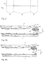
- Fig. 1A bis 1C
- ein erstes Ausführungsbeispiel einer Einstellmechanik eines hier beschriebenen erfindungsgemäßen Fahrzeugsitzes;
- Fig. 2
- eine schematische Höhenprofilsteuerung zwischen verschiedenen Sitzhöhen;
- Fig. 3A bis 3C
- in weiteren schematisch perspektivischen Zeichnungen das Ausführungsbeispiel der
Figuren 1A bis 1C mit weiteren Merkmalen ergänzt; - Fig. 4
- einen hier beschriebenen erfindungsgemäßen Fahrzeugsitz.
- Wie aus der
Figur 1A erkannt werden kann, ist eine Sitzfläche eines Sitzteils 10 zum Platznehmen eines Benutzers des Fahrzeugsitzes 1 zu niedrig eingestellt. Um diese zu niedrige Sitzposition höher zu stellen, umfasst der in derFigur 1A zwar nicht explizit gezeigte, jedoch trotzdem vorhandene Fahrzeugsitz 1, eine Einstellmechanik 22 zum vollautomatischen Einstellen und/oder Begrenzen einer Sitzhöhe S1 des Sitzteils 10 während einer Sitzbelastung des Sitzteils 10 durch einen Benutzer. Dabei umfasst die Einstelleinrichtung 20 zumindest ein einstellbares Betätigungsmittel 21, welches von selbst eine Einstellmechanik 22 der Einstelleinrichtung 20 betätigt, sobald durch die Sitzbelastung des Sitzteils 10 die Sitzhöhe S1 einen durch das Betätigungsmittel 21 vorgegebenen Höhengrenzwert H1 unter- oder überschreitet, sodass die Sitzhöhe S1, insbesondere selbstregulierend, allein durch die Einstelleinrichtung 20 je nach Sitzbelastungsgrad des Sitzteils 10 wieder vollautomatisch zum Höhengrenzwert H1 zurückgeschoben wird. Das Sitzteil 10 wird entlang einer Einfederrichtung H2 gegenüber dem Sitzfuß 11 bewegt. - Insbesondere ist daher der
Figur 1A eine solche Einstelleinrichtung 20 zu entnehmen, welche ein Ventilelement 22A, insbesondere umfassend einen Mikroschalter zum Betätigen des Ventilelements 22A, zum Be- oder Entlüften einer fluidischen Höhenverstelleinrichtung (aus Vereinfachungsgründen nicht gezeigt) zum Einstellen und insbesondere zum Absenken eines Höhenabstandes zwischen dem Sitzteil 10 und dem Sitzfuß 11 aufweist. Zudem umfasst die Einstelleinrichtung 20 ein Schalterelement 23 zum Betätigen einer Fluidpumpe oder eines Fluidkompressors zur Vergrößerung des Höhenabstandes zwischen dem Sitzteil 10 und dem Sitzfuß 11. - Insbesondere kann aus der
Figur 1A erkannt werden, dass das Betätigungsmittel 21 das Ventilelement 22A dann betätigt, wenn der Höhengrenzwert H1 überschritten ist und das Betätigungsmittel 21 das Schalterelement 23, welches ein Zuluftventil umfassen und/oder betätigen kann, dann betätigt, wenn ein Höhengrenzwert H1 unterschritten ist. - Dabei weist die Einstelleinrichtung 20 ein Hebelelement 210 auf, welches ein Teil des Betätigungsmittels 21 ist und wobei das Hebelelement 210 um eine Drehachse X1, welche senkrecht zur Höhenrichtung H1 verläuft, drehbeweglich insbesondere an dem Sitzteil 10 gelagert ist, sodass über eine Höhenbewegung des Sitzteils 10 relativ zum Sitzfuß 11 das Hebelelement 210 des Betätigungsmittels 21 um die Drehachse X1 gedreht wird, sodass in einer ersten Drehstellung des Hebelelements 210 dieses Hebelelement 210 das Ventilelement 22A betätigt (siehe
Figur 1C ) und in einer zweiten Drehstellung des Hebelelements 210 dieses Hebelelement 210 das Schalterelement 23 (sieheFigur 1A ) betätigt. Als rein beispielhaft in denFiguren 1A-1C dargestellt, ist das Hebelelement 210 durch drei sternförmig von der Drehachse X1 wegragenden Hebelstreben gebildet. Eine Hebelstrebe (= Hebelarm 210B) betätigt das Ventilelement 22A und eine andere Hebelstrebe (= Hebelarm 210A) betätigt das Schalterelement 23. - Darüber hinaus ist aus der
Figur 1A erkennbar, dass das Betätigungselement 21 ein Höheneinstellelement 24, im vorliegenden Fall ein Seil, aufweist, welches an einer dritten Hebelstrebe 210C des Hebelelements 210 befestigt ist. Zudem weist das Betätigungselement 21 ein Rückstellelement 25 auf, insbesondere in Form einer Drehfeder, wobei die Drehfeder dafür vorgesehen ist, das Hebelelement 210 um die Drehachse X1 zurückzustellen, sodass ein dauerhafter Rückstelldruck des Hebelelements 210 in Richtung des Schalterelements 23 erzeugt ist. - Besonders eingängig ist aus der
Figur 1A erkennbar, dass das dort dargestellte Höheneinstellelement 24 in Form des Seils erschlafft ist. Dabei ist das Seil mit einem Sitzfuß 11 mechanisch durch ein Federelement 240 verbunden. - Ist nämlich nun das dort gezeigte Seil erschlafft, wird das Hebelelement 210 mittels des ersten Hebelarms 210A automatisch durch die Drehfeder auf das Schalterelement 23 gedrückt. Das Schalterelement 23 wiederum ist mit dem oben genannten Fluidkreislauf, insbesondere einem solchen Kreislauf, welcher eine Fluidpumpe oder einen Fluidkompressor 19 aufweist, verbunden. Es wird also zum Beispiel in ein zwischen dem Sitzfuß 11 und dem Sitzteil 10 verbautes Dämpfungs- und/oder Ausdehnungselement ein Fluid hineingepumpt, sodass über dieses beispielhafte Dämpfungselement das Sitzteil 10 von dem Sitzfuß 11 weggedrängt wird, sodass eine Sitzhöhe S1 immer wieder auf den Höhengrenzwert H1 zurückkehrt (siehe
Figur 1B ). - Dort ist nämlich erkennbar, dass weder das Ventilelement 22A noch das Schalterelement 23 durch das Hebelelement 210 betätigt sind, sodass somit die gesamte Einstellmechanik 22 unbetätigt ist.
- In der
Figur 1C ist der umgekehrte Fall gezeigt, in welchem eine Sitzhöhe S1 des Sitzteils 10 zu hoch ist. Dies kann sich insbesondere durch einen besonders leichten Benutzer ergeben. In diesem Fall ist das Höheneinstellelement 24, also das Seil, sehr stark gespannt und zieht an diesem ersten Hebel 210 den zweiten Hebelarm 210B oder einen dritten Hebelarm 210C gegen das Ventilelement 22A. In diesem Fall wird also statt in eine Dämpfungsmechanik ein Fluid einzupumpen, dieses Fluid aus dieser Dämpfungsmechanik entlassen, sodass sich damit automatisch das Sitzteil 10 auf den Sitzfuß 11 auf den Höhengrenzwert H1 hinabsenkt, ab dem die Feder nur noch derart leicht gespannt ist, dass sich eine Drehkraft zwischen den Rückstellelement 25 und der durch das Höheneinstellelement 24 die auf den Hebel 210 ausgeübte Kraft genau aufhebt und sich daher wie in derFigur 1C ein Ausgleichszustand ergibt, sodass sich daher der in derFigur 1C zu hoch eingestellte Sitz automatisch auf den Höhengrenzwert H1 derFigur 1B hineinbewegt. - In den
Figuren 3A bis 3C sind in weiteren schematisch perspektivischen Zeichnungen das Ausführungsbeispiel derFiguren 1A bis 1C mit weiteren Merkmalen ergänzt dargestellt. - Ein Unterschied liegt bereits darin, dass auf separate Hebelarme 210A, 210B verzichtet ist und stattdessen ein um die Drehachse X drehbeweglicher Keil 210D gewählt wurde, wobei eine Seitenfläche dieses Keils 210D das Ventilelement 22A betätigt. Ein Hebelarm 210 betätigt das Schalterelement 23 je nach Drehstellung.
- Das Höheneinstellelement 24, also vorliegend das Seil, ist an einem Fortsatz 210E des Keils 210D befestigt. Zudem ist, wie aus den
Figuren 3A bis 3C offensichtlich, dass das Seil in derFigur 3A nicht gespannt ist. In derFigur 3B ist es zwar gespannt, jedoch nur soweit dass eine Rückstellkraft der Drehfeder aufgehoben wird und in derFigur 3C überwiegt zunächst die Kraft des Seil, wodurch die Seitenfläche des Keils 210D gegen das Ventilelement 22A gedrängt wird. Insofern ist die Funktionsweise der in denFiguren 3A bis 3C gezeigten Vorrichtung die gleiche wie die Funktionsweise der in denFiguren 1A bis 1C gezeigten Vorrichtung. - In der
Figur 2 sind rein schematisch ein oberer Restfederweg R1 sowie ein unterer Restfederweg R2 angegeben. Der untere Restfederweg R2 ist ein solcher Federweg, welcher zum Beispiel von einer Federhöhe 0 mm bis 50 mm reicht, wobei der obere Restfederweg R1 vorliegend einen Federweg zwischen 130 und 180 mm aufweist. Dazwischen befindet sich ein Normhöhennutzungsbereich N2. Mittels eines Hebel- und/oder Schieber- und/oder Ratschenelements kann eine Seillänge innerhalb des Normhöhennutzungsbereiches N2 eingestellt werden. Eine Veränderung der Seillänge kann jedoch nicht bis in die Restwegfederlängen R1, R2 hineinführen. Mit anderen Worten kann ein Gleichgewichtszustand vorzugsweise lediglich innerhalb des Normhöhennutzungsbereichs N2 eingestellt werden. Die Restfederwege R1, R2 sind daher vorzugsweise solche Federstrecken, in welche der Sitz ein- oder ausfedern kann, jedoch selbstständig auf einen vorgebbaren Gleichgewichtswert innerhalb des Normhöhennutzungsbereichs N2 zurückkehrt. - In der
Figur 4 ist in einer schematisch perspektivischen Ansicht ein Ausführungsbeispiel eines erfindungsgemäßen Fahrzeugsitzes 1 gezeigt. Dabei zeigt dieFigur 4 den Fahrzeugsitz 1 vollständig, wobei dieFiguren 3A bis 3C Seitenansichten eines Ausschnitts dieses Fahrzeugsitzes 1 zeigen. Zunächst ist erkennbar, dass das höhenverstellbare Verbindungsgestell 13 ein Scherengestell aufweist, welches zumindest zwei Scherenarme 13A, 13B umfasst, die zwischen dem Sitzteil 10 und dem Sitzfuß 11 angeordnet sind. - Besonders deutlich ist in der
Figur 4 eine Umlenkmechanik mittel zumindest eines Umlenkrades 26 erkennbar. Das Umlenkrad 26 ist im Sitzfuß 11 verbaut, sodass eine in horizontaler Richtung (senkrecht zur Einfederrichtung) das Federelement 240 verbaut ist. Zudem ist das Rückstellelement 25 in Form der Drehfeder erkennbar. - Darüber hinaus ist eine Hebel- und/oder Schiebemechanik 27 dargestellt, über welche eine Seillänge voreingestellt werden kann. Dabei kann es sich um einen Hebel handeln, welcher ebenso parallel um die Drehachse X drehbar ist, wobei an einem Hebelarm dann ein Seilende befestigt ist, und das andere Seilende an dem Sitzfuß 11 befestigt ist.
- In der
Figur 4 ist rein beispielhaft ein Drehschieber 270 dargestellt, welcher in der horizontalen Richtung H3 verschoben und/oder um eine zur horizontalen Richtung H3 parallele Achse verschwenkt werden kann. Ein oberes Seilende ist daher mechanisch direkt oder indirekt an dem Drehschieber 270 verbunden. Das Betätigungsmittel 21 betätigt, wie aus denFiguren 3A bis 3C erkennbar, nicht nur das Ventilelement 22A und das Schalterelement 23 sondern ist ebenso ein Umleitelement für das Seil um dieses in die horizontale Richtung H3 wieder umleiten zu können. -
- 1
- Fahrzeugsitz
- 10
- Sitzteil
- 11
- Sitzfuß
- 12
- Träger
- 13
- Verbindungsgestell
- 13A
- Scherenarm
- 13B
- Scherenarm
- 20
- Einstelleinrichtung
- 21
- Betätigungsmittel
- 21A
- Pleuelelement
- 22
- Einstellmechanik
- 22A
- Ventilelement
- 23
- Schalterelement
- 24
- Höheneinstellelement
- 25
- Rückstellelement
- 26
- Umlenkrad
- 27
- Hebel- und oder Schiebemechanik
- 210
- Hebelelement
- 210A
- erster Hebelarm
- 210B
- zweiter Hebelarm
- 210C
- dritter Hebelarm
- 210D
- Keil
- 210E
- Fortsatz
- 240
- Federelement
- 270
- Drehschieber
- H1
- Höhengrenzwert
- H2
- Einfederrichtung
- H3
- horizontale Richtung
- R1
- oberer Restfederweg
- R2
- unterer Restfederweg
- S1
- Sitzhöhe
- VEH1
- voreingestellte Höhe
- X1
- Drehachse
- ZH1
- Zielhöhe
Claims (7)
- Fahrzeugsitz (1), mit- einem Sitzteil (10) zum Platznehmen eines Benutzers des Fahrzeugsitzes (1),- zumindest einem Sitzfuß (11) zur Montage des Fahrzeugsitzes (1) auf einem Fahrzeugboden,- einem höhenverstellbaren Verbindungsgestell (13), welches das Sitzteil (10) mit dem Sitzfuß (11) mechanisch miteinander verbindet, sodass das Sitzteil (10) in Höhenrichtung gegenüber dem Sitzfuß (11) bewegbar ist, wobei zumindest eine Einstelleinrichtung (20) zum vollautomatischen Einstellen und/oder Begrenzen einer Sitzhöhe (S1) des Sitzteils (10) während einer Sitzbelastung des Sitzteils (10) durch den Benutzer, wobei die Einstelleinrichtung (20) zumindest ein einstellbares Betätigungsmittel (21) umfasst, welches von selbst eine Einstellmechanik (22) der Einstelleinrichtung (20) betätigt, sobald durch die Sitzbelastung des Sitzteils (10) die Sitzhöhe (S1) einen durch das Betätigungsmittel (21) vorgegebenen Höhengrenzwert (H1) unter- oder überschreitet, sodass die Sitzhöhe (S1) selbstregulierend, durch die Einstelleinrichtung (20) je nach Sitzbelastungsgrad des Sitzteils (10) wieder in den Höhengrenzwert (H1) vollautomatisch zurückverschoben wird, wobei die Einstelleinrichtung (20)- zumindest ein Ventilelement (22A) zum Be- oder Entlüften einer fluidischen Höhenverstelleinrichtung zum Einstellen zum Absenken eines Höhenabstandes zwischen dem Sitzteil (10) und dem Sitzfuß (11), und- zumindest ein Schalterelement (23) zum Betätigen einer Fluidpumpe zur Vergrößerung des Höhenabstandes zwischen dem Sitzteil (10) und dem Sitzfuß (11) aufweist, wobeidas Betätigungsmittel (21) das Ventilelement (22A) dann betätigt, wenn der Höhengrenzwert (H1) überschritten ist, und das Betätigungsmittel (21) das Schalterelement (23) dann betätigt, wenn ein Höhengrenzwert (H1) unterschritten ist, dadurch gekennzeichnet, dass ein Hebelelement (210), umfassend drei sternförmig von einer Drehachse (X1) wegragende Hebelstreben (210A, 210B, 210C), des Betätigungsmittels (21) um die Drehachse (X1), welche senkrecht zur Höhenrichtung verläuft, drehbeweglich an dem Sitzfuß (11) oder an dem Sitzteil (10), gelagert ist, sodass über eine Höhenbewegung des Sitzteils (10) relativ zum Sitzfuß (11) das Hebelelement (210) des Betätigungselements (21) um diese Drehachse (X1) gedreht wird, sodass in einer ersten Drehstellung des Hebelelements (210) eine erste Hebelstrebe (210B) das Ventilelement (22A) betätigt und in einer zweiten Drehstellung des Hebelelements (210) eine zweite Hebelstrebe (210A) das Schalterelement (23) betätigt, wobei das Betätigungselement (21) ein Höheneinstellelement (24) aufweist, welches an einer dritten Hebelstrebe (210C) befestigt ist.
- Fahrzeugsitz (1) nach Anspruch 1,
dadurch gekennzeichnet, dass
das Betätigungselement (21)- das Höheneinstellelement (24) sowie- zumindest ein Rückstellelement (25) zum Rückstellen des Hebelelements (210) um die Drehachse (X1)
aufweist. - Fahrzeugsitz (1) nach Anspruch 2,
dadurch gekennzeichnet, dass
das Höheneinstellelement (24) ein Seil ist und das Rückstellelement (25) eine Drehfeder ist. - Fahrzeugsitz (1) nach Anspruch 3,
dadurch gekennzeichnet, dass das Höheneinstellelement (24) zumindest ein vorspannbares, Feder- und/oder Dämpfungselement (240) und/oder Ratschen- und/oder Schieberelement aufweist, mittels welchem eine Länge, und/oder Vorspanngrad des Höheneinstellelements (24) einstellbar ist. - Fahrzeugsitz (1) nach zumindest einem der vorhergehenden Ansprüche,
dadurch gekennzeichnet, dass
das höhenverstellbare Verbindungsgestell (13) ein Scherengestell aufweist, welches zumindest zwei Scherenarme (13A, 13B) umfasst, die zwischen dem Sitzteil (10) und dem Sitzfuß (11) angeordnet sind. - Fahrzeugsitz (1) nach zumindest einem der vorhergehenden Ansprüche,
dadurch gekennzeichnet, dass
die Einstelleinrichtung (20) frei von eine rein elektronischen Steuer- und/oder Regeleinrichtung, sodass eine Einstellung mechanisch erfolgt. - Verfahren zur vollautomatischen Höheneinstellung eines Fahrzeugsitzes (1) nach einem der Ansprüche 1 bis 6, mit- einem Sitzteil (10) zum Platznehmen eines Benutzers des Fahrzeugsitzes (1),- zumindest einem Sitzfuß (11) zur Montage des Fahrzeugsitzes (1) auf einem Fahrzeugboden,- einem höhenverstellbaren Verbindungsgestell (13), welches das Sitzteil (10) mit dem Sitzfuß (11) mechanisch miteinander verbindet, sodass das Sitzteil (10) in Höhenrichtung gegenüber dem Sitzfuß (11) bewegbar ist,gekennzeichnet, durch
zumindest eine Einstelleinrichtung (20) zum vollautomatischen Einstellen und/oder Begrenzen einer Sitzhöhe (S1) des Sitzteils (10) während einer Sitzbelastung des Sitzteils (10) durch den Benutzer, wobei die Einstelleinrichtung (20) zumindest ein einstellbares Betätigungsmittel (21) umfasst, welches von selbst eine Einstellmechanik (22) der Einstelleinrichtung (20) betätigt, sobald durch die Sitzbelastung des Sitzteils (10) die Sitzhöhe (S1) einen durch das Betätigungsmittel (21) vorgegebenen Höhengrenzwert (H1) unter- oder überschreitet, sodass die Sitzhöhe (S1) selbstregulierend durch die Einstelleinrichtung (20) je nach Sitzbelastungsgrad des Sitzteils (10) wieder in den Höhengrenzwert (H11) vollautomatisch zurückverschoben wird.
Applications Claiming Priority (1)
| Application Number | Priority Date | Filing Date | Title |
|---|---|---|---|
| DE102018122082.0A DE102018122082B4 (de) | 2018-09-11 | 2018-09-11 | Fahrzeugsitz |
Publications (2)
| Publication Number | Publication Date |
|---|---|
| EP3623211A1 EP3623211A1 (de) | 2020-03-18 |
| EP3623211B1 true EP3623211B1 (de) | 2021-11-03 |
Family
ID=67928641
Family Applications (1)
| Application Number | Title | Priority Date | Filing Date |
|---|---|---|---|
| EP19196560.7A Active EP3623211B1 (de) | 2018-09-11 | 2019-09-10 | Fahrzeugsitz |
Country Status (4)
| Country | Link |
|---|---|
| EP (1) | EP3623211B1 (de) |
| CN (1) | CN110884394B (de) |
| BR (1) | BR102019018828B1 (de) |
| DE (1) | DE102018122082B4 (de) |
Families Citing this family (1)
| Publication number | Priority date | Publication date | Assignee | Title |
|---|---|---|---|---|
| DE102021133628B4 (de) * | 2021-12-17 | 2024-02-01 | Grammer Aktiengesellschaft | Fahrzeugsitz und Verfahren zur Ausgabe einer Position eines Oberteils zu einem Unterteil des Fahrzeugsitzes |
Citations (1)
| Publication number | Priority date | Publication date | Assignee | Title |
|---|---|---|---|---|
| DE3312732A1 (de) * | 1983-04-07 | 1984-10-11 | Gebr. Isringhausen, 4920 Lemgo | Verfahren zur ueberwachung der soll-mittellage von luftsitzen |
Family Cites Families (22)
| Publication number | Priority date | Publication date | Assignee | Title |
|---|---|---|---|---|
| DE2753105A1 (de) | 1977-11-29 | 1979-06-07 | Isringhausen Geb | Luftgefederter fahrzeugsitz |
| DE3136756A1 (de) * | 1981-09-16 | 1983-07-07 | Fa. Willibald Grammer, 8450 Amberg | Luftgefederter fahrzeugsitz |
| DE3333604A1 (de) | 1983-09-14 | 1985-03-28 | Gebr. Isringhausen, 4920 Lemgo | Luftgefederter fahrzeugsitz |
| GB2243998A (en) * | 1990-05-16 | 1991-11-20 | Kab Seating Ltd | Seat suspension system |
| DE4025183C1 (de) | 1990-08-09 | 1991-11-14 | Grammer Ag, 8450 Amberg, De | |
| JP3376887B2 (ja) * | 1997-10-13 | 2003-02-10 | トヨタ自動車株式会社 | 車両用シート |
| DE10354635B4 (de) * | 2003-11-22 | 2006-09-07 | Grammer Ag | Fahrzeugsitz mit automatischer Höheneinstellung und Verfahren hierfür |
| JP5043385B2 (ja) * | 2006-08-24 | 2012-10-10 | マツダ株式会社 | 自動車用シート装置 |
| DE202007002243U1 (de) * | 2007-02-15 | 2007-04-19 | Festo Ag & Co | Höheneinstellvorrichtung eines Fahrzeugsitzes und damit ausgestatteter Fahrzeugsitz |
| DE102008022046B3 (de) * | 2008-05-03 | 2009-07-30 | Grammer Ag | Einrichtung für eine Fahrzeugsitzbelegungserkennung |
| DE102008056200B4 (de) * | 2008-11-06 | 2014-04-03 | Grammer Aktiengesellschaft | Scherengestell für einen Fahrzeugsitz, Fahrzeugsitz, insbesondere Kraftfahrzeugsitz, und Verfahren zum Herstellen eines Unterbaus eines Fahrzeugsitzes |
| CN102019864B (zh) * | 2009-09-22 | 2012-10-24 | 厦门金龙汽车座椅有限公司 | 车辆座椅减震器 |
| DE102010046799B4 (de) * | 2010-09-22 | 2012-06-06 | Keiper Gmbh & Co. Kg | Fahrzeugsitz, insbesondere Nutzfahrzeugsitz |
| JP5692536B2 (ja) * | 2011-10-24 | 2015-04-01 | アイシン精機株式会社 | シート駆動装置 |
| DE102013104748A1 (de) * | 2013-05-08 | 2014-11-27 | Dr. Ing. H.C. F. Porsche Aktiengesellschaft | Verstellanordnung für einen Kraftfahrzeugsitz |
| DE102013110923B4 (de) * | 2013-10-01 | 2019-07-04 | Grammer Ag | Fahrzeugsitz oder Fahrzeugkabine mit einer Federungseinrichtung und Nutzkraftfahrzeug |
| DE102013110927B4 (de) | 2013-10-01 | 2020-09-03 | Grammer Aktiengesellschaft | Fahrzeugsitz oder Fahrzeugkabine mit einer Federungseinrichtung und Nutzkraftfahrzeug |
| JP6192221B2 (ja) * | 2013-11-18 | 2017-09-06 | 株式会社タチエス | シート |
| DE102015214532B4 (de) * | 2015-03-18 | 2022-06-09 | Adient Luxembourg Holding S.À R.L. | Höheneinstellvorrichtung für einen Fahrzeugsitz, insbesondere Nutzfahrzeugsitz, sowie Fahrzeugsitz, insbesondere Nutzfahrzeugsitz |
| DE102016107625B4 (de) * | 2016-04-25 | 2021-08-12 | Grammer Aktiengesellschaft | Regelbares Dämpfungssystem für einen Fahrzeugsitz |
| CN206155231U (zh) * | 2016-10-19 | 2017-05-10 | 河北光华荣昌汽车部件有限公司 | 一种具有高度调整以及悬浮功能的座椅 |
| DE102016124696B4 (de) * | 2016-12-16 | 2018-12-13 | Grammer Aktiengesellschaft | Fahrzeugkabine oder Fahrzeugsitz mit Höhenverstelleinrichtung |
-
2018
- 2018-09-11 DE DE102018122082.0A patent/DE102018122082B4/de active Active
-
2019
- 2019-09-10 EP EP19196560.7A patent/EP3623211B1/de active Active
- 2019-09-11 CN CN201910860950.4A patent/CN110884394B/zh active Active
- 2019-09-11 BR BR102019018828-6A patent/BR102019018828B1/pt active IP Right Grant
Patent Citations (1)
| Publication number | Priority date | Publication date | Assignee | Title |
|---|---|---|---|---|
| DE3312732A1 (de) * | 1983-04-07 | 1984-10-11 | Gebr. Isringhausen, 4920 Lemgo | Verfahren zur ueberwachung der soll-mittellage von luftsitzen |
Also Published As
| Publication number | Publication date |
|---|---|
| CN110884394A (zh) | 2020-03-17 |
| DE102018122082B4 (de) | 2023-04-27 |
| EP3623211A1 (de) | 2020-03-18 |
| BR102019018828A2 (pt) | 2020-05-26 |
| BR102019018828B1 (pt) | 2023-12-12 |
| CN110884394B (zh) | 2022-02-25 |
| DE102018122082A1 (de) | 2020-03-12 |
Similar Documents
| Publication | Publication Date | Title |
|---|---|---|
| EP2271514B1 (de) | Betätigungseinheit eines kraftfahrzeugsitzes | |
| EP3263396B1 (de) | Federungsvorrichtung | |
| EP0962356B1 (de) | Längsführung eines Fahrzeugsitzes mit Arretiervorrichtung | |
| EP2571720A2 (de) | Verstellvorrichtung für kraftfahrzeugsitze, insbesondere höhenverstellvorrichtungen | |
| WO2009033570A2 (de) | Verstelleinrichtung zur längsverstellung einer kraftfahrzeugkomponente | |
| WO2005084999A1 (de) | Vorrichtung zur winkelverstellung einer um eine drehachse drehbar vorgesehenen komponente, insbesondere einer armlehne in einem fahrzeug | |
| EP0739853A1 (de) | Sicherheitseinrichtung für Personenförderanlagen | |
| DE102015214532A1 (de) | Höheneinstellvorrichtung für einen Fahrzeugsitz, insbesondere Nutzfahrzeugsitz, sowie Fahrzeugsitz, insbesondere Nutzfahrzeugsitz | |
| EP3623211B1 (de) | Fahrzeugsitz | |
| DE102005029235A1 (de) | Armlehne für einen Fahrzeugsitz und Fahrzeugsitz | |
| EP1244566A1 (de) | Vorrichtung zum verstellen der neigung einer sitzplatte eines fahrzeugsitzes | |
| EP3486115A1 (de) | Ausstattungsvorrichtung des fahrzeuginnenraums | |
| DE102017205699B4 (de) | Vorrichtung zum Kippen der Rückenlehne von Bürostühlen | |
| DE102005043333B4 (de) | Kraftfahrzeugsitz mit einem in der Höhe verstellbaren Sitzkissen und einem mit dem Sitzkissen verbundenen Befestigungspunkt für einen Sicherheitsgurt | |
| DE202009010587U1 (de) | Armlehne, insbesondere für einen Bürostuhl | |
| DE102015000841B4 (de) | Stützvorrichtung | |
| DE19628716C2 (de) | Betätigungsvorrichtung für Verstelleinrichtungen in Kraftfahrzeugen | |
| EP3623210B1 (de) | Fahrzeugsitz | |
| EP0845384A1 (de) | Verriegelungsvorrichtung an Längsverstelleinrichtungen für Sitze, insbesondere Kraftfahrzeugsitze | |
| DE69714910T2 (de) | Verstellvorrichtung | |
| DE3035891C2 (de) | Vorrichtung zum Feststellen von um vorzugsweise horizontale Achsen schwenkbar gelagerten Bauteilen | |
| WO2002091880A1 (de) | Bürostuhl | |
| DE20218691U1 (de) | Stativ für ein Operationsmikroskop | |
| EP2620714B1 (de) | Lüftungsvorrichtung für Räume | |
| DE10218394A1 (de) | Sitz |
Legal Events
| Date | Code | Title | Description |
|---|---|---|---|
| PUAI | Public reference made under article 153(3) epc to a published international application that has entered the european phase |
Free format text: ORIGINAL CODE: 0009012 |
|
| STAA | Information on the status of an ep patent application or granted ep patent |
Free format text: STATUS: THE APPLICATION HAS BEEN PUBLISHED |
|
| AK | Designated contracting states |
Kind code of ref document: A1 Designated state(s): AL AT BE BG CH CY CZ DE DK EE ES FI FR GB GR HR HU IE IS IT LI LT LU LV MC MK MT NL NO PL PT RO RS SE SI SK SM TR |
|
| AX | Request for extension of the european patent |
Extension state: BA ME |
|
| STAA | Information on the status of an ep patent application or granted ep patent |
Free format text: STATUS: REQUEST FOR EXAMINATION WAS MADE |
|
| 17P | Request for examination filed |
Effective date: 20200602 |
|
| RBV | Designated contracting states (corrected) |
Designated state(s): AL AT BE BG CH CY CZ DE DK EE ES FI FR GB GR HR HU IE IS IT LI LT LU LV MC MK MT NL NO PL PT RO RS SE SI SK SM TR |
|
| RAP1 | Party data changed (applicant data changed or rights of an application transferred) |
Owner name: GRAMMER AG |
|
| STAA | Information on the status of an ep patent application or granted ep patent |
Free format text: STATUS: EXAMINATION IS IN PROGRESS |
|
| 17Q | First examination report despatched |
Effective date: 20210223 |
|
| GRAP | Despatch of communication of intention to grant a patent |
Free format text: ORIGINAL CODE: EPIDOSNIGR1 |
|
| STAA | Information on the status of an ep patent application or granted ep patent |
Free format text: STATUS: GRANT OF PATENT IS INTENDED |
|
| INTG | Intention to grant announced |
Effective date: 20210818 |
|
| GRAS | Grant fee paid |
Free format text: ORIGINAL CODE: EPIDOSNIGR3 |
|
| GRAA | (expected) grant |
Free format text: ORIGINAL CODE: 0009210 |
|
| STAA | Information on the status of an ep patent application or granted ep patent |
Free format text: STATUS: THE PATENT HAS BEEN GRANTED |
|
| AK | Designated contracting states |
Kind code of ref document: B1 Designated state(s): AL AT BE BG CH CY CZ DE DK EE ES FI FR GB GR HR HU IE IS IT LI LT LU LV MC MK MT NL NO PL PT RO RS SE SI SK SM TR |
|
| REG | Reference to a national code |
Ref country code: GB Ref legal event code: FG4D Free format text: NOT ENGLISH |
|
| REG | Reference to a national code |
Ref country code: AT Ref legal event code: REF Ref document number: 1443674 Country of ref document: AT Kind code of ref document: T Effective date: 20211115 Ref country code: CH Ref legal event code: EP |
|
| REG | Reference to a national code |
Ref country code: IE Ref legal event code: FG4D Free format text: LANGUAGE OF EP DOCUMENT: GERMAN |
|
| REG | Reference to a national code |
Ref country code: DE Ref legal event code: R096 Ref document number: 502019002642 Country of ref document: DE |
|
| REG | Reference to a national code |
Ref country code: LT Ref legal event code: MG9D |
|
| REG | Reference to a national code |
Ref country code: NL Ref legal event code: MP Effective date: 20211103 |
|
| PG25 | Lapsed in a contracting state [announced via postgrant information from national office to epo] |
Ref country code: RS Free format text: LAPSE BECAUSE OF FAILURE TO SUBMIT A TRANSLATION OF THE DESCRIPTION OR TO PAY THE FEE WITHIN THE PRESCRIBED TIME-LIMIT Effective date: 20211103 Ref country code: LT Free format text: LAPSE BECAUSE OF FAILURE TO SUBMIT A TRANSLATION OF THE DESCRIPTION OR TO PAY THE FEE WITHIN THE PRESCRIBED TIME-LIMIT Effective date: 20211103 Ref country code: FI Free format text: LAPSE BECAUSE OF FAILURE TO SUBMIT A TRANSLATION OF THE DESCRIPTION OR TO PAY THE FEE WITHIN THE PRESCRIBED TIME-LIMIT Effective date: 20211103 Ref country code: BG Free format text: LAPSE BECAUSE OF FAILURE TO SUBMIT A TRANSLATION OF THE DESCRIPTION OR TO PAY THE FEE WITHIN THE PRESCRIBED TIME-LIMIT Effective date: 20220203 |
|
| PG25 | Lapsed in a contracting state [announced via postgrant information from national office to epo] |
Ref country code: IS Free format text: LAPSE BECAUSE OF FAILURE TO SUBMIT A TRANSLATION OF THE DESCRIPTION OR TO PAY THE FEE WITHIN THE PRESCRIBED TIME-LIMIT Effective date: 20220303 Ref country code: SE Free format text: LAPSE BECAUSE OF FAILURE TO SUBMIT A TRANSLATION OF THE DESCRIPTION OR TO PAY THE FEE WITHIN THE PRESCRIBED TIME-LIMIT Effective date: 20211103 Ref country code: PT Free format text: LAPSE BECAUSE OF FAILURE TO SUBMIT A TRANSLATION OF THE DESCRIPTION OR TO PAY THE FEE WITHIN THE PRESCRIBED TIME-LIMIT Effective date: 20220303 Ref country code: PL Free format text: LAPSE BECAUSE OF FAILURE TO SUBMIT A TRANSLATION OF THE DESCRIPTION OR TO PAY THE FEE WITHIN THE PRESCRIBED TIME-LIMIT Effective date: 20211103 Ref country code: NO Free format text: LAPSE BECAUSE OF FAILURE TO SUBMIT A TRANSLATION OF THE DESCRIPTION OR TO PAY THE FEE WITHIN THE PRESCRIBED TIME-LIMIT Effective date: 20220203 Ref country code: NL Free format text: LAPSE BECAUSE OF FAILURE TO SUBMIT A TRANSLATION OF THE DESCRIPTION OR TO PAY THE FEE WITHIN THE PRESCRIBED TIME-LIMIT Effective date: 20211103 Ref country code: LV Free format text: LAPSE BECAUSE OF FAILURE TO SUBMIT A TRANSLATION OF THE DESCRIPTION OR TO PAY THE FEE WITHIN THE PRESCRIBED TIME-LIMIT Effective date: 20211103 Ref country code: HR Free format text: LAPSE BECAUSE OF FAILURE TO SUBMIT A TRANSLATION OF THE DESCRIPTION OR TO PAY THE FEE WITHIN THE PRESCRIBED TIME-LIMIT Effective date: 20211103 Ref country code: GR Free format text: LAPSE BECAUSE OF FAILURE TO SUBMIT A TRANSLATION OF THE DESCRIPTION OR TO PAY THE FEE WITHIN THE PRESCRIBED TIME-LIMIT Effective date: 20220204 Ref country code: ES Free format text: LAPSE BECAUSE OF FAILURE TO SUBMIT A TRANSLATION OF THE DESCRIPTION OR TO PAY THE FEE WITHIN THE PRESCRIBED TIME-LIMIT Effective date: 20211103 |
|
| PG25 | Lapsed in a contracting state [announced via postgrant information from national office to epo] |
Ref country code: SM Free format text: LAPSE BECAUSE OF FAILURE TO SUBMIT A TRANSLATION OF THE DESCRIPTION OR TO PAY THE FEE WITHIN THE PRESCRIBED TIME-LIMIT Effective date: 20211103 Ref country code: SK Free format text: LAPSE BECAUSE OF FAILURE TO SUBMIT A TRANSLATION OF THE DESCRIPTION OR TO PAY THE FEE WITHIN THE PRESCRIBED TIME-LIMIT Effective date: 20211103 Ref country code: RO Free format text: LAPSE BECAUSE OF FAILURE TO SUBMIT A TRANSLATION OF THE DESCRIPTION OR TO PAY THE FEE WITHIN THE PRESCRIBED TIME-LIMIT Effective date: 20211103 Ref country code: EE Free format text: LAPSE BECAUSE OF FAILURE TO SUBMIT A TRANSLATION OF THE DESCRIPTION OR TO PAY THE FEE WITHIN THE PRESCRIBED TIME-LIMIT Effective date: 20211103 Ref country code: DK Free format text: LAPSE BECAUSE OF FAILURE TO SUBMIT A TRANSLATION OF THE DESCRIPTION OR TO PAY THE FEE WITHIN THE PRESCRIBED TIME-LIMIT Effective date: 20211103 Ref country code: CZ Free format text: LAPSE BECAUSE OF FAILURE TO SUBMIT A TRANSLATION OF THE DESCRIPTION OR TO PAY THE FEE WITHIN THE PRESCRIBED TIME-LIMIT Effective date: 20211103 |
|
| REG | Reference to a national code |
Ref country code: DE Ref legal event code: R097 Ref document number: 502019002642 Country of ref document: DE |
|
| PLBE | No opposition filed within time limit |
Free format text: ORIGINAL CODE: 0009261 |
|
| STAA | Information on the status of an ep patent application or granted ep patent |
Free format text: STATUS: NO OPPOSITION FILED WITHIN TIME LIMIT |
|
| 26N | No opposition filed |
Effective date: 20220804 |
|
| PG25 | Lapsed in a contracting state [announced via postgrant information from national office to epo] |
Ref country code: AL Free format text: LAPSE BECAUSE OF FAILURE TO SUBMIT A TRANSLATION OF THE DESCRIPTION OR TO PAY THE FEE WITHIN THE PRESCRIBED TIME-LIMIT Effective date: 20211103 |
|
| PG25 | Lapsed in a contracting state [announced via postgrant information from national office to epo] |
Ref country code: SI Free format text: LAPSE BECAUSE OF FAILURE TO SUBMIT A TRANSLATION OF THE DESCRIPTION OR TO PAY THE FEE WITHIN THE PRESCRIBED TIME-LIMIT Effective date: 20211103 |
|
| PG25 | Lapsed in a contracting state [announced via postgrant information from national office to epo] |
Ref country code: MC Free format text: LAPSE BECAUSE OF FAILURE TO SUBMIT A TRANSLATION OF THE DESCRIPTION OR TO PAY THE FEE WITHIN THE PRESCRIBED TIME-LIMIT Effective date: 20211103 |
|
| REG | Reference to a national code |
Ref country code: CH Ref legal event code: PL |
|
| REG | Reference to a national code |
Ref country code: BE Ref legal event code: MM Effective date: 20220930 |
|
| PG25 | Lapsed in a contracting state [announced via postgrant information from national office to epo] |
Ref country code: LU Free format text: LAPSE BECAUSE OF NON-PAYMENT OF DUE FEES Effective date: 20220910 |
|
| PG25 | Lapsed in a contracting state [announced via postgrant information from national office to epo] |
Ref country code: LI Free format text: LAPSE BECAUSE OF NON-PAYMENT OF DUE FEES Effective date: 20220930 Ref country code: CH Free format text: LAPSE BECAUSE OF NON-PAYMENT OF DUE FEES Effective date: 20220930 Ref country code: IE Free format text: LAPSE BECAUSE OF NON-PAYMENT OF DUE FEES Effective date: 20220910 |
|
| PG25 | Lapsed in a contracting state [announced via postgrant information from national office to epo] |
Ref country code: BE Free format text: LAPSE BECAUSE OF NON-PAYMENT OF DUE FEES Effective date: 20220930 |
|
| PG25 | Lapsed in a contracting state [announced via postgrant information from national office to epo] |
Ref country code: HU Free format text: LAPSE BECAUSE OF FAILURE TO SUBMIT A TRANSLATION OF THE DESCRIPTION OR TO PAY THE FEE WITHIN THE PRESCRIBED TIME-LIMIT; INVALID AB INITIO Effective date: 20190910 |
|
| PG25 | Lapsed in a contracting state [announced via postgrant information from national office to epo] |
Ref country code: CY Free format text: LAPSE BECAUSE OF FAILURE TO SUBMIT A TRANSLATION OF THE DESCRIPTION OR TO PAY THE FEE WITHIN THE PRESCRIBED TIME-LIMIT Effective date: 20211103 |
|
| PG25 | Lapsed in a contracting state [announced via postgrant information from national office to epo] |
Ref country code: MK Free format text: LAPSE BECAUSE OF FAILURE TO SUBMIT A TRANSLATION OF THE DESCRIPTION OR TO PAY THE FEE WITHIN THE PRESCRIBED TIME-LIMIT Effective date: 20211103 |
|
| PG25 | Lapsed in a contracting state [announced via postgrant information from national office to epo] |
Ref country code: MT Free format text: LAPSE BECAUSE OF FAILURE TO SUBMIT A TRANSLATION OF THE DESCRIPTION OR TO PAY THE FEE WITHIN THE PRESCRIBED TIME-LIMIT Effective date: 20211103 |
|
| PGFP | Annual fee paid to national office [announced via postgrant information from national office to epo] |
Ref country code: DE Payment date: 20250919 Year of fee payment: 7 |
|
| PGFP | Annual fee paid to national office [announced via postgrant information from national office to epo] |
Ref country code: GB Payment date: 20250923 Year of fee payment: 7 |
|
| PGFP | Annual fee paid to national office [announced via postgrant information from national office to epo] |
Ref country code: FR Payment date: 20250924 Year of fee payment: 7 |
|
| REG | Reference to a national code |
Ref country code: AT Ref legal event code: MM01 Ref document number: 1443674 Country of ref document: AT Kind code of ref document: T Effective date: 20240910 |
|
| PG25 | Lapsed in a contracting state [announced via postgrant information from national office to epo] |
Ref country code: TR Free format text: LAPSE BECAUSE OF FAILURE TO SUBMIT A TRANSLATION OF THE DESCRIPTION OR TO PAY THE FEE WITHIN THE PRESCRIBED TIME-LIMIT Effective date: 20211103 |
|
| PG25 | Lapsed in a contracting state [announced via postgrant information from national office to epo] |
Ref country code: AT Free format text: LAPSE BECAUSE OF NON-PAYMENT OF DUE FEES Effective date: 20240910 |
|
| PGFP | Annual fee paid to national office [announced via postgrant information from national office to epo] |
Ref country code: IT Payment date: 20250930 Year of fee payment: 7 |
|
| PGFP | Annual fee paid to national office [announced via postgrant information from national office to epo] |
Ref country code: AT Payment date: 20260410 Year of fee payment: 5 |