EP3622870A1 - Bodendüse mit einer radanordnung, staubsauger mit einer bodendüse und verfahren zur herstellung einer bodendüse - Google Patents
Bodendüse mit einer radanordnung, staubsauger mit einer bodendüse und verfahren zur herstellung einer bodendüse Download PDFInfo
- Publication number
- EP3622870A1 EP3622870A1 EP19194530.2A EP19194530A EP3622870A1 EP 3622870 A1 EP3622870 A1 EP 3622870A1 EP 19194530 A EP19194530 A EP 19194530A EP 3622870 A1 EP3622870 A1 EP 3622870A1
- Authority
- EP
- European Patent Office
- Prior art keywords
- floor nozzle
- axis
- nozzle
- wheel
- nozzle body
- Prior art date
- Legal status (The legal status is an assumption and is not a legal conclusion. Google has not performed a legal analysis and makes no representation as to the accuracy of the status listed.)
- Granted
Links
Images


Classifications
-
- A—HUMAN NECESSITIES
- A47—FURNITURE; DOMESTIC ARTICLES OR APPLIANCES; COFFEE MILLS; SPICE MILLS; SUCTION CLEANERS IN GENERAL
- A47L—DOMESTIC WASHING OR CLEANING; SUCTION CLEANERS IN GENERAL
- A47L9/00—Details or accessories of suction cleaners, e.g. mechanical means for controlling the suction or for effecting pulsating action; Storing devices specially adapted to suction cleaners or parts thereof; Carrying-vehicles specially adapted for suction cleaners
- A47L9/009—Carrying-vehicles; Arrangements of trollies or wheels; Means for avoiding mechanical obstacles
-
- A—HUMAN NECESSITIES
- A47—FURNITURE; DOMESTIC ARTICLES OR APPLIANCES; COFFEE MILLS; SPICE MILLS; SUCTION CLEANERS IN GENERAL
- A47L—DOMESTIC WASHING OR CLEANING; SUCTION CLEANERS IN GENERAL
- A47L9/00—Details or accessories of suction cleaners, e.g. mechanical means for controlling the suction or for effecting pulsating action; Storing devices specially adapted to suction cleaners or parts thereof; Carrying-vehicles specially adapted for suction cleaners
- A47L9/02—Nozzles
Definitions
- the invention relates to a floor nozzle with a wheel arrangement, the floor nozzle having a nozzle body, a wheel element being rotatably mounted on the nozzle body via an axis, the axis having a first end and a second end, the first end of the axis being detachable with the wheel element is connectable, the second end of the axis being arranged in the nozzle body. Furthermore, the invention relates to a vacuum cleaner with such a floor nozzle and a method for producing such a floor nozzle.
- vacuum cleaner floor nozzles with wheels are known.
- the arrangement of wheels reduces the pushing forces required for the movement of the floor nozzle, and a gentler contact with the floor nozzle can also be guaranteed.
- the wheel concepts for floor nozzle known in the prior art are characterized by their constructive complexity and high assembly costs. In addition, it is often not possible for the user to simply dismantle the wheels in the known floor nozzles in order to clean them.
- the object of the invention is therefore to provide a floor nozzle with wheels, which has a simple construction and can be easily cleaned. According to the invention, this problem is solved by a floor nozzle according to claim 1 and by a method according to claim 11. Advantageous refinements and developments of the invention result from the following subclaims.
- a fixing element is formed at the second end of the axis, the fixing element being positively connected to the nozzle body.
- the fixing element is made in one piece with the axis.
- the fixing element extends the axis radially outwards.
- the axis and the fixing element are rotationally symmetrical.
- the connection between the fixing element and the nozzle body is designed to be non-destructively detachable.
- the axis is fixedly connected to the nozzle body at the second end by the fixing element.
- the axis is only designed to support a wheel element on the nozzle body. Due to the positive connection between the fixing element and the nozzle body, the axis is fixed against rotation with respect to the nozzle body.
- the wheel arrangement according to the invention causes only little assembly effort.
- the axle has an axle shaft, the axle shaft extending from the first end to the second end of the axle, the axle shaft having a diameter between 5 and 10 millimeters and in one particularly preferred embodiment has a diameter between 7 and 9 millimeters.
- the axis shaft has a circular base cut surface, the base cut surface being constant over the entire course of the axis shaft. In a preferred embodiment, the axle shaft has a length of between 20 and 50 millimeters.
- An axle shaft with the claimed diameter is suitable for absorbing the forces occurring on the wheel arrangement in cleaning operation without causing damage or loss of function of the wheel arrangement.
- the fixing element is expanded radially outward with respect to the axis shaft and has a diameter between 15 and 30 millimeters and in a particularly preferred embodiment has a diameter between 15 and 25 millimeters.
- the fixing element has a circular base. The execution of the fixing element in the claimed diameter enables a sufficient positive connection between the nozzle body and the fixing element during the injection molding of the nozzle body.
- the axle forms a connecting section for connecting to the wheel element at the first end, the connecting section having a length of between 10 and 20 millimeters.
- the connecting section extends from the first end of the axle in the direction of the second end of the axle over a length of 10 to 20 millimeters over the axle shaft.
- the connecting section is fully formed by the axle shaft. This design of the connecting section ensures, on the one hand, simple assembly of the wheel element on the axle and, on the other hand, a secure locking of the wheel element on the axle during cleaning operation.
- the axis has a circumferential groove on the connecting section.
- the groove has a depth of 1 to 3 millimeters.
- the wheel element has a locking element, wherein the locking element engages in the groove on the connecting section of the axle when the wheel element is connected to the first end of the axle.
- the locking element on the wheel element is designed so that it fully engages in the groove on the connecting portion of the axle.
- the latching element it would also be conceivable for the latching element to engage only in partial segments of the groove on the connecting section of the axle.
- the wheel element has a diameter between 20 and 80 millimeters.
- a wheel element in the claimed diameter ensures good driving behavior of the floor nozzle in cleaning operation.
- the nozzle body forms a collar element, the collar element enclosing the axis in sections.
- this has the step of forging the axle.
- FIG. 1 shows the perspective view of a vacuum cleaner 34 with a floor nozzle 10 connected to the vacuum cleaner 34.
- the vacuum cleaner 34 shown is a so-called canister vacuum cleaner.
- the floor nozzle 10 is connected here via its coupling element 36 to a suction pipe 38, which is preferably designed to be telescopic.
- the floor nozzle 10 in this exemplary embodiment shown has its own nozzle body 12 which is independent of the vacuum cleaner.
- the telescopic suction pipe 38 merges into a handle 40, to which a suction hose 42 is connected, which is connected to the vacuum cleaner housing.
- a blower integrated in the vacuum cleaner housing (not shown in FIG Figure 1 ) of the vacuum cleaner 34 is powered to generate a negative pressure.
- a separation system 46 which in the exemplary embodiment is designed as a dust bag.
- This separation system 46 is in a through the housing parts 48 of the Vacuum cleaner 34 formed dust space 50.
- This dust space 50 is accessible and shown open by a folding mechanism between the vacuum cleaner housing parts 48, so that the separating system 46 is visible and removable.
- the dust chamber 50 is closed and a negative pressure is generated.
- the air flow generated by the negative pressure is freed of dirt and dirt in the separating system 46 and led out of the vacuum cleaner 34 via an exhaust air grille.
- the vacuum cleaner 34 has a kick circuit 52.
- This treadle 52 includes switches that are large enough for a user to operate with their foot.
- the kick switch 52 usually also has a switch for actuating the automatic winding system integrated in the vacuum cleaner housing (not shown in FIG Figure 1 ) for the connecting cable 44.
- the vacuum cleaner 34 can be switched on and off via the manual control and power levels of the blower can be selected.
- a user of the vacuum cleaner 34 can grasp the handle 40 and thus push the floor nozzle 10 back and forth by means of pushing and pulling movements in order to clean the floor surface.
- the floor nozzle 10 slides over the floor surface to be cleaned.
- the underside of the floor nozzle 10 slides over the floor surface, while the underside of hard floors hovers over these floor surfaces, possibly with spacer bristles.
- the floor nozzle 10 has wheels 16 which ensure simple handling when pushing the floor nozzle 10 back and forth.
- FIG. 2 shows the perspective view of a nozzle body 12 with disassembled wheel elements.
- the illustrated nozzle body 12 is a nozzle body element 12 which, in combination with further nozzle body elements, not shown, forms a complete floor nozzle 10.
- the nozzle body element 12 forms on its upper side a channel section 56, in which a hose element 58 of the floor nozzle 10 is mounted.
- the hose element 58 connects a suction channel section element 60 with a joint element 62 of the floor nozzle 10 in a fluid-tight manner. Both the suction channel section element 60 and the joint element 62 are supported in the nozzle body 12.
- a coupling element 36 is arranged at the end of the joint element 62, which lies opposite the hose element 58.
- the floor nozzle 10 can be connected to a suction pipe 38 via the coupling element 36.
- the wheel arrangement 64 of the floor nozzle 10 is arranged on a side surface of the nozzle body 12, which in the cleaning operation of the floor nozzle 10 is oriented approximately orthogonally to the surface to be cleaned.
- the wheel arrangement 64 is enclosed on the nozzle body 12 by a wheel housing 66, which is formed by the nozzle body 12. Almost in the middle
- the axis 14 is arranged centered with respect to the wheel arrangement 64.
- the axis 12 is received by the nozzle body 12 with its first end 18 and protrudes with its second end 20 from the nozzle body 12.
- the axis 14 is aligned in the cleaning operation of the floor nozzle 10 approximately parallel to the floor surface to be cleaned.
- two circumferentially spaced grooves 28 are arranged in the axis 14.
- the axis 14 is bordered by two collar elements 32, which are formed by the nozzle body 12 on the wheel arrangement 64. These collar elements 32 protrude less far from the nozzle body 12 than the axis.
- the inner collar element 32 which directly surrounds the axis 14, has an approximately round base.
- the outer collar element 32 which surrounds both the axis 14 and the inner collar element 32, has an approximately oval base area. In the cleaning operation of the floor nozzle 10, both collar elements 32 prevent the wheel arrangement 64, in particular the axle 14, from being contaminated by dust and dirt particles.
- Figure 3 shows the perspective view of a nozzle body 12 with mounted wheel elements 16.
- a wheel housing 66 is arranged on the nozzle body 12 on a side surface of the nozzle body 12, which is oriented approximately orthogonally to the floor surface in the cleaning operation of the floor nozzle 10.
- the wheel house 66 has a semicircular basic shape and is open in the direction of the floor surface to be cleaned. Centered in the wheel housing 66 of the floor nozzle 10, the wheel element 16 is rotatably arranged.
- the wheel element 16 has a round basic shape.
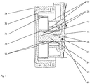
- FIG. 4 shows a sectional view of a wheel arrangement 64 according to the invention.
- the axis 14 is arranged centrally within the wheel arrangement 64.
- this forms a fixing element 22 which extends the axis 14 all around radially outwards.
- Axis 14 and fixing element 22 are integrally formed.
- the fixing element 22 forms a notch on the end face 68 which faces away from the shaft 24.
- the end face of the fixing element 22 lies completely against the nozzle body 12, without a cavity or a gap resulting between the fixing element 22 and the nozzle body 12.
- the fixing element 22 is encircled by the nozzle body 12 at its outer edges. This results in a complete positive connection between the fixing element 22 and the nozzle body 12.
- the positive connection between the fixing element 22 and the nozzle body 12 prevents any rotational or translational movement between the axis 14 and the nozzle body 12.
- the nozzle body 12 forms two collar elements 32, which are aligned approximately parallel to the shaft 24.
- the inner collar element 32 is at a smaller distance from the shaft 24 than the outer collar element 32, the outer collar element 32 being the inner collar element 32 encloses.
- Both collar elements 32 protrude from the nozzle body 12 in the direction of the wheel element 16.
- the length of the collar elements 32 corresponds approximately to half of the total shaft length 24.
- a cavity is formed between the two collar elements 32, which is open in the direction of the wheel element 16.
- the axis 14 forms a connecting section 26 approximately over the entire axis shaft length 24.
- this connecting section 26 of the axis 14 two circumferential grooves 28 are arranged at a distance from one another.
- a sleeve 70 arranged on the wheel element 16 comprises the connecting section 26 of the axle 14.
- This sleeve 70 is made in one piece with the wheel element 16.
- locking elements 30 are arranged which engage in the grooves 28 on the shaft 24. This latching connection between the sleeve 70 of the wheel element 16 and the axis 14 prevents translatory movement of the wheel element 16 in the axial direction. A rotational movement of the wheel element 16 with respect to the axis 14 is largely unimpeded.
- the wheel element 16 is composed of a wheel base 72 and a tread element 74.
- the tread element 74 surrounds the wheel base 72 on its outer circumferential surface and is in direct contact with the floor surface being traveled on in the cleaning operation.
- the tread element 74 and the wheel base 72 are positively connected to one another, the tread element 74 being made of a flexible plastic and the wheel base 72 being formed from a solid plastic material.
- the wheel base 72 forms a cavity, which is open in the assembled state of the wheel element 16 in the direction of the nozzle body 12.
- the wheel base 72 is rotationally symmetrical and forms a sleeve 70 in its central region. This sleeve 70 is surrounded by a collar element 76, the collar element 76 having approximately only half the length of the sleeve 70.
- the collar element 76 is made in one piece with the wheel base 72 and has an approximately circular base.
- the collar element 76 protects the connection point between the wheel element 16 and the nozzle body 12, which is formed by the axis 14 and the sleeve 70, against contamination by dust and dirt particles.
Landscapes
- Engineering & Computer Science (AREA)
- Mechanical Engineering (AREA)
- Nozzles For Electric Vacuum Cleaners (AREA)
Abstract
Description
- Die Erfindung betrifft eine Bodendüse mit einer Radanordnung, wobei die Bodendüse einen Düsenkörper aufweist, wobei am Düsenkörper über eine Achse ein Radelement drehbar gelagert ist, wobei die Achse ein erstes Ende und ein zweites Ende aufweist, wobei das erste Ende der Achse lösbar mit dem Radelement verbindbar ist, wobei das zweite Ende der Achse im Düsenkörper angeordnet ist. Weiterhin betrifft die Erfindung einen Staubsauger mit einer solchen Bodendüse und ein Verfahren zur Herstellung einer solchen Bodendüse.
- Im Stand der Technik, beispielweise aus der
DE 10 2011 083 885 B4 , sind Staubsauger Bodendüsen mit Rädern bekannt. Über die Anordnung von Rädern werden die für die Bewegung der Bodendüse erforderlichen Schiebekräfte reduziert, zudem lässt sich ein schonenderer Bodenkontakt der Bodendüse gewährleisten. Die im Stand der Technik bekannten Radkonzepte für Bodendüse zeichnen sich durch ihre konstruktive Komplexität und hohen Montageaufwände aus. Zudem ist es oftmals für den Benutzer nicht möglich die Räder bei den bekannten Bodendüsen auf einfache Weise zu demontieren um diese zu reinigen. - Der Erfindung stellt sich somit die Aufgabe eine Bodendüse mit Rädern zur Verfügung zu stellen, welche einen einfachen konstruktiven Aufbau aufweist und sich bequem reinigen lässt. Erfindungsgemäß wird dieses Problem durch eine Bodendüse gemäß Anspruch 1 und durch ein Verfahren gemäß Anspruch 11 gelöst. Vorteilhafte Ausgestaltungen und Weiterbildungen der Erfindung ergeben sich aus den nachfolgenden Unteransprüchen.
- Erfindungsgemäß ist am zweiten Ende der Achse ein Fixierelement ausgebildet, wobei das Fixierelement formschlüssig mit dem Düsenkörper verbunden ist. Das Fixierelement ist dabei einstückig mit der Achse ausgeführt. Das Fixierelement erweitert die Achse radial umlaufend nach außen. Achse und Fixierelement sind dabei rotationssymmetrisch ausgeführt. Die Verbindung zwischen Fixierelement und Düsenkörper ist als nicht zerstörungsfrei lösbar ausgeführt. Durch das Fixierelement ist die Achse am zweiten Ende fest mit dem Düsenkörper verbunden. Die Achse ist nur zur Lagerung eines Radelementes am Düsenkörper ausgebildet. Durch die formschlüssige Verbindung zwischen Fixierelement und Düsenkörper wird die Achse gegenüber dem Düsenkörper losdrehsicher fixiert. Zudem verursacht die erfindungsgemäße Radanordnung lediglich geringe Montageaufwände.
- Dabei ist es bevorzugt, dass die Achse einen Achsenschaft aufweist, wobei sich der Achsenschaft vom ersten Ende bis zum zweiten Ende der Achse erstreckt, wobei der Achsenschaft einen Durchmesser zwischen 5 und 10 Millimetern aufweist und in einer besonders bevorzugten Ausführungsform einen Durchmesser zwischen 7 und 9 Millimetern aufweist. Der Achsenschaft weist eine kreisförmige Grundschnittsfläche auf, wobei die Grundschnittsfläche konstant über den gesamten Verlauf des Achsenschaftes ausgeführt ist. In einer bevorzugten Ausführungsform weist der Achsenschaft eine Länge zwischen 20 und 50 Millimetern auf. Ein Achsenschaft im beanspruchten Durchmesser ist geeignet, die im Reinigungsbetrieb an der Radanordnung auftretenden Kräfte aufzunehmen ohne dass es zu Beschädigungen oder Funktionsverlusten der Radanordnung kommt.
- In einer Ausführungsform ist es bevorzugt, dass das Fixierelement gegenüber dem Achsenschaft radial nach außen erweitert ist und einen Durchmesser zwischen 15 und 30 Millimetern aufweist und in einer besonders bevorzugten Ausführungsform einen Durchmesser zwischen 15 und 25 Millimetern aufweist. Das Fixierelement weist eine kreisförmige Grundfläche auf. Die Ausführung des Fixierelementes in dem beanspruchten Durchmesser ermöglicht eine ausreichende formschlüssige Verbindung zwischen dem Düsenkörper und dem Fixierelementes während der Spritzgusses des Düsenkörpers.
- Bevorzugt ist, dass die Achse am ersten Ende einen Verbindungsabschnitt zum Verbinden mit dem Radelement ausbildet, wobei der Verbindungsabschnitt eine Länge zwischen 10 und 20 Millimetern aufweist. Der Verbindungsabschnitt erstreckt sich ausgehend vom ersten Ende der Achse in Richtung des zweiten Endes der Achse in einer Länge zwischen 10 und 20 Millimetern über den Achsenschaft. Der Verbindungsabschnitt wird dabei vollumfänglich vom Achsenschaft ausgebildet. Diese Ausführung des Verbindungsabschnittes gewährleistet zum einen ein einfache Montage des Radelementes auf der Achse und zum anderen eine sichere Arretierung des Radelementes auf der Achse während des Reinigungsbetriebes.
- Dabei ist es bevorzugt, dass die Achse am Verbindungsabschnitt eine umlaufende Nut aufweist. In einer bevorzugten Ausführungsform weist die Nut dabei eine Tiefe von 1 bis 3 Millimetern auf. In einer alternativen Ausführungsform ist es denkbar, mehrere Nuten beabstandet voneinander auf der Achse am Verbindungsabschnitt anzuordnen.
- Es ist bevorzugt, dass das Radelement ein Rastelement aufweist, wobei das Rastelement in die Nut am Verbindungsabschnitt der Achse eingreift, wenn das Radelement mit dem ersten Ende der Achse verbunden ist. Das Rastelement am Radelement ist dabei so ausgeführt, dass es vollumfänglich in die Nut am Verbindungsabschnitt der Achse eingreift. In einer alternativen Ausführungsform wäre es aber auch denkbar, dass das Rastelement nur in Teilsegmente der Nut am Verbindungsabschnitt der Achse eingreift. In einer weiteren alternativen Ausführungsform ist es denkbar mehrere Rastelemente beabstandet voneinander am Radelement anzuordnen.
- Weiterhin ist es bevorzugt, dass das Radelement einen Durchmesser zwischen 20 und 80 Millimetern aufweist. Ein Radelement im beanspruchten Durchmesser gewährleistet ein gutes Fahrverhalten der Bodendüse im Reinigungsbetrieb.
- In einer Ausführungsform ist es bevorzugt, dass der Düsenkörper ein Kragenelement ausbildet, wobei das Kragenelement die Achse abschnittsweise umschließt.
- Darüber hinaus wird auch ein Verfahren zur Herstellung einer erfindungsgemäßen Bodendüse vorgestellt, wobei das Verfahren die folgenden Schritte aufweist:
- Einlegen der Achse in ein Spritzgusswerkzeug des Düsenkörpers;
- Spritzgießen des Düsenkörpers der Bodendüse im Spritzgusswerkzeug, wobei das Fixierelement der Achse formschlüssig vom Düsenkörper umschlossen wird.
- Gemäß einer Ausführungsform des Verfahrens weist dieses den Schritt des Schmiedens der Achse auf.
- Ein Ausführungsbeispiel der Erfindung ist in den Zeichnungen rein schematisch dargestellt und wird nachfolgend näher beschrieben. Es zeigen:
- Figur 1
- Perspektivische Darstellung eines Staubsaugers mit Bodendüse;
- Figur 2
- Perspektivische Darstellung einer Bodendüse;
- Figur 3
- Perspektivische Darstellung einer Bodendüse;
- Figur 4
- Schnittansicht einer Radanordnung.
-
Figur 1 zeigt die perspektivische Ansicht eines Staubsaugers 34 mit einer an den Staubsauger 34 angeschlossenen Bodendüse 10. Bei dem dargestellten Staubsauger 34 handelt es sich um einen sogenannten Kanister-Staubsauger. Die Bodendüse 10 ist hier über ihr Kopplungselement 36 mit einem vorzugsweise teleskopierbar ausgestalteten Saugrohr 38 verbunden. Weiterhin weist die Bodendüse 10 bei diesem gezeigten Ausführungsbeispiel einen eigenen vom Staubsauger unabhängigen Düsenkörper 12 auf. Das teleskopierbare Saugrohr 38 geht in einen Handgriff 40 über, an dem ein Saugschlauch 42 angeschlossen ist, der mit dem Staubsaugergehäuse verbunden ist. Über ein elektrisches Anschlusskabel 44 wird ein in dem Staubsaugergehäuse integriertes Gebläse (nicht dargestellt inFigur 1 ) des Staubsaugers 34 mit Strom betrieben, um einen Unterdruck zu erzeugen. Mittels dieses Unterdruckes wird Schmutz und Dreck von der zu reinigenden Bodenfläche durch einen Luftstrom über den Saugmund der Bodendüse 10 aufgenommen und über das Saugrohr 38 und den Saugschlauch 42 in das Gehäuse des Staubsaugers 34 abtransportiert. In diesem Gehäuse vorgesehen ist ein Abscheidesystem 46, welches im Ausführungsbeispiel als Staubbeutel ausgebildet ist. Dieses Abscheidesystem 46 befindet sich in einem durch die Gehäuseteile 48 des Staubsaugers 34 gebildeten Staubraum 50. Dieser Staubraum 50 ist durch einen Klappmechanismus zwischen den Staubsaugergehäuseteilen 48 zugänglich und geöffnet dargestellt, sodass das Abscheidesystem 46 sichtbar und entnehmbar ist. Für den Betrieb des Staubsaugers 34 wird der Staubraum 50 geschlossen und ein Unterdruck erzeugt. Der durch den Unterdruck erzeugte Luftstrom wird in dem Abscheidesystem 46 von Schmutz und Dreck befreit und über ein Abluftgitter aus dem Staubsauger 34 herausgeleitet. Zum Ein- und Ausschalten des Staubsaugers 34 weist dieser eine Trittschaltung 52 auf. Diese Trittschaltung 52 umfasst Schalter, die ausreichend groß sind, damit ein Benutzer diese mit dem Fuß betätigen kann. Die Trittschaltung 52 weist üblicherweise auch einen Schalter zur Betätigung der im Staubsaugergehäuse integrierten Wickelautomatik (nicht dargestellt inFigur 1 ) für das Anschlusskabel 44 auf. An dem Handgriff 40 befindet sich zudem eine Handschaltung mit welcher Funktionen des Staubsaugers 34 aktiviert werden können. Außerdem kann der Staubsauger 34 über die Handschaltung ein- und ausgeschaltet werden und es können Leistungsstufen des Gebläses ausgewählt werden. Ein Benutzer des Staubsaugers 34 kann diesen an dem Handgriff 40 ergreifen und so die Bodendüse 10 mittels Schub- und Zugbewegungen vor- und zurückschieben, um die Bodenfläche zu reinigen. Hierbei gleitet die Bodendüse 10 über die zu reinigende Bodenfläche. Besonders bei langflorigen Teppichen gleitet die Unterseite der Bodendüse 10 über die Bodenfläche, während die Unterseite bei Hartböden beabstandet, gegebenenfalls durch Abstandsborsten, über diese Bodenflächen hinweg schwebt. Im dargestellten Ausführungsbeispiel weist die Bodendüse 10 Räder 16 auf, welche eine einfache Handhabung beim Vor- und Zurückschieben der Bodendüse 10 sicherstellen. -
Figur 2 zeigt die perspektivische Ansicht eines Düsenkörpers 12 mit demontierten Radelementen. Bei dem abgebildeten Düsenkörper 12 handelt es sich um ein Düsenkörperelement 12, welches in Kombination mit weiteren nicht dargestellten Düsenkörperelementen eine vollständige Bodendüse 10 bildet. Das Düsenkörperelement 12 bildet auf seiner Oberseite einen Kanalabschnitt 56 aus, in welchem ein Schlauchelement 58 der Bodendüse 10 gelagert ist. Das Schlauchelement 58 verbindet fluiddicht ein Saugkanalabschnittselement 60 mit einem Gelenkelement 62 der Bodendüse 10. Sowohl der Saugkanalabschnittselement 60 als auch das Gelenkelement 62 sind dabei im Düsenkörper 12 gelagert. An dem Ende des Gelenkelementes 62, welches dem Schlauchelement 58 gegenüberliegt, ist ein Kupplungselement 36 angeordnet. Über das Kupplungselement 36 ist die Bodendüse 10 mit einem Saugrohr 38 verbindbar. - An einer Seitenfläche des Düsenkörpers 12, welche im Reinigungsbetrieb der Bodendüse 10 annähernd orthogonal zu der zu reinigenden Fläche ausgerichtet, ist die Radanordnung 64 der Bodendüse 10 angeordnet. Die Radanordnung 64 wird dabei am Düsenkörper 12 durch ein Radhaus 66 eingefasst, welches durch den Düsenkörper 12 ausgebildet wird. Annähernd mittig zentriert in Bezug auf die Radanordnung 64 ist dabei die Achse 14 angeordnet. Die Achse 12 wird dabei mit ihrem ersten Ende 18 vom Düsenkörper 12 aufgenommen und steht mit ihrem zweiten Ende 20 von dem Düsenkörper 12 hervor. Die Achse 14 ist dabei im Reinigungsbetrieb der Bodendüse 10 annährend parallel zu der zu reinigenden Bodenfläche ausgerichtet. Am zweiten Ende 20 der Achse 14 sind in der Achse 14 zwei umlaufende voneinander beabstandete Nuten 28 angeordnet. Die Achse 14 wird durch zwei Kragenelemente 32, welche durch den Düsenkörper 12 an der Radanordnung 64 gebildet werden, eingefasst. Diese Kragenelemente 32 stehen dabei weniger weit vom Düsenkörper 12 hervor als die Achse. Das innere Kragenelement 32, welches die Achse 14 unmittelbar umschließt, weißt eine annähernd runde Grundfläche auf. Das äußere Kragenelement 32, welches sowohl die Achse 14 als auch das innere Kragenelement 32 umschließt, weist eine annähernd ovale Grundfläche auf. Beide Kragenelemente 32 verhindern im Reinigungsbetrieb der Bodendüse 10 eine Verschmutzung der Radanordnung 64, insbesondere der Achse 14, durch Staub- und Schmutzpartikel.
-
Figur 3 zeigt die perspektivische Ansicht eines Düsenkörpers 12 mit montierten Radelementen 16. An einer Seitenfläche des Düsenkörpers 12, welche im Reinigungsbetrieb der Bodendüse 10 annähernd orthogonal zu der Bodenfläche ausgerichtet ist, ist ein Radhaus 66 am Düsenkörper 12 angeordnet. Das Radhaus 66 weist eine halbkreisförmige Grundform auf und ist in Richtung der zu reinigenden Bodenfläche geöffnet. Mittig zentriert im Radhaus 66 der Bodendüse 10 ist das Radelement 16 drehbar gelagert angeordnet. Das Radelement 16 verfügt dabei über eine runde Grundform. -
Figur 4 zeigt eine Schnittansicht einer erfindungsgemäßen Radanordnung 64. Die Achse 14 ist dabei zentral innerhalb der Radanordnung 64 angeordnet. An dem zweiten Ende 20 der Achse 14 bildet diese ein Fixierelement 22 aus, welches die Achse 14 radial nach außen umlaufend erweitert. Achse 14 und Fixierelement 22 sind dabei einstückig ausgebildet. Das Fixierelement 22 bildet dabei auf der Stirnfläche 68, welche dem Achsenschaft 24 abgewandt ist, eine Einkerbung aus. Das Fixierelement 22 liegt mit seiner Stirnfläche 68 vollständig am Düsenkörper 12 an, ohne dass sich zwischen Fixierelement 22 und Düsenkörper 12 ein Hohlraum oder ein Spalt ergibt. Zusätzlich wird das Fixierelement 22 an seinen äußeren Rändern umlaufend vom Düsenkörper 12 umfasst. Hierdurch resultiert ein vollständiger Formschluss zwischen dem Fixierelement 22 und dem Düsenkörper 12. Der Formschluss zwischen Fixierelement 22 und Düsenkörper 12 verhindert jegliche Rotations- oder Translationsbewegung zwischen der Achse 14 und dem Düsenkörper 12. - Am Rand des Fixierelements 22 bildet der Düsenkörper 12 zwei Kragenelemente 32 aus, welche annähernd parallel zum Achsenschaft 24 ausgerichtet sind. Das innere Kragenelement 32 weist dabei einen geringeren Abstand zum Achsenschaft 24 auf als das äußere Kragenelement 32, wobei das äußere Kragenelement 32 das innere Kragenelement 32 umschließt. Beide Kragenelemente 32 stehen dabei vom Düsenkörper 12 in Richtung des Radelementes 16 ab. Die Länge der Kragenelemente 32 entspricht annähernd der Hälfte der gesamten Achsenschaftlänge 24. Zwischen den beiden Kragenelementen 32 bildet sich ein Hohlraum aus, welcher in Richtung des Radelementes 16 geöffnet ist.
- Die Achse 14 bildet ausgehend vom ersten Ende 18 annähernd über die gesamte Achsenschaftlänge 24 einen Verbindungsabschnitt 26 aus. In diesem Verbindungsabschnitt 26 der Achse 14 sind zwei umlaufende Nuten 28 beabstandet voneinander angeordnet. Im aufgesetzten Zustand des Radelementes 16 umfasst eine am Radelement 16 angeordnete Hülse 70 den Verbindungsabschnitt 26 der Achse 14. Diese Hülse 70 ist einstückig mit dem Radelement 16 ausgeführt. Auf der Hülseninnenseite sind Rastelemente 30 angeordnet, welche in die Nuten 28 auf dem Achsenschaft 24 eingreifen. Durch diese Rastverbindung zwischen der Hülse 70 des Radelementes 16 und der Achse 14 wird eine translatorische Bewegung des Radelementes 16 in axiale Richtung verhindert. Eine Rotationsbewegung des Radelementes 16 gegenüber der Achse 14 ist weitestgehend ungehindert möglich.
- Das Radelement 16 setzt sich aus einem Radgrundkörper 72 und einem Laufflächenelement 74 zusammen. Das Laufflächenelement 74 umschließt den Radgrundkörper 72 an seiner äußeren Umfangsfläche und befindet sich im Reinigungsbetrieb im direkten Kontakt mit der befahrenen Bodenfläche. Das Laufflächenelement 74 und der Radgrundkörper 72 sind formschlüssig miteinander verbunden, wobei das Laufflächenelement 74 aus einem weichelastischen Kunststoff besteht und der Radgrundkörper 72 aus einem festen Kunststoffmaterial gebildet wird. Der Radgrundkörper 72 bildet einen Hohlraum aus, welcher im montierten Zustand des Radelementes 16 in Richtung des Düsenkörpers 12 geöffnet ist. Der Radgrundkörper 72 ist rotationssymmetrisch ausgeführt und bildet in seinen mittleren Bereich eine Hülse 70 aus. Diese Hülse 70 ist von einem Kragenelement 76 umfasst, wobei das Kragenelement 76 in etwa nur die Hälfte der Länge der Hülse 70 aufweist. Das Kragenelement 76 ist einstückig mit dem Radgrundkörper 72 ausgeführt und weist eine annähernd kreisförmige Grundfläche auf. Durch das Kragenelement 76 wird die Verbindungstelle zwischen Radelement 16 und Düsenkörper 12, welche durch die Achse 14 und die Hülse 70 gebildet wird, vor Verschmutzung durch Staub- und Schmutzpartikel geschützt.
-
- 10
- Bodendüse
- 12
- Düsenkörper
- 14
- Achse
- 16
- Radelement / Räder
- 18
- erstes Ende der Achse
- 20
- zweites Ende der Achse
- 22
- Fixierelement
- 24
- Achsenschaft
- 26
- Verbindungsabschnitt
- 28
- Nut
- 30
- Rastelement
- 32
- Kragenelement
- 34
- Staubsauger
- 36
- Kopplungselement
- 38
- Saugrohr
- 40
- Handgriff
- 42
- Saugschlauch
- 44
- Anschlusskabel
- 46
- Abscheidesystem
- 48
- Gehäuseteile
- 50
- Staubraum
- 52
- Trittschaltung
- 56
- Anschlusskabel
- 58
- Schlauchelement
- 60
- Saugkanalabschnittselement
- 62
- Gelenkelement
- 64
- Radanordnung
- 66
- Radhaus
- 68
- Stirnfläche Achse
- 70
- Hülse
- 72
- Radgrundkörper
- 74
- Laufflächenelement
- 76
- Kragenelement
Claims (11)
- Bodendüse (10) mit einer Radanordnung, wobei die Bodendüse (10) einen Düsenkörper (12) aufweist, wobei am Düsenkörper (12) über eine Achse (14) ein Radelement (16) drehbar gelagert ist, wobei die Achse (14) ein erstes Ende (18) und ein zweites Ende (20) aufweist, wobei das erste Ende (18) der Achse (14) lösbar mit dem Radelement (16) verbindbar ist, wobei das zweite Ende (20) der Achse (14) im Düsenkörper (12) angeordnet ist,
dadurch gekennzeichnet,
dass am zweiten Ende (20) der Achse (14) ein Fixierelement (22) ausgebildet ist, wobei das Fixierelement (22) formschlüssig mit dem Düsenkörper (12) verbunden ist. - Bodendüse (10) nach Anspruch 1,
dadurch gekennzeichnet,
dass die Achse (14) einen Achsenschaft (24) aufweist, wobei sich der Achsenschaft (24) vom ersten Ende (18) bis zum zweiten Ende (20) der Achse (14) erstreckt, wobei der Achsenschaft (24) einen Durchmesser zwischen 5 und 10 Millimetern aufweist und in einer besonders bevorzugten Ausführungsform einen Durchmesser zwischen 7 und 9 Millimetern aufweist. - Bodendüse (10) nach einem der vorgehenden Ansprüche,
dadurch gekennzeichnet,
dass das Fixierelement (22) gegenüber dem Achsenschaft (24) radial nach außen erweitert ist und einen Durchmesser zwischen 15 und 30 Millimetern aufweist und in einer besonders bevorzugten Ausführungsform einen Durchmesser zwischen 15 und 25 Millimetern aufweist. - Bodendüse (10) nach einem der vorgehenden Ansprüche,
dadurch gekennzeichnet,
dass die Achse (14) am ersten Ende (18) einen Verbindungsabschnitt (26) zum Verbinden mit dem Radelement (16) ausbildet, wobei der Verbindungsabschnitt (26) eine Länge zwischen 10 und 20 Millimetern aufweist. - Bodendüse (10) nach einem der vorgehenden Ansprüche,
dadurch gekennzeichnet,
dass die Achse (14) am Verbindungsabschnitt (26)eine umlaufende Nut (28) aufweist. - Bodendüse (10) nach einem der vorgehenden Ansprüche,
dadurch gekennzeichnet,
dass das Radelement (16) ein Rastelement (30) aufweist, wobei das Rastelement (30) in die Nut (28) am Verbindungsabschnitt (26) der Achse (14) eingreift, wenn das Radelement (16) mit dem ersten Ende (18) der Achse (14) verbunden ist. - Bodendüse (10) nach einem der vorgehenden Ansprüche,
dadurch gekennzeichnet,
dass das Radelement (16) einen Durchmesser zwischen 20 und 80 Millimetern aufweist. - Bodendüse (10) nach einem der vorgehenden Ansprüche,
dadurch gekennzeichnet,
dass der Düsenkörper (12) ein Kragenelement (32) ausbildet, wobei das Kragenelement (32) die Achse (14) abschnittsweise umschließt. - Staubsauger (34) mit einer Bodendüse (10) nach einem der vorgehenden Ansprüche.
- Verfahren zum Herstellen einer Bodendüse (10) gemäß einem der vorgehenden Ansprüche, wobei das Verfahren die folgenden Schritte aufweist:Einlegen der Achse (14) in ein Spritzgusswerkzeug des Düsenkörpers (12);Spritzgießen des Düsenkörpers (12) der Bodendüse (10) im Spritzgusswerkzeug, wobei das Fixierelement (22) der Achse (14) formschlüssig vom Düsenkörper (12) umschlossen wird.
- Verfahren gemäß Anspruch 10, mit einem Schritt des Schmiedens der Achse (14).
Applications Claiming Priority (1)
| Application Number | Priority Date | Filing Date | Title |
|---|---|---|---|
| DE102018122352.8A DE102018122352A1 (de) | 2018-09-13 | 2018-09-13 | Bodendüse mit einer Radanordnung, Staubsauger mit einer Bodendüse und Verfahren zur Herstellung einer Bodendüse |
Publications (2)
| Publication Number | Publication Date |
|---|---|
| EP3622870A1 true EP3622870A1 (de) | 2020-03-18 |
| EP3622870B1 EP3622870B1 (de) | 2022-07-20 |
Family
ID=67810424
Family Applications (1)
| Application Number | Title | Priority Date | Filing Date |
|---|---|---|---|
| EP19194530.2A Active EP3622870B1 (de) | 2018-09-13 | 2019-08-30 | Bodendüse mit einer radanordnung, staubsauger mit einer bodendüse und verfahren zur herstellung einer bodendüse |
Country Status (2)
| Country | Link |
|---|---|
| EP (1) | EP3622870B1 (de) |
| DE (1) | DE102018122352A1 (de) |
Citations (4)
| Publication number | Priority date | Publication date | Assignee | Title |
|---|---|---|---|---|
| US2073347A (en) * | 1936-10-21 | 1937-03-09 | Quadrex Corp | Collapsible wheel for vacuum cleaners |
| EP0688528A1 (de) * | 1994-06-21 | 1995-12-27 | AEG Hausgeräte GmbH | Staubsaugermundstück mit Stützrädern |
| DE102011083885B4 (de) | 2011-09-30 | 2013-05-16 | BSH Bosch und Siemens Hausgeräte GmbH | Radanordnung für eine Bodendüse eines Staubsaugers |
| US20160113458A1 (en) * | 2014-10-27 | 2016-04-28 | Conet Industries, Inc. | Cleaning nozzle assembly |
Family Cites Families (5)
| Publication number | Priority date | Publication date | Assignee | Title |
|---|---|---|---|---|
| JP2004129859A (ja) * | 2002-10-10 | 2004-04-30 | Toshiba Tec Corp | 電気掃除機 |
| DE102007011754B3 (de) * | 2007-03-10 | 2008-04-24 | Wessel-Werk Gmbh | Bodendüse für Staubsauger |
| US8444228B2 (en) * | 2010-09-29 | 2013-05-21 | Cascade Engineering, Inc. | Wheel assembly for trash/recycling cart |
| DE102011081838A1 (de) * | 2010-11-05 | 2012-05-10 | BSH Bosch und Siemens Hausgeräte GmbH | Saugdüse, Verfahren zu deren Herstellung und damit ausgestatteter Staubsauger |
| DE102010043515B4 (de) * | 2010-11-05 | 2014-10-16 | BSH Bosch und Siemens Hausgeräte GmbH | Saugdüsenanordnung und Bodenstaubsauger |
-
2018
- 2018-09-13 DE DE102018122352.8A patent/DE102018122352A1/de not_active Withdrawn
-
2019
- 2019-08-30 EP EP19194530.2A patent/EP3622870B1/de active Active
Patent Citations (4)
| Publication number | Priority date | Publication date | Assignee | Title |
|---|---|---|---|---|
| US2073347A (en) * | 1936-10-21 | 1937-03-09 | Quadrex Corp | Collapsible wheel for vacuum cleaners |
| EP0688528A1 (de) * | 1994-06-21 | 1995-12-27 | AEG Hausgeräte GmbH | Staubsaugermundstück mit Stützrädern |
| DE102011083885B4 (de) | 2011-09-30 | 2013-05-16 | BSH Bosch und Siemens Hausgeräte GmbH | Radanordnung für eine Bodendüse eines Staubsaugers |
| US20160113458A1 (en) * | 2014-10-27 | 2016-04-28 | Conet Industries, Inc. | Cleaning nozzle assembly |
Also Published As
| Publication number | Publication date |
|---|---|
| DE102018122352A1 (de) | 2020-03-19 |
| EP3622870B1 (de) | 2022-07-20 |
Similar Documents
| Publication | Publication Date | Title |
|---|---|---|
| DE10126354C2 (de) | Angetriebene Bürstenanordnung für Staubsauger | |
| EP2979602B1 (de) | Rückspülbarer luftfilter | |
| DE102017127086A1 (de) | Regenerierbarer Luftfilter | |
| DE102009013475B4 (de) | Mittels einer Laufrolle verfahrbarer Gegenstand | |
| EP3789099A1 (de) | Entnahmesystem sowie entnahmehilfe für ein abscheideelement | |
| EP3622870B1 (de) | Bodendüse mit einer radanordnung, staubsauger mit einer bodendüse und verfahren zur herstellung einer bodendüse | |
| WO2007025924A1 (de) | Staubsaugerbeutel mit kunststoffflansch | |
| DE102021125126A1 (de) | Gebläse und Stutzen | |
| EP3984429A1 (de) | Staubsauger und verfahren zum betrieb eines staubsaugers | |
| EP2815686B1 (de) | Filterbaugruppe für einen Staubsauger und Staubsauger | |
| EP4179944B1 (de) | Filtereinheit für den ansaugstutzen im schmutzwassertank einer bodenreinigungsmaschine | |
| EP3616581B1 (de) | Staubsauger | |
| EP3440973B1 (de) | Bodendüse für staubsauger und staubsauger | |
| EP4133983B1 (de) | Staubbeutel | |
| DE102019112667A1 (de) | Saugroboter zur autonomen Reinigung von Bodenflächen | |
| EP4133984B1 (de) | Staubbeutelentnahmemodul und staubsauger | |
| DE102021211191B4 (de) | Staubsauger mit Seitenbürste | |
| EP1924187B1 (de) | Staubsaugerbodendüse mit anzeige | |
| EP1924182B1 (de) | Staubsaugerdüse | |
| EP1928287A1 (de) | Borstenleiste | |
| EP2965679B1 (de) | Saugschlauch für einen staubsauger und staubsauger mit einem solchen saugschlauch | |
| EP3298944B1 (de) | Bodendüse für staubsauger und staubsauger | |
| DE102018119176A1 (de) | Bodendüse für einen Staubsauger | |
| DE102021100072A1 (de) | Staubsauger | |
| DE102015100873A1 (de) | Saugdüse |
Legal Events
| Date | Code | Title | Description |
|---|---|---|---|
| PUAI | Public reference made under article 153(3) epc to a published international application that has entered the european phase |
Free format text: ORIGINAL CODE: 0009012 |
|
| STAA | Information on the status of an ep patent application or granted ep patent |
Free format text: STATUS: REQUEST FOR EXAMINATION WAS MADE |
|
| 17P | Request for examination filed |
Effective date: 20200212 |
|
| AK | Designated contracting states |
Kind code of ref document: A1 Designated state(s): AL AT BE BG CH CY CZ DE DK EE ES FI FR GB GR HR HU IE IS IT LI LT LU LV MC MK MT NL NO PL PT RO RS SE SI SK SM TR |
|
| AX | Request for extension of the european patent |
Extension state: BA ME |
|
| GRAP | Despatch of communication of intention to grant a patent |
Free format text: ORIGINAL CODE: EPIDOSNIGR1 |
|
| STAA | Information on the status of an ep patent application or granted ep patent |
Free format text: STATUS: GRANT OF PATENT IS INTENDED |
|
| INTG | Intention to grant announced |
Effective date: 20220413 |
|
| GRAS | Grant fee paid |
Free format text: ORIGINAL CODE: EPIDOSNIGR3 |
|
| GRAA | (expected) grant |
Free format text: ORIGINAL CODE: 0009210 |
|
| STAA | Information on the status of an ep patent application or granted ep patent |
Free format text: STATUS: THE PATENT HAS BEEN GRANTED |
|
| AK | Designated contracting states |
Kind code of ref document: B1 Designated state(s): AL AT BE BG CH CY CZ DE DK EE ES FI FR GB GR HR HU IE IS IT LI LT LU LV MC MK MT NL NO PL PT RO RS SE SI SK SM TR |
|
| REG | Reference to a national code |
Ref country code: CH Ref legal event code: EP |
|
| REG | Reference to a national code |
Ref country code: DE Ref legal event code: R084 Ref document number: 502019004998 Country of ref document: DE Ref country code: DE Ref legal event code: R096 Ref document number: 502019004998 Country of ref document: DE |
|
| REG | Reference to a national code |
Ref country code: AT Ref legal event code: REF Ref document number: 1505007 Country of ref document: AT Kind code of ref document: T Effective date: 20220815 |
|
| REG | Reference to a national code |
Ref country code: IE Ref legal event code: FG4D Free format text: LANGUAGE OF EP DOCUMENT: GERMAN Ref country code: GB Ref legal event code: 746 Effective date: 20220805 |
|
| REG | Reference to a national code |
Ref country code: LT Ref legal event code: MG9D |
|
| REG | Reference to a national code |
Ref country code: NL Ref legal event code: MP Effective date: 20220720 |
|
| PG25 | Lapsed in a contracting state [announced via postgrant information from national office to epo] |
Ref country code: SE Free format text: LAPSE BECAUSE OF FAILURE TO SUBMIT A TRANSLATION OF THE DESCRIPTION OR TO PAY THE FEE WITHIN THE PRESCRIBED TIME-LIMIT Effective date: 20220720 Ref country code: RS Free format text: LAPSE BECAUSE OF FAILURE TO SUBMIT A TRANSLATION OF THE DESCRIPTION OR TO PAY THE FEE WITHIN THE PRESCRIBED TIME-LIMIT Effective date: 20220720 Ref country code: PT Free format text: LAPSE BECAUSE OF FAILURE TO SUBMIT A TRANSLATION OF THE DESCRIPTION OR TO PAY THE FEE WITHIN THE PRESCRIBED TIME-LIMIT Effective date: 20221121 Ref country code: NO Free format text: LAPSE BECAUSE OF FAILURE TO SUBMIT A TRANSLATION OF THE DESCRIPTION OR TO PAY THE FEE WITHIN THE PRESCRIBED TIME-LIMIT Effective date: 20221020 Ref country code: NL Free format text: LAPSE BECAUSE OF FAILURE TO SUBMIT A TRANSLATION OF THE DESCRIPTION OR TO PAY THE FEE WITHIN THE PRESCRIBED TIME-LIMIT Effective date: 20220720 Ref country code: LV Free format text: LAPSE BECAUSE OF FAILURE TO SUBMIT A TRANSLATION OF THE DESCRIPTION OR TO PAY THE FEE WITHIN THE PRESCRIBED TIME-LIMIT Effective date: 20220720 Ref country code: LT Free format text: LAPSE BECAUSE OF FAILURE TO SUBMIT A TRANSLATION OF THE DESCRIPTION OR TO PAY THE FEE WITHIN THE PRESCRIBED TIME-LIMIT Effective date: 20220720 Ref country code: FI Free format text: LAPSE BECAUSE OF FAILURE TO SUBMIT A TRANSLATION OF THE DESCRIPTION OR TO PAY THE FEE WITHIN THE PRESCRIBED TIME-LIMIT Effective date: 20220720 Ref country code: ES Free format text: LAPSE BECAUSE OF FAILURE TO SUBMIT A TRANSLATION OF THE DESCRIPTION OR TO PAY THE FEE WITHIN THE PRESCRIBED TIME-LIMIT Effective date: 20220720 |
|
| PG25 | Lapsed in a contracting state [announced via postgrant information from national office to epo] |
Ref country code: PL Free format text: LAPSE BECAUSE OF FAILURE TO SUBMIT A TRANSLATION OF THE DESCRIPTION OR TO PAY THE FEE WITHIN THE PRESCRIBED TIME-LIMIT Effective date: 20220720 Ref country code: IS Free format text: LAPSE BECAUSE OF FAILURE TO SUBMIT A TRANSLATION OF THE DESCRIPTION OR TO PAY THE FEE WITHIN THE PRESCRIBED TIME-LIMIT Effective date: 20221120 Ref country code: HR Free format text: LAPSE BECAUSE OF FAILURE TO SUBMIT A TRANSLATION OF THE DESCRIPTION OR TO PAY THE FEE WITHIN THE PRESCRIBED TIME-LIMIT Effective date: 20220720 Ref country code: GR Free format text: LAPSE BECAUSE OF FAILURE TO SUBMIT A TRANSLATION OF THE DESCRIPTION OR TO PAY THE FEE WITHIN THE PRESCRIBED TIME-LIMIT Effective date: 20221021 |
|
| REG | Reference to a national code |
Ref country code: CH Ref legal event code: PL |
|
| REG | Reference to a national code |
Ref country code: DE Ref legal event code: R097 Ref document number: 502019004998 Country of ref document: DE |
|
| PG25 | Lapsed in a contracting state [announced via postgrant information from national office to epo] |
Ref country code: SM Free format text: LAPSE BECAUSE OF FAILURE TO SUBMIT A TRANSLATION OF THE DESCRIPTION OR TO PAY THE FEE WITHIN THE PRESCRIBED TIME-LIMIT Effective date: 20220720 Ref country code: RO Free format text: LAPSE BECAUSE OF FAILURE TO SUBMIT A TRANSLATION OF THE DESCRIPTION OR TO PAY THE FEE WITHIN THE PRESCRIBED TIME-LIMIT Effective date: 20220720 Ref country code: MC Free format text: LAPSE BECAUSE OF FAILURE TO SUBMIT A TRANSLATION OF THE DESCRIPTION OR TO PAY THE FEE WITHIN THE PRESCRIBED TIME-LIMIT Effective date: 20220720 Ref country code: LU Free format text: LAPSE BECAUSE OF NON-PAYMENT OF DUE FEES Effective date: 20220830 Ref country code: LI Free format text: LAPSE BECAUSE OF NON-PAYMENT OF DUE FEES Effective date: 20220831 Ref country code: DK Free format text: LAPSE BECAUSE OF FAILURE TO SUBMIT A TRANSLATION OF THE DESCRIPTION OR TO PAY THE FEE WITHIN THE PRESCRIBED TIME-LIMIT Effective date: 20220720 Ref country code: CZ Free format text: LAPSE BECAUSE OF FAILURE TO SUBMIT A TRANSLATION OF THE DESCRIPTION OR TO PAY THE FEE WITHIN THE PRESCRIBED TIME-LIMIT Effective date: 20220720 Ref country code: CH Free format text: LAPSE BECAUSE OF NON-PAYMENT OF DUE FEES Effective date: 20220831 |
|
| REG | Reference to a national code |
Ref country code: BE Ref legal event code: MM Effective date: 20220831 |
|
| PLBE | No opposition filed within time limit |
Free format text: ORIGINAL CODE: 0009261 |
|
| STAA | Information on the status of an ep patent application or granted ep patent |
Free format text: STATUS: NO OPPOSITION FILED WITHIN TIME LIMIT |
|
| PG25 | Lapsed in a contracting state [announced via postgrant information from national office to epo] |
Ref country code: SK Free format text: LAPSE BECAUSE OF FAILURE TO SUBMIT A TRANSLATION OF THE DESCRIPTION OR TO PAY THE FEE WITHIN THE PRESCRIBED TIME-LIMIT Effective date: 20220720 Ref country code: EE Free format text: LAPSE BECAUSE OF FAILURE TO SUBMIT A TRANSLATION OF THE DESCRIPTION OR TO PAY THE FEE WITHIN THE PRESCRIBED TIME-LIMIT Effective date: 20220720 |
|
| 26N | No opposition filed |
Effective date: 20230421 |
|
| PG25 | Lapsed in a contracting state [announced via postgrant information from national office to epo] |
Ref country code: AL Free format text: LAPSE BECAUSE OF FAILURE TO SUBMIT A TRANSLATION OF THE DESCRIPTION OR TO PAY THE FEE WITHIN THE PRESCRIBED TIME-LIMIT Effective date: 20220720 |
|
| P01 | Opt-out of the competence of the unified patent court (upc) registered |
Effective date: 20230528 |
|
| PG25 | Lapsed in a contracting state [announced via postgrant information from national office to epo] |
Ref country code: IE Free format text: LAPSE BECAUSE OF NON-PAYMENT OF DUE FEES Effective date: 20220830 |
|
| PG25 | Lapsed in a contracting state [announced via postgrant information from national office to epo] |
Ref country code: SI Free format text: LAPSE BECAUSE OF FAILURE TO SUBMIT A TRANSLATION OF THE DESCRIPTION OR TO PAY THE FEE WITHIN THE PRESCRIBED TIME-LIMIT Effective date: 20220720 |
|
| PG25 | Lapsed in a contracting state [announced via postgrant information from national office to epo] |
Ref country code: BE Free format text: LAPSE BECAUSE OF NON-PAYMENT OF DUE FEES Effective date: 20220831 |
|
| PG25 | Lapsed in a contracting state [announced via postgrant information from national office to epo] |
Ref country code: HU Free format text: LAPSE BECAUSE OF FAILURE TO SUBMIT A TRANSLATION OF THE DESCRIPTION OR TO PAY THE FEE WITHIN THE PRESCRIBED TIME-LIMIT; INVALID AB INITIO Effective date: 20190830 |
|
| PG25 | Lapsed in a contracting state [announced via postgrant information from national office to epo] |
Ref country code: CY Free format text: LAPSE BECAUSE OF FAILURE TO SUBMIT A TRANSLATION OF THE DESCRIPTION OR TO PAY THE FEE WITHIN THE PRESCRIBED TIME-LIMIT Effective date: 20220720 |
|
| PG25 | Lapsed in a contracting state [announced via postgrant information from national office to epo] |
Ref country code: MK Free format text: LAPSE BECAUSE OF FAILURE TO SUBMIT A TRANSLATION OF THE DESCRIPTION OR TO PAY THE FEE WITHIN THE PRESCRIBED TIME-LIMIT Effective date: 20220720 |
|
| PG25 | Lapsed in a contracting state [announced via postgrant information from national office to epo] |
Ref country code: BG Free format text: LAPSE BECAUSE OF FAILURE TO SUBMIT A TRANSLATION OF THE DESCRIPTION OR TO PAY THE FEE WITHIN THE PRESCRIBED TIME-LIMIT Effective date: 20220720 |
|
| PG25 | Lapsed in a contracting state [announced via postgrant information from national office to epo] |
Ref country code: MT Free format text: LAPSE BECAUSE OF FAILURE TO SUBMIT A TRANSLATION OF THE DESCRIPTION OR TO PAY THE FEE WITHIN THE PRESCRIBED TIME-LIMIT Effective date: 20220720 |
|
| PGFP | Annual fee paid to national office [announced via postgrant information from national office to epo] |
Ref country code: DE Payment date: 20250831 Year of fee payment: 7 |
|
| PGFP | Annual fee paid to national office [announced via postgrant information from national office to epo] |
Ref country code: TR Payment date: 20250818 Year of fee payment: 7 Ref country code: IT Payment date: 20250825 Year of fee payment: 7 |
|
| REG | Reference to a national code |
Ref country code: AT Ref legal event code: MM01 Ref document number: 1505007 Country of ref document: AT Kind code of ref document: T Effective date: 20240830 |
|
| PGFP | Annual fee paid to national office [announced via postgrant information from national office to epo] |
Ref country code: GB Payment date: 20250826 Year of fee payment: 7 |
|
| PG25 | Lapsed in a contracting state [announced via postgrant information from national office to epo] |
Ref country code: AT Free format text: LAPSE BECAUSE OF NON-PAYMENT OF DUE FEES Effective date: 20240830 |
|
| PGFP | Annual fee paid to national office [announced via postgrant information from national office to epo] |
Ref country code: FR Payment date: 20250825 Year of fee payment: 7 |
|
| PGFP | Annual fee paid to national office [announced via postgrant information from national office to epo] |
Ref country code: AT Payment date: 20260410 Year of fee payment: 5 |