EP3621871B1 - Fluchtsystem - Google Patents
Fluchtsystem Download PDFInfo
- Publication number
- EP3621871B1 EP3621871B1 EP18724842.2A EP18724842A EP3621871B1 EP 3621871 B1 EP3621871 B1 EP 3621871B1 EP 18724842 A EP18724842 A EP 18724842A EP 3621871 B1 EP3621871 B1 EP 3621871B1
- Authority
- EP
- European Patent Office
- Prior art keywords
- platform
- passage
- rail
- escape system
- recess
- Prior art date
- Legal status (The legal status is an assumption and is not a legal conclusion. Google has not performed a legal analysis and makes no representation as to the accuracy of the status listed.)
- Active
Links
Images







Classifications
-
- B—PERFORMING OPERATIONS; TRANSPORTING
- B63—SHIPS OR OTHER WATERBORNE VESSELS; RELATED EQUIPMENT
- B63C—LAUNCHING, HAULING-OUT, OR DRY-DOCKING OF VESSELS; LIFE-SAVING IN WATER; EQUIPMENT FOR DWELLING OR WORKING UNDER WATER; MEANS FOR SALVAGING OR SEARCHING FOR UNDERWATER OBJECTS
- B63C9/00—Life-saving in water
- B63C9/22—Devices for holding or launching life-buoys, inflatable life-rafts, or other floatable life-saving equipment
-
- A—HUMAN NECESSITIES
- A62—LIFE-SAVING; FIRE-FIGHTING
- A62B—DEVICES, APPARATUS OR METHODS FOR LIFE-SAVING
- A62B1/00—Devices for lowering persons from buildings or the like
- A62B1/20—Devices for lowering persons from buildings or the like by making use of sliding-ropes, sliding-poles or chutes, e.g. hoses, pipes, sliding-grooves, sliding-sheets
-
- B—PERFORMING OPERATIONS; TRANSPORTING
- B63—SHIPS OR OTHER WATERBORNE VESSELS; RELATED EQUIPMENT
- B63B—SHIPS OR OTHER WATERBORNE VESSELS; EQUIPMENT FOR SHIPPING
- B63B27/00—Arrangement of ship-based loading or unloading equipment for cargo or passengers
- B63B27/14—Arrangement of ship-based loading or unloading equipment for cargo or passengers of ramps, gangways or outboard ladders ; Pilot lifts
- B63B27/143—Ramps
-
- B—PERFORMING OPERATIONS; TRANSPORTING
- B63—SHIPS OR OTHER WATERBORNE VESSELS; RELATED EQUIPMENT
- B63C—LAUNCHING, HAULING-OUT, OR DRY-DOCKING OF VESSELS; LIFE-SAVING IN WATER; EQUIPMENT FOR DWELLING OR WORKING UNDER WATER; MEANS FOR SALVAGING OR SEARCHING FOR UNDERWATER OBJECTS
- B63C9/00—Life-saving in water
- B63C9/02—Lifeboats, life-rafts or the like, specially adapted for life-saving
- B63C9/04—Life-rafts
-
- B—PERFORMING OPERATIONS; TRANSPORTING
- B63—SHIPS OR OTHER WATERBORNE VESSELS; RELATED EQUIPMENT
- B63B—SHIPS OR OTHER WATERBORNE VESSELS; EQUIPMENT FOR SHIPPING
- B63B27/00—Arrangement of ship-based loading or unloading equipment for cargo or passengers
- B63B27/14—Arrangement of ship-based loading or unloading equipment for cargo or passengers of ramps, gangways or outboard ladders ; Pilot lifts
- B63B27/143—Ramps
- B63B2027/145—Inflatable ramps
-
- B—PERFORMING OPERATIONS; TRANSPORTING
- B63—SHIPS OR OTHER WATERBORNE VESSELS; RELATED EQUIPMENT
- B63C—LAUNCHING, HAULING-OUT, OR DRY-DOCKING OF VESSELS; LIFE-SAVING IN WATER; EQUIPMENT FOR DWELLING OR WORKING UNDER WATER; MEANS FOR SALVAGING OR SEARCHING FOR UNDERWATER OBJECTS
- B63C9/00—Life-saving in water
- B63C9/02—Lifeboats, life-rafts or the like, specially adapted for life-saving
- B63C9/04—Life-rafts
- B63C2009/042—Life-rafts inflatable
-
- B—PERFORMING OPERATIONS; TRANSPORTING
- B64—AIRCRAFT; AVIATION; COSMONAUTICS
- B64D—EQUIPMENT FOR FITTING IN OR TO AIRCRAFT; FLIGHT SUITS; PARACHUTES; ARRANGEMENT OR MOUNTING OF POWER PLANTS OR PROPULSION TRANSMISSIONS IN AIRCRAFT
- B64D25/00—Emergency apparatus or devices, not otherwise provided for
- B64D25/08—Ejecting or escaping means
- B64D25/14—Inflatable escape chutes
Definitions
- the present invention relates to an escape system comprising a passage and a platform for allowing access to at least one craft, the platform being deployable from a structure to water to facilitate evacuation of the structure via the passage.
- An escape system such as an evacuation system is used for evacuating people from a structure at sea in the event of an emergency.
- a structure may be an oil rig or a ship.
- One form of evacuation system includes an inflatable craft into which the people are evacuated. Since, when inflatable crafts are deployed on water, there is usually a significant difference in height (freeboard) between the point on the structure from which the people are evacuated and the inflatable crafts, it is necessary to provide some form of passage between the two.
- angled or vertical passage which may be formed from inflatable members, extending between the evacuation point and the inflatable crafts.
- the angled or vertical passage can extend either direct to the inflatable crafts or to an inflatable floating structure or platform to which the inflatable crafts are attached.
- the freeboard may be 14-15 metres and so the angled or vertical passage is of significant length.
- Evacuation systems should preferably be able to operate in force six weather which will include a 3 metre swell.
- An angled or vertical passage is not readily able to meet such a requirement as the angled or vertical passage projects from the side of a vessel and is subjected to significant lateral movements in heavy weather which may make evacuation hazardous.
- GB2291845 discloses an escape chute assembly intended for use as a mass evacuation unit through which a succession of personnel can escape in an emergency from a multiple-occupancy work station (for example an offshore oil-drilling rig) comprising an elongate open-ended tunnel (e.g a succession of open-ended pipes linked together in use by harnesses, or a net tube) and a restraining means fitted inside or defined by the said open-ended tunnel and extending for some or all of the tunnel's length.
- a secondary elastic connection between the work station and a pontoon guides the tunnel into a central point on the pontoon when off-vertical.
- GB2131369 discloses a marine escape system for use by evacuees disembarking from a vessel comprises an inflatable liferaft and an inflatable slide arranged for deployment with the inflated liferaft floating on the water and the inflated slide connected at a boarding end thereof to an exit position on the vessel and at the other end to the liferaft.
- a first aspect of the present invention provides an escape system as defined in claim 1.
- a second aspect of the present invention provides an escape system as defined in claim 3.
- One of the platform and the passage includes at least one engagement member or slidably engaging a corresponding structure of the other of the platform and the passage such that the movement of the passage relative to the platform is restricted in the at least one direction.
- the engagement member comprises a rail and the corresponding structure for slidably engaging the rail comprises a recess member defining a recess for accommodating the rail. This may allow longitudinal relative movement but restrict transverse relative movement.
- the recess is substantially rectangular or semi-circular in cross-section and may be configured for fitting onto the rail.
- a third aspect of the present invention provides an escape system as defined in claim 4.
- the rail includes a coupling portion that is connected to the associated one of the platform and the passage by a relatively narrow connector, and wherein the recess incudes a chamber having a relatively narrow mouth, the chamber being configured to accommodate the coupling portion of the rail, with the connector extending through the mouth. This may prevent the passage lifting off the platform.
- the coupling portion and/or the chamber may be substantially circular in cross-section.
- the platform may be coupled to the passage so as to restrict lifting of the passage from an upper surface of the platform (e.g. caused by wind acting on the passage).
- a cable or the like may be used to perform the coupling.
- the coupling may be such that movement along the longitudinal axis of the passage is possible.
- the passage and/or the platform may be inflatable.
- the passage may be inclined to the platform and/or the structure in use.
- the passage may be a passage.
- the escape system may further include the at least one craft, which may be a liferaft and/or which is preferably inflatable.
- FIG. 1 shows an inclined inflatable evacuation passage 1, in deployed and inflated configuration between a ship 2 and platform 3 from which inflatable survival crafts 4 are launched.
- the inflatable evacuation passage 1 is deployed from a ship 2 in the embodiment, it should be understood that that the passage 1 can extend from between from any structure, such as an oil rig.
- the passage 1 may be a slide.
- the upper or entry end of the passage 1 is connected to a stowage unit 5, mounted on the ship 2.
- the stowage unit 5 may be fitted in a recess 6 is the ship's structure or on an open deck.
- the lower or exit end of the passage 1 is connected to the platform 3 in a manner to be described below.
- the passage 1 may be of the type disclosed in our co-pending patent application number GB1618108.3 filed on 26 October 2016 and publication WO2018/078041 (our ref: 07088).
- the structure of the passage 1 comprises a framework comprising three longitudinal triple beams, one of which is an upper beam 9, in a substantially central position above the other two, which are lateral lower beams 11, between which is fixed and stretched over the whole length of the passage 1, a flexible track or trackways 13 (preferably four parallel chutes for rapid evacuation).
- Each of the three longitudinal triple beams 9 and 11 comprises three longitudinal tubes, each in the form of an elongated cylinder having a substantially circular cross-section, individually inflatable (i.e. each inflatable independently of the others), stacked one above the other two so that they are tangential two by two over their length, and thus connected together adjacent and side by side.
- the tubes may be connected intermittently or continuously over their length, for example by an adhesive or by high-frequency welding, so that the cross-section of each beam 9 or 11 has substantially the shape of an equilateral triangle in the inflated state.
- the framework of the passage 1 also comprises a plurality of stiffening modules 17, which are inflatable, but pneumatically and mechanically independent of each other, and arranged side by side at their base, from the entry end to the exit end of the passage 1, and each mechanically connected to the longitudinal tubes of the longitudinal beams 9 and 11 by connection means, and inflated from the longitudinal tubes of the longitudinal beams 9 and 11 by inflation means, so that, in the inflated state of the passage 1, they can brace and stay the beams 9 and 11, keeping them spaced apart transversally to their length, and so that they extend substantially parallel to each other, in order to give the inflated passage 1 a cross-section (perpendicular to the beams 9 and 11) having substantially the shape of an isosceles or equilateral triangle.
- Each stiffening module 17 includes two symmetrical halves 19A and 19B, each being composed of two inflatable side panels 21A, B connected together at the top, before assembly of the two halves.
- the side panels 21A and 21B of each half 19A and 19B of the stiffening module 17 are joined to each other.
- the side panels 21A/B are formed from drop stitch (or drop thread) material, which has the general form shown in Figure 3 .
- drop stitch or drop thread
- thousands of (e.g. nylon) threads connect the two opposite faces to keep side panels 21A and 21B in the desired shape when inflated and to provide rigidity.
- Each stiffening module 17 has, in the inflated state, the general outer shape of a hollow truncated pyramid with a square or rectangular base, the inclined edges of which are formed by two pairs of side panels 21A, 21B thus comprising four independent inflatable structures.
- the base of the passage 1 comprises a plurality of abutting but independent floor panels.
- the floor advantageously provides a smooth flat surface.
- the floor panels are formed from drop stitch (or drop thread) material, which has the general form shown in Figure 3 .
- thousands of (e.g. nylon) threads connect the two opposite faces to keep the floor panel in the desired shape when inflated and to provide rigidity.
- the air gap between the opposite faces also provides thermal insulation.
- the crafts 4 may be of the type disclosed in our co-pending patent application number PCT/EP2017/053693 filed on 17 February 2017 (our ref: 07076) and published as WO2017/140890 .
- PCT/EP2017/053693 claims priority from GB 1602866.4 of 18 February 2016 .
- each craft 4 comprises a hull 40 formed from inflatable members, a canopy support structure carried by the hull and formed from inflatable members, an inflatable wall structure, and a rigid pod 42 configured to carry a survival craft in a deflated state and be coupled to the hull 40 when the craft is in an inflated state.
- the inflatable parts may be formed from drop thread material of the type shown in FIG. 3 .
- the crafts 4 may or may not have propulsion, such as an electric motor or internal combustion engine.
- the platform 3 is a generally T-shaped inflatable structure with a generally flat upper surface that engages the passage 1.
- the platform 3 comprises a bar 50 that extends generally parallel to the side of the ship 2 in use, with a leg 52 extending perpendicularly from midway along the bar 50 in a direction away from the side of the ship 2 in use.
- the passage 1 engages the leg 52.
- a first one of the crafts 4 is accommodated in a first recess of the platform that is formed between the bar 50 and one side of the leg 52.
- a second one of the crafts 4 is accommodated in a second recess of the platform that is formed between the bar 50 and the opposite side of the leg 52.
- the platform 3 may be formed from drop thread material of the type shown in FIG. 3 .
- the passage 1, the platform 3 and the crafts 4 are part of an evacuation system. As described above, each of the passage 1, the platform 3 and the crafts 4 comprise inflatable structures. These structures, when not deployed, are folded and stored in an uninflated state in the stowage unit 5.
- the stowage unit 5 is weatherproof enclosure protecting the evacuation system from the external environment and providing a stable internal environment to safely store the marine escape system.
- the stowage unit may have a closable door to help provide the stable internal environment.
- the storage unit 5 includes a launching appliance, which comprises a mechanism for moving the marine escape system form the stored position to the position where it is lowered in a controlled manner to the water, as shown for example in FIG. 1 .
- the mechanism may comprise two davits 60.
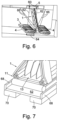
- a lowering plate 64 supports the two crafts 4, platform 3 and passage 1 when stored and when being lowered to the water. As shown most clearly in Figure 5 , the lowering plate 64 extends generally parallel to the bar 50 of the platform but spaced away therefrom towards the distal end of the leg 52 of the platform 3. After the crafts float off the lowering plate 64, the plate 64 is lowered to a safe distance below the surface of the water (as shown in FIG. 6 ) where it now acts as a stabilising plate to control the position of the platform 3 and passage 1.
- Lowering lines 62 are stored on a winch that is attached to the stowage unit 5.
- the lowering lines 62 extend from the davits 60 through the platform 3, where they are attached to the lowering plate 64, to control the descent of the evacuation system to the water.
- Stabilising bowsing control lines 66 extend between the side of the ship 2 and the passage 1 to tend to maintain the position of the passage 1 with respect to the ship 2.
- the edge of the leg 52 of the platform 3 may be arranged so that the side 1 cannot fall off due to wave (or other) movement.
- vertical walls 68 may extend above the flat upper surface of the platform 3 along all or part of the leg 52.
- longitudinal stiffening beams 70 may be provided along the underside of the leg 52.
- the walls 68 and the stiffening beams 70 are inflatable and may be formed from drop thread material of the general arrangement shown in FIG. 3 .
- Alternative inflatable structures may be used to form the side wall arrangements.
- the retaining arrangement may comprise a pair of hoops 80 (only one of which can be seen in FIG. 8 ) that are attached at or near the exit end of the passage 1 by respective passage cables 82.
- a platform rail or cable 84 (only one of which can be seen in FIG. 8 ) is attached to the interior side of each of the walls 68 and extends generally parallel to the leg 52 of the platform 3.
- the platform rails or cables 84 pass through respective ones of the hoops 80.
- the platform 3 It is desirable for the platform 3 to be held against the side of the ship 3. Without any other forces applied, the platform will rest against the side of the ship 3. However, as the ship 2 and platform 3 move on the waves, the exit end of the passage 1 will move backwards and forwards across the top surface of the platform 3.
- a platform control arrangement is provided, which is a device/arrangement or mechanism which provides a restoring force to the outboard of the platform 3 to tend to hold it against the side shell of the ship 2 (or other host vessel).
- a position restoring force is applied by the platform control arrangement that can be positioned between the end of the leg 52 of platform 3 and the exit end of the passage 1.
- the force can be generated by several methods.
- the force can be generated by fitting spring type devices 90, as shown in Figure 9 , between the exit end of the passage 1 and the distal end of the leg 52 of platform 3.
- the spring type devices may be elastically deformable objects used to store mechanical energy, such as either mechanical metal springs (e.g. coil tension springs) or elastic shock cord types.
- Multiple spring devices 90 may be used to generate the restoring force. Two are shown in Figure 9 .
- An arrangement that is not in accordance with the invention may include running a line or lines 92 over the outboard edge of the platform from the exit end of the passage 3, with a weight 94 (as shown in Figure 10 ) or sea anchor 96 (as shown in Figure 11 ) attached to the lower end of the line or lines 92.
- Guide members 98 may be provided at the distal end of the passage 3 to control the path of the line or lines 92.
- the exit end of the passage 1 is pulled inboard across the top of the platform 3, lifting the weight 94 or sea anchor 96 up, creating drag. This drag is has a similar effect to the spring force, creating the restoring force.
- the weight 94 then sinks and the sea anchor 96, which is weighted, collapses and sinks, expanding again when the passage 1 moves inboard.
- Multiple sea anchors 96 and weights 94 may be used.
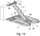
- Figures 12 to 16 show a distal end portion 100 at the exit end of the passage 1.
- the distal end portion 100 is arranged to contact the leg 52 of the platform 3, and may extend generally parallel to the upper surface of the leg 52 (in contrast to the main body of the passage 1 which is inclined with respect to the surface of the platform 3).
- the arrangement of the passage 1 and the platform 3 may be generally the same as that of Figures 1 to 11 . Similar elements are designated with the same reference signs and will be not be described again, for the sake of brevity.
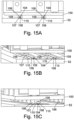
- a plurality of rails 104 extend generally parallel to one another in a longitudinal direction along the length of the leg 52 of the platform 3, as best shown in figures 14 , 15 and 16 .
- the underside of the distal end portion 100 (the side facing the upper side of the leg 52 of the platform 3) includes a plurality of corresponding generally parallel recess members 106.
- the recess members 106 are configured to receive the rails 104.
- the recess members 106 have a generally rectangular recess 107 formed therein, while the rails 104 are generally circular in cross section.
- the arrangement shown in figures 14A and 14B allows relative sliding movement in the longitudinal direction between the platform and the exit end of the slide 1 whilst restricting relative transverse movement between the exit end of the slide 1 and the platform 3.
- the rails 104 include a coupling portion 109 that is connected to the leg 52 of the platform 3 by a relatively narrow (in a transverse direction) connecter 108.
- the recess member 106 has a recess 107 that includes a chamber having a relatively narrow mouth 110 (in the transverse direction).
- the connector 108 passes through the mouth 110. Longitudinal relative sliding between the distal end portion 100 and the platform 3 is possible. However, separation of the distal end portion 100 from the platform 3 in the vertical direction is not possible because the coupling portion 109 has a greater width than the mouth 110.
- the coupling portion 109 and the chamber may have a substantially circular cross-section, although other cross-sectional shapes are possible within the scope of the invention.
- the distal end portion 100 may be configured to direct evacuees from the passage 1 in a particular direction after they exit the passage 1 so that they are in an appropriate position on the platform 3 to board the liferaft 4.
- flexible chutes or trackways 13 may be provided within the structure of the passage 1, along which evacuees slide.
- two chutes 13 are provided - 13A and 13B as best shown in the enlarged view in figure 12A .
- the distal end portion 100 includes a first guiding wall 120A associated with the first chute 13A and a second guiding wall 120B associated with the second chute 13B.
- the guiding walls 120A and 120B are curved.
- the part of the walls 120A and 120B that are connected to the common dividing wall of the chutes 13A and 13B is generally parallel to that wall.
- the opposite end of the guiding wall is almost perpendicular to the dividing wall.
- the guiding walls 120A and 120B therefore gently guide the path of an evacuee from a longitudinal direction along the chutes 13A and 13B into a transverse direction, so that the evacuees are safely guided to a particular area of the leg 52 of the platform 3 for boarding the crafts 4.
- the walls 120A and 120B may also slow the descent of the evacuees so that they arrive at the platform at a safe speed.
- the walls 120A and 120B may be supported on the distal end portion 100 by a series of supporting pillars 130.
- the distal end portion 100 may include an inclined and curved floor that bridges the difference in height between the exit of the chutes 13A and 13B and upper surface of the leg 52 of the platform 3.
- the passage 1 may have a different orientation to that shown in Figures 1 to 16 .
- the structure of the passage 1 may be generally the same as that of Figures 1 to 16 . Similar elements are designated with the same reference signs and will be not be described again, for the sake of brevity.
- the passage 1 extends in a vertical plane that is generally perpendicular to the side of the ship 2 - in the direction P shown in Figure 17 .
- the passage 1 is configured to extend aft from the evacuation point (corresponding to the position of the stowage unit 5).
- the passages 1 extend at an acute angle ⁇ to a vertical plane L extending between the bow 122 and the stern 124 of the ship 2.
- the angle ⁇ to the vertical plane L may be less than 45°.
- the passages 1 may be generally parallel to the plane L.
- a first control line 126 extends from the port side of the ship 2 and is attached to either the platform 3 or the passage 1 on the port side of the ship 2.
- a second control line 126 extends from the starboard side of the ship 2 to either the platform 3 or the passage 1 on the starboard side of the ship 2.
- the length of the control lines 126 may be adjusted by an associated control line winch 128. The shorter the control lines 126, the smaller the angle ⁇ between the passage 1 and the plane L.
Landscapes
- Engineering & Computer Science (AREA)
- Mechanical Engineering (AREA)
- Ocean & Marine Engineering (AREA)
- Health & Medical Sciences (AREA)
- General Health & Medical Sciences (AREA)
- Business, Economics & Management (AREA)
- Emergency Management (AREA)
- Chemical & Material Sciences (AREA)
- Combustion & Propulsion (AREA)
- Buildings Adapted To Withstand Abnormal External Influences (AREA)
- Emergency Lowering Means (AREA)
Claims (9)
- Rettungssystem, Folgendes umfassend:einen Durchgang (1) mit einem Eingangs- und einem Ausgangsende, undeine Plattform (3), um den Zugang zu mindestens einem Fahrzeug (4) zu ermöglichen, wobei die Plattform (3) von einer Struktur (2) zu Wasser gelassen werden kann, um die Evakuierung der Struktur (2) über den Durchgang (1) zu ermöglichen,wobei der Durchgang (1) mit Verbindungsmitteln an der Plattform (3) angebracht ist, wobei die Verbindungsmittel ein elastisch verformbares Element (90) umfassen, das als Reaktion auf eine relative Bewegung der Plattform (3) von der Struktur (2) weg elastisch verformt wird,dadurch gekennzeichnet, dass:das Eingangsende des Durchgangs (1) so ausgebildet ist, um mit einem an der Struktur (2) angebrachten Stauraum (5) verbunden zu werden;die Plattform (3) eine im Wesentlichen flache Oberseite aufweist, die konfiguriert ist, um in den Durchgang (1) einzugreifen; undder Durchgang (1) mittels Verbindungsmittel, das elastisch verformbare Glied (90) umfassend, derart an der Plattform (3) angebracht ist, dass die Plattform (3) im ausgefahrenen Zustand gegen die Struktur (2) gedrückt wird, wobei das elastisch verformbare Glied (90) zwischen dem Ausgangsende des Durchgangs (1) und einem äußeren Rand der Plattform (3) angebracht ist, und die Anordnung derart ist, dass bei einer relativen Bewegung der Plattform (3) von der Struktur (2) weg das Ausgangsende des Durchgangs (3) entlang der Oberseite der Plattform (3) nach innen bewegt wird, das elastisch verformbare Element (90) gedehnt wird und die von ihm ausgeübte Kraft zunimmt, wodurch eine Rückstellkraft ausgeübt wird, um die Plattform (3) gegen eine Seite der Struktur (2) zu ziehen.
- Rettungssystem nach Anspruch 1, wobei das elastisch verformbare Element (90) eine Zugfeder oder eine elastische Schnur umfasst.
- Rettungssystem, einen Durchgang (1) und eine Plattform (3) umfassend, um den Zugang zu mindestens einem Fahrzeug (4) zu ermöglichen, wobei die Plattform (3) von einer Struktur (2) zu Wasser gelassen werden kann, um eine Evakuierung der Struktur (2) über den Durchgang (1) zu ermöglichen, wobei der Durchgang (1) an der Plattform (3) angebracht ist, so dass die Bewegung des Durchgangs (1) relativ zur Plattform (3) in mindestens einer Richtung eingeschränkt ist, und wobei entweder die Plattform (3) oder der Durchgang (1) mindestens ein Eingriffselement aufweist, das verschiebbar in eine entsprechende Struktur des jeweils anderen Elements, also entweder der Plattform (3) oder des Durchgangs (1), eingreift, so dass die Bewegung des Durchgangs (1) relativ zur Plattform (3) in der mindestens einen Richtung eingeschränkt ist, wobei das Eingriffselement eine Schiene (104) umfasst, dadurch gekennzeichnet, dass
die entsprechende Struktur zum verschiebbaren Eingreifen der Schiene (104) ein Aussparungselement (106) umfasst, das eine Aussparung zur Aufnahme der Schiene (104) definiert, wobei die Aussparung im Querschnitt im Wesentlichen rechteckig oder halbkreisförmig ist und so konfiguriert ist, dass sie auf die Schiene (104) passt. - Rettungssystem, einen Durchgang (1) und eine Plattform (3) umfassend, um den Zugang zu mindestens einem Fahrzeug (4) zu ermöglichen, wobei die Plattform (3) von einer Struktur (2) zu Wasser gelassen werden kann, um eine Evakuierung der Struktur (2) über den Durchgang (1) zu ermöglichen, wobei der Durchgang (1) an der Plattform (3) angebracht ist, so dass die Bewegung des Durchgangs (1) relativ zur Plattform (3) in mindestens einer Richtung eingeschränkt ist, und wobei entweder die Plattform (3) oder der Durchgang (1) mindestens ein Eingriffselement aufweist, das verschiebbar in eine entsprechende Struktur des jeweils anderen Elements, also entweder der Plattform (3) oder des Durchgangs (1), eingreift, so dass die Bewegung des Durchgangs (1) relativ zur Plattform (3) in der mindestens einen Richtung eingeschränkt ist, wobei das Eingriffselement eine Schiene (104) umfasst, dadurch gekennzeichnet, dass
dass die entsprechende Struktur zum verschiebbaren Eingreifen in die Schiene (104) ein Aussparungselement (106) umfasst, das eine Aussparung zur Aufnahme der Schiene (104) definiert, wobei die Schiene (104) einen Kupplungsabschnitt (109) enthält, der über ein relativ schmales Verbindungselement (108) mit der Plattform (3) bzw. dem Durchgang (1) verbunden ist, und wobei die Aussparung eine Kammer mit einer relativ schmalen Öffnung (110) umfasst, wobei die Kammer so konfiguriert ist, dass sie den Abschnitt des Kupplungsstücks (109) der Schiene (104) aufnimmt, wobei sich das Verbindungsstück (108) durch die Öffnung (110) erstreckt. - Rettungssystem nach Anspruch 4, wobei das Kupplungsstück (109) und/oder die Kammer im Wesentlichen einen kreisförmigen Querschnitt haben.
- Rettungssystem nach einem der Ansprüche 3 bis 5, wobei die Plattform (3) mit dem Durchgang (1) gekoppelt ist, um ein Anheben des Durchgangs (1) von einer Oberseite der Plattform (3) zu begrenzen.
- Rettungssystem nach einem der Ansprüche 1 bis 6, wobei der Durchgang (1) und/oder die Plattform (3) aufblasbar sind.
- Rettungssystem nach einem der Ansprüche 1 bis 7, wobei der Durchgang (1) zur Plattform (3) und/oder zur Struktur (2) bei Verwendung geneigt ist.
- Rettungssystem nach einem der Ansprüche 1 bis 8, ferner umfassend das mindestens eine Fahrzeug (4), wie beispielsweise ein Rettungsfloß, und welches vorzugsweise aufblasbar ist.
Applications Claiming Priority (3)
| Application Number | Priority Date | Filing Date | Title |
|---|---|---|---|
| GBGB1707684.5A GB201707684D0 (en) | 2017-05-12 | 2017-05-12 | Escape system |
| GB1804260.6A GB2563711B (en) | 2017-05-12 | 2018-03-16 | Escape system |
| PCT/EP2018/062245 WO2018206785A1 (en) | 2017-05-12 | 2018-05-11 | Escape system |
Publications (2)
| Publication Number | Publication Date |
|---|---|
| EP3621871A1 EP3621871A1 (de) | 2020-03-18 |
| EP3621871B1 true EP3621871B1 (de) | 2024-12-11 |
Family
ID=59201696
Family Applications (1)
| Application Number | Title | Priority Date | Filing Date |
|---|---|---|---|
| EP18724842.2A Active EP3621871B1 (de) | 2017-05-12 | 2018-05-11 | Fluchtsystem |
Country Status (7)
| Country | Link |
|---|---|
| US (1) | US11649023B2 (de) |
| EP (1) | EP3621871B1 (de) |
| AU (1) | AU2018265236B2 (de) |
| DK (1) | DK3621871T3 (de) |
| FI (1) | FI3621871T3 (de) |
| GB (2) | GB201707684D0 (de) |
| WO (1) | WO2018206785A1 (de) |
Families Citing this family (4)
| Publication number | Priority date | Publication date | Assignee | Title |
|---|---|---|---|---|
| EP3971089A1 (de) * | 2020-09-18 | 2022-03-23 | Goodrich Corporation | Evakuierungsrutsche mit aufblasbarer fallmaschenstruktur |
| US11673674B2 (en) | 2020-09-18 | 2023-06-13 | Goodrich Corporation | Evacuation slide having drop stitch inflatable structure |
| CN114537595B (zh) * | 2022-01-27 | 2023-12-01 | 大连海事大学 | 一种充气滑梯式海上撤离系统 |
| CN119434164B (zh) * | 2025-01-09 | 2025-03-11 | 中交第四航务工程局有限公司 | 靠船构件吊模安装装置 |
Family Cites Families (13)
| Publication number | Priority date | Publication date | Assignee | Title |
|---|---|---|---|---|
| GB2040844B (en) * | 1979-01-11 | 1983-02-09 | Rfd Inflatables Ltd | Marine escape slide system |
| GB2131369B (en) * | 1982-12-06 | 1986-02-12 | Rfd Ltd | Marine escape system |
| NO180265C (no) * | 1992-07-10 | 1997-03-19 | Selantic Ind As | Anordning ved redningsflåter på skip |
| WO1995014605A1 (en) * | 1993-11-22 | 1995-06-01 | Liferaft Systems Australia Pty. Limited | Marine evacuation system |
| GB9405117D0 (en) * | 1994-03-16 | 1994-04-27 | Telescape Uk Ltd | Improved escape chute |
| NO306770B1 (no) * | 1996-02-13 | 1999-12-20 | Koppernaes As | Anordning for evakuering av personer fra skip |
| NO321073B1 (no) * | 2003-08-29 | 2006-03-13 | Viking Life Saving Equipment N | Anordning ved evakueringssystem |
| WO2008040359A1 (en) * | 2006-10-06 | 2008-04-10 | Viking Life-Saving Equipment A/S | Escape system with self-adjusting length |
| EP2720939B2 (de) * | 2011-06-17 | 2023-02-08 | Viking Life-Saving Equipment A/S | Evakuierungssystem |
| US20140165899A1 (en) * | 2012-12-17 | 2014-06-19 | Paul Ceeney | Escape vessel with detachable landing |
| GB2547641B (en) | 2016-02-18 | 2021-06-30 | Survitec Group Ltd | Survival craft |
| SG11201811822WA (en) | 2016-07-05 | 2019-01-30 | Salunda Ltd | Sensor for a fingerboard latch assembly |
| GB2555576B (en) | 2016-10-26 | 2021-09-15 | Survitec Group Ltd | Evacuation system |
-
2017
- 2017-05-12 GB GBGB1707684.5A patent/GB201707684D0/en not_active Ceased
-
2018
- 2018-03-16 GB GB1804260.6A patent/GB2563711B/en active Active
- 2018-05-11 AU AU2018265236A patent/AU2018265236B2/en active Active
- 2018-05-11 US US16/612,696 patent/US11649023B2/en active Active
- 2018-05-11 FI FIEP18724842.2T patent/FI3621871T3/fi active
- 2018-05-11 EP EP18724842.2A patent/EP3621871B1/de active Active
- 2018-05-11 DK DK18724842.2T patent/DK3621871T3/da active
- 2018-05-11 WO PCT/EP2018/062245 patent/WO2018206785A1/en not_active Ceased
Also Published As
| Publication number | Publication date |
|---|---|
| GB201707684D0 (en) | 2017-06-28 |
| FI3621871T3 (fi) | 2025-03-20 |
| GB2563711A (en) | 2018-12-26 |
| AU2018265236B2 (en) | 2023-11-23 |
| GB201804260D0 (en) | 2018-05-02 |
| DK3621871T3 (da) | 2025-03-17 |
| GB2563711B (en) | 2021-11-17 |
| AU2018265236A1 (en) | 2019-11-28 |
| EP3621871A1 (de) | 2020-03-18 |
| US11649023B2 (en) | 2023-05-16 |
| US20200062358A1 (en) | 2020-02-27 |
| WO2018206785A1 (en) | 2018-11-15 |
Similar Documents
| Publication | Publication Date | Title |
|---|---|---|
| EP3621871B1 (de) | Fluchtsystem | |
| KR20000010566A (ko) | 보트의 진수 및 양육 장치 | |
| EP3003846B1 (de) | Gestellanordnung für booten | |
| EP3649043B1 (de) | Fluchtsystem | |
| US9643691B2 (en) | Launch and recovery device | |
| GB2061833A (en) | Marine service vessels with an auxiliary boom for emergency evacuation of offshore platforms | |
| US4203504A (en) | Method and system for escaping from an offshore drilling platform | |
| KR20160030738A (ko) | 구명보트용 진수 장치 | |
| US12473052B2 (en) | System for handling marine or underwater drones by floating pontoon with removable drone interface module, adapted ship | |
| GB2225753A (en) | Abandonment systems for structures surrounded by water | |
| KR101167933B1 (ko) | 선박용 구명보트의 추진형 입수 가이드 장치 | |
| KR20180002424U (ko) | 선박용 승하선 장치 | |
| WO2012032023A1 (en) | Evacuation system with a positioning system for positioning a floatable unit | |
| WO2014131820A1 (en) | A marine evacuation system | |
| EP1829781B1 (de) | Vertäuungsvorrichtung für eine schwimmfähige Einheit | |
| RU2483331C1 (ru) | Комплекс для буксировки забортного сейсмооборудования | |
| EP4484268A1 (de) | Seeevakuierungssystem | |
| RU2323121C1 (ru) | Плавучий причал | |
| WO2024180173A1 (en) | A maritime evacuation system | |
| KR20150000224U (ko) | 잠수함의 접이식 현문 | |
| KR101549233B1 (ko) | 헬리데크를 이용한 비상탈출장치 | |
| CN120331111A (zh) | 一种刚柔组合浮桥系统及浮桥系统的搭设方法 | |
| KR20100076103A (ko) | 대형 위그선의 정박용 장치 및 방법 | |
| WO2015148452A1 (en) | Launch and recovery device |
Legal Events
| Date | Code | Title | Description |
|---|---|---|---|
| STAA | Information on the status of an ep patent application or granted ep patent |
Free format text: STATUS: UNKNOWN |
|
| STAA | Information on the status of an ep patent application or granted ep patent |
Free format text: STATUS: THE INTERNATIONAL PUBLICATION HAS BEEN MADE |
|
| PUAI | Public reference made under article 153(3) epc to a published international application that has entered the european phase |
Free format text: ORIGINAL CODE: 0009012 |
|
| STAA | Information on the status of an ep patent application or granted ep patent |
Free format text: STATUS: REQUEST FOR EXAMINATION WAS MADE |
|
| 17P | Request for examination filed |
Effective date: 20191105 |
|
| AK | Designated contracting states |
Kind code of ref document: A1 Designated state(s): AL AT BE BG CH CY CZ DE DK EE ES FI FR GB GR HR HU IE IS IT LI LT LU LV MC MK MT NL NO PL PT RO RS SE SI SK SM TR |
|
| AX | Request for extension of the european patent |
Extension state: BA ME |
|
| DAV | Request for validation of the european patent (deleted) | ||
| DAX | Request for extension of the european patent (deleted) | ||
| STAA | Information on the status of an ep patent application or granted ep patent |
Free format text: STATUS: EXAMINATION IS IN PROGRESS |
|
| 17Q | First examination report despatched |
Effective date: 20230609 |
|
| REG | Reference to a national code |
Ref country code: DE Ref legal event code: R079 Free format text: PREVIOUS MAIN CLASS: B63C0009220000 Ipc: B63B0027140000 Ref country code: DE Ref legal event code: R079 Ref document number: 602018077482 Country of ref document: DE Free format text: PREVIOUS MAIN CLASS: B63C0009220000 Ipc: B63B0027140000 |
|
| GRAP | Despatch of communication of intention to grant a patent |
Free format text: ORIGINAL CODE: EPIDOSNIGR1 |
|
| STAA | Information on the status of an ep patent application or granted ep patent |
Free format text: STATUS: GRANT OF PATENT IS INTENDED |
|
| RIC1 | Information provided on ipc code assigned before grant |
Ipc: B64D 25/14 20060101ALI20240620BHEP Ipc: B63B 27/14 20060101AFI20240620BHEP |
|
| INTG | Intention to grant announced |
Effective date: 20240704 |
|
| GRAS | Grant fee paid |
Free format text: ORIGINAL CODE: EPIDOSNIGR3 |
|
| GRAA | (expected) grant |
Free format text: ORIGINAL CODE: 0009210 |
|
| STAA | Information on the status of an ep patent application or granted ep patent |
Free format text: STATUS: THE PATENT HAS BEEN GRANTED |
|
| AK | Designated contracting states |
Kind code of ref document: B1 Designated state(s): AL AT BE BG CH CY CZ DE DK EE ES FI FR GB GR HR HU IE IS IT LI LT LU LV MC MK MT NL NO PL PT RO RS SE SI SK SM TR |
|
| REG | Reference to a national code |
Ref country code: GB Ref legal event code: FG4D |
|
| REG | Reference to a national code |
Ref country code: CH Ref legal event code: EP |
|
| REG | Reference to a national code |
Ref country code: IE Ref legal event code: FG4D |
|
| REG | Reference to a national code |
Ref country code: DE Ref legal event code: R096 Ref document number: 602018077482 Country of ref document: DE |
|
| REG | Reference to a national code |
Ref country code: DK Ref legal event code: T3 Effective date: 20250310 |
|
| REG | Reference to a national code |
Ref country code: FI Ref legal event code: FGE |
|
| REG | Reference to a national code |
Ref country code: LT Ref legal event code: MG9D |
|
| PG25 | Lapsed in a contracting state [announced via postgrant information from national office to epo] |
Ref country code: HR Free format text: LAPSE BECAUSE OF FAILURE TO SUBMIT A TRANSLATION OF THE DESCRIPTION OR TO PAY THE FEE WITHIN THE PRESCRIBED TIME-LIMIT Effective date: 20241211 |
|
| PG25 | Lapsed in a contracting state [announced via postgrant information from national office to epo] |
Ref country code: BG Free format text: LAPSE BECAUSE OF FAILURE TO SUBMIT A TRANSLATION OF THE DESCRIPTION OR TO PAY THE FEE WITHIN THE PRESCRIBED TIME-LIMIT Effective date: 20241211 |
|
| REG | Reference to a national code |
Ref country code: NL Ref legal event code: MP Effective date: 20241211 |
|
| PG25 | Lapsed in a contracting state [announced via postgrant information from national office to epo] |
Ref country code: ES Free format text: LAPSE BECAUSE OF FAILURE TO SUBMIT A TRANSLATION OF THE DESCRIPTION OR TO PAY THE FEE WITHIN THE PRESCRIBED TIME-LIMIT Effective date: 20241211 |
|
| PG25 | Lapsed in a contracting state [announced via postgrant information from national office to epo] |
Ref country code: NO Free format text: LAPSE BECAUSE OF FAILURE TO SUBMIT A TRANSLATION OF THE DESCRIPTION OR TO PAY THE FEE WITHIN THE PRESCRIBED TIME-LIMIT Effective date: 20250311 |
|
| PG25 | Lapsed in a contracting state [announced via postgrant information from national office to epo] |
Ref country code: LV Free format text: LAPSE BECAUSE OF FAILURE TO SUBMIT A TRANSLATION OF THE DESCRIPTION OR TO PAY THE FEE WITHIN THE PRESCRIBED TIME-LIMIT Effective date: 20241211 Ref country code: GR Free format text: LAPSE BECAUSE OF FAILURE TO SUBMIT A TRANSLATION OF THE DESCRIPTION OR TO PAY THE FEE WITHIN THE PRESCRIBED TIME-LIMIT Effective date: 20250312 |
|
| PG25 | Lapsed in a contracting state [announced via postgrant information from national office to epo] |
Ref country code: RS Free format text: LAPSE BECAUSE OF FAILURE TO SUBMIT A TRANSLATION OF THE DESCRIPTION OR TO PAY THE FEE WITHIN THE PRESCRIBED TIME-LIMIT Effective date: 20250311 |
|
| PG25 | Lapsed in a contracting state [announced via postgrant information from national office to epo] |
Ref country code: NL Free format text: LAPSE BECAUSE OF FAILURE TO SUBMIT A TRANSLATION OF THE DESCRIPTION OR TO PAY THE FEE WITHIN THE PRESCRIBED TIME-LIMIT Effective date: 20241211 |
|
| REG | Reference to a national code |
Ref country code: AT Ref legal event code: MK05 Ref document number: 1750211 Country of ref document: AT Kind code of ref document: T Effective date: 20241211 |
|
| PG25 | Lapsed in a contracting state [announced via postgrant information from national office to epo] |
Ref country code: SM Free format text: LAPSE BECAUSE OF FAILURE TO SUBMIT A TRANSLATION OF THE DESCRIPTION OR TO PAY THE FEE WITHIN THE PRESCRIBED TIME-LIMIT Effective date: 20241211 |
|
| PGFP | Annual fee paid to national office [announced via postgrant information from national office to epo] |
Ref country code: FI Payment date: 20250526 Year of fee payment: 8 |
|
| PG25 | Lapsed in a contracting state [announced via postgrant information from national office to epo] |
Ref country code: PL Free format text: LAPSE BECAUSE OF FAILURE TO SUBMIT A TRANSLATION OF THE DESCRIPTION OR TO PAY THE FEE WITHIN THE PRESCRIBED TIME-LIMIT Effective date: 20241211 |
|
| PGFP | Annual fee paid to national office [announced via postgrant information from national office to epo] |
Ref country code: DE Payment date: 20250529 Year of fee payment: 8 |
|
| PGFP | Annual fee paid to national office [announced via postgrant information from national office to epo] |
Ref country code: DK Payment date: 20250526 Year of fee payment: 8 |
|
| PG25 | Lapsed in a contracting state [announced via postgrant information from national office to epo] |
Ref country code: IS Free format text: LAPSE BECAUSE OF FAILURE TO SUBMIT A TRANSLATION OF THE DESCRIPTION OR TO PAY THE FEE WITHIN THE PRESCRIBED TIME-LIMIT Effective date: 20250411 |
|
| PGFP | Annual fee paid to national office [announced via postgrant information from national office to epo] |
Ref country code: IT Payment date: 20250521 Year of fee payment: 8 |
|
| PG25 | Lapsed in a contracting state [announced via postgrant information from national office to epo] |
Ref country code: PT Free format text: LAPSE BECAUSE OF FAILURE TO SUBMIT A TRANSLATION OF THE DESCRIPTION OR TO PAY THE FEE WITHIN THE PRESCRIBED TIME-LIMIT Effective date: 20250411 |
|
| PG25 | Lapsed in a contracting state [announced via postgrant information from national office to epo] |
Ref country code: EE Free format text: LAPSE BECAUSE OF FAILURE TO SUBMIT A TRANSLATION OF THE DESCRIPTION OR TO PAY THE FEE WITHIN THE PRESCRIBED TIME-LIMIT Effective date: 20241211 |
|
| PGFP | Annual fee paid to national office [announced via postgrant information from national office to epo] |
Ref country code: FR Payment date: 20250526 Year of fee payment: 8 |
|
| PG25 | Lapsed in a contracting state [announced via postgrant information from national office to epo] |
Ref country code: AT Free format text: LAPSE BECAUSE OF FAILURE TO SUBMIT A TRANSLATION OF THE DESCRIPTION OR TO PAY THE FEE WITHIN THE PRESCRIBED TIME-LIMIT Effective date: 20241211 Ref country code: RO Free format text: LAPSE BECAUSE OF FAILURE TO SUBMIT A TRANSLATION OF THE DESCRIPTION OR TO PAY THE FEE WITHIN THE PRESCRIBED TIME-LIMIT Effective date: 20241211 |
|
| PG25 | Lapsed in a contracting state [announced via postgrant information from national office to epo] |
Ref country code: SK Free format text: LAPSE BECAUSE OF FAILURE TO SUBMIT A TRANSLATION OF THE DESCRIPTION OR TO PAY THE FEE WITHIN THE PRESCRIBED TIME-LIMIT Effective date: 20241211 |
|
| PG25 | Lapsed in a contracting state [announced via postgrant information from national office to epo] |
Ref country code: CZ Free format text: LAPSE BECAUSE OF FAILURE TO SUBMIT A TRANSLATION OF THE DESCRIPTION OR TO PAY THE FEE WITHIN THE PRESCRIBED TIME-LIMIT Effective date: 20241211 |
|
| PG25 | Lapsed in a contracting state [announced via postgrant information from national office to epo] |
Ref country code: SE Free format text: LAPSE BECAUSE OF FAILURE TO SUBMIT A TRANSLATION OF THE DESCRIPTION OR TO PAY THE FEE WITHIN THE PRESCRIBED TIME-LIMIT Effective date: 20241211 |
|
| REG | Reference to a national code |
Ref country code: DE Ref legal event code: R097 Ref document number: 602018077482 Country of ref document: DE |
|
| PLBE | No opposition filed within time limit |
Free format text: ORIGINAL CODE: 0009261 |
|
| STAA | Information on the status of an ep patent application or granted ep patent |
Free format text: STATUS: NO OPPOSITION FILED WITHIN TIME LIMIT |
|
| REG | Reference to a national code |
Ref country code: CH Ref legal event code: L10 Free format text: ST27 STATUS EVENT CODE: U-0-0-L10-L00 (AS PROVIDED BY THE NATIONAL OFFICE) Effective date: 20251022 |
|
| 26N | No opposition filed |
Effective date: 20250912 |
|
| REG | Reference to a national code |
Ref country code: CH Ref legal event code: H13 Free format text: ST27 STATUS EVENT CODE: U-0-0-H10-H13 (AS PROVIDED BY THE NATIONAL OFFICE) Effective date: 20251223 |
|
| PG25 | Lapsed in a contracting state [announced via postgrant information from national office to epo] |
Ref country code: LU Free format text: LAPSE BECAUSE OF NON-PAYMENT OF DUE FEES Effective date: 20250511 |
|
| PG25 | Lapsed in a contracting state [announced via postgrant information from national office to epo] |
Ref country code: CH Free format text: LAPSE BECAUSE OF NON-PAYMENT OF DUE FEES Effective date: 20250531 |
|
| GBPC | Gb: european patent ceased through non-payment of renewal fee |
Effective date: 20250511 |
|
| REG | Reference to a national code |
Ref country code: BE Ref legal event code: MM Effective date: 20250531 |
|
| PG25 | Lapsed in a contracting state [announced via postgrant information from national office to epo] |
Ref country code: MC Free format text: LAPSE BECAUSE OF FAILURE TO SUBMIT A TRANSLATION OF THE DESCRIPTION OR TO PAY THE FEE WITHIN THE PRESCRIBED TIME-LIMIT Effective date: 20241211 |
|
| PG25 | Lapsed in a contracting state [announced via postgrant information from national office to epo] |
Ref country code: GB Free format text: LAPSE BECAUSE OF NON-PAYMENT OF DUE FEES Effective date: 20250511 |
|
| PG25 | Lapsed in a contracting state [announced via postgrant information from national office to epo] |
Ref country code: IE Free format text: LAPSE BECAUSE OF NON-PAYMENT OF DUE FEES Effective date: 20250511 |
|
| PG25 | Lapsed in a contracting state [announced via postgrant information from national office to epo] |
Ref country code: BE Free format text: LAPSE BECAUSE OF NON-PAYMENT OF DUE FEES Effective date: 20250531 |