EP3620754B1 - Magnethalter und hubsensor mit dem magnethalter - Google Patents
Magnethalter und hubsensor mit dem magnethalter Download PDFInfo
- Publication number
- EP3620754B1 EP3620754B1 EP18193005.8A EP18193005A EP3620754B1 EP 3620754 B1 EP3620754 B1 EP 3620754B1 EP 18193005 A EP18193005 A EP 18193005A EP 3620754 B1 EP3620754 B1 EP 3620754B1
- Authority
- EP
- European Patent Office
- Prior art keywords
- plunger
- cylindrical body
- sleeve
- sensor
- magnet
- Prior art date
- Legal status (The legal status is an assumption and is not a legal conclusion. Google has not performed a legal analysis and makes no representation as to the accuracy of the status listed.)
- Active
Links
Images

Classifications
-
- G—PHYSICS
- G01—MEASURING; TESTING
- G01D—MEASURING NOT SPECIALLY ADAPTED FOR A SPECIFIC VARIABLE; ARRANGEMENTS FOR MEASURING TWO OR MORE VARIABLES NOT COVERED IN A SINGLE OTHER SUBCLASS; TARIFF METERING APPARATUS; MEASURING OR TESTING NOT OTHERWISE PROVIDED FOR
- G01D5/00—Mechanical means for transferring the output of a sensing member; Means for converting the output of a sensing member to another variable where the form or nature of the sensing member does not constrain the means for converting; Transducers not specially adapted for a specific variable
- G01D5/12—Mechanical means for transferring the output of a sensing member; Means for converting the output of a sensing member to another variable where the form or nature of the sensing member does not constrain the means for converting; Transducers not specially adapted for a specific variable using electric or magnetic means
- G01D5/14—Mechanical means for transferring the output of a sensing member; Means for converting the output of a sensing member to another variable where the form or nature of the sensing member does not constrain the means for converting; Transducers not specially adapted for a specific variable using electric or magnetic means influencing the magnitude of a current or voltage
- G01D5/16—Mechanical means for transferring the output of a sensing member; Means for converting the output of a sensing member to another variable where the form or nature of the sensing member does not constrain the means for converting; Transducers not specially adapted for a specific variable using electric or magnetic means influencing the magnitude of a current or voltage by varying resistance
-
- G—PHYSICS
- G01—MEASURING; TESTING
- G01D—MEASURING NOT SPECIALLY ADAPTED FOR A SPECIFIC VARIABLE; ARRANGEMENTS FOR MEASURING TWO OR MORE VARIABLES NOT COVERED IN A SINGLE OTHER SUBCLASS; TARIFF METERING APPARATUS; MEASURING OR TESTING NOT OTHERWISE PROVIDED FOR
- G01D11/00—Component parts of measuring arrangements not specially adapted for a specific variable
- G01D11/24—Housings ; Casings for instruments
- G01D11/245—Housings for sensors
-
- B—PERFORMING OPERATIONS; TRANSPORTING
- B60—VEHICLES IN GENERAL
- B60T—VEHICLE BRAKE CONTROL SYSTEMS OR PARTS THEREOF; BRAKE CONTROL SYSTEMS OR PARTS THEREOF, IN GENERAL; ARRANGEMENT OF BRAKING ELEMENTS ON VEHICLES IN GENERAL; PORTABLE DEVICES FOR PREVENTING UNWANTED MOVEMENT OF VEHICLES; VEHICLE MODIFICATIONS TO FACILITATE COOLING OF BRAKES
- B60T7/00—Brake-action initiating means
- B60T7/02—Brake-action initiating means for personal initiation
- B60T7/04—Brake-action initiating means for personal initiation foot actuated
- B60T7/042—Brake-action initiating means for personal initiation foot actuated by electrical means, e.g. using travel or force sensors
-
- F—MECHANICAL ENGINEERING; LIGHTING; HEATING; WEAPONS; BLASTING
- F16—ENGINEERING ELEMENTS AND UNITS; GENERAL MEASURES FOR PRODUCING AND MAINTAINING EFFECTIVE FUNCTIONING OF MACHINES OR INSTALLATIONS; THERMAL INSULATION IN GENERAL
- F16D—COUPLINGS FOR TRANSMITTING ROTATION; CLUTCHES; BRAKES
- F16D66/00—Arrangements for monitoring working conditions, e.g. wear, temperature
-
- G—PHYSICS
- G01—MEASURING; TESTING
- G01D—MEASURING NOT SPECIALLY ADAPTED FOR A SPECIFIC VARIABLE; ARRANGEMENTS FOR MEASURING TWO OR MORE VARIABLES NOT COVERED IN A SINGLE OTHER SUBCLASS; TARIFF METERING APPARATUS; MEASURING OR TESTING NOT OTHERWISE PROVIDED FOR
- G01D5/00—Mechanical means for transferring the output of a sensing member; Means for converting the output of a sensing member to another variable where the form or nature of the sensing member does not constrain the means for converting; Transducers not specially adapted for a specific variable
- G01D5/12—Mechanical means for transferring the output of a sensing member; Means for converting the output of a sensing member to another variable where the form or nature of the sensing member does not constrain the means for converting; Transducers not specially adapted for a specific variable using electric or magnetic means
- G01D5/14—Mechanical means for transferring the output of a sensing member; Means for converting the output of a sensing member to another variable where the form or nature of the sensing member does not constrain the means for converting; Transducers not specially adapted for a specific variable using electric or magnetic means influencing the magnitude of a current or voltage
- G01D5/142—Mechanical means for transferring the output of a sensing member; Means for converting the output of a sensing member to another variable where the form or nature of the sensing member does not constrain the means for converting; Transducers not specially adapted for a specific variable using electric or magnetic means influencing the magnitude of a current or voltage using Hall-effect devices
- G01D5/145—Mechanical means for transferring the output of a sensing member; Means for converting the output of a sensing member to another variable where the form or nature of the sensing member does not constrain the means for converting; Transducers not specially adapted for a specific variable using electric or magnetic means influencing the magnitude of a current or voltage using Hall-effect devices influenced by the relative movement between the Hall device and magnetic fields
-
- F—MECHANICAL ENGINEERING; LIGHTING; HEATING; WEAPONS; BLASTING
- F16—ENGINEERING ELEMENTS AND UNITS; GENERAL MEASURES FOR PRODUCING AND MAINTAINING EFFECTIVE FUNCTIONING OF MACHINES OR INSTALLATIONS; THERMAL INSULATION IN GENERAL
- F16D—COUPLINGS FOR TRANSMITTING ROTATION; CLUTCHES; BRAKES
- F16D66/00—Arrangements for monitoring working conditions, e.g. wear, temperature
- F16D2066/003—Position, angle or speed
-
- F—MECHANICAL ENGINEERING; LIGHTING; HEATING; WEAPONS; BLASTING
- F16—ENGINEERING ELEMENTS AND UNITS; GENERAL MEASURES FOR PRODUCING AND MAINTAINING EFFECTIVE FUNCTIONING OF MACHINES OR INSTALLATIONS; THERMAL INSULATION IN GENERAL
- F16D—COUPLINGS FOR TRANSMITTING ROTATION; CLUTCHES; BRAKES
- F16D2121/00—Type of actuator operation force
- F16D2121/02—Fluid pressure
- F16D2121/04—Fluid pressure acting on a piston-type actuator, e.g. for liquid pressure
Definitions
- the present invention relates to a magnet holder and a stroke sensor with the magnet holder to determine an axial displacement in a plunger/cylinder arrangement.
- KR 2017 009 62 48 discloses another linear actuator with a magneto-based shift sensor magnetic and DE 10 2008 052 416 a known actuating element for a gear change transmission, wherein a magnetic sensor unit detects the relative position between the actuator and a stationary part.
- DE 196 37 296 A1 discloses a conventional stroke sensor for a piston with a magneto-resistive element arranged in a cylindrical body, wherein the associated magnet is mounted on the piston. Upon an axial displacement of the piston an electric signal is generated in the magneto-resistive element dependent on the axial position of the piston. This sensor is, however, arranged within the cylinder and as such it is exposed to moisture or dirt inside the cylinder.
- US 9,266,517 B2 Another conventional sensor module for a master cylinder is disclosed in US 9,266,517 B2 , which also relies on a magneto-resistive element and includes a corresponding magnet.
- This sensor module uses a separate sensor chamber in which the magnet is mounted on an end portion of an additional plunger that moves back and forth unisonous with a plunger of the master cylinder whose position shall be sensed.
- this sensor module provides a separate chamber for the magneto-resistive element and is thus less prone to moisture and dirt, the additional plunger as magnet holder with its guiding makes the sensor arrangement more complicated.
- the present invention relates to a stroke sensor according to claim 1 with a magnet holder.
- the stroke sensor comprises a magneto-resistive sensor with a magnet and is configured to sense a linear displacement of a plunger in a cylindrical body of a plunger/cylinder arrangement.
- the magnet holder comprises a sleeve enveloping the plunger, a mounting for the magnet radially protruding from the sleeve, and a cover for closing the sleeve on one side.
- the cover comprises an opening for allowing the linear displacement of the plunger (e.g. by guiding the plunger rod). The sleeve and the cover move relative to each other, when the plunger performs the linear displacement in the cylindrical body.
- envelopeing shall indicate, that the sleeve may encircle the plunger completely around the plunger in a cross-section perpendicular to the axial displacement direction. However, enveloping does not imply that plunger is encircled in the axial direction. Instead, with respect to the axial direction at least part of the plunger (e.g. a plunger rod) may protrude out of the sleeve.
- the magneto-resistive sensors can be any sensor that generates a sensor signal dependent on a change of a magnet field resulting in a change of a resistance in a sensor element.
- the change in the magnetic field is caused by the axial displacement of the magnet relative to the magneto-resistive sensor.
- Examples for such magneto-resistive sensors uses the Hall-effect, GMR- (giant magneto-resistance), AMR- (anisotropic magneto-resistance), TMR- (tunnel magneto-resistance) effect to generate respective sensor signals.
- the corresponding Hall-sensor does not need magnet material, whereas the corresponding GMR-, TMR-, AMR-sensor rely at least in part on magnetic materials.
- the present invention shall not be limited on a particular example for the magneto-resistive sensor.
- the plunger/cylinder arrangement comprises a piston configured to move together with the plunger inside the cylindrical body.
- the sleeve may be formed to envelope at least an upper portion of the piston.
- the piston and the plunger are, however, separate elements which are detachable from one another.
- the plunger may perform a rotation and the linear displacement relative to the cylindrical body.
- the mounting may form together with the sleeve an integral part and may be configured to provide a rotational interlock between the sleeve and the cylindrical body, while allowing the linear displacement (linear movement) within the cylindrical body.
- the rotational interlock may be proved by an axial slot (elongated/linear opening) within the cylindrical body and the sleeve may comprise a pin that engages to the axial slot and prevents the relative rotation.
- the mounting of the magnet holder may act as such a pin. As a result of this interlocking engagement the magnet will move linearly relative to the magneto-resistive sensor and thus provides a well-defined sensor signal.
- the sleeve is adapted to perform the linear displacement together with the plunger and/or the piston.
- This may likewise be implemented by a pin/groove engagement between the sleeve and the plunger.
- a pin/groove engagement may likewise be formed between the sleeve the piston.
- the present invention relates also to a stroke sensor comprising a magneto-resistive sensor with a magnet, which may be a Hall sensor and is configured to sense a linear displacement of a plunger in a cylindrical body.
- the stroke sensor includes a magnet holder as described before.
- the stroke sensor includes a chamber arranged at a side portion of the cylindrical body and sealed from an interior space of the cylindrical body.
- the stroke sensor may include a removable side cover that provides a closure for the chamber.
- the magneto-resistive sensor may be arranged together with its magnet inside the chamber.
- the cover may be adapted to close the cylindrical body and the chamber.
- a printed circuit board is attached to the removable side cover, wherein the printed circuit boards holds the magneto-resistive sensor in the chamber.
- the present invention relates also to a plunger/cylinder arrangement for a brake system of a vehicle, in particular a commercial vehicle.
- the plunger/cylinder arrangement includes a cylindrical body, a plunger, and a stroke sensor as described before.
- the plunger is able to perform a linear displacement in the cylindrical body, which may correspond to a brake demand.
- the stroke sensor may sense this brake demand for the vehicle.
- the cylindrical body comprises an axial slot (split-like opening) for receiving part of the mounting to provide an axial guidance for the sleeve while preventing relative rotations between the sleeve and the cylindrical body.
- the plunger/cylinder arrangement includes a piston configured to move in at least one direction together with the plunger inside the cylindrical body, wherein the sleeve is adapted to slide inside the cylindrical body and to encircle at least an upper portion of the piston.
- a sealing between a lower portion of the piston and the cylindrical body may be provided to seal the chamber from an interior space of the cylindrical body.
- Embodiments of the present invention relates also to a vehicle with the plunger/cylinder arrangement as described before.
- the vehicle may be a commercial vehicle and the plunger/cylinder arrangement may be part of a braking system of the vehicle.
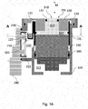
- Fig. 1A and Fig. 1B depict a magnet holder with a stroke sensor for a plunger/cylinder arrangement.
- the stroke sensor comprises a magneto-resistive sensor 210 with a magnet 220 and the plunger/cylinder arrangement comprises a plunger 310 and a cylindrical body 320 that can move relative to each other along the axial direction M (linear displacement).
- the magnet holder comprises a sleeve 110 encircling the plunger 310, a mounting 120 for the magnet 220 protruding radially outward from the sleeve 110, and a cover 130 for closing the sleeve 110 on one side.
- the cover 130 has an opening 135 for allowing the linear displacement of the plunger 310 therethrough.
- the plunger 310 may comprise a plunger rod 312 extending through the opening 135 and a piston part 314 (broadened portion) arranged in an interior space 322 of the cylindrical body 320.
- the sleeve 110 and the cover 130 move relative to each other, when the plunger 310 performs the linear displacement M through the interior space 322 of the cylindrical body 320.
- the plunger 310 abuts to a piston 330 to push the piston 330 upon the linear displacement M.
- the plunger/cylinder arrangement may further include at least one spring (not shown in Fig. 1A ) to provide a bias force pressing the piston 330 to the plunger 310 (in Fig. 1A upward).
- the piston 330 couples to the plunger 310 via other coupling elements (e.g. a snap or click connection).
- the plunger 310 couples likewise to the sleeve 110 preventing a relative displacement of the sleeve 110 and the plunger 310 in the axial direction M.
- the sleeve 110 may be coupled to the piston 330 rather than to the plunger 310.
- the plunger 310 and the sleeve 110 may rotate relative to each other about the axial direction M.
- This coupling may be implemented by groove/pin coupling 115 involving e.g. protrusions or a protruding ring extending radially inwards from the sleeve 110 and corresponding recesses or grooves formed at an outer circumference of the plunger 310 or of the piston 330 (or its broadened portion). It may also be implemented the other way around, i.e. the groove/recess is formed in the sleeve 110 and the protrusion(s) on the plunger 310.
- the embodiment depicted in Fig. 1B differs from the embodiment in Fig. 1A only in that the groove/pin coupling 115 involves now the sleeve 110 and the piston 330 (not the plunger). All other components may be arranged in the same way.
- the mounting 120 for the magnet 220 extends radially outwards from the sleeve 110 such that the magnet 220 is held within a chamber 230 separate from the interior space 322 of the cylindrical body 320.
- the chamber 230 is formed at a side portion of the cylindrical body 320 and is covered by a removable side cover 240.
- the magneto-resistive sensor 210 is arranged together with the magnet 220 inside the chamber 230, which is sealed from the interior space 322 of the cylindrical body 320 by sealing means 340 (e.g. a sealing ring).
- the magneto-resistive sensor 210 may be arranged on a printed circuit board 250 that in turn may be attached to the removable side cover 240 of the chamber 230.
- the cover 130 is adapted to provide a closure for the cylindrical body 320 and the sleeve 110 and/or the chamber 230.
- the cover 130 is mounted on the cylindrical body 320 and comprises the opening 135 through which the piston rod 312 extends and moves along the linear direction M.
- Optional sealing elements 137 may be formed between the cover 130 and the piston 310 to provide a sealing during the linear motion M (displacement).
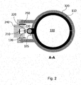
- Fig. 2 shows a cross-sectional view along the cross-sectional line A-A through the piston 330, the sleeve 110, the cylindrical body 320, the magnet 220, and the side cover 240 with the circuit board 250.
- the sleeve 110 extends through a slot 325 of the cylindrical body 320.
- This engagement provides a rotational fixation of the sleeve 110 relative to the cylindrical body 320 so that the sleeve 110 is prevented from rotating relative to the cylindrical body 320.
- the magnet 120 has to remain at the same angular position in Fig. 2 (the axial displacement M is perpendicular to the drawing plane in Fig. 2 ).
- sensor signals generated by the magneto-resistive element 210 remains in the linear operation range (the linearity is maintained).
- the described arrangement provides a stroke sensor based, e.g., on Hall effect technology for the purpose to provide electrical signal proportional to a stroke of the plunger 310.
- the sensor is sensitive to magnetic field variation therefore a permanent magnet 220 is placed near the core element of the sensor (e.g. a Hall chip 210), and properly guided to allow a variation of the magnetic field density once the plunger 310 is actuated. Any other direction of movement of the magnet 220 that differs from the direction of the plunger 310 would cause a deviation in the linearity of the sensor signal.
- the plunger 310 and the piston 330 are sliding inside an upper (cylindrical) body 320 together with the sleeve 110 that act as magnet holder (the sleeve 110 and the mounting 120 can be one integral part).
- the sleeve 110 envelops both the plunger 310 and piston 330 and is open for easy assembly, the opening is opposite oriented with respect to the magnet 220.
- the magnet holder embraces also the cover 130 and slides on it for the complete stroke of the plunger 310.
- the sleeve 110 cannot rotate as the magnet seat (mounting 220) moves inside a slot 325 of the upper body 320.
- the magnet holder is designed to deliver three functions:
Landscapes
- Physics & Mathematics (AREA)
- General Physics & Mathematics (AREA)
- Engineering & Computer Science (AREA)
- General Engineering & Computer Science (AREA)
- Mechanical Engineering (AREA)
- Transportation (AREA)
- Transmission And Conversion Of Sensor Element Output (AREA)
- Measurement Of Length, Angles, Or The Like Using Electric Or Magnetic Means (AREA)
- Regulating Braking Force (AREA)
- Braking Arrangements (AREA)
Claims (12)
- Hubsensor, der einen magnetoresistiven Sensor (210) mit einem Magneten (220) umfasst und ausgelegt ist, eine lineare Verschiebung (M) eines Kolbens (310) in einem zylindrischen Körper (320) einer Kolben-/Zylinderanordnung zu erfassen,wobei der zylindrische Körper (320) einen Innenraum (322) umfasst, in dem die lineare Verschiebung (M) durchgeführt wird, wobei der Hubsensor ferner umfasst einen Magnethalter, der umfasst:- eine Hülse (110), die den Kolben (310) umhüllt;- eine Halterung (120) für den Magneten (220), die radial von der Hülse (110) hervorsteht, wobei sich die Halterung (120) derart radial nach außen von der Hülse (110) erstreckt, dass der Magnet in einer Kammer (230) gehalten ist, die von dem Innenraum (322) separat ist; und- eine Abdeckung (130) zum Verschließen der Hülse (110) auf einer Seite, die eine Öffnung (135) umfasst, um die lineare Verschiebung des Kolbens (310) zu ermöglichen,wobei sich die Hülse (110) und die Abdeckung (130) relativ zueinander bewegen, wenn der Kolben (310) die lineare Verschiebung (M) in dem zylindrischen Körper (320) durchführt.
- Hubsensor nach Anspruch 1, wobei die Kolben-/Zylinderanordnung ferner einen Hubkolben (330) umfasst, der ausgelegt ist, sich zusammen mit dem Kolben (310) in dem zylindrischen Körper (320) zu bewegen,
dadurch gekennzeichnet, dass
die Hülse (110) derart ausgebildet ist, dass sie zumindest einen oberen Abschnitt des Hubkolbens (330) umhüllt. - Hubsensor nach Anspruch 1 oder Anspruch 2, wobei der Kolben (310) in der Lage ist, die lineare Verschiebung und/oder eine Drehung relativ zu dem zylindrischen Körper (320) durchzuführen,
dadurch gekennzeichnet, dass
die Halterung (120) ausgelegt ist, eine Drehverriegelung zwischen der Hülse (110) und dem zylindrischen Körper (320) bereitzustellen, während sie die lineare Verschiebung (M) in dem zylindrischen Körper (320) ermöglicht. - Hubsensor nach Anspruch 2 oder Anspruch 3,
dadurch gekennzeichnet, dass
die Hülse (110) ausgestaltet ist, die lineare Verschiebung zusammen mit dem Kolben (310) und/oder dem Hubkolben (330) durchzuführen. - Hubsensor nach einem der vorhergehenden Ansprüche, wobei der magnetoresistive Sensor (210) mit dem Magneten (220) ein Hallsensor ist.
- Hubsensor nach einem der vorhergehenden Ansprüche,
gekennzeichnet durchdie Kammer (230), die an einem Seitenabschnitt des zylindrischen Körpers (320) angeordnet ist, der von dem Innenraum (322) des zylindrischen Körpers (320) abgedichtet ist; undeine entfernbare Seitenabdeckung (240), die einen Verschluss für die Kammer (230) bereitstellt, wobei der magnetoresistive Sensor (210) zusammen mit seinem Magneten (220) in der Kammer (230) angeordnet ist. - Hubsensor nach einem der vorhergehenden Ansprüche,
gekennzeichnet durch
eine gedruckte Leiterplatte (250), die an der entfernbaren Seitenabdeckung (240) angebracht und ausgestaltet ist, den magnetoresistiven Sensor (210) in der Kammer (230) zu halten. - Hubsensor nach einem der vorhergehenden Ansprüche,
dadurch gekennzeichnet, dass
die Abdeckung (130) ausgestaltet ist, den zylindrischen Körper (320) und die Kammer (230) zu verschließen. - Kolben-/Zylinderanordnung für ein Bremssystem eines Fahrzeugs,
gekennzeichnet durcheinen Kolben (310);einen zylindrischen Körper (320), in dem der Kolben (310) in der Lage ist, eine lineare Verschiebung (M) durchzuführen; undeinen Hubsensor nach einem der vorhergehenden Ansprüche, der ausgelegt ist, ein Sensorsignal basierend auf/in Abhängigkeit von der linearen Verschiebung (M) zu erzeugen. - Kolben-/Zylinderanordnung nach Anspruch 9,
dadurch gekennzeichnet, dass
der zylindrische Körper (320) einen axialen Schlitz (325) zum Aufnehmen eines Teils der Halterung (120) umfasst, um eine axiale Führung für die Hülse (110) bereitzustellen, während relative Drehungen zwischen der Hülse (110) und dem zylindrischen Körper (320) verhindert werden. - Kolben-/Zylinderanordnung nach Anspruch 9 oder Anspruch 10,
gekennzeichnet durcheinen Hubkolben (330), der ausgelegt ist, sich in mindestens eine Richtung zusammen mit dem Kolben (310) in dem zylindrischen Körper (320) zu bewegen, wobei die Hülse (110) ausgestaltet ist, in dem zylindrischen Körper (320) zu gleiten und zumindest einen oberen Abschnitt des Hubkolbens (330) zu umschließen; undeine Dichtung (340) zwischen einem unteren Abschnitt des Hubkolbens (330) und dem zylindrischen Körper (320), um die Kammer (230) von dem Innenraum (322) des zylindrischen Körpers (320) abzudichten. - Fahrzeug mit einer Kolben-/Zylinderanordnung nach einem der Ansprüche 9 bis 11.
Priority Applications (6)
| Application Number | Priority Date | Filing Date | Title |
|---|---|---|---|
| EP18193005.8A EP3620754B1 (de) | 2018-09-06 | 2018-09-06 | Magnethalter und hubsensor mit dem magnethalter |
| CN201980057373.3A CN112639408B (zh) | 2018-09-06 | 2019-08-27 | 磁体保持器和具有磁体保持器的行程传感器 |
| PCT/EP2019/072774 WO2020048818A1 (en) | 2018-09-06 | 2019-08-27 | A magnet holder and stroke sensor with the magnet holder |
| JP2021512625A JP7137000B2 (ja) | 2018-09-06 | 2019-08-27 | 磁石ホルダおよび磁石ホルダを有するストロークセンサ |
| US17/270,790 US12007256B2 (en) | 2018-09-06 | 2019-08-27 | Magnet holder and stroke sensor with the magnet holder |
| BR112021002893-5A BR112021002893B1 (pt) | 2018-09-06 | 2019-08-27 | Sensor de curso, arranjo de êmbolo/cilindro para um sistema de freio de um veículo e veículo |
Applications Claiming Priority (1)
| Application Number | Priority Date | Filing Date | Title |
|---|---|---|---|
| EP18193005.8A EP3620754B1 (de) | 2018-09-06 | 2018-09-06 | Magnethalter und hubsensor mit dem magnethalter |
Publications (2)
| Publication Number | Publication Date |
|---|---|
| EP3620754A1 EP3620754A1 (de) | 2020-03-11 |
| EP3620754B1 true EP3620754B1 (de) | 2022-01-05 |
Family
ID=63524191
Family Applications (1)
| Application Number | Title | Priority Date | Filing Date |
|---|---|---|---|
| EP18193005.8A Active EP3620754B1 (de) | 2018-09-06 | 2018-09-06 | Magnethalter und hubsensor mit dem magnethalter |
Country Status (5)
| Country | Link |
|---|---|
| US (1) | US12007256B2 (de) |
| EP (1) | EP3620754B1 (de) |
| JP (1) | JP7137000B2 (de) |
| CN (1) | CN112639408B (de) |
| WO (1) | WO2020048818A1 (de) |
Families Citing this family (3)
| Publication number | Priority date | Publication date | Assignee | Title |
|---|---|---|---|---|
| WO2021161246A1 (en) * | 2020-02-12 | 2021-08-19 | Padmini Vna Mechatronics Pvt. Ltd. | System for monitoring plunger movement in non-energized condition in real time |
| DE102021109267A1 (de) | 2021-04-14 | 2022-10-20 | Knorr-Bremse Systeme für Nutzfahrzeuge GmbH | Elektromagnetisches Hubmesssystem, Magnethalter sowie Verwendung eines elektromagnetischen Hubmesssystems |
| IT202300011307A1 (it) * | 2023-06-05 | 2024-12-05 | Brembo Spa | Disposizione di magnete lineare per impianti frenanti elettronicamente assistiti |
Citations (20)
| Publication number | Priority date | Publication date | Assignee | Title |
|---|---|---|---|---|
| DE19637296A1 (de) | 1996-09-13 | 1998-03-19 | Wabco Gmbh | Kolben/Zylinder-Anordnung |
| EP1008835A1 (de) | 1998-12-09 | 2000-06-14 | CTS Corporation | Berührungsloses Positionsmessgerät mit sich verjüngenden bipolaren Magneten |
| US20040164611A1 (en) | 2003-02-21 | 2004-08-26 | Olivier Masson | Motor vehicle master cylinder with device for detecting actuation of a braking system |
| DE102006034594A1 (de) | 2006-07-26 | 2008-02-07 | Siemens Ag | Stelleinrichtung, insbesondere Kraftfahrzeug-Feststellbremse |
| US20090261818A1 (en) | 2008-04-18 | 2009-10-22 | Jens-Thorsten Gronau | Position measuring apparatus |
| DE102008052416A1 (de) | 2008-10-21 | 2010-04-22 | Schaeffler Kg | Vorrichtung umfassend ein Betätigungselement eines Zahnräderwechselgetriebes |
| DE102012222547A1 (de) | 2011-12-13 | 2013-06-13 | Continental Teves Ag & Co. Ohg | Vorrichtung zur Überwachung von Position und Bewegung eines Kolbens |
| US20130205881A1 (en) | 2010-07-16 | 2013-08-15 | Lucas Automotive Gmbh | Sensor Module for a Master Cylinder |
| US20140331758A1 (en) | 2013-05-13 | 2014-11-13 | Mando Corporation | Installation structure for pedal stroke sensor |
| US20150033839A1 (en) | 2012-02-14 | 2015-02-05 | Continental Teves Ag & Co. Ohg | Main brake cylinder having a device for the contactless monitoring of the position and movement of a linearly movable piston |
| DE102013015973A1 (de) | 2013-09-25 | 2015-03-26 | Wabco Gmbh | Steuerventilanordnung |
| WO2016012066A1 (de) | 2014-07-23 | 2016-01-28 | Wabco Gmbh | Elektropneumatisches regelventil |
| WO2016041755A1 (de) | 2014-09-19 | 2016-03-24 | Knorr-Bremse Systeme für Nutzfahrzeuge GmbH | Pedaleinrichtung mit seitlich einschiebbarer magnetspulenanordnung |
| US20160144836A1 (en) | 2014-11-20 | 2016-05-26 | Robert Bosch Gmbh | Sensor device, hydraulic unit for cooperating with the sensor device, braking system, and method for installing the sensor device |
| EP3032222A2 (de) | 2014-12-11 | 2016-06-15 | Goodrich Corporation | Kontaktloses lineares positionssensorsystem |
| CN105711566A (zh) | 2015-12-09 | 2016-06-29 | 十堰玄宇汽车电子有限公司 | 电子制动踏板总成 |
| WO2017141725A1 (ja) | 2016-02-16 | 2017-08-24 | 日立オートモティブシステムズ株式会社 | ブレーキ装置、ブレーキシステムおよびマスタシリンダ |
| WO2017190829A1 (de) | 2016-05-04 | 2017-11-09 | Fte Automotive Gmbh | Hydraulikzylinder, insbesondere hauptbremszylinder für hydraulische bremsanlagen |
| US20180162330A1 (en) | 2015-05-29 | 2018-06-14 | Hitachi Automotive Systems, Ltd. | Electric booster and stroke detector |
| KR20180074214A (ko) | 2016-12-23 | 2018-07-03 | 주식회사 인팩 | 전자식 파킹 브레이크용 하중센서 |
Family Cites Families (31)
| Publication number | Priority date | Publication date | Assignee | Title |
|---|---|---|---|---|
| JP3460363B2 (ja) * | 1995-03-02 | 2003-10-27 | 株式会社デンソー | 非接触型位置センサ |
| US6732517B2 (en) | 2002-03-15 | 2004-05-11 | Delphi Technologies, Inc. | Retainer for brake master cylinder travel sensor |
| CN100347015C (zh) | 2003-04-07 | 2007-11-07 | 大陆-特韦斯贸易合伙股份公司及两合公司 | 用于监控制动器踏板的位置和运动的装置 |
| DE102004058875A1 (de) | 2003-12-09 | 2005-08-25 | Continental Teves Ag & Co. Ohg | Verfahren und Vorrichtung zur Regelung eines Kraftfahrzeuges mit einer elektrohydraulischen Bremsanlage mit Fahrdynamikregelung |
| JP2007333122A (ja) * | 2006-06-16 | 2007-12-27 | Kayaba Ind Co Ltd | 油圧シリンダ |
| DE102007036692A1 (de) | 2006-09-22 | 2008-03-27 | Ebm-Papst St. Georgen Gmbh & Co. Kg | Lüfter |
| WO2009073170A2 (en) * | 2007-12-03 | 2009-06-11 | Cts Corporation | Linear position sensor |
| DE102008011615A1 (de) * | 2008-02-28 | 2009-10-29 | Beru Ag | Linearsensor |
| JP5003608B2 (ja) * | 2008-06-20 | 2012-08-15 | トヨタ自動車株式会社 | 車両用制動装置 |
| GB0812903D0 (en) * | 2008-07-15 | 2008-08-20 | Rota Eng Ltd | Linear actuator and position sensing apparatus therefor |
| FR2949737B1 (fr) * | 2009-09-07 | 2011-10-14 | Bosch Gmbh Robert | Systeme de freins a servofrein electrique |
| DE112010004761T5 (de) * | 2009-12-09 | 2012-11-29 | Cts Corporation | Antriebs- und Sensoranordnung |
| JP2014069666A (ja) * | 2012-09-28 | 2014-04-21 | Hitachi Automotive Systems Ltd | 電動倍力装置 |
| CN103802814B (zh) | 2012-11-13 | 2017-05-31 | 博世汽车部件(苏州)有限公司 | 制动助力器 |
| DE102012022519A1 (de) * | 2012-11-16 | 2014-05-22 | Lucas Automotive Gmbh | Hauptbremszylinderanordnung mit Betätigungserfassung für eine Kraftfahrzeugbremsanlage |
| DE102014211146A1 (de) * | 2013-07-03 | 2015-01-08 | Schaeffler Technologies Gmbh & Co. Kg | Kolben-Zylinder-Anordnung, insbesondere für ein Ausrücksystem in einem Kraftfahrzeug |
| WO2015073431A1 (en) * | 2013-11-12 | 2015-05-21 | Cts Corporation | Actuator and linear position sensor assembly |
| TWI695447B (zh) * | 2013-11-13 | 2020-06-01 | 布魯克斯自動機械公司 | 運送設備 |
| JP6213730B2 (ja) * | 2013-11-20 | 2017-10-18 | 日立オートモティブシステムズ株式会社 | ブレーキ装置 |
| JP5945828B2 (ja) * | 2013-12-05 | 2016-07-05 | 日信工業株式会社 | ブレーキシステム用入力装置および車両用ブレーキシステム |
| DE102014207219A1 (de) * | 2014-04-15 | 2015-10-15 | Continental Teves Ag & Co. Ohg | Betätigungseinheit für eine hydraulische Bremsanlage |
| DE102014013942A1 (de) * | 2014-09-19 | 2016-03-24 | Knorr-Bremse Systeme für Nutzfahrzeuge GmbH | Fahrzeugeinrichtung mit stromsparendem Betrieb einer Signaleingabevorrichtung |
| FR3037547B1 (fr) * | 2015-06-22 | 2019-07-05 | Robert Bosch Gmbh | Maitre-cylindre tandem equipe d'un commutateur de feux de stop |
| FR3040957B1 (fr) * | 2015-09-14 | 2017-10-06 | Bosch Gmbh Robert | Systeme d'assistance de freinage |
| KR20170096248A (ko) * | 2016-02-15 | 2017-08-24 | 주식회사 유니크 | 리니어 액추에이터 |
| JP6696811B2 (ja) * | 2016-03-30 | 2020-05-20 | Ntn株式会社 | センサターゲットとこのターゲットを備えた可動部ユニット、並びに電動アクチュエータ |
| JP2018012377A (ja) * | 2016-07-20 | 2018-01-25 | 日立オートモティブシステムズ株式会社 | ブレーキ装置およびマスタシリンダ |
| CN106762960B (zh) * | 2017-02-22 | 2018-09-14 | 中冶华天南京工程技术有限公司 | 一种可改变活塞杆腔作用面积且防活塞旋转液压缸 |
| JP2019132754A (ja) * | 2018-02-01 | 2019-08-08 | アイシン精機株式会社 | センサユニット |
| JP7132838B2 (ja) * | 2018-12-03 | 2022-09-07 | 日立Astemo株式会社 | 自動車用ペダルストローク検出装置および自動車用コントロールユニット |
| DE102020113523A1 (de) * | 2020-05-19 | 2021-11-25 | Knorr-Bremse Systeme für Nutzfahrzeuge GmbH | Gehäuseeinrichtung für eine Bremsvorrichtung für ein Fahrzeug, Stößel für eine Bremsvorrichtung, Bremsvorrichtung mit einer Gehäuseeinrichtung und einem Stößel und Verfahren zum Betreiben einer Bremsvorrichtung |
-
2018
- 2018-09-06 EP EP18193005.8A patent/EP3620754B1/de active Active
-
2019
- 2019-08-27 WO PCT/EP2019/072774 patent/WO2020048818A1/en not_active Ceased
- 2019-08-27 CN CN201980057373.3A patent/CN112639408B/zh active Active
- 2019-08-27 US US17/270,790 patent/US12007256B2/en active Active
- 2019-08-27 JP JP2021512625A patent/JP7137000B2/ja active Active
Patent Citations (21)
| Publication number | Priority date | Publication date | Assignee | Title |
|---|---|---|---|---|
| DE19637296A1 (de) | 1996-09-13 | 1998-03-19 | Wabco Gmbh | Kolben/Zylinder-Anordnung |
| EP1008835A1 (de) | 1998-12-09 | 2000-06-14 | CTS Corporation | Berührungsloses Positionsmessgerät mit sich verjüngenden bipolaren Magneten |
| US20040164611A1 (en) | 2003-02-21 | 2004-08-26 | Olivier Masson | Motor vehicle master cylinder with device for detecting actuation of a braking system |
| DE102006034594A1 (de) | 2006-07-26 | 2008-02-07 | Siemens Ag | Stelleinrichtung, insbesondere Kraftfahrzeug-Feststellbremse |
| US20090261818A1 (en) | 2008-04-18 | 2009-10-22 | Jens-Thorsten Gronau | Position measuring apparatus |
| DE102008052416A1 (de) | 2008-10-21 | 2010-04-22 | Schaeffler Kg | Vorrichtung umfassend ein Betätigungselement eines Zahnräderwechselgetriebes |
| US9266517B2 (en) | 2010-07-16 | 2016-02-23 | Lucas Automotive Gmbh | Sensor module for a master cylinder |
| US20130205881A1 (en) | 2010-07-16 | 2013-08-15 | Lucas Automotive Gmbh | Sensor Module for a Master Cylinder |
| DE102012222547A1 (de) | 2011-12-13 | 2013-06-13 | Continental Teves Ag & Co. Ohg | Vorrichtung zur Überwachung von Position und Bewegung eines Kolbens |
| US20150033839A1 (en) | 2012-02-14 | 2015-02-05 | Continental Teves Ag & Co. Ohg | Main brake cylinder having a device for the contactless monitoring of the position and movement of a linearly movable piston |
| US20140331758A1 (en) | 2013-05-13 | 2014-11-13 | Mando Corporation | Installation structure for pedal stroke sensor |
| DE102013015973A1 (de) | 2013-09-25 | 2015-03-26 | Wabco Gmbh | Steuerventilanordnung |
| WO2016012066A1 (de) | 2014-07-23 | 2016-01-28 | Wabco Gmbh | Elektropneumatisches regelventil |
| WO2016041755A1 (de) | 2014-09-19 | 2016-03-24 | Knorr-Bremse Systeme für Nutzfahrzeuge GmbH | Pedaleinrichtung mit seitlich einschiebbarer magnetspulenanordnung |
| US20160144836A1 (en) | 2014-11-20 | 2016-05-26 | Robert Bosch Gmbh | Sensor device, hydraulic unit for cooperating with the sensor device, braking system, and method for installing the sensor device |
| EP3032222A2 (de) | 2014-12-11 | 2016-06-15 | Goodrich Corporation | Kontaktloses lineares positionssensorsystem |
| US20180162330A1 (en) | 2015-05-29 | 2018-06-14 | Hitachi Automotive Systems, Ltd. | Electric booster and stroke detector |
| CN105711566A (zh) | 2015-12-09 | 2016-06-29 | 十堰玄宇汽车电子有限公司 | 电子制动踏板总成 |
| WO2017141725A1 (ja) | 2016-02-16 | 2017-08-24 | 日立オートモティブシステムズ株式会社 | ブレーキ装置、ブレーキシステムおよびマスタシリンダ |
| WO2017190829A1 (de) | 2016-05-04 | 2017-11-09 | Fte Automotive Gmbh | Hydraulikzylinder, insbesondere hauptbremszylinder für hydraulische bremsanlagen |
| KR20180074214A (ko) | 2016-12-23 | 2018-07-03 | 주식회사 인팩 | 전자식 파킹 브레이크용 하중센서 |
Non-Patent Citations (5)
| Title |
|---|
| ANONYMOUS: "Brake signal Transmitter", WABCO, Retrieved from the Internet <URL:https://www.wabco-customercentre.com/catalog/docs/4800010000_-_605_m_01.tif.pdf> |
| ANONYMOUS: "E G - T Y P G E N E H M I G U N G S B O G E N EC TYPE-APPROVAL CERTIFICAT", KRAFTFAHRT-BUNDESAMT DE-24932 FLENSBURG, 2009, Retrieved from the Internet <URL:https://www.wabco-customercentre.com/catalog/docs/e1-xx3520_076.pdf> |
| ANONYMOUS: "EBS - Elektronisch geregeltes Bremssystem im Reisebus O 580", WABCO SYSTEM- UND FUNKTIONSBESCHREIBUNG, 1 January 1998 (1998-01-01), pages 1 - 14, XP055973360 |
| ANONYMUOS: "EBS Elektronisch geregeltes Bremssystem in Kraftomnibussen System- und Funktionsbeschreibung", WABCO, 1 January 2001 (2001-01-01), pages 1 - 32, XP093154493 |
| ANONYMUOS: "EBS in Motorwagen und Bussen Systembeschreibung", WACBO, 1 January 2016 (2016-01-01), pages 1 - 52, XP093154503 |
Also Published As
| Publication number | Publication date |
|---|---|
| WO2020048818A1 (en) | 2020-03-12 |
| CN112639408B (zh) | 2023-02-03 |
| JP2021536006A (ja) | 2021-12-23 |
| US12007256B2 (en) | 2024-06-11 |
| CN112639408A (zh) | 2021-04-09 |
| BR112021002893A2 (pt) | 2021-05-11 |
| JP7137000B2 (ja) | 2022-09-13 |
| US20210348948A1 (en) | 2021-11-11 |
| EP3620754A1 (de) | 2020-03-11 |
Similar Documents
| Publication | Publication Date | Title |
|---|---|---|
| US10001803B2 (en) | Rotation detection device and a vehicle pedal comprising such a device | |
| EP3620754B1 (de) | Magnethalter und hubsensor mit dem magnethalter | |
| US20150323346A1 (en) | Magnetic Measuring Arrangement and Corresponding Sensor Arrangement for Detecting Motion of a Moving Component | |
| CN101213727B (zh) | 旋转单相电磁伺服执行器 | |
| US20090140730A1 (en) | Linear position sensor | |
| US20140144223A1 (en) | Sensor Module for a Master Cylinder | |
| EP3816599B1 (de) | Magnetisches detektionsmodul, detektionsvorrichtung, gehäuseanordnung und herstellungsverfahren für magnetisches detektionsmodul | |
| KR102607976B1 (ko) | 하중 측정 장치를 갖는 드럼 브레이크 | |
| CN105715789B (zh) | 车辆变速器的切换装置 | |
| US10060759B2 (en) | Rotational angle detecting device and angle sensor unit used therein | |
| US20140320113A1 (en) | Sensor | |
| US20250214556A1 (en) | Brake valve with a magnet holder for a position sensor | |
| US11035696B2 (en) | Sensor arrangement having a modular structure including sensor mounted on bearing element configured to project from housing | |
| EP3006285B1 (de) | Magnetischer schalter | |
| EP4109064B1 (de) | Magnetisches detektionsmodul, detektionsvorrichtung, gehäuseanordnung und herstellungsverfahren für magnetisches detektionsmodul | |
| EP3312564B1 (de) | Vorrichtung zur rotationswinkeldetektion und darin verwendete winkelsensoreinheit | |
| US6711923B2 (en) | Motor vehicle lock | |
| BR112021002893B1 (pt) | Sensor de curso, arranjo de êmbolo/cilindro para um sistema de freio de um veículo e veículo | |
| KR20240091070A (ko) | 제동 장치, 제동 시스템 및 차량 | |
| JP2000171476A (ja) | 電磁ピックアップセンサおよびその製造方法 | |
| KR20250139380A (ko) | 트럭 전용 하우징을 구비한 능동형 센서 | |
| JP2020138686A (ja) | 自動車用ブレーキ制御システム |
Legal Events
| Date | Code | Title | Description |
|---|---|---|---|
| PUAI | Public reference made under article 153(3) epc to a published international application that has entered the european phase |
Free format text: ORIGINAL CODE: 0009012 |
|
| STAA | Information on the status of an ep patent application or granted ep patent |
Free format text: STATUS: THE APPLICATION HAS BEEN PUBLISHED |
|
| AK | Designated contracting states |
Kind code of ref document: A1 Designated state(s): AL AT BE BG CH CY CZ DE DK EE ES FI FR GB GR HR HU IE IS IT LI LT LU LV MC MK MT NL NO PL PT RO RS SE SI SK SM TR |
|
| AX | Request for extension of the european patent |
Extension state: BA ME |
|
| STAA | Information on the status of an ep patent application or granted ep patent |
Free format text: STATUS: REQUEST FOR EXAMINATION WAS MADE |
|
| 17P | Request for examination filed |
Effective date: 20200818 |
|
| RBV | Designated contracting states (corrected) |
Designated state(s): AL AT BE BG CH CY CZ DE DK EE ES FI FR GB GR HR HU IE IS IT LI LT LU LV MC MK MT NL NO PL PT RO RS SE SI SK SM TR |
|
| STAA | Information on the status of an ep patent application or granted ep patent |
Free format text: STATUS: EXAMINATION IS IN PROGRESS |
|
| 17Q | First examination report despatched |
Effective date: 20201127 |
|
| GRAP | Despatch of communication of intention to grant a patent |
Free format text: ORIGINAL CODE: EPIDOSNIGR1 |
|
| STAA | Information on the status of an ep patent application or granted ep patent |
Free format text: STATUS: GRANT OF PATENT IS INTENDED |
|
| INTG | Intention to grant announced |
Effective date: 20210831 |
|
| GRAS | Grant fee paid |
Free format text: ORIGINAL CODE: EPIDOSNIGR3 |
|
| GRAA | (expected) grant |
Free format text: ORIGINAL CODE: 0009210 |
|
| STAA | Information on the status of an ep patent application or granted ep patent |
Free format text: STATUS: THE PATENT HAS BEEN GRANTED |
|
| AK | Designated contracting states |
Kind code of ref document: B1 Designated state(s): AL AT BE BG CH CY CZ DE DK EE ES FI FR GB GR HR HU IE IS IT LI LT LU LV MC MK MT NL NO PL PT RO RS SE SI SK SM TR |
|
| REG | Reference to a national code |
Ref country code: GB Ref legal event code: FG4D |
|
| REG | Reference to a national code |
Ref country code: CH Ref legal event code: EP |
|
| REG | Reference to a national code |
Ref country code: AT Ref legal event code: REF Ref document number: 1460981 Country of ref document: AT Kind code of ref document: T Effective date: 20220115 |
|
| REG | Reference to a national code |
Ref country code: DE Ref legal event code: R096 Ref document number: 602018029020 Country of ref document: DE |
|
| REG | Reference to a national code |
Ref country code: IE Ref legal event code: FG4D |
|
| REG | Reference to a national code |
Ref country code: SE Ref legal event code: TRGR |
|
| REG | Reference to a national code |
Ref country code: LT Ref legal event code: MG9D |
|
| REG | Reference to a national code |
Ref country code: NL Ref legal event code: MP Effective date: 20220105 |
|
| REG | Reference to a national code |
Ref country code: AT Ref legal event code: MK05 Ref document number: 1460981 Country of ref document: AT Kind code of ref document: T Effective date: 20220105 |
|
| PG25 | Lapsed in a contracting state [announced via postgrant information from national office to epo] |
Ref country code: NL Free format text: LAPSE BECAUSE OF FAILURE TO SUBMIT A TRANSLATION OF THE DESCRIPTION OR TO PAY THE FEE WITHIN THE PRESCRIBED TIME-LIMIT Effective date: 20220105 |
|
| PG25 | Lapsed in a contracting state [announced via postgrant information from national office to epo] |
Ref country code: RS Free format text: LAPSE BECAUSE OF FAILURE TO SUBMIT A TRANSLATION OF THE DESCRIPTION OR TO PAY THE FEE WITHIN THE PRESCRIBED TIME-LIMIT Effective date: 20220105 Ref country code: PT Free format text: LAPSE BECAUSE OF FAILURE TO SUBMIT A TRANSLATION OF THE DESCRIPTION OR TO PAY THE FEE WITHIN THE PRESCRIBED TIME-LIMIT Effective date: 20220505 Ref country code: NO Free format text: LAPSE BECAUSE OF FAILURE TO SUBMIT A TRANSLATION OF THE DESCRIPTION OR TO PAY THE FEE WITHIN THE PRESCRIBED TIME-LIMIT Effective date: 20220405 Ref country code: LT Free format text: LAPSE BECAUSE OF FAILURE TO SUBMIT A TRANSLATION OF THE DESCRIPTION OR TO PAY THE FEE WITHIN THE PRESCRIBED TIME-LIMIT Effective date: 20220105 Ref country code: HR Free format text: LAPSE BECAUSE OF FAILURE TO SUBMIT A TRANSLATION OF THE DESCRIPTION OR TO PAY THE FEE WITHIN THE PRESCRIBED TIME-LIMIT Effective date: 20220105 Ref country code: ES Free format text: LAPSE BECAUSE OF FAILURE TO SUBMIT A TRANSLATION OF THE DESCRIPTION OR TO PAY THE FEE WITHIN THE PRESCRIBED TIME-LIMIT Effective date: 20220105 Ref country code: BG Free format text: LAPSE BECAUSE OF FAILURE TO SUBMIT A TRANSLATION OF THE DESCRIPTION OR TO PAY THE FEE WITHIN THE PRESCRIBED TIME-LIMIT Effective date: 20220405 |
|
| PG25 | Lapsed in a contracting state [announced via postgrant information from national office to epo] |
Ref country code: PL Free format text: LAPSE BECAUSE OF FAILURE TO SUBMIT A TRANSLATION OF THE DESCRIPTION OR TO PAY THE FEE WITHIN THE PRESCRIBED TIME-LIMIT Effective date: 20220105 Ref country code: LV Free format text: LAPSE BECAUSE OF FAILURE TO SUBMIT A TRANSLATION OF THE DESCRIPTION OR TO PAY THE FEE WITHIN THE PRESCRIBED TIME-LIMIT Effective date: 20220105 Ref country code: GR Free format text: LAPSE BECAUSE OF FAILURE TO SUBMIT A TRANSLATION OF THE DESCRIPTION OR TO PAY THE FEE WITHIN THE PRESCRIBED TIME-LIMIT Effective date: 20220406 Ref country code: FI Free format text: LAPSE BECAUSE OF FAILURE TO SUBMIT A TRANSLATION OF THE DESCRIPTION OR TO PAY THE FEE WITHIN THE PRESCRIBED TIME-LIMIT Effective date: 20220105 Ref country code: AT Free format text: LAPSE BECAUSE OF FAILURE TO SUBMIT A TRANSLATION OF THE DESCRIPTION OR TO PAY THE FEE WITHIN THE PRESCRIBED TIME-LIMIT Effective date: 20220105 |
|
| PG25 | Lapsed in a contracting state [announced via postgrant information from national office to epo] |
Ref country code: IS Free format text: LAPSE BECAUSE OF FAILURE TO SUBMIT A TRANSLATION OF THE DESCRIPTION OR TO PAY THE FEE WITHIN THE PRESCRIBED TIME-LIMIT Effective date: 20220505 |
|
| REG | Reference to a national code |
Ref country code: DE Ref legal event code: R026 Ref document number: 602018029020 Country of ref document: DE |
|
| PLBI | Opposition filed |
Free format text: ORIGINAL CODE: 0009260 |
|
| PLAX | Notice of opposition and request to file observation + time limit sent |
Free format text: ORIGINAL CODE: EPIDOSNOBS2 |
|
| PG25 | Lapsed in a contracting state [announced via postgrant information from national office to epo] |
Ref country code: SM Free format text: LAPSE BECAUSE OF FAILURE TO SUBMIT A TRANSLATION OF THE DESCRIPTION OR TO PAY THE FEE WITHIN THE PRESCRIBED TIME-LIMIT Effective date: 20220105 Ref country code: SK Free format text: LAPSE BECAUSE OF FAILURE TO SUBMIT A TRANSLATION OF THE DESCRIPTION OR TO PAY THE FEE WITHIN THE PRESCRIBED TIME-LIMIT Effective date: 20220105 Ref country code: RO Free format text: LAPSE BECAUSE OF FAILURE TO SUBMIT A TRANSLATION OF THE DESCRIPTION OR TO PAY THE FEE WITHIN THE PRESCRIBED TIME-LIMIT Effective date: 20220105 Ref country code: EE Free format text: LAPSE BECAUSE OF FAILURE TO SUBMIT A TRANSLATION OF THE DESCRIPTION OR TO PAY THE FEE WITHIN THE PRESCRIBED TIME-LIMIT Effective date: 20220105 Ref country code: DK Free format text: LAPSE BECAUSE OF FAILURE TO SUBMIT A TRANSLATION OF THE DESCRIPTION OR TO PAY THE FEE WITHIN THE PRESCRIBED TIME-LIMIT Effective date: 20220105 Ref country code: CZ Free format text: LAPSE BECAUSE OF FAILURE TO SUBMIT A TRANSLATION OF THE DESCRIPTION OR TO PAY THE FEE WITHIN THE PRESCRIBED TIME-LIMIT Effective date: 20220105 |
|
| 26 | Opposition filed |
Opponent name: ZF CV SYSTEMS EUROPE BV Effective date: 20221005 |
|
| PG25 | Lapsed in a contracting state [announced via postgrant information from national office to epo] |
Ref country code: AL Free format text: LAPSE BECAUSE OF FAILURE TO SUBMIT A TRANSLATION OF THE DESCRIPTION OR TO PAY THE FEE WITHIN THE PRESCRIBED TIME-LIMIT Effective date: 20220105 |
|
| PLBB | Reply of patent proprietor to notice(s) of opposition received |
Free format text: ORIGINAL CODE: EPIDOSNOBS3 |
|
| PG25 | Lapsed in a contracting state [announced via postgrant information from national office to epo] |
Ref country code: SI Free format text: LAPSE BECAUSE OF FAILURE TO SUBMIT A TRANSLATION OF THE DESCRIPTION OR TO PAY THE FEE WITHIN THE PRESCRIBED TIME-LIMIT Effective date: 20220105 |
|
| PG25 | Lapsed in a contracting state [announced via postgrant information from national office to epo] |
Ref country code: MC Free format text: LAPSE BECAUSE OF FAILURE TO SUBMIT A TRANSLATION OF THE DESCRIPTION OR TO PAY THE FEE WITHIN THE PRESCRIBED TIME-LIMIT Effective date: 20220105 |
|
| REG | Reference to a national code |
Ref country code: CH Ref legal event code: PL |
|
| REG | Reference to a national code |
Ref country code: BE Ref legal event code: MM Effective date: 20220930 |
|
| PG25 | Lapsed in a contracting state [announced via postgrant information from national office to epo] |
Ref country code: LU Free format text: LAPSE BECAUSE OF NON-PAYMENT OF DUE FEES Effective date: 20220906 |
|
| P01 | Opt-out of the competence of the unified patent court (upc) registered |
Effective date: 20230528 |
|
| PG25 | Lapsed in a contracting state [announced via postgrant information from national office to epo] |
Ref country code: LI Free format text: LAPSE BECAUSE OF NON-PAYMENT OF DUE FEES Effective date: 20220930 Ref country code: IE Free format text: LAPSE BECAUSE OF NON-PAYMENT OF DUE FEES Effective date: 20220906 Ref country code: CH Free format text: LAPSE BECAUSE OF NON-PAYMENT OF DUE FEES Effective date: 20220930 |
|
| PG25 | Lapsed in a contracting state [announced via postgrant information from national office to epo] |
Ref country code: BE Free format text: LAPSE BECAUSE OF NON-PAYMENT OF DUE FEES Effective date: 20220930 |
|
| PLAB | Opposition data, opponent's data or that of the opponent's representative modified |
Free format text: ORIGINAL CODE: 0009299OPPO |
|
| R26 | Opposition filed (corrected) |
Opponent name: ZF CV SYSTEMS EUROPE BV Effective date: 20221005 |
|
| REG | Reference to a national code |
Ref country code: DE Ref legal event code: R100 Ref document number: 602018029020 Country of ref document: DE |
|
| PG25 | Lapsed in a contracting state [announced via postgrant information from national office to epo] |
Ref country code: HU Free format text: LAPSE BECAUSE OF FAILURE TO SUBMIT A TRANSLATION OF THE DESCRIPTION OR TO PAY THE FEE WITHIN THE PRESCRIBED TIME-LIMIT; INVALID AB INITIO Effective date: 20180906 |
|
| PLCK | Communication despatched that opposition was rejected |
Free format text: ORIGINAL CODE: EPIDOSNREJ1 |
|
| PG25 | Lapsed in a contracting state [announced via postgrant information from national office to epo] |
Ref country code: CY Free format text: LAPSE BECAUSE OF FAILURE TO SUBMIT A TRANSLATION OF THE DESCRIPTION OR TO PAY THE FEE WITHIN THE PRESCRIBED TIME-LIMIT Effective date: 20220105 |
|
| PG25 | Lapsed in a contracting state [announced via postgrant information from national office to epo] |
Ref country code: MK Free format text: LAPSE BECAUSE OF FAILURE TO SUBMIT A TRANSLATION OF THE DESCRIPTION OR TO PAY THE FEE WITHIN THE PRESCRIBED TIME-LIMIT Effective date: 20220105 |
|
| PG25 | Lapsed in a contracting state [announced via postgrant information from national office to epo] |
Ref country code: TR Free format text: LAPSE BECAUSE OF FAILURE TO SUBMIT A TRANSLATION OF THE DESCRIPTION OR TO PAY THE FEE WITHIN THE PRESCRIBED TIME-LIMIT Effective date: 20220105 |
|
| PLBN | Opposition rejected |
Free format text: ORIGINAL CODE: 0009273 |
|
| STAA | Information on the status of an ep patent application or granted ep patent |
Free format text: STATUS: OPPOSITION REJECTED |
|
| 27O | Opposition rejected |
Effective date: 20240305 |
|
| PG25 | Lapsed in a contracting state [announced via postgrant information from national office to epo] |
Ref country code: MT Free format text: LAPSE BECAUSE OF FAILURE TO SUBMIT A TRANSLATION OF THE DESCRIPTION OR TO PAY THE FEE WITHIN THE PRESCRIBED TIME-LIMIT Effective date: 20220105 |
|
| PGFP | Annual fee paid to national office [announced via postgrant information from national office to epo] |
Ref country code: DE Payment date: 20250926 Year of fee payment: 8 |
|
| PGFP | Annual fee paid to national office [announced via postgrant information from national office to epo] |
Ref country code: IT Payment date: 20250919 Year of fee payment: 8 |
|
| PGFP | Annual fee paid to national office [announced via postgrant information from national office to epo] |
Ref country code: GB Payment date: 20250923 Year of fee payment: 8 |
|
| PGFP | Annual fee paid to national office [announced via postgrant information from national office to epo] |
Ref country code: FR Payment date: 20250924 Year of fee payment: 8 |
|
| PGFP | Annual fee paid to national office [announced via postgrant information from national office to epo] |
Ref country code: SE Payment date: 20250924 Year of fee payment: 8 |