EP3619138B1 - Multi-chamber bag - Google Patents
Multi-chamber bag Download PDFInfo
- Publication number
- EP3619138B1 EP3619138B1 EP18840916.3A EP18840916A EP3619138B1 EP 3619138 B1 EP3619138 B1 EP 3619138B1 EP 18840916 A EP18840916 A EP 18840916A EP 3619138 B1 EP3619138 B1 EP 3619138B1
- Authority
- EP
- European Patent Office
- Prior art keywords
- chamber
- storage bag
- pair
- sheets
- sheet
- Prior art date
- Legal status (The legal status is an assumption and is not a legal conclusion. Google has not performed a legal analysis and makes no representation as to the accuracy of the status listed.)
- Active
Links
- 239000000463 material Substances 0.000 claims description 25
- 238000009423 ventilation Methods 0.000 claims description 25
- 239000000853 adhesive Substances 0.000 claims description 23
- 230000001070 adhesive effect Effects 0.000 claims description 23
- 230000007246 mechanism Effects 0.000 claims description 23
- 230000004044 response Effects 0.000 claims description 14
- 239000012530 fluid Substances 0.000 claims description 13
- -1 polypropylene Polymers 0.000 claims description 13
- 239000004743 Polypropylene Substances 0.000 claims description 12
- 229920001155 polypropylene Polymers 0.000 claims description 12
- 238000004891 communication Methods 0.000 claims description 11
- 230000008859 change Effects 0.000 claims description 4
- 229920000728 polyester Polymers 0.000 claims description 2
- 230000002093 peripheral effect Effects 0.000 description 38
- 235000013305 food Nutrition 0.000 description 12
- 238000010438 heat treatment Methods 0.000 description 12
- 238000000034 method Methods 0.000 description 11
- 238000007789 sealing Methods 0.000 description 11
- 244000061456 Solanum tuberosum Species 0.000 description 10
- 235000002595 Solanum tuberosum Nutrition 0.000 description 10
- 235000012015 potatoes Nutrition 0.000 description 10
- 230000007423 decrease Effects 0.000 description 9
- 230000008569 process Effects 0.000 description 7
- 238000010276 construction Methods 0.000 description 6
- 230000000295 complement effect Effects 0.000 description 5
- 238000010411 cooking Methods 0.000 description 5
- 239000004952 Polyamide Substances 0.000 description 3
- 239000004698 Polyethylene Substances 0.000 description 3
- 230000008901 benefit Effects 0.000 description 3
- 239000002131 composite material Substances 0.000 description 3
- 238000010586 diagram Methods 0.000 description 3
- 229920002647 polyamide Polymers 0.000 description 3
- 229920006267 polyester film Polymers 0.000 description 3
- 229920000573 polyethylene Polymers 0.000 description 3
- 235000013599 spices Nutrition 0.000 description 3
- 240000002234 Allium sativum Species 0.000 description 2
- 235000002566 Capsicum Nutrition 0.000 description 2
- 239000006002 Pepper Substances 0.000 description 2
- 241000722363 Piper Species 0.000 description 2
- 235000016761 Piper aduncum Nutrition 0.000 description 2
- 235000017804 Piper guineense Nutrition 0.000 description 2
- 235000008184 Piper nigrum Nutrition 0.000 description 2
- 230000009172 bursting Effects 0.000 description 2
- 235000014121 butter Nutrition 0.000 description 2
- 235000011194 food seasoning agent Nutrition 0.000 description 2
- 235000004611 garlic Nutrition 0.000 description 2
- 235000013310 margarine Nutrition 0.000 description 2
- 239000003264 margarine Substances 0.000 description 2
- 238000004806 packaging method and process Methods 0.000 description 2
- 239000004033 plastic Substances 0.000 description 2
- 229920003023 plastic Polymers 0.000 description 2
- 229920001955 polyphenylene ether Polymers 0.000 description 2
- 238000002360 preparation method Methods 0.000 description 2
- 150000003839 salts Chemical class 0.000 description 2
- 235000002639 sodium chloride Nutrition 0.000 description 2
- XLYOFNOQVPJJNP-UHFFFAOYSA-N water Substances O XLYOFNOQVPJJNP-UHFFFAOYSA-N 0.000 description 2
- 238000003466 welding Methods 0.000 description 2
- 241000251468 Actinopterygii Species 0.000 description 1
- 235000004221 Brassica oleracea var gemmifera Nutrition 0.000 description 1
- 244000308368 Brassica oleracea var. gemmifera Species 0.000 description 1
- 239000004278 EU approved seasoning Substances 0.000 description 1
- 230000009977 dual effect Effects 0.000 description 1
- 235000019688 fish Nutrition 0.000 description 1
- 230000005484 gravity Effects 0.000 description 1
- 239000007788 liquid Substances 0.000 description 1
- 235000013372 meat Nutrition 0.000 description 1
- 238000012986 modification Methods 0.000 description 1
- 230000004048 modification Effects 0.000 description 1
- 235000015067 sauces Nutrition 0.000 description 1
- 238000006467 substitution reaction Methods 0.000 description 1
Images


Classifications
-
- B—PERFORMING OPERATIONS; TRANSPORTING
- B65—CONVEYING; PACKING; STORING; HANDLING THIN OR FILAMENTARY MATERIAL
- B65D—CONTAINERS FOR STORAGE OR TRANSPORT OF ARTICLES OR MATERIALS, e.g. BAGS, BARRELS, BOTTLES, BOXES, CANS, CARTONS, CRATES, DRUMS, JARS, TANKS, HOPPERS, FORWARDING CONTAINERS; ACCESSORIES, CLOSURES, OR FITTINGS THEREFOR; PACKAGING ELEMENTS; PACKAGES
- B65D81/00—Containers, packaging elements, or packages, for contents presenting particular transport or storage problems, or adapted to be used for non-packaging purposes after removal of contents
- B65D81/32—Containers, packaging elements, or packages, for contents presenting particular transport or storage problems, or adapted to be used for non-packaging purposes after removal of contents for packaging two or more different materials which must be maintained separate prior to use in admixture
- B65D81/3261—Flexible containers having several compartments
- B65D81/3266—Flexible containers having several compartments separated by a common rupturable seal, a clip or other removable fastening device
-
- B—PERFORMING OPERATIONS; TRANSPORTING
- B65—CONVEYING; PACKING; STORING; HANDLING THIN OR FILAMENTARY MATERIAL
- B65D—CONTAINERS FOR STORAGE OR TRANSPORT OF ARTICLES OR MATERIALS, e.g. BAGS, BARRELS, BOTTLES, BOXES, CANS, CARTONS, CRATES, DRUMS, JARS, TANKS, HOPPERS, FORWARDING CONTAINERS; ACCESSORIES, CLOSURES, OR FITTINGS THEREFOR; PACKAGING ELEMENTS; PACKAGES
- B65D33/00—Details of, or accessories for, sacks or bags
- B65D33/01—Ventilation or drainage of bags
-
- B—PERFORMING OPERATIONS; TRANSPORTING
- B65—CONVEYING; PACKING; STORING; HANDLING THIN OR FILAMENTARY MATERIAL
- B65D—CONTAINERS FOR STORAGE OR TRANSPORT OF ARTICLES OR MATERIALS, e.g. BAGS, BARRELS, BOTTLES, BOXES, CANS, CARTONS, CRATES, DRUMS, JARS, TANKS, HOPPERS, FORWARDING CONTAINERS; ACCESSORIES, CLOSURES, OR FITTINGS THEREFOR; PACKAGING ELEMENTS; PACKAGES
- B65D33/00—Details of, or accessories for, sacks or bags
- B65D33/16—End- or aperture-closing arrangements or devices
- B65D33/25—Riveting; Dovetailing; Screwing; using press buttons or slide fasteners
- B65D33/2508—Riveting; Dovetailing; Screwing; using press buttons or slide fasteners using slide fasteners with interlocking members having a substantially uniform section throughout the length of the fastener; Sliders therefor
-
- B—PERFORMING OPERATIONS; TRANSPORTING
- B65—CONVEYING; PACKING; STORING; HANDLING THIN OR FILAMENTARY MATERIAL
- B65D—CONTAINERS FOR STORAGE OR TRANSPORT OF ARTICLES OR MATERIALS, e.g. BAGS, BARRELS, BOTTLES, BOXES, CANS, CARTONS, CRATES, DRUMS, JARS, TANKS, HOPPERS, FORWARDING CONTAINERS; ACCESSORIES, CLOSURES, OR FITTINGS THEREFOR; PACKAGING ELEMENTS; PACKAGES
- B65D81/00—Containers, packaging elements, or packages, for contents presenting particular transport or storage problems, or adapted to be used for non-packaging purposes after removal of contents
- B65D81/32—Containers, packaging elements, or packages, for contents presenting particular transport or storage problems, or adapted to be used for non-packaging purposes after removal of contents for packaging two or more different materials which must be maintained separate prior to use in admixture
- B65D81/3261—Flexible containers having several compartments
-
- B—PERFORMING OPERATIONS; TRANSPORTING
- B65—CONVEYING; PACKING; STORING; HANDLING THIN OR FILAMENTARY MATERIAL
- B65D—CONTAINERS FOR STORAGE OR TRANSPORT OF ARTICLES OR MATERIALS, e.g. BAGS, BARRELS, BOTTLES, BOXES, CANS, CARTONS, CRATES, DRUMS, JARS, TANKS, HOPPERS, FORWARDING CONTAINERS; ACCESSORIES, CLOSURES, OR FITTINGS THEREFOR; PACKAGING ELEMENTS; PACKAGES
- B65D81/00—Containers, packaging elements, or packages, for contents presenting particular transport or storage problems, or adapted to be used for non-packaging purposes after removal of contents
- B65D81/34—Containers, packaging elements, or packages, for contents presenting particular transport or storage problems, or adapted to be used for non-packaging purposes after removal of contents for packaging foodstuffs or other articles intended to be cooked or heated within the package
- B65D81/3446—Containers, packaging elements, or packages, for contents presenting particular transport or storage problems, or adapted to be used for non-packaging purposes after removal of contents for packaging foodstuffs or other articles intended to be cooked or heated within the package specially adapted to be heated by microwaves
- B65D81/3461—Flexible containers, e.g. bags, pouches, envelopes
-
- B—PERFORMING OPERATIONS; TRANSPORTING
- B65—CONVEYING; PACKING; STORING; HANDLING THIN OR FILAMENTARY MATERIAL
- B65D—CONTAINERS FOR STORAGE OR TRANSPORT OF ARTICLES OR MATERIALS, e.g. BAGS, BARRELS, BOTTLES, BOXES, CANS, CARTONS, CRATES, DRUMS, JARS, TANKS, HOPPERS, FORWARDING CONTAINERS; ACCESSORIES, CLOSURES, OR FITTINGS THEREFOR; PACKAGING ELEMENTS; PACKAGES
- B65D2205/00—Venting means
- B65D2205/02—Venting holes
-
- B—PERFORMING OPERATIONS; TRANSPORTING
- B65—CONVEYING; PACKING; STORING; HANDLING THIN OR FILAMENTARY MATERIAL
- B65D—CONTAINERS FOR STORAGE OR TRANSPORT OF ARTICLES OR MATERIALS, e.g. BAGS, BARRELS, BOTTLES, BOXES, CANS, CARTONS, CRATES, DRUMS, JARS, TANKS, HOPPERS, FORWARDING CONTAINERS; ACCESSORIES, CLOSURES, OR FITTINGS THEREFOR; PACKAGING ELEMENTS; PACKAGES
- B65D2581/00—Containers, packaging elements, or packages, for contents presenting particular transport or storage problems, or adapted to be used for non-packaging purposes after removal of contents
- B65D2581/34—Containers, packaging elements, or packages, for contents presenting particular transport or storage problems, or adapted to be used for non-packaging purposes after removal of contents for packaging foodstuffs or other articles intended to be cooked or heated within
- B65D2581/3401—Cooking or heating method specially adapted to the contents of the package
- B65D2581/3402—Cooking or heating method specially adapted to the contents of the package characterised by the type of product to be heated or cooked
- B65D2581/3427—Cooking vegetables
-
- B—PERFORMING OPERATIONS; TRANSPORTING
- B65—CONVEYING; PACKING; STORING; HANDLING THIN OR FILAMENTARY MATERIAL
- B65D—CONTAINERS FOR STORAGE OR TRANSPORT OF ARTICLES OR MATERIALS, e.g. BAGS, BARRELS, BOTTLES, BOXES, CANS, CARTONS, CRATES, DRUMS, JARS, TANKS, HOPPERS, FORWARDING CONTAINERS; ACCESSORIES, CLOSURES, OR FITTINGS THEREFOR; PACKAGING ELEMENTS; PACKAGES
- B65D2581/00—Containers, packaging elements, or packages, for contents presenting particular transport or storage problems, or adapted to be used for non-packaging purposes after removal of contents
- B65D2581/34—Containers, packaging elements, or packages, for contents presenting particular transport or storage problems, or adapted to be used for non-packaging purposes after removal of contents for packaging foodstuffs or other articles intended to be cooked or heated within
- B65D2581/3401—Cooking or heating method specially adapted to the contents of the package
- B65D2581/3429—Packages containing a secondary product to be cooked and discharged over the primary product
Definitions
- This disclosure relates to a flexible container, such as a storage bag for food products and the like. More particularly, the present invention relates to a bag having a plurality of chambers separated by a releasable seal and vented for microwave cooking of sealed food products.
- Some storage bags can have a single compartment or chamber in which to store edible goods. Such storage bags can be used for transport and display of various food goods in, for example, a grocery store. However, such goods are only stored in such storage bags. In order to prepare or heat the subject food goods, they must be removed from the storage bags and prepared in a different container before they can be consumed.
- GB2427601A discloses a bag or pouch container for use in cooking foodstuffs in a microwave oven, comprises two sheets of plastics material 8, 9 bonded or welded together along their edges 3 and closed or closable to permit cooking at above atmospheric pressure.
- the sheets are also bonded or welded together along a bonding line or lines 14 extending between edge regions to define compartments 5, 6 within the container for receiving and/or containing foodstuffs or other contents, with said line or lines being separable or rupturable at a desired temperature and/or pressure to permit flow of one foodstuff into the other compartment.
- a pressure relief valve or means 17 is operable to relieve pressure within the container during cooking whilst permitting cooking to continue thereafter at a pressure above atmospheric pressure.
- the sheets 8, 9 may be laminates comprising outer layers 12, 13 of polyester and inner layers 10 of peelable polypropylene and 11 of weldable polypropylene or polyethylene. Compartments 5, 6 may contain meat or fish, and sauce, respectively.
- US2006196784A1 discloses a flexible pouch with multiple compartments for packaging a product includes a wall having an inner surface and an outer surface, and an upper edge, an opposed lower edge and a side edge extending therebetween the upper edge and the lower edge.
- a mid-seam separates the wall into discrete compartments, and the mid-seam is a frangible seal that remains intact when a pressure within the pouch is below a predetermined bursting pressure, and breaks when the pressure within the pouch is greater than the predetermined bursting pressure.
- the pouch also includes an opening means integrally formed in at least one compartment for accessing a product contained within the pouch.
- a method of filling the multi-compartment pouch with a product includes the steps of simultaneously opening each compartment of the pouch using a pair of opposed first grippers positioned on each side edge of the pouch, a pair of opposed second grippers positioned on an upper edge of the pouch, and a pair of opposed suction members positioned on each compartment wall, and simultaneously pushing the first grippers inwardly and second grippers and suction members outwardly.
- the method further includes the steps of filling at least one of the opened compartments with a product applying a closing sealing to seal the filled compartments.
- FR2796047A1 discloses packaging having a supple sheet delimiting a principal enclosure (22) for confining food for preparation (12).
- a weak weld (26) delimits the enclosure into two initially independent chambers (30, 32).
- a principal chamber (30) contains food for preparation and perforations (34) put an auxiliary chamber in contact with air. As temperature rises, pressure in the principal chamber rises and causes the weld to rupture thus putting the two chambers in communication.
- aspects of the present application include a storage bag formed of a film sheet according to the claims appended thereto.
- the film sheet defines a first chamber, a second chamber located adjacent the first chamber; and a releasable seal preventing fluid communication between the first chamber and the second chamber.
- the releasable seal may be configured to release or release when an internal temperature within either the first chamber or the second chamber exceeds a temperature threshold or an internal pressure within either the first chamber or the second chamber exceeds a pressure threshold or upon a desired combination of temperature and pressure being exceeded.
- Patent Body Reference throughout this specification to "one embodiment” or “an embodiment” means that a particular feature, structure, or characteristic described in connection with the embodiment is included in at least one embodiment. Thus, appearances of the phrases “in one embodiment” or “in an embodiment” in various places throughout this specification are not necessarily all referring to the same embodiment. Furthermore, the particular features, structures, or characteristics may be combined in any suitable manner in one or more embodiments.
- FIG. 1 is a graphical depiction of a front view of an embodiment of a storage bag 100.
- the storage bag 100 can have a first chamber 105 and a second chamber 110. When stood upright, the second chamber 110 can be located vertically below the first chamber 105.
- the first chamber 105 may be referred to as the upper chamber 105 and the second chamber 110 may be referred to as the lower chamber 110.
- a releasable seal 115 can be located between the upper chamber 105 and the lower chamber 110.
- the releasable seal 115 may be configured to provide a fluid tight seal between the upper chamber 105 and the lower chamber 110 such that liquid or gas may not pass between the upper chamber 105 and the lower chamber 110 while the releasable seal 115 is closed.
- the upper chamber 105 and the lower chamber 110 can be formed from a single film sheet or from multiple segments of film sheets that are joined together as a single film sheet.
- the releasable seal 115 may include a closure mechanism 145 formed by closure elements 150, 155 located on opposing seal member sheets 160, 165.
- the closure elements 150, 155 can be opposing or complementary sides of a seal to provide the fluid tight seal between the upper chamber 105 and the lower chamber 110.
- the closure elements 150, 155 can form a complementary zipper-like attachment between each other, such as a press-and-lock zipper-style seal (see FIG 4 ).
- the closure elements 150, 155 can be two opposing sides of the storage bag which are adhered to each other, for example using an adhesive (see FIG. 5 ).
- the closure elements 150, 155 can be opposing hook-and-loop style fasteners (see FIG. 6 ).
- the releasable seal 115 provided by the closure elements 150, 155 may be configured to release in response to an internal temperature and/or pressure within the upper chamber 105 and lower chamber 110 exceeding a threshold.
- An exemplary benefit of various embodiments of the releasable seal is the fluid tight seal is maintained until the edible contents of the lower chamber 110 are sufficiently cooked and the (steam) pressure within the lower chamber 110 has built to the point at which the releasable seal 115 is broken, providing fluid communication between the upper chamber 105 and the lower chamber 110. This feature is described in further detail in connection with FIG. 3 through FIG. 6 , below. It is noted that the releasable seal 115 and the closure mechanism 145 of FIG.
- FIG. 1 resembles a zipper style seal, however the disclosure and the closure mechanism 145 are not so limited.
- Other example implementations of the releasable seal 115 are disclosed, for example, in connection with FIG. 3 , FIG. 4, FIG. 5, and FIG. 6 , below.
- the storage bag 100 can include one or more ventilation openings 120.
- the ventilation openings 120 can be apertures or perforations providing fluid communication between an exterior atmosphere 10 surrounding the storage bag 100 and the lower chamber 110 to control pressure within the lower chamber 110.
- the ventilation openings 120 can ensure the releasable seal 115 does not release (e.g., separate, rupture, partially separate or partially rupture) prematurely and that the chamber does not release somewhere other than at the releasable seal.
- the number and size of the ventilation openings 120 may be selected such that during heating of the storage bag 100, the pressure within the lower chamber 110 increases at a particular rate such that edible goods in the upper chamber 105 and the lower chamber 110 are cooked or heated to a desired level prior to the releasable seal 115 rupturing.
- the rate of pressure change within the lower chamber 110 may be affected by the water/steam content of the edible goods in the upper chamber 105 and the lower chamber 110.
- the edible goods are potatoes
- 8 ventilation openings having an average diameter of 1-1.5 mm may provide sufficient ventilation to control release of the releasable seal 115 until the potatoes are sufficiently cooked (approximately 6 minutes into heating).
- the number of the openings can vary, as can their size, in relation to the amount of edible goods.
- a one way or two way gas releasing valve may be used to control and release the pressure.
- the storage bag 100 may be formed from a plurality of sheets 125, 130, 135, 160, 165 of film material joined together by overlapping seals 140, 170, 175, 180 (represented by dotted patterns).
- the seals 140, 170, 175, 180 may be structured to avoid release even during heating of the bag, but may allow tearing or opening by a user after heating has been completed.
- the seals are formed by heat and pressure applied to overlapping portions of the sheets.
- FIG. 2 is a graphical depiction of a pair of sheets 125, 130 that may form the upper chamber 105 of the storage bag 100 of FIG. 1 .
- each sheet 125, 130 may be formed from a composite film material formed from a combination of 12 microns of polyester film and 100 microns of polypropylene.
- example implementations are not limited to these materials and other food safe/microwave safe films (such as orientated polypropylene film, polyamide film, etc.) may be apparent to a person of ordinary skill in the art.
- a two-layer film may provide sufficient mechanical strength maintain to steam pressure during heating.
- other film constructions may be apparent to a person of ordinary skill in the art.
- the sheet 125 includes vertical peripheral regions 205, a lower peripheral region 215 and an upper peripheral region 235 illustrated as the areas outside of the broken line box 220 of FIG. 2 .
- the sheet 130 includes vertical peripheral regions 210, a lower peripheral region 230 and a upper peripheral region 240 illustrated as the areas outside of the broken line box 225 of FIG. 2 .
- the vertical peripheral regions 205 of sheet 125 may be bonded to the vertical regions 210 of the sheet 130 to form part of the vertical seal 195 (represented by a dotted pattern) along edges of the upper chamber 105 ( FIG. 1 ).
- the upper peripheral regions 235, 240 may be bonded together to form the upper seal 140 (represented by a dotted pattern) along the top edge of the upper chamber 105 ( FIG. 1 ). Bonding may be achieved by heat sealing, adhesive application or any other bonding process that might be apparent to a person of ordinary skill in the art.
- FIG. 3 is a graphical depiction of a pair of sheets 160, 165 that may form the releasable seal 115 of the storage bag 100 of FIG. 1 .
- sheets 160, 165 may be formed from a composite film material formed from a combination of 12 microns of polyester film and 100 microns of polypropylene.
- example implementations are not limited to these materials and other food safe/microwave safe films (such as orientated polypropylene film, polyamide film, etc.) can be used.
- a two-layer film may provide sufficient mechanical strength against steam pressure during heating.
- other film constructions may be apparent to a person of ordinary skill in the art.
- the sheet 160 can have vertical peripheral regions 305, a lower peripheral region 335 and an upper peripheral region 315 illustrated as the areas outside of the broken line box 320 of FIG. 3 . Additionally, the sheet 160 can have one or more closure elements 150 that extends from the surface thereof.
- the sheet 165 includes vertical peripheral regions 310, a lower peripheral region 340 and a upper peripheral region 330 illustrated as the areas outside of the broken line box 325 of FIG. 3 . Additionally, the sheet 165 can have one or more closure elements 155 that extend from the surface thereof.
- the vertical peripheral regions 305 of sheet 160 may be bonded to the vertical regions 310 of the sheet 165 to form part of the vertical seal 195 (represented by a dotted pattern) along edges of the releasable seal 115 ( FIG. 1 ). Bonding may be achieved by heat sealing, adhesive application or any other bonding process that might be apparent to a person of ordinary skill in the art.
- FIG. 4 is a cross section of an embodiment of the closure mechanism taken along the line 4 - 4 of FIG. 1 .
- the closure mechanism 145 can be formed as a press-and-lock zipper seal.
- the opposing seal member sheets 160, 165 can have one or more complementary interlocking features implemented as the closure elements 150, 155 of FIG. 3 .
- the closure elements 150, 155 can be implemented as a closure element 156 and a closure element 157 as shown in FIG. 4 .
- the sheet 165 can have closure element 156.
- the closure element 156 can have multiple closure element tabs 152a, 152b.
- the opposing sheet 160 can have at least one closure element 157.
- the closure element 157 can be pressed in between the closure elements 152, for example, in an interference fit. Such an interference fit can provide the releasable seal 115 as described above.
- the shape of the closure elements 156, 157 of FIG. 4 are provided for illustrative purposes. Other profiles and numbers of closure elements 156, 157 may be present to provide the releasable seal 115.
- the closure elements 156, 157 may be formed from a material having a specific rigidity below the threshold temperature but may become sufficiently elastic above the threshold temperature such that the releasable seal may release in response to internal pressure (e.g., within the lower chamber 110) to allow fluid communication between the upper chamber 105 and the lower chamber 110.
- the releasable seal 115 and the closure mechanism 145 is illustrated similar to a zipper in FIG. 1 and FIG. 3 , example implementations of the releasable seal 115 are not limited to a press-and-lock zipper mechanism. In alternative implementations, the releasable seal 115 may be formed by other sealing structures such as those shown in FIG. 5, and FIG. 6 . For example, adhesive regions ( FIG. 5 ), hook and loop regions ( FIG. 6 ), or any other releasable sealing structure that might be apparent to a person of ordinary skill in the art may be substituted for the closure mechanism 145 in example implementations.
- FIG. 5 is a cross section of another embodiment of the closure mechanism taken along the line 4 - 4 of FIG. 1 .
- the closure mechanism 145 e.g., the closure elements 150, 155
- the closure mechanism 145 can be implemented as an adhesive seal.
- the closure mechanism 145 can be implemented using a first adhesive 158 on a sealing location of the inner surface of the storage bag 100.
- a second adhesive 159, opposite the first adhesive can also be used.
- the opposing seal member sheets 160, 165 and the corresponding first adhesive 158 and second adhesive 159 are shown separated from one another for illustrative purposes.
- first adhesive 158 and the second adhesive 159 can be an amount of adhesive, or an adhesive strip along the length of one or both of the opposing sheets 160, 165.
- first adhesive 158 and the second surface 159 of the closure mechanism 145 can be structured to bond with sufficient strength to maintain the releasable seal 115 at pressures below the threshold, but release in response to the internal pressure exceeding the threshold.
- the threshold temperature and/or pressure selected may be within the upper chamber 105 and/or the lower chamber 110.
- the first adhesive 158 and the second surface 159 of the closure mechanism 145 can be structured to soften at elevated temperatures and release the releasable seal 115 at a desired time and temperature.
- a temperature of the releasable seal 115 exceeds a threshold, one of the first adhesive 158 and the second surface 159 of the closure mechanism 145 can soften and release.
- the adhesive material can be selected to respond in the same manner described above to release at the appropriate time and/or in response to determined or selected pressure and temperature levels.
- FIG. 6 is a cross section of another embodiment of the closure mechanism taken along the line 4 - 4 of FIG. 1 .
- the closure mechanism 145 e.g., the closure elements 150, 155
- the closure mechanism 145 can be implemented as a hook-and-loop style closure.
- the sheet 165 can have a loop strip 153 (illustrated as vertical stripes).
- the sheet 160 can then have a hook strip 154 (illustrated as diagonal stripes), complementary to the loop strip 153.
- the loop strip 153 can contact the hook strip 154 can create the releasable seal 115.
- the opposing seal member sheets 160, 165 and corresponding loop strip 153 and hook strip 154 are shown separated from one another for illustrative purposes.
- the releasable seal 115 provided by the closure mechanism 145 as shown in the embodiments of FIG. 4, FIG. 5, and FIG. 6 may be configured to release in response to a combination of an internal temperature and internal pressure within the upper chamber 105 and lower chamber 110 exceeding a threshold.
- a threshold For example, the ability of the releasable seal 115 to withstand internal pressure of the lower chamber 110 decreases as the temperature increases. Therefore, a tradeoff can be made between the temperature and the pressure at which the releasable seal 115 will release.
- FIG. 7 is a graphical representation of sheet 135 that forms the lower chamber 110 of the storage bag 100 of FIG. 1 .
- the sheet 135 may be formed from a composite film material formed from a combination of at least a first layer 166 and a second layer 167 of material as shown in FIG. 4, FIG. 5, and FIG. 6 .
- 12 microns of polyester film and 100 microns of polypropylene In one example, 12 microns of polyester film and 100 microns of polypropylene.
- example implementations are not limited to these materials and other food safe/microwave safe films (such as orientated polypropylene film, polyamide film, etc.) may be apparent to a person of ordinary skill in the art.
- a two-layer film may provide sufficient mechanical strength maintain to steam pressure during heating.
- the sheet 135 can have one or more layers.
- the inner-most layer forming the layer that lines the interior of the upper chamber 105 and the lower chamber 110 can be a material joinable using heat or ultrasonic signals (e.g., weldable) such as polypropylene (PP), polyethylene (PE), or polyphenylene ether (PPE) plastic, for example.
- PP polypropylene
- PE polyethylene
- PPE polyphenylene ether
- the thickness of the various layers of the material in the sheet 135 can be based on application and demand for strength.
- the bag 100 designed to contain 50 pounds of potatoes may require a more robust structure than 12 ounces of Brussels sprouts.
- the sheet 135 includes vertical peripheral regions 405, a first horizontal peripheral region 410 and a second horizontal peripheral region 415 illustrated as the areas outside of the broken line box 420 of FIG. 7 .
- the sheet 135 may also include a plurality of ventilation openings 120.
- the ventilation openings 120 can be arranged in one or more rows spaced apart.
- the sheet 135 also includes a gusset region 425 that may be disposed between the rows of ventilation openings 120.
- the number and size of the ventilation openings 120 may be selected such that during heating of the storage bag 100, the pressure within the lower chamber 110 increases at a particular rate such that edible goods in the upper chamber 105 and the lower chamber 110 is substantially cooked prior to the releasable seal 115 rupturing.
- the rate of pressure change within the lower chamber 110 may be affected by the water/steam content of the edible goods in the upper chamber 105 and the lower chamber 110. For example, if the edible goods are potatoes, eight (8) ventilation openings having an average diameter of 1-1.5 mm may provide sufficient ventilation to control release of the releasable seal 115 until the potatoes are sufficiently cooked (approximately 6 minutes into heating).
- the gusset region 425 includes a plurality of folds spanning a width of the sheet 135, across the sheet 135.
- the folds are represented by broken lines (folds) 430, 432.
- the folds 430, 432 can be formed in a direction parallel to the one or more ventilation openings 120.
- the gusset region 425 can also have a plurality of seams represented by broken lines 435, 440, 445, 450 adjacent the folds represented by broken lines 432.
- the seams can be formed by sealing or otherwise welding adjacent pairs of the broken lines 435, 440, 445, 450 together. The resulting seams can then lie at either end (first end opposite a second end) of the folds 430, 432.
- the gusset region 425 is folded along each of the broken lines 430, 432. Specifically, the gusset region 425 is folded in a first direction along broken line 430 and folded in a second, different direct along broken line 432.
- the first direction can be parallel to the first horizontal peripheral region 410 and the second peripheral region 415.
- the second direction can be at an angle to the first direction as shown in FIG. 7 .
- the folds 430, 432 (first direction) can lie at approximately a 45 degree angle to the seams between adjacent pairs of the broken lines 435, 440, 445, 450, when assembled. Additionally, each of the seams represented by broken lines 435 may be bonded together.
- each of the seams represented by broken lines 440 may be bonded together. Additionally, each of the seams represented by broken lines 445 may be bonded together. Each of the seams represented by broken lines 450 may also be bonded together. Additionally, once folded along the broken lines 430, the vertical peripheral region 405 of each side of the sheet 135 may be bonded to itself to form part of the vertical seal 195 (represented by a dotted pattern) along edges of the lower chamber 110 in FIG. 1 . Once folded and bonded, the gusset region 425 may allow the bag 100 to free stand. Bonding may be achieved by heat sealing, adhesive application or any other bonding or welding process that might be apparent to a person of ordinary skill in the art.
- FIG. 8 is a graphical depiction of the sheet 125 of FIG. 1 .
- the sheet 125 can form a portion (e.g., half) of the upper chamber 105 of the storage bag 100 ( FIG. 1 ) when bonded to the sheet 130 and the sheets 165 that forms the releasable seal 115.
- FIG. 9 is a graphical depiction of the sheet 130 of FIG. 1 .
- the sheet 130 can form a portion of the upper chamber 105 when bonded to the sheet 125 and the sheets 160 that forms the releasable seal 115.
- the upper chamber 105 is then completely formed when the sheets 125, 130 are bonded to one of the sheets 160, 165 that form the releasable seal 115 in accordance with example implementations of the present application.
- the upper peripheral region 330 of sheet 165 has been bonded to the lower peripheral region 215 of sheet 125 to form a seal 170 (represented by a dotted pattern).
- the upper peripheral region 315 of sheet 160 has been bonded to the lower peripheral region 230 to form a seal 185 (represented by a dotted pattern). Bonding may be achieved by heat sealing, adhesive application or any other bonding process that might be apparent to a person of ordinary skill in the art.
- FIG. 10 is a graphical representation of an alternative construction of the bag of FIG. 1 , which is not covered by the appended claims.
- the bag 100 ( FIG. 1 ) can be formed from a single sheet 700 of film material.
- the film material can also be referred to herein as a film sheet, comprising the single sheet 700.
- the sheets 125, 130, 135 described above in connection with FIG. 2 through FIG. 9 may be replaced by analogous regions or sections 125, 130, 135 of the single sheet 700.
- identical reference numbers have been used to refer to analogous aspects of the sheets 125, 130, 135 of the single sheet 700.
- the upper first horizontal peripheral region 410 of the sheet 135 is integral with (or has been bonded to) the lower peripheral region of sheet 165 forms part of the releasable seal 115, to form the seal 175 (represented by a dotted pattern).
- the upper peripheral region 330 of sheet 165 that forms part of the releasable seal 115 is integral with (or has been bonded to) a lower peripheral region 215 of sheet 125 that forms part of the upper chamber 105 to form a seal 170 (represented by a dotted pattern).
- the sheet 160 that forms part of the releasable seal 115 in FIG. 1 may be rotated 180° such that the lower or second peripheral region 415 of sheet 135 may be bonded to the lower peripheral region 335 of sheet 160 to form a seal 190 (represented by a dotted pattern).
- the upper peripheral region 315 of sheet 160 of the releasable seal 115 ( FIG. 1 ) is integral with (or is bonded to) a lower peripheral 230 of sheet 130 that forms part of the upper chamber 105 to form a seal 185 (represented by a dotted pattern).
- the vertical peripheral regions 205 of sheet 125 may be integral with (or bonded to) the vertical regions 210 of sheet 130 to form part of the vertical seal 195 (represented by a dotted pattern of FIG. 1 ) along edges of the upper chamber 105.
- the vertical peripheral regions 305 of sheet 160 may be bonded to the vertical regions 310 of sheet 165 to form part of the vertical seal 195 (represented by a dotted pattern) along edges of the releasable seal 115 in FIG. 1 .
- the gusset region 425 includes a plurality of folds represented by broken lines 430, 432 and a plurality of seams represented by broken lines 435, 440, 445, 450 adjacent the folds represented by broken lines 432.
- the gusset region 425 is folded along each of the broken lines 430, 432.
- the gusset region 425 is folded in a first direction along broken line 430 and folded in a second, different (e.g., opposite) direction along broken line 432.
- each of the seams represented by broken lines 435 may be bonded together.
- each of the seams represented by broken lines 440 may be bonded together.
- each of the seams represented by broken lines 445 may be bonded together.
- Each of the seams represented by broken lines 450 may also be bonded together. Additionally, once folded along the broken lines 430, the vertical peripheral region 405 of each side of the sheet 135 may be bonded to itself to form part of the vertical seal 195 (represented by a dotted pattern) along edges of the lower chamber 110 in FIG. 1 . Once folded and bonded, the gusset region 425 may allow the bag 100 to free stand. Bonding may be achieved by heat sealing, adhesive application or any other bonding process that might be apparent to a person of ordinary skill in the art.
- the vertical peripheral region 405 of each side of the sheet section may be bonded to itself to form part of the vertical seal 195 (represented by a dotted pattern) along edges of the lower chamber 110 in FIG. 1 .
- the gusset region 425 may allow the bag 100 to free stand.
- the upper peripheral regions 235, 240 of sheets 205, 210 may be bonded together to form the upper seal 140 (represented by a dotted pattern) along the top edge of the upper chamber 105 in FIG. 1 . Bonding may be achieved by heat sealing, adhesive application or any other bonding process that might be apparent to a person of ordinary skill in the art.
- FIG. 2 through FIG. 9 illustrate the bag 100 being formed from five individual sheets 125, 130, 135, 160, 165 of film bonded together
- example implementations are not limited to this configuration.
- the bag 100 can be formed from a single sheet of film, as described above in connection with FIG. 10 .
- FIG. 8 and FIG. 9 illustrate the sheets 160, 165 that form the releasable seal 115 first being bonded to the sheets 125, 130 that form the upper chamber 105, and then bonded to the sheet 135 that forms the lower chamber 110
- example implementations are not limited to this configuration.
- Other example implementations may be formed by first bonding the sheets 160, 165 to the sheet 135, or any other arrangement that might be apparent to a person of ordinary skill in the art.
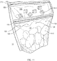
- FIG. 11 is a perspective view of a bag 100 of FIG. 1 .
- the bag 100 can be used with various types of edible goods 815, 820 provided in the upper chamber 105 and in the lower chamber 110.
- a first type of edible goods 810 e.g., butter, margarine, salt, pepper, garlic, spices, etc., alone or in combination
- a second type of edible goods 815 e.g., potatoes
- the releasable seal 115 may keep the first type of edible goods 810 separate from the second type of edible goods 815 for transport, storage, etc.
- a plurality of ventilation openings 120 are provided in the bag 100 to allow fluid communication between the interior of the lower chamber 110 and the atmosphere 10 surrounding the bag.
- the upper edge 805 of the bag 100 may be a tear away portion to allow the bag 100 to be opened.
- a notch 816 may be present enabling the upper edge 805 of the upper chamber 105 to be torn away.
- the bag 100 can have one or more notches 816.
- the bag 100 may be heated (e.g., using a microwave oven or other heating source). As bag 100 is heated, each of the first type of edible goods 810 and the second type of edible goods 815 are separately heated in their respective upper chamber 105 and lower chamber 110. In some embodiments, as each of the first type of edible goods 810 and the second type of edible goods 815 are heated, steam or other gaseous food material may build up in the upper chamber 105 and the lower chamber 110, increasing internal pressure within. As the internal pressure increases in the upper chamber 105 and the lower chamber 110, the stress created by the increased pressure may be applied to releasable seal 115.
- the releasable seal 115 When the pressures within the upper chamber 105 and the lower chamber 110 exceed a threshold, the releasable seal 115 will release and gravity may pull the first type of edible goods 810 toward the second type of edible goods 815 mixing the two types of edible goods 810, 815.
- the releasable seal 115 may be configured to release in response to an internal temperature within the upper chamber 105 and lower chamber 110 exceeding a threshold.
- releasable seal 115 may be formed from a material having a specific rigidity below the threshold temperature but may become sufficiently elastic above the threshold temperature. The elasticity can be such that the releasable seal releases or opens in response to internal pressure to allow fluid communication between the upper chamber 105 and the lower chamber 110. This can allow the first type of edible goods 810 to mix with the second type of edible goods 815
- the releasable seal 115 may be configured to release in response to a combination of an internal temperature and internal pressure within the upper chamber 105 and lower chamber 110 exceeding a threshold.
- the releasable seal 115 may be formed from a material having a rigidity that decreases in response increasing temperature. As the rigidity decreases (the material becomes more elastic) the adhesion of the seal decreases. The ability of the seal to withstand internal pressure decreases as the temperature increases. Therefore, a tradeoff can be made between the temperature and the pressure at which the releasable seal will release.
- the openings 120 providing fluid communication between the exterior atmosphere 10 surrounding the storage bag 100 and the lower chamber 110 allow control of the pressure within the lower chamber 110 to ensure the releasable seal 115 does not release prematurely (e.g., before the first type of edible goods 810 and the second type of edible goods 815 are sufficiently cooked).
- the openings 120 can further ensure that the lower chamber 110 does not release somewhere other than at the releasable seal.
- the number and size of the ventilation openings 120 may be selected such that during heating of the storage bag 100, the pressure within the lower chamber 110 increases at a particular rate such that edible goods in the upper chamber 105 and the lower chamber 110 are substantially cooked prior to the releasable seal 115 rupturing.
- the second type of edible goods 815 being potatoes
- eight (8) ventilation openings having an average diameter of 1-1.5 mm may provide sufficient ventilation to control release of the releasable seal 115 until the potatoes are sufficiently cooked (approximately 6 minutes).
- the number of the openings can vary, as can their size, in relation to the amount of edible goods.
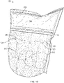
- FIG. 12 is another perspective view of the bag of FIG. 1 .
- the bag 100 is shown with the first type of edible goods 810 and the second type of edible goods 815 after heating. As illustrated, releasable seal 115 has released and the first type of edible goods 810 (e.g., butter, margarine, salt, pepper, garlic, spices, etc., alone or in combination) has mixed or coated the second type of edible goods 815 (e.g., potatoes) in the lower chamber 110.
- the bag 100 is shown inflated due to, for example, the release of steam and other vapors from the cooked second type of edible goods 815.
- the first type of edible goods 810 is shown dispersed about the second type of edible goods 815 and is depicted as scattered circles and triangles representing, for example, spices or other seasonings.
- pressure may increase in only one of the upper chamber 105 and the lower chamber 110.
- the first type of edible foods 810 is a seasoning, it may not produce an appreciable amount of steam or other gaseous food when heated. Therefore, the increased pressure that releases the releasable seal 115 may originate in (predominantly) the lower chamber 110, as for example, the second edible goods 815 produces steam as it cooks.
- the releasable seal 115 may be configured to release in response to an internal temperature within the upper chamber 105 and lower chamber 110 exceeding a threshold.
- releasable seal 115 may be formed from a material having a specific rigidity below the threshold temperature but may become sufficiently elastic above the threshold temperature such that the releasable seal may release in response to internal pressure to allow fluid communication between the upper chamber 105 and the lower chamber 110.
- the releasable seal 115 may be configured to release in response to a combination of an internal temperature and internal pressure within the upper chamber 105 and lower chamber 110 exceeding a threshold.
- the releasable seal 115 may be formed from a material having a rigidity that decreases in response increasing temperature. As the rigidity decreases (the material becomes more elastic) the adhesion of the seal decreases. The ability of the seal to withstand internal pressure decreases as the temperature increases. Therefore, a tradeoff can be made between the temperature and the pressure at which the releasable seal will release.
- the bag 100 may now be opened and the combination of the first type of edible goods 810 and the second type of edible goods 815 may be consumed.
- the upper edge 805 of the bag 100 may be torn away to allow the bag 100 to be opened.
- Other mechanisms for opening the bag 100 may be apparent to a person of ordinary skill in the art.
- potatoes are illustrated as the second type of edible goods 815 in FIG. 8 and FIG. 9 , example implementations are not limited to these edible goods and other edible goods may be apparent to a person of ordinary skill in the art.
Landscapes
- Engineering & Computer Science (AREA)
- Mechanical Engineering (AREA)
- Life Sciences & Earth Sciences (AREA)
- Food Science & Technology (AREA)
- Bag Frames (AREA)
- Supplying Of Containers To The Packaging Station (AREA)
- External Artificial Organs (AREA)
- Packages (AREA)
Applications Claiming Priority (2)
| Application Number | Priority Date | Filing Date | Title |
|---|---|---|---|
| US201762540500P | 2017-08-02 | 2017-08-02 | |
| PCT/US2018/044833 WO2019028154A1 (en) | 2017-08-02 | 2018-08-01 | MULTI-ROOM BAG |
Publications (3)
| Publication Number | Publication Date |
|---|---|
| EP3619138A1 EP3619138A1 (en) | 2020-03-11 |
| EP3619138A4 EP3619138A4 (en) | 2021-04-21 |
| EP3619138B1 true EP3619138B1 (en) | 2022-10-26 |
Family
ID=65231503
Family Applications (1)
| Application Number | Title | Priority Date | Filing Date |
|---|---|---|---|
| EP18840916.3A Active EP3619138B1 (en) | 2017-08-02 | 2018-08-01 | Multi-chamber bag |
Country Status (11)
| Country | Link |
|---|---|
| US (1) | US10710789B2 (pt) |
| EP (1) | EP3619138B1 (pt) |
| CN (1) | CN111032531A (pt) |
| AU (1) | AU2018312548B2 (pt) |
| CA (1) | CA3071400A1 (pt) |
| DK (1) | DK3619138T3 (pt) |
| ES (1) | ES2932092T3 (pt) |
| MX (1) | MX2020001186A (pt) |
| PT (1) | PT3619138T (pt) |
| RU (1) | RU2741498C1 (pt) |
| WO (1) | WO2019028154A1 (pt) |
Families Citing this family (7)
| Publication number | Priority date | Publication date | Assignee | Title |
|---|---|---|---|---|
| CN111907905B (zh) | 2019-05-10 | 2023-08-04 | 特克逊国际有限公司 | 袋及相关方法 |
| US11629001B2 (en) * | 2019-05-22 | 2023-04-18 | Krunchy Wrap, Llc | Wrapper and three-dimensional package with steam venting feature for hot food items and method |
| CN115916660A (zh) * | 2020-06-30 | 2023-04-04 | 京洛株式会社 | 包装袋 |
| KR102687219B1 (ko) | 2021-01-12 | 2024-07-22 | 인스턴트 브랜즈 홀딩스 인크. | 실리콘 식품 및 음료 저장 용기들 |
| USD1022604S1 (en) | 2022-01-11 | 2024-04-16 | Instant Brands Holdings Inc. | Combined food and beverage storage container |
| USD1022606S1 (en) | 2022-01-11 | 2024-04-16 | Instant Brands Holdings Inc. | Combined food and beverage storage container |
| USD1022605S1 (en) | 2022-01-11 | 2024-04-16 | Instant Brands Holdings Inc. | Combined food and beverage storage container |
Family Cites Families (22)
| Publication number | Priority date | Publication date | Assignee | Title |
|---|---|---|---|---|
| US4806371A (en) * | 1986-11-10 | 1989-02-21 | Packageing Concepts, Inc. | Microwavable package for packaging combination of products and ingredients |
| SE9601348D0 (sv) * | 1996-04-10 | 1996-04-10 | Pharmacia Ab | Improved containers for parenteral fluids |
| JP3605306B2 (ja) * | 1998-12-22 | 2004-12-22 | 株式会社サンエー化研 | 加熱処理用包装体および包装体 |
| FR2796047B1 (fr) * | 1999-07-06 | 2001-09-21 | Danisco Flexible France | Emballage pour le conditionnement d'une preparation alimentaire |
| US6254907B1 (en) * | 1999-12-21 | 2001-07-03 | Fres-Co System Usa, Inc. | Bowl bag with resealable closure means |
| US20060196784A1 (en) * | 2005-03-03 | 2006-09-07 | Murray R C | Multi-compartment flexible pouch |
| EP1894851B1 (en) * | 2005-06-15 | 2012-02-01 | Fujimori Kogyo Co., Ltd. | Duplex-chamber package |
| GB0512889D0 (en) * | 2005-06-24 | 2005-08-03 | Steamfast Europ Ltd | Improvement in or relating to containers for cooking foodstuffs |
| US8398306B2 (en) * | 2005-11-07 | 2013-03-19 | Kraft Foods Global Brands Llc | Flexible package with internal, resealable closure feature |
| GB2449288A (en) * | 2007-05-18 | 2008-11-19 | Elizabeth Johnson | Pouch container with two compartments separated by a fluid-tight weak bond |
| US20090117323A1 (en) * | 2007-11-05 | 2009-05-07 | David Lin | Airtight Self-venting Composite Film for Food Packaging |
| US20090142006A1 (en) | 2007-11-30 | 2009-06-04 | N.S. Flexibles, Llc | Multicompartment bag having resealable opposed openings |
| US20090257685A1 (en) * | 2008-04-14 | 2009-10-15 | Illinois Tool Works Inc. | Flexible storage bag with vent between two zipper |
| US20100142862A1 (en) * | 2008-12-05 | 2010-06-10 | Bassam Abed Sam | Container bag with multiple sealable locks |
| DE102009018489A1 (de) * | 2009-04-22 | 2010-10-28 | Huhtamaki Ronsberg, Zweigniederlassung Der Huhtamaki Deutschland Gmbh & Co. Kg | Verpackung, insbesondere Mikrowellen-Verpackungsbeutel, mit Druckausgleichsventil mit variablen Strömungsquerschnitt |
| US9395251B2 (en) * | 2009-09-30 | 2016-07-19 | Imagineering, Inc. | Temperature sensitive body, optical temperature sensor, temperature measurement device, and heat flux measurement |
| JP5840387B2 (ja) * | 2011-06-01 | 2016-01-06 | 株式会社サンエー化研 | 加熱処理用包装体及びそれに食材が収納された包装食品 |
| EP2847095B1 (en) * | 2012-05-10 | 2018-11-21 | Ampac Holdings LLC | Multi-compartment pouch with breakable inner compartment |
| ITMI20130977A1 (it) * | 2013-06-13 | 2014-12-14 | Goglio Spa | Confezione in materiale flessibile per prodotti alimentari da consumare dopo riscaldamento in forno |
| GB2516695A (en) * | 2013-07-30 | 2015-02-04 | Parkside Flexibles Europ Ltd | Package |
| CA2883975A1 (en) * | 2015-03-05 | 2016-09-05 | P.E.I. Mussel King (1994) Inc. | Cook-in, stand up pouch for live shellfish |
| GB2546782A (en) * | 2016-01-28 | 2017-08-02 | Parkside Flexibles (Europe) Ltd | Package |
-
2018
- 2018-08-01 ES ES18840916T patent/ES2932092T3/es active Active
- 2018-08-01 CN CN201880049008.3A patent/CN111032531A/zh active Pending
- 2018-08-01 MX MX2020001186A patent/MX2020001186A/es unknown
- 2018-08-01 DK DK18840916.3T patent/DK3619138T3/da active
- 2018-08-01 WO PCT/US2018/044833 patent/WO2019028154A1/en unknown
- 2018-08-01 PT PT188409163T patent/PT3619138T/pt unknown
- 2018-08-01 US US16/052,398 patent/US10710789B2/en active Active
- 2018-08-01 AU AU2018312548A patent/AU2018312548B2/en active Active
- 2018-08-01 EP EP18840916.3A patent/EP3619138B1/en active Active
- 2018-08-01 RU RU2019140002A patent/RU2741498C1/ru active
- 2018-08-01 CA CA3071400A patent/CA3071400A1/en active Pending
Also Published As
| Publication number | Publication date |
|---|---|
| AU2018312548A1 (en) | 2020-01-02 |
| ES2932092T3 (es) | 2023-01-11 |
| MX2020001186A (es) | 2021-09-07 |
| NZ759894A (en) | 2021-04-30 |
| WO2019028154A1 (en) | 2019-02-07 |
| CA3071400A1 (en) | 2019-02-07 |
| CN111032531A (zh) | 2020-04-17 |
| EP3619138A4 (en) | 2021-04-21 |
| PT3619138T (pt) | 2022-11-16 |
| US20190039805A1 (en) | 2019-02-07 |
| DK3619138T3 (da) | 2022-11-14 |
| EP3619138A1 (en) | 2020-03-11 |
| AU2018312548B2 (en) | 2020-12-10 |
| RU2741498C1 (ru) | 2021-01-26 |
| US10710789B2 (en) | 2020-07-14 |
Similar Documents
| Publication | Publication Date | Title |
|---|---|---|
| EP3619138B1 (en) | Multi-chamber bag | |
| US20100159083A1 (en) | Container for cooking foodstuffs and method of manufacturing the same | |
| TWI786041B (zh) | 夾鏈帶、袋體、及袋體之製造方法 | |
| EP1721833A1 (en) | Self-venting reclosable packages | |
| US20090045189A1 (en) | Microwaveable package | |
| EP1928762B1 (en) | A packaging having an improved reclosable opening | |
| CN110088007B (zh) | 具有喷口储器/保持特征的包装 | |
| JP7530912B2 (ja) | 袋及び関連する方法 | |
| JP2009166847A (ja) | 包装袋 | |
| JP5118979B2 (ja) | 包装袋 | |
| JP2009012831A (ja) | 包装袋 | |
| US20220234810A1 (en) | Plastic film and packaging using the plastic film | |
| JP6753159B2 (ja) | 電子レンジ加熱用包装袋 | |
| NZ759894B2 (en) | Multi-chamber bag | |
| JP2008296968A (ja) | 包装袋 | |
| JP7532853B2 (ja) | パウチ | |
| WO2020262614A1 (ja) | 冷凍食品入り袋製品 | |
| WO2016138591A1 (en) | Cook-in, stand up pouch for live shellfish | |
| JP2022053213A (ja) | チャック付きの電子レンジ用の袋 | |
| JPH09221151A (ja) | 包装袋 | |
| JP2007008501A5 (pt) | ||
| JP2007008501A (ja) | 電子レンジ加熱可能な自立袋とその包装体並びに該自立袋の作製方法 | |
| JP2006151411A (ja) | 蒸気抜き付レトルトパウチ | |
| CA2443619A1 (en) | Resealable bag with arcuate rupturable seal |
Legal Events
| Date | Code | Title | Description |
|---|---|---|---|
| STAA | Information on the status of an ep patent application or granted ep patent |
Free format text: STATUS: THE INTERNATIONAL PUBLICATION HAS BEEN MADE |
|
| PUAI | Public reference made under article 153(3) epc to a published international application that has entered the european phase |
Free format text: ORIGINAL CODE: 0009012 |
|
| STAA | Information on the status of an ep patent application or granted ep patent |
Free format text: STATUS: REQUEST FOR EXAMINATION WAS MADE |
|
| 17P | Request for examination filed |
Effective date: 20191205 |
|
| AK | Designated contracting states |
Kind code of ref document: A1 Designated state(s): AL AT BE BG CH CY CZ DE DK EE ES FI FR GB GR HR HU IE IS IT LI LT LU LV MC MK MT NL NO PL PT RO RS SE SI SK SM TR |
|
| AX | Request for extension of the european patent |
Extension state: BA ME |
|
| DAV | Request for validation of the european patent (deleted) | ||
| DAX | Request for extension of the european patent (deleted) | ||
| A4 | Supplementary search report drawn up and despatched |
Effective date: 20210318 |
|
| RIC1 | Information provided on ipc code assigned before grant |
Ipc: B65D 81/32 20060101AFI20210312BHEP Ipc: B65D 33/01 20060101ALI20210312BHEP Ipc: B65D 33/25 20060101ALI20210312BHEP Ipc: B65D 75/30 20060101ALI20210312BHEP Ipc: B65D 81/34 20060101ALI20210312BHEP |
|
| GRAP | Despatch of communication of intention to grant a patent |
Free format text: ORIGINAL CODE: EPIDOSNIGR1 |
|
| STAA | Information on the status of an ep patent application or granted ep patent |
Free format text: STATUS: GRANT OF PATENT IS INTENDED |
|
| RIC1 | Information provided on ipc code assigned before grant |
Ipc: B65D 81/34 20060101ALI20220419BHEP Ipc: B65D 75/30 20060101ALI20220419BHEP Ipc: B65D 33/25 20060101ALI20220419BHEP Ipc: B65D 33/01 20060101ALI20220419BHEP Ipc: B65D 81/32 20060101AFI20220419BHEP |
|
| INTG | Intention to grant announced |
Effective date: 20220518 |
|
| GRAS | Grant fee paid |
Free format text: ORIGINAL CODE: EPIDOSNIGR3 |
|
| GRAA | (expected) grant |
Free format text: ORIGINAL CODE: 0009210 |
|
| STAA | Information on the status of an ep patent application or granted ep patent |
Free format text: STATUS: THE PATENT HAS BEEN GRANTED |
|
| AK | Designated contracting states |
Kind code of ref document: B1 Designated state(s): AL AT BE BG CH CY CZ DE DK EE ES FI FR GB GR HR HU IE IS IT LI LT LU LV MC MK MT NL NO PL PT RO RS SE SI SK SM TR |
|
| REG | Reference to a national code |
Ref country code: GB Ref legal event code: FG4D |
|
| REG | Reference to a national code |
Ref country code: CH Ref legal event code: EP |
|
| REG | Reference to a national code |
Ref country code: DK Ref legal event code: T3 Effective date: 20221109 |
|
| REG | Reference to a national code |
Ref country code: AT Ref legal event code: REF Ref document number: 1526907 Country of ref document: AT Kind code of ref document: T Effective date: 20221115 |
|
| REG | Reference to a national code |
Ref country code: PT Ref legal event code: SC4A Ref document number: 3619138 Country of ref document: PT Date of ref document: 20221116 Kind code of ref document: T Free format text: AVAILABILITY OF NATIONAL TRANSLATION Effective date: 20221110 |
|
| REG | Reference to a national code |
Ref country code: DE Ref legal event code: R096 Ref document number: 602018042364 Country of ref document: DE |
|
| REG | Reference to a national code |
Ref country code: IE Ref legal event code: FG4D |
|
| REG | Reference to a national code |
Ref country code: NL Ref legal event code: FP |
|
| REG | Reference to a national code |
Ref country code: SE Ref legal event code: TRGR |
|
| REG | Reference to a national code |
Ref country code: ES Ref legal event code: FG2A Ref document number: 2932092 Country of ref document: ES Kind code of ref document: T3 Effective date: 20230111 |
|
| REG | Reference to a national code |
Ref country code: LT Ref legal event code: MG9D |
|
| REG | Reference to a national code |
Ref country code: AT Ref legal event code: MK05 Ref document number: 1526907 Country of ref document: AT Kind code of ref document: T Effective date: 20221026 |
|
| PG25 | Lapsed in a contracting state [announced via postgrant information from national office to epo] |
Ref country code: NO Free format text: LAPSE BECAUSE OF FAILURE TO SUBMIT A TRANSLATION OF THE DESCRIPTION OR TO PAY THE FEE WITHIN THE PRESCRIBED TIME-LIMIT Effective date: 20230126 Ref country code: LT Free format text: LAPSE BECAUSE OF FAILURE TO SUBMIT A TRANSLATION OF THE DESCRIPTION OR TO PAY THE FEE WITHIN THE PRESCRIBED TIME-LIMIT Effective date: 20221026 Ref country code: FI Free format text: LAPSE BECAUSE OF FAILURE TO SUBMIT A TRANSLATION OF THE DESCRIPTION OR TO PAY THE FEE WITHIN THE PRESCRIBED TIME-LIMIT Effective date: 20221026 Ref country code: AT Free format text: LAPSE BECAUSE OF FAILURE TO SUBMIT A TRANSLATION OF THE DESCRIPTION OR TO PAY THE FEE WITHIN THE PRESCRIBED TIME-LIMIT Effective date: 20221026 |
|
| PG25 | Lapsed in a contracting state [announced via postgrant information from national office to epo] |
Ref country code: RS Free format text: LAPSE BECAUSE OF FAILURE TO SUBMIT A TRANSLATION OF THE DESCRIPTION OR TO PAY THE FEE WITHIN THE PRESCRIBED TIME-LIMIT Effective date: 20221026 Ref country code: PL Free format text: LAPSE BECAUSE OF FAILURE TO SUBMIT A TRANSLATION OF THE DESCRIPTION OR TO PAY THE FEE WITHIN THE PRESCRIBED TIME-LIMIT Effective date: 20221026 Ref country code: LV Free format text: LAPSE BECAUSE OF FAILURE TO SUBMIT A TRANSLATION OF THE DESCRIPTION OR TO PAY THE FEE WITHIN THE PRESCRIBED TIME-LIMIT Effective date: 20221026 Ref country code: IS Free format text: LAPSE BECAUSE OF FAILURE TO SUBMIT A TRANSLATION OF THE DESCRIPTION OR TO PAY THE FEE WITHIN THE PRESCRIBED TIME-LIMIT Effective date: 20230226 Ref country code: HR Free format text: LAPSE BECAUSE OF FAILURE TO SUBMIT A TRANSLATION OF THE DESCRIPTION OR TO PAY THE FEE WITHIN THE PRESCRIBED TIME-LIMIT Effective date: 20221026 Ref country code: GR Free format text: LAPSE BECAUSE OF FAILURE TO SUBMIT A TRANSLATION OF THE DESCRIPTION OR TO PAY THE FEE WITHIN THE PRESCRIBED TIME-LIMIT Effective date: 20230127 |
|
| P01 | Opt-out of the competence of the unified patent court (upc) registered |
Effective date: 20230530 |
|
| REG | Reference to a national code |
Ref country code: DE Ref legal event code: R097 Ref document number: 602018042364 Country of ref document: DE |
|
| PG25 | Lapsed in a contracting state [announced via postgrant information from national office to epo] |
Ref country code: SM Free format text: LAPSE BECAUSE OF FAILURE TO SUBMIT A TRANSLATION OF THE DESCRIPTION OR TO PAY THE FEE WITHIN THE PRESCRIBED TIME-LIMIT Effective date: 20221026 Ref country code: RO Free format text: LAPSE BECAUSE OF FAILURE TO SUBMIT A TRANSLATION OF THE DESCRIPTION OR TO PAY THE FEE WITHIN THE PRESCRIBED TIME-LIMIT Effective date: 20221026 Ref country code: EE Free format text: LAPSE BECAUSE OF FAILURE TO SUBMIT A TRANSLATION OF THE DESCRIPTION OR TO PAY THE FEE WITHIN THE PRESCRIBED TIME-LIMIT Effective date: 20221026 Ref country code: CZ Free format text: LAPSE BECAUSE OF FAILURE TO SUBMIT A TRANSLATION OF THE DESCRIPTION OR TO PAY THE FEE WITHIN THE PRESCRIBED TIME-LIMIT Effective date: 20221026 |
|
| PG25 | Lapsed in a contracting state [announced via postgrant information from national office to epo] |
Ref country code: SK Free format text: LAPSE BECAUSE OF FAILURE TO SUBMIT A TRANSLATION OF THE DESCRIPTION OR TO PAY THE FEE WITHIN THE PRESCRIBED TIME-LIMIT Effective date: 20221026 Ref country code: AL Free format text: LAPSE BECAUSE OF FAILURE TO SUBMIT A TRANSLATION OF THE DESCRIPTION OR TO PAY THE FEE WITHIN THE PRESCRIBED TIME-LIMIT Effective date: 20221026 |
|
| PLBE | No opposition filed within time limit |
Free format text: ORIGINAL CODE: 0009261 |
|
| STAA | Information on the status of an ep patent application or granted ep patent |
Free format text: STATUS: NO OPPOSITION FILED WITHIN TIME LIMIT |
|
| 26N | No opposition filed |
Effective date: 20230727 |
|
| PGFP | Annual fee paid to national office [announced via postgrant information from national office to epo] |
Ref country code: IE Payment date: 20230725 Year of fee payment: 6 Ref country code: GB Payment date: 20230727 Year of fee payment: 6 Ref country code: ES Payment date: 20230905 Year of fee payment: 6 Ref country code: CH Payment date: 20230902 Year of fee payment: 6 |
|
| PG25 | Lapsed in a contracting state [announced via postgrant information from national office to epo] |
Ref country code: SI Free format text: LAPSE BECAUSE OF FAILURE TO SUBMIT A TRANSLATION OF THE DESCRIPTION OR TO PAY THE FEE WITHIN THE PRESCRIBED TIME-LIMIT Effective date: 20221026 |
|
| PGFP | Annual fee paid to national office [announced via postgrant information from national office to epo] |
Ref country code: SE Payment date: 20230726 Year of fee payment: 6 Ref country code: PT Payment date: 20230721 Year of fee payment: 6 Ref country code: FR Payment date: 20230808 Year of fee payment: 6 Ref country code: DK Payment date: 20230814 Year of fee payment: 6 Ref country code: DE Payment date: 20230726 Year of fee payment: 6 Ref country code: BE Payment date: 20230728 Year of fee payment: 6 |
|
| PG25 | Lapsed in a contracting state [announced via postgrant information from national office to epo] |
Ref country code: MC Free format text: LAPSE BECAUSE OF FAILURE TO SUBMIT A TRANSLATION OF THE DESCRIPTION OR TO PAY THE FEE WITHIN THE PRESCRIBED TIME-LIMIT Effective date: 20221026 |
|
| PG25 | Lapsed in a contracting state [announced via postgrant information from national office to epo] |
Ref country code: MC Free format text: LAPSE BECAUSE OF FAILURE TO SUBMIT A TRANSLATION OF THE DESCRIPTION OR TO PAY THE FEE WITHIN THE PRESCRIBED TIME-LIMIT Effective date: 20221026 |
|
| PG25 | Lapsed in a contracting state [announced via postgrant information from national office to epo] |
Ref country code: LU Free format text: LAPSE BECAUSE OF NON-PAYMENT OF DUE FEES Effective date: 20230801 |
|
| PG25 | Lapsed in a contracting state [announced via postgrant information from national office to epo] |
Ref country code: LU Free format text: LAPSE BECAUSE OF NON-PAYMENT OF DUE FEES Effective date: 20230801 |
|
| PG25 | Lapsed in a contracting state [announced via postgrant information from national office to epo] |
Ref country code: IT Free format text: LAPSE BECAUSE OF FAILURE TO SUBMIT A TRANSLATION OF THE DESCRIPTION OR TO PAY THE FEE WITHIN THE PRESCRIBED TIME-LIMIT Effective date: 20221026 |
|
| PGFP | Annual fee paid to national office [announced via postgrant information from national office to epo] |
Ref country code: NL Payment date: 20240725 Year of fee payment: 7 |