EP3617026B1 - Cabin for a railway vehicle and assembly method - Google Patents
Cabin for a railway vehicle and assembly method Download PDFInfo
- Publication number
- EP3617026B1 EP3617026B1 EP19194655.7A EP19194655A EP3617026B1 EP 3617026 B1 EP3617026 B1 EP 3617026B1 EP 19194655 A EP19194655 A EP 19194655A EP 3617026 B1 EP3617026 B1 EP 3617026B1
- Authority
- EP
- European Patent Office
- Prior art keywords
- opening
- cabin
- cab
- roof element
- equipment
- Prior art date
- Legal status (The legal status is an assumption and is not a legal conclusion. Google has not performed a legal analysis and makes no representation as to the accuracy of the status listed.)
- Active
Links
- 238000000034 method Methods 0.000 title claims description 15
- 238000004519 manufacturing process Methods 0.000 claims description 9
- 108010066057 cabin-1 Proteins 0.000 description 9
- 230000003137 locomotive effect Effects 0.000 description 4
- 238000004026 adhesive bonding Methods 0.000 description 2
- 238000009434 installation Methods 0.000 description 2
- 238000011065 in-situ storage Methods 0.000 description 1
- 238000002955 isolation Methods 0.000 description 1
Images

Classifications
-
- B—PERFORMING OPERATIONS; TRANSPORTING
- B61—RAILWAYS
- B61D—BODY DETAILS OR KINDS OF RAILWAY VEHICLES
- B61D17/00—Construction details of vehicle bodies
- B61D17/04—Construction details of vehicle bodies with bodies of metal; with composite, e.g. metal and wood body structures
-
- B—PERFORMING OPERATIONS; TRANSPORTING
- B61—RAILWAYS
- B61C—LOCOMOTIVES; MOTOR RAILCARS
- B61C17/00—Arrangement or disposition of parts; Details or accessories not otherwise provided for; Use of control gear and control systems
- B61C17/04—Arrangement or disposition of driving cabins, footplates or engine rooms; Ventilation thereof
-
- B—PERFORMING OPERATIONS; TRANSPORTING
- B61—RAILWAYS
- B61D—BODY DETAILS OR KINDS OF RAILWAY VEHICLES
- B61D17/00—Construction details of vehicle bodies
- B61D17/04—Construction details of vehicle bodies with bodies of metal; with composite, e.g. metal and wood body structures
- B61D17/06—End walls
-
- Y—GENERAL TAGGING OF NEW TECHNOLOGICAL DEVELOPMENTS; GENERAL TAGGING OF CROSS-SECTIONAL TECHNOLOGIES SPANNING OVER SEVERAL SECTIONS OF THE IPC; TECHNICAL SUBJECTS COVERED BY FORMER USPC CROSS-REFERENCE ART COLLECTIONS [XRACs] AND DIGESTS
- Y02—TECHNOLOGIES OR APPLICATIONS FOR MITIGATION OR ADAPTATION AGAINST CLIMATE CHANGE
- Y02T—CLIMATE CHANGE MITIGATION TECHNOLOGIES RELATED TO TRANSPORTATION
- Y02T30/00—Transportation of goods or passengers via railways, e.g. energy recovery or reducing air resistance
Definitions
- the present invention relates to a method of assembling a cabin for a railway vehicle.
- Certain cabin structures in particular shunting locomotives, are monobloc and arranged in the middle of the shunting locomotive as original equipment.
- the cabin structures are arranged and ready to accommodate all of their internal equipment, which is inserted through the openings of the cabin structures (window and door) and mounted inside the cabin structures.
- this equipment such as console, electrical cabinets, seats, etc., is generally split up to be installed by inserting them through the doors or windows of the cabin structures.
- an aim of the invention is to reduce the cost of manufacturing such a booth.
- the invention relates to an assembly method according to claim 1.
- the method comprises one or more of the characteristics corresponding to claims 2 to 6, taken in isolation or in any technically possible combination.
- the invention also relates to a cabin for a railway vehicle according to claim 7.
- the rail vehicle is advantageously a locomotive, for example a shunting locomotive in which the cabin 1 is for example located substantially in the middle of the rail vehicle in a longitudinal direction L of this vehicle.
- the cabin 1 comprises a mechanically welded structure 5, advantageously in a single block, a plurality of cabin equipment 10, and a roof element 15.
- the structure 5 forms a floor 17, and side walls 19 of the cabin 1.
- the structure 5 defines an interior space 21 of the cabin 1 intended to receive the cabin equipment 10.
- the cabin equipment 10 comprises for example two seats 23, 25 ( figure 1 ), two electrical cabinets 27, 29, and two consoles 31, 33 adapted for controlling the rail vehicle. Each of the cabin equipment 10 forms a block suitable for being pre-assembled and tested.
- the seats 23 and 25 are for example respectively facing the desks 33 and 31 in the longitudinal direction L.
- the electrical cabinets 27, 29 are for example electrically connected to the desks 31, 33.
- the side walls 19 define two doors 35, 37 and windows 39 forming side openings. However, the side walls 19 are devoid of any side opening through which it would be possible to pass the blocks formed by the cabin equipment 10 to the interior space 21.
- the doors 35, 37 are for example opposed to each other longitudinally.
- the doors 35, 37 are wide enough to allow the passage of an operator (not shown), but too narrow to allow the passage of at least some of the cabin equipment 10.
- the windows 39 are all too narrow to allow passage of at least some of the cabin equipment 10.
- the side walls 19 also together define an opening 40 in the structure 5, the opening being opposite the floor 17 in a vertical direction V perpendicular to the longitudinal direction L.
- the side walls 19, in any case at least those extending longitudinally, comprise, for example, an outer casing 41 and an inner casing 43 connected by ribs 45.
- the opening 40 is for example rectangular or square, and advantageously substantially horizontal.
- the opening 40 has a longitudinal extension L1 and a transverse extension L2.
- L1 is for example greater than the length of the longest equipment 10.
- L2 is for example greater than the width of the widest equipment 10.
- the side walls 19 define an edge 47 delimiting the opening 40 and on which the roof element 15 is fixed, for example by bolting.
- the edge 47 is for example located in the extension of the internal envelope 43.
- the outer shell 41 defines a bonding surface 49 on which the roof element 15 is bonded and sealed.
- the bonding surface 49 and the edge 47 are advantageously horizontal.
- the roof element 15 extends substantially in a plane P, for example perpendicular to the vertical direction V.
- the roof element 15 at least partially closes, and, in the example shown, completely, the opening 40.
- the roof element 15 is for example rectangular or square in view in the direction V.
- the roof element 15 extends across the opening 40 and is adapted to form at least one roof structure of the cabin 1.
- the roof element 15 comprises, for example, an outer casing 51 and an inner casing 53, advantageously substantially horizontal.
- the outer casing 51 and the inner casing 53 are advantageously connected by ribs 55.
- the internal envelope 53 defines a bonding surface 57 bonded to the bonding surface 49 of the structure 5, advantageously in a sealed manner.
- the method includes fabricating the structure 5, attaching the cabin fittings 10 to the structure, and attaching the roof element 15 to the structure.
- the manufacture of structure 5 comprises sub-steps known in themselves and which will not be described here.
- the particularity of this manufacturing step is that it creates the opening 40 having dimensions perpendicular to the direction V which are sufficient to introduce into the interior space 21 via the opening 40 the cabin equipment 10 into the interior space. 21 via the opening 40, before they are fixed to the floor 17 and / or the side walls 19.
- the cabin equipment 10 Prior to their introduction into structure 5, the cabin equipment 10 are assembled so as to form blocks, and tested, preferably in parallel with each other.
- bolts 59 (only one of which is shown on figure 3 ) are used.
- the bolts 59 mechanically connect the edge 47 of the side walls 19 of the structure 5 to the walls 61 of the roof element 15, for example located under the internal envelope 53.
- the bolts 59 are advantageously distributed along the edge 47.
- the bonding surfaces 49, 57 are also bonded to one another, preferably in a sealed manner.
- the cabin equipment 10 is brought as a whole into the interior space 21 via the opening 40 and only has to be fixed to the structure 5.
- the manufacturing process is therefore simplified. and is less expensive compared to previous methods in which the cabin equipment 10 was introduced in parts via the doors 17, 37 or the windows 39.
- the cabin equipment 10 is advantageously assembled and tested, prior to their installation in the interior space 21, and even more advantageously in parallel with each other.
- the assembly of the structure 5 and the roof element 15 is sealed thanks to the gluing, and advantageously contributes to the rigidity of the cabin 1.
Landscapes
- Engineering & Computer Science (AREA)
- Mechanical Engineering (AREA)
- Life Sciences & Earth Sciences (AREA)
- Wood Science & Technology (AREA)
- Automation & Control Theory (AREA)
- Transportation (AREA)
- Body Structure For Vehicles (AREA)
- Standing Axle, Rod, Or Tube Structures Coupled By Welding, Adhesion, Or Deposition (AREA)
Description
La présente invention concerne un procédé d'assemblage d'une cabine pour véhicule ferroviaire.The present invention relates to a method of assembling a cabin for a railway vehicle.
Elle concerne également une telle cabine.It also relates to such a cabin.
Certaines structures de cabine, notamment de locomotives de manœuvre, sont monoblocs et disposées au milieu de la locomotive de manœuvre en première monte. Les structures de cabine sont disposées et prêtes à accueillir l'ensemble de leurs équipements internes, qui sont insérés par les ouvertures des structures de cabine (fenêtre et porte) et montés à l'intérieur des structures de cabine. Afin de pouvoir passer par ces ouvertures, ces équipements, tels que pupitre, armoires électriques, sièges..., sont en général fractionnés pour être installés en les introduisant par les portes ou les fenêtres des structures de cabine. Ces équipements sont non finalisés et non testés au moment de leur installation.Certain cabin structures, in particular shunting locomotives, are monobloc and arranged in the middle of the shunting locomotive as original equipment. The cabin structures are arranged and ready to accommodate all of their internal equipment, which is inserted through the openings of the cabin structures (window and door) and mounted inside the cabin structures. In order to be able to pass through these openings, this equipment, such as console, electrical cabinets, seats, etc., is generally split up to be installed by inserting them through the doors or windows of the cabin structures. These equipments are not finalized and not tested at the time of their installation.
Ainsi, les différentes parties de ces équipements doivent être assemblées une fois qu'elles sont à l'intérieur de la cabine, et testées in situ.Thus, the different parts of this equipment must be assembled once they are inside the cabin, and tested in situ.
Le document
- fabrication d'une structure mécano-soudée, la structure étant adaptée pour former un plancher et des parois latérales de la cabine, la structure définissant un espace intérieur destiné à recevoir des équipements de cabine, les parois latérales définissant ensemble au moins une ouverture de la structure, l'ouverture étant opposée au plancher selon une direction destinée à être verticale,
- fixation d'au moins un des équipements de cabine sur la structure, l'équipement de cabine fixé étant au préalable transporté dans l'espace intérieur via l'ouverture, et
- fixation d'un élément de toiture sur la structure, l'élément de toiture fermant au moins partiellement l'ouverture.
- manufacture of a mechanically welded structure, the structure being adapted to form a floor and side walls of the cabin, the structure defining an interior space intended to receive cabin equipment, the side walls together defining at least one opening of the cabin structure, the opening being opposite the floor in a direction intended to be vertical,
- fixing of at least one of the cabin equipment items to the structure, the attached cabin equipment being transported beforehand into the interior space via the opening, and
- fixing a roof element to the structure, the roof element at least partially closing the opening.
Le document
- une structure mécano-soudée, la structure étant adaptée pour former un plancher et des parois latérales de la cabine, la structure définissant un espace intérieur, les parois latérales définissant ensemble au moins une ouverture de la structure, l'ouverture étant opposée au plancher selon une direction destinée à être verticale,
- au moins un équipement de cabine situé dans l'espace intérieur et fixé sur la structure, et
- un élément de toiture rapporté sur la structure et fermant au moins partiellement l'ouverture.
- a welded structure, the structure being adapted to form a floor and side walls of the cabin, the structure defining an interior space, the side walls together defining at least one opening of the structure, the opening being opposite the floor according to a direction intended to be vertical,
- at least one cabin item of equipment located in the interior space and fixed to the structure, and
- a roof element attached to the structure and at least partially closing the opening.
Ces opérations de fabrication, bien que donnant des résultats satisfaisants, sont relativement complexes et coûteuses.These manufacturing operations, although giving satisfactory results, are relatively complex and expensive.
Ainsi, un but de l'invention est de réduire le coût de fabrication d'une telle cabine.Thus, an aim of the invention is to reduce the cost of manufacturing such a booth.
A cet effet, l'invention concerne un procédé d'assemblage selon la revendication 1.To this end, the invention relates to an assembly method according to
Selon des modes particuliers de réalisation, le procédé comprend l'une ou plusieurs des caractéristiques correspondant aux revendications 2 à 6, prise(s) isolément ou selon toutes les combinaisons techniquement possibles.According to particular embodiments, the method comprises one or more of the characteristics corresponding to claims 2 to 6, taken in isolation or in any technically possible combination.
L'invention concerne également une cabine pour véhicule ferroviaire selon la revendication 7.The invention also relates to a cabin for a railway vehicle according to claim 7.
L'invention sera mieux comprise à la lecture de la description qui va suivre, donnée uniquement à titre d'exemple et faite en se référant aux dessins annexés, sur lesquels :
- la
figure 1 est une vue en perspective, éclatée selon une direction verticale, d'une cabine selon l'invention, certains éléments de finition de la cabine n'étant pas représentés, - la
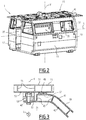
figure 2 est une vue en perspective de la cabine représentée sur lafigure 1 , les équipements de la cabine n'étant pas représentés, et l'élément de toiture étant rapporté sur la structure, et - la
figure 3 est une vue de détail, en coupe selon un plan vertical, de la jonction entre la structure de la cabine et l'élément de toiture représentés sur lesfigures 1 et2 .
- the
figure 1 is a perspective view, exploded in a vertical direction, of a cabin according to the invention, certain finishing elements of the cabin not being shown, - the
figure 2 is a perspective view of the cabin shown infigure 1 , the cabin equipment not being shown, and the roof element being attached to the structure, and - the
figure 3 is a detail view, in section along a vertical plane, of the junction between the cabin structure and the roof element shown in thefigures 1 and2 .
En référence aux
Le véhicule ferroviaire est avantageusement une locomotive, par exemple une locomotive de manœuvre dans laquelle la cabine 1 est par exemple située sensiblement au milieu du véhicule ferroviaire selon une direction longitudinale L de ce véhicule.The rail vehicle is advantageously a locomotive, for example a shunting locomotive in which the
La cabine 1 comprend une structure 5 mécano-soudée, avantageusement en un seul bloc, une pluralité d'équipements de cabine 10, et un élément de toiture 15.The
La structure 5 forme un plancher 17, et des parois latérales 19 de la cabine 1. La structure 5 définit un espace intérieur 21 de la cabine 1 destiné à recevoir les équipements de cabine 10.The
Les équipements de cabine 10 comprennent par exemple deux sièges 23, 25 (
Les sièges 23 et 25 font par exemple respectivement face aux pupitres 33 et 31 selon la direction longitudinale L.The
Les armoires électriques 27, 29 sont par exemple connectées électriquement aux pupitres 31, 33.The
Les parois latérales 19 définissent deux portes 35, 37 et des fenêtres 39 formant des ouvertures latérales. Toutefois, les parois latérales 19 sont dépourvues de toute ouverture latérale par laquelle il serait possible de faire passer les blocs formés par les équipements de cabine 10 vers l'espace intérieur 21.The
Les portes 35, 37 sont par exemple opposées l'une à l'autre longitudinalement. Les portes 35, 37 sont suffisamment larges pour permettre le passage d'un opérateur (non représenté), mais trop étroites pour permettre le passage d'au moins certains des équipements de cabine 10.The
Les fenêtres 39 sont toutes trop étroites pour permettre le passage d'au moins certains des équipements de cabine 10.The
Les parois latérales 19 définissent également ensemble une ouverture 40 dans la structure 5, l'ouverture étant opposée au plancher 17 selon une direction verticale V perpendiculaire à la direction longitudinale L.The
Comme visible sur la
L'ouverture 40 est par exemple rectangulaire ou carrée, et avantageusement sensiblement horizontale.The opening 40 is for example rectangular or square, and advantageously substantially horizontal.
L'ouverture 40 présente une extension longitudinale L1 et une extension transversale L2.The
L1 est par exemple supérieure à la longueur de l'équipement 10 le plus long.L1 is for example greater than the length of the
L2 est par exemple supérieure à la largeur de l'équipement 10 le plus large.L2 is for example greater than the width of the
Les parois latérales 19 définissent un bord 47 délimitant l'ouverture 40 et sur lequel l'élément de toiture 15 est fixé, par exemple par boulonnage.The
Le bord 47 est par exemple situé dans le prolongement de l'enveloppe interne 43.The
L'enveloppe externe 41 définit une surface de collage 49 sur laquelle l'élément de toiture 15 est collé et étanché.The
La surface de collage 49 et le bord 47 sont avantageusement horizontaux.The
L'élément de toiture 15 s'étend sensiblement dans un plan P, par exemple perpendiculaire à la direction verticale V. L'élément de toiture 15 ferme au moins partiellement, et, dans l'exemple représenté, totalement, l'ouverture 40. L'élément de toiture 15 est par exemple rectangulaire ou carré en vue selon la direction V.The
Par « fermer au moins partiellement », on entend ici que l'élément de toiture 15 s'étend en travers de l'ouverture 40 et est adapté pour former au minimum une structure du toit de la cabine 1.By “at least partially closing” is meant here that the
Comme visible sur la
L'enveloppe externe 51 et l'enveloppe interne 53 sont avantageusement reliées par des nervures 55.The
L'enveloppe interne 53 définit une surface de collage 57 collée sur la surface de collage 49 de la structure 5, avantageusement de manière étanche.The
Un procédé de fabrication de la cabine 1 va maintenant être décrit.A method of manufacturing the
Le procédé comprend la fabrication de la structure 5, la fixation des équipements de cabine 10 sur la structure, et la fixation de l'élément de toiture 15 sur la structure.The method includes fabricating the
La fabrication de la structure 5 comporte des sous-étapes connues en elles-mêmes et qui ne seront pas décrites ici. La particularité de cette étape de fabrication est qu'elle crée l'ouverture 40 présentant des dimensions perpendiculairement à la direction V qui sont suffisantes pour introduire dans l'espace intérieur 21 via l'ouverture 40 les équipements de cabine 10 dans l'espace intérieur 21 via l'ouverture 40, avant leur fixation sur le plancher 17 et/ou les parois latérales 19.The manufacture of
A nouveau, aucune des autres ouvertures de la structure 5 ne permettrait cette introduction.Again, none of the other openings in
Préalablement à leur introduction dans la structure 5, les équipements de cabine 10 sont assemblés de manière à former des blocs, et testés, de préférence en parallèle les uns avec les autres.Prior to their introduction into
Pour fixer l'élément de toiture 15 sur la structure 5, des boulons 59 (dont un seul est représenté sur la
Les boulons 59 sont avantageusement répartis le long du bord 47.The
Pour réaliser la fixation de l'élément de toiture 15, les surfaces de collage 49, 57 sont également collées l'une à l'autre, avantageusement de manière étanche.In order to fix the
La fixation de l'élément de toiture 15 par boulonnage et collage participe structurellement à la rigidité de la cabine 1.Fixing the
Grâce aux caractéristiques décrites ci-dessus, les équipements de cabine 10 sont apportés en bloc dans l'espace intérieur 21 via l'ouverture 40 et n'ont plus qu'à être fixés à la structure 5. Le procédé de fabrication est donc simplifié et est moins coûteux par rapport à des procédés antérieurs dans lesquels les équipements de cabine 10 étaient introduits en pièces détachées via les portes 17, 37 ou les fenêtres 39.Thanks to the characteristics described above, the
En outre, les équipements de cabine 10 sont avantageusement assemblés et testés, préalablement à leur installation dans l'espace intérieur 21, et de manière encore plus avantageuse en parallèle les uns avec les autres.In addition, the
L'assemblage de la structure 5 et de l'élément de toiture 15 est étanche grâce au collage, et participe avantageusement à la rigidité de la cabine 1.The assembly of the
Claims (7)
- Method for assembling a cab (1) for a railway vehicle, comprising the following steps:- manufacturing a mecano-welded structure (5), the structure (5) being adapted to form a floor (17) and side walls (19) of the cab (1), the structure (5) defining an interior space (21) which is to receive pieces of cab equipment (10), the side walls (19) together defining at least one opening (40) of the structure (5), the opening (40) being opposite the floor (17) in a direction (V) which is to be vertical,- fixing at least one of the pieces of cab equipment (10) to the structure (5), the fixed piece of cab equipment (10) being transported into the interior space (21) beforehand via the opening (40),characterised by the method step of- fixing a roof element (15) to the structure (5), the roof element (15) closing the opening (40) at least partially, fixing of the roof element (15) comprising bonding a first bonding surface (57) defined by the roof element (15) to a second bonding surface (49) defined by the structure (5).
- Method according to claim 1, wherein the fixed piece of cabin equipment (10) forms a unit, the side walls (19) having no lateral opening through which it would be possible to transport said unit to the interior space (21).
- Method according to claim 1 or 2, wherein the fixed piece of cabin equipment (10) comprises a console (31), an electrical cabinet (27) or a seat (23).
- Method according to any one of claims 1 to 3, comprising fixing multiple pieces of cab equipment (10) to the structure (5), each of the fixed pieces of cab equipment (10) being transported into the interior space (21) beforehand via the opening (40).
- Method according to claim 4, wherein said multiple fixed pieces of cab equipment (10) are assembled and tested beforehand, preferably in parallel with one another.
- Method according to any one of claims 1 to 5, wherein the roof element (15) is bolted to the structure (5).
- Cab (1) for a railway vehicle, the cab (1) being adapted to be manufactured by a method according to any one of claims 1 to 6 and comprising:- a mecano-welded structure (5), the structure (5) being adapted to form a floor (17) and side walls (19) of the cab (1), the structure (5) defining an interior space (21), the side walls (19) together defining at least one opening (40) of the structure (5), the opening (40) being opposite the floor (17) in a direction (V) which is to be vertical,- at least one piece of cab equipment (10) situated in the interior space (21) and fixed to the structure (5),- a roof element (15) attached to the structure and closing the opening (40) at least partially,characterised in that- bolts (59) fix the roof element (15) to the structure (5), the bolts (59) being distributed along an edge (47) of the structure (5) forming the opening (40), a first bonding surface (57) defined by the roof element (15) being bonded to a second bonding surface (49) defined by the structure (5).
Applications Claiming Priority (1)
| Application Number | Priority Date | Filing Date | Title |
|---|---|---|---|
| FR1857872A FR3085337B1 (en) | 2018-08-31 | 2018-08-31 | CABIN FOR RAILWAY VEHICLE AND ASSEMBLY PROCESS |
Publications (2)
| Publication Number | Publication Date |
|---|---|
| EP3617026A1 EP3617026A1 (en) | 2020-03-04 |
| EP3617026B1 true EP3617026B1 (en) | 2020-12-02 |
Family
ID=63896424
Family Applications (1)
| Application Number | Title | Priority Date | Filing Date |
|---|---|---|---|
| EP19194655.7A Active EP3617026B1 (en) | 2018-08-31 | 2019-08-30 | Cabin for a railway vehicle and assembly method |
Country Status (4)
| Country | Link |
|---|---|
| EP (1) | EP3617026B1 (en) |
| CN (1) | CN110871818B (en) |
| ES (1) | ES2855680T3 (en) |
| FR (1) | FR3085337B1 (en) |
Family Cites Families (7)
| Publication number | Priority date | Publication date | Assignee | Title |
|---|---|---|---|---|
| FR1129713A (en) * | 1955-08-05 | 1957-01-24 | Atel Const Nord De La France | New railway car |
| SE504608C2 (en) * | 1995-09-14 | 1997-03-17 | Scania Cv Ab | Vehicle cab and procedure for welding |
| FR2765543B1 (en) * | 1997-07-02 | 2005-01-07 | Alstom Ddf | RAILWAY VEHICLE COMPRISING AT LEAST ONE INTERCHANGEABLE END MODULE |
| JP3108052B2 (en) * | 1998-01-13 | 2000-11-13 | 川崎重工業株式会社 | Railway vehicle assembly method and railway vehicle |
| DE102009053750A1 (en) * | 2009-11-18 | 2011-05-19 | Man Nutzfahrzeuge Ag | Cab of a commercial vehicle with center roof module |
| US20150210330A1 (en) * | 2014-01-30 | 2015-07-30 | GM Global Technology Operations LLC | Motor compartment structure for a vehicle and method of attaching a motor compartment to a vehicle |
| CN104691563B (en) * | 2015-03-20 | 2017-05-24 | 南车株洲电力机车有限公司 | Locomotive cab and underframe thereof |
-
2018
- 2018-08-31 FR FR1857872A patent/FR3085337B1/en not_active Expired - Fee Related
-
2019
- 2019-08-29 CN CN201910809979.XA patent/CN110871818B/en active Active
- 2019-08-30 EP EP19194655.7A patent/EP3617026B1/en active Active
- 2019-08-30 ES ES19194655T patent/ES2855680T3/en active Active
Non-Patent Citations (1)
| Title |
|---|
| None * |
Also Published As
| Publication number | Publication date |
|---|---|
| CN110871818A (en) | 2020-03-10 |
| ES2855680T3 (en) | 2021-09-24 |
| FR3085337B1 (en) | 2021-01-15 |
| FR3085337A1 (en) | 2020-03-06 |
| EP3617026A1 (en) | 2020-03-04 |
| CN110871818B (en) | 2023-08-18 |
Similar Documents
| Publication | Publication Date | Title |
|---|---|---|
| EP1601074B1 (en) | Electrical cabinet with framework section pieces | |
| FR2911096A1 (en) | VEHICLE SEAT STRUCTURE AND SEAT COMPRISING SUCH A STRUCTURE | |
| EP3096999B1 (en) | Body shell structure of a motor vehicle with reinforcements for distributing forces linked to a rear shock absorber of the vehicle | |
| WO2012095576A1 (en) | Roof for a vehicle provided with longitudinal roof bars | |
| EP3617026B1 (en) | Cabin for a railway vehicle and assembly method | |
| EP1814773A1 (en) | Motor vehicle comprising a structure with a loading floor | |
| EP2443022A1 (en) | Assembly for an automobile including a floor, a side rail, a crossbeam, a mounting for a seat portion, and a box for closing the lower rail of a sliding door, and vehicle comprising such an assembly | |
| EP2172382B1 (en) | Bodyshell for railway vehicle and manufacturing process therefore | |
| EP2977287B1 (en) | Structural panel for a railway vehicle body and assembling method thereof | |
| EP3097000B1 (en) | Body structure of a motor vehicle with reinforcements for distributing the forces linked to a rear shock absorber of the vehicle | |
| EP0466588B1 (en) | Demountable isothermic cell for light delivery van | |
| EP2113447A1 (en) | Automobile structure, method for manufacturing same, and vehicle comprising such a structure. | |
| FR2717868A1 (en) | Components for assembling composite panels of isothermal box | |
| FR2800693A1 (en) | Motor vehicle body frame unit made in one piece with supports for ends of lengthwise members on either side of centre section | |
| FR3093063A1 (en) | Subassembly of bodywork elements of a motor vehicle, comprising two concurrent sheets between which is provided a reserve for receiving a sealing member | |
| EP3539806B1 (en) | Arrangement of an openable body section of a motor vehicle with lock reinforcement | |
| WO2012066208A2 (en) | Structural element of a vehicle strengthened by a reinforcing insert | |
| EP3163001B1 (en) | Door panel | |
| EP3969355B1 (en) | Sealing between a tunnel and a crossbeam constituting an underbody of a motor vehicle | |
| EP3254903B1 (en) | Part for attaching trim elements to a side structure element of a motor vehicle | |
| EP3737575B1 (en) | Central rail housing of a sliding door of a motor vehicle | |
| EP3672862B1 (en) | Set of body components for a motor vehicle secured together by an electric welding point by means of sockets | |
| EP3501954B1 (en) | Single-piece floor structure made of a composite material | |
| FR2934225A1 (en) | Lateral face for forming body structure of e.g. underground railway, has longitudinal wall including internal and external panels that are fixed with respect to one another along longitudinal edges and separated from one another by space | |
| FR3125789A1 (en) | Body part with multiple equipment assembly interfaces. |
Legal Events
| Date | Code | Title | Description |
|---|---|---|---|
| PUAI | Public reference made under article 153(3) epc to a published international application that has entered the european phase |
Free format text: ORIGINAL CODE: 0009012 |
|
| STAA | Information on the status of an ep patent application or granted ep patent |
Free format text: STATUS: THE APPLICATION HAS BEEN PUBLISHED |
|
| AK | Designated contracting states |
Kind code of ref document: A1 Designated state(s): AL AT BE BG CH CY CZ DE DK EE ES FI FR GB GR HR HU IE IS IT LI LT LU LV MC MK MT NL NO PL PT RO RS SE SI SK SM TR |
|
| AX | Request for extension of the european patent |
Extension state: BA ME |
|
| STAA | Information on the status of an ep patent application or granted ep patent |
Free format text: STATUS: REQUEST FOR EXAMINATION WAS MADE |
|
| 17P | Request for examination filed |
Effective date: 20200302 |
|
| RBV | Designated contracting states (corrected) |
Designated state(s): AL AT BE BG CH CY CZ DE DK EE ES FI FR GB GR HR HU IE IS IT LI LT LU LV MC MK MT NL NO PL PT RO RS SE SI SK SM TR |
|
| GRAP | Despatch of communication of intention to grant a patent |
Free format text: ORIGINAL CODE: EPIDOSNIGR1 |
|
| STAA | Information on the status of an ep patent application or granted ep patent |
Free format text: STATUS: GRANT OF PATENT IS INTENDED |
|
| RIC1 | Information provided on ipc code assigned before grant |
Ipc: B61D 17/04 20060101AFI20200623BHEP Ipc: B61D 17/06 20060101ALI20200623BHEP |
|
| INTG | Intention to grant announced |
Effective date: 20200713 |
|
| GRAS | Grant fee paid |
Free format text: ORIGINAL CODE: EPIDOSNIGR3 |
|
| GRAA | (expected) grant |
Free format text: ORIGINAL CODE: 0009210 |
|
| STAA | Information on the status of an ep patent application or granted ep patent |
Free format text: STATUS: THE PATENT HAS BEEN GRANTED |
|
| AK | Designated contracting states |
Kind code of ref document: B1 Designated state(s): AL AT BE BG CH CY CZ DE DK EE ES FI FR GB GR HR HU IE IS IT LI LT LU LV MC MK MT NL NO PL PT RO RS SE SI SK SM TR |
|
| REG | Reference to a national code |
Ref country code: GB Ref legal event code: FG4D Free format text: NOT ENGLISH |
|
| REG | Reference to a national code |
Ref country code: CH Ref legal event code: EP Ref country code: AT Ref legal event code: REF Ref document number: 1340612 Country of ref document: AT Kind code of ref document: T Effective date: 20201215 |
|
| REG | Reference to a national code |
Ref country code: IE Ref legal event code: FG4D Free format text: LANGUAGE OF EP DOCUMENT: FRENCH |
|
| REG | Reference to a national code |
Ref country code: DE Ref legal event code: R096 Ref document number: 602019001573 Country of ref document: DE |
|
| REG | Reference to a national code |
Ref country code: CH Ref legal event code: NV Representative=s name: NOVAGRAAF INTERNATIONAL SA, CH |
|
| REG | Reference to a national code |
Ref country code: DE Ref legal event code: R082 Ref document number: 602019001573 Country of ref document: DE Representative=s name: WR SERVICES GMBH, DE |
|
| PG25 | Lapsed in a contracting state [announced via postgrant information from national office to epo] |
Ref country code: RS Free format text: LAPSE BECAUSE OF FAILURE TO SUBMIT A TRANSLATION OF THE DESCRIPTION OR TO PAY THE FEE WITHIN THE PRESCRIBED TIME-LIMIT Effective date: 20201202 Ref country code: FI Free format text: LAPSE BECAUSE OF FAILURE TO SUBMIT A TRANSLATION OF THE DESCRIPTION OR TO PAY THE FEE WITHIN THE PRESCRIBED TIME-LIMIT Effective date: 20201202 Ref country code: GR Free format text: LAPSE BECAUSE OF FAILURE TO SUBMIT A TRANSLATION OF THE DESCRIPTION OR TO PAY THE FEE WITHIN THE PRESCRIBED TIME-LIMIT Effective date: 20210303 Ref country code: NO Free format text: LAPSE BECAUSE OF FAILURE TO SUBMIT A TRANSLATION OF THE DESCRIPTION OR TO PAY THE FEE WITHIN THE PRESCRIBED TIME-LIMIT Effective date: 20210302 |
|
| REG | Reference to a national code |
Ref country code: NL Ref legal event code: MP Effective date: 20201202 |
|
| REG | Reference to a national code |
Ref country code: AT Ref legal event code: MK05 Ref document number: 1340612 Country of ref document: AT Kind code of ref document: T Effective date: 20201202 |
|
| PG25 | Lapsed in a contracting state [announced via postgrant information from national office to epo] |
Ref country code: BG Free format text: LAPSE BECAUSE OF FAILURE TO SUBMIT A TRANSLATION OF THE DESCRIPTION OR TO PAY THE FEE WITHIN THE PRESCRIBED TIME-LIMIT Effective date: 20210302 Ref country code: LV Free format text: LAPSE BECAUSE OF FAILURE TO SUBMIT A TRANSLATION OF THE DESCRIPTION OR TO PAY THE FEE WITHIN THE PRESCRIBED TIME-LIMIT Effective date: 20201202 Ref country code: PL Free format text: LAPSE BECAUSE OF FAILURE TO SUBMIT A TRANSLATION OF THE DESCRIPTION OR TO PAY THE FEE WITHIN THE PRESCRIBED TIME-LIMIT Effective date: 20201202 Ref country code: SE Free format text: LAPSE BECAUSE OF FAILURE TO SUBMIT A TRANSLATION OF THE DESCRIPTION OR TO PAY THE FEE WITHIN THE PRESCRIBED TIME-LIMIT Effective date: 20201202 |
|
| PG25 | Lapsed in a contracting state [announced via postgrant information from national office to epo] |
Ref country code: HR Free format text: LAPSE BECAUSE OF FAILURE TO SUBMIT A TRANSLATION OF THE DESCRIPTION OR TO PAY THE FEE WITHIN THE PRESCRIBED TIME-LIMIT Effective date: 20201202 Ref country code: NL Free format text: LAPSE BECAUSE OF FAILURE TO SUBMIT A TRANSLATION OF THE DESCRIPTION OR TO PAY THE FEE WITHIN THE PRESCRIBED TIME-LIMIT Effective date: 20201202 |
|
| REG | Reference to a national code |
Ref country code: LT Ref legal event code: MG9D |
|
| PG25 | Lapsed in a contracting state [announced via postgrant information from national office to epo] |
Ref country code: EE Free format text: LAPSE BECAUSE OF FAILURE TO SUBMIT A TRANSLATION OF THE DESCRIPTION OR TO PAY THE FEE WITHIN THE PRESCRIBED TIME-LIMIT Effective date: 20201202 Ref country code: SM Free format text: LAPSE BECAUSE OF FAILURE TO SUBMIT A TRANSLATION OF THE DESCRIPTION OR TO PAY THE FEE WITHIN THE PRESCRIBED TIME-LIMIT Effective date: 20201202 Ref country code: SK Free format text: LAPSE BECAUSE OF FAILURE TO SUBMIT A TRANSLATION OF THE DESCRIPTION OR TO PAY THE FEE WITHIN THE PRESCRIBED TIME-LIMIT Effective date: 20201202 Ref country code: LT Free format text: LAPSE BECAUSE OF FAILURE TO SUBMIT A TRANSLATION OF THE DESCRIPTION OR TO PAY THE FEE WITHIN THE PRESCRIBED TIME-LIMIT Effective date: 20201202 Ref country code: PT Free format text: LAPSE BECAUSE OF FAILURE TO SUBMIT A TRANSLATION OF THE DESCRIPTION OR TO PAY THE FEE WITHIN THE PRESCRIBED TIME-LIMIT Effective date: 20210405 Ref country code: RO Free format text: LAPSE BECAUSE OF FAILURE TO SUBMIT A TRANSLATION OF THE DESCRIPTION OR TO PAY THE FEE WITHIN THE PRESCRIBED TIME-LIMIT Effective date: 20201202 |
|
| PG25 | Lapsed in a contracting state [announced via postgrant information from national office to epo] |
Ref country code: AT Free format text: LAPSE BECAUSE OF FAILURE TO SUBMIT A TRANSLATION OF THE DESCRIPTION OR TO PAY THE FEE WITHIN THE PRESCRIBED TIME-LIMIT Effective date: 20201202 |
|
| REG | Reference to a national code |
Ref country code: DE Ref legal event code: R097 Ref document number: 602019001573 Country of ref document: DE |
|
| PG25 | Lapsed in a contracting state [announced via postgrant information from national office to epo] |
Ref country code: IS Free format text: LAPSE BECAUSE OF FAILURE TO SUBMIT A TRANSLATION OF THE DESCRIPTION OR TO PAY THE FEE WITHIN THE PRESCRIBED TIME-LIMIT Effective date: 20210402 |
|
| PLBE | No opposition filed within time limit |
Free format text: ORIGINAL CODE: 0009261 |
|
| STAA | Information on the status of an ep patent application or granted ep patent |
Free format text: STATUS: NO OPPOSITION FILED WITHIN TIME LIMIT |
|
| PG25 | Lapsed in a contracting state [announced via postgrant information from national office to epo] |
Ref country code: IT Free format text: LAPSE BECAUSE OF FAILURE TO SUBMIT A TRANSLATION OF THE DESCRIPTION OR TO PAY THE FEE WITHIN THE PRESCRIBED TIME-LIMIT Effective date: 20201202 Ref country code: AL Free format text: LAPSE BECAUSE OF FAILURE TO SUBMIT A TRANSLATION OF THE DESCRIPTION OR TO PAY THE FEE WITHIN THE PRESCRIBED TIME-LIMIT Effective date: 20201202 |
|
| 26N | No opposition filed |
Effective date: 20210903 |
|
| PG25 | Lapsed in a contracting state [announced via postgrant information from national office to epo] |
Ref country code: SI Free format text: LAPSE BECAUSE OF FAILURE TO SUBMIT A TRANSLATION OF THE DESCRIPTION OR TO PAY THE FEE WITHIN THE PRESCRIBED TIME-LIMIT Effective date: 20201202 Ref country code: DK Free format text: LAPSE BECAUSE OF FAILURE TO SUBMIT A TRANSLATION OF THE DESCRIPTION OR TO PAY THE FEE WITHIN THE PRESCRIBED TIME-LIMIT Effective date: 20201202 |
|
| PG25 | Lapsed in a contracting state [announced via postgrant information from national office to epo] |
Ref country code: MC Free format text: LAPSE BECAUSE OF FAILURE TO SUBMIT A TRANSLATION OF THE DESCRIPTION OR TO PAY THE FEE WITHIN THE PRESCRIBED TIME-LIMIT Effective date: 20201202 |
|
| REG | Reference to a national code |
Ref country code: BE Ref legal event code: MM Effective date: 20210831 |
|
| PG25 | Lapsed in a contracting state [announced via postgrant information from national office to epo] |
Ref country code: IS Free format text: LAPSE BECAUSE OF FAILURE TO SUBMIT A TRANSLATION OF THE DESCRIPTION OR TO PAY THE FEE WITHIN THE PRESCRIBED TIME-LIMIT Effective date: 20210402 Ref country code: LU Free format text: LAPSE BECAUSE OF NON-PAYMENT OF DUE FEES Effective date: 20210830 |
|
| PG25 | Lapsed in a contracting state [announced via postgrant information from national office to epo] |
Ref country code: IE Free format text: LAPSE BECAUSE OF NON-PAYMENT OF DUE FEES Effective date: 20210830 Ref country code: BE Free format text: LAPSE BECAUSE OF NON-PAYMENT OF DUE FEES Effective date: 20210831 |
|
| PG25 | Lapsed in a contracting state [announced via postgrant information from national office to epo] |
Ref country code: CY Free format text: LAPSE BECAUSE OF FAILURE TO SUBMIT A TRANSLATION OF THE DESCRIPTION OR TO PAY THE FEE WITHIN THE PRESCRIBED TIME-LIMIT Effective date: 20201202 |
|
| PG25 | Lapsed in a contracting state [announced via postgrant information from national office to epo] |
Ref country code: HU Free format text: LAPSE BECAUSE OF FAILURE TO SUBMIT A TRANSLATION OF THE DESCRIPTION OR TO PAY THE FEE WITHIN THE PRESCRIBED TIME-LIMIT; INVALID AB INITIO Effective date: 20190830 |
|
| P01 | Opt-out of the competence of the unified patent court (upc) registered |
Effective date: 20230823 |
|
| PGFP | Annual fee paid to national office [announced via postgrant information from national office to epo] |
Ref country code: CZ Payment date: 20230821 Year of fee payment: 5 Ref country code: CH Payment date: 20230902 Year of fee payment: 5 |
|
| PGFP | Annual fee paid to national office [announced via postgrant information from national office to epo] |
Ref country code: FR Payment date: 20230828 Year of fee payment: 5 Ref country code: DE Payment date: 20230821 Year of fee payment: 5 |
|
| PGFP | Annual fee paid to national office [announced via postgrant information from national office to epo] |
Ref country code: ES Payment date: 20231027 Year of fee payment: 5 |
|
| GBPC | Gb: european patent ceased through non-payment of renewal fee |
Effective date: 20230830 |
|
| PG25 | Lapsed in a contracting state [announced via postgrant information from national office to epo] |
Ref country code: MK Free format text: LAPSE BECAUSE OF FAILURE TO SUBMIT A TRANSLATION OF THE DESCRIPTION OR TO PAY THE FEE WITHIN THE PRESCRIBED TIME-LIMIT Effective date: 20201202 |