EP3612460B1 - Verschluss mit deckelkappe - Google Patents
Verschluss mit deckelkappe Download PDFInfo
- Publication number
- EP3612460B1 EP3612460B1 EP18719472.5A EP18719472A EP3612460B1 EP 3612460 B1 EP3612460 B1 EP 3612460B1 EP 18719472 A EP18719472 A EP 18719472A EP 3612460 B1 EP3612460 B1 EP 3612460B1
- Authority
- EP
- European Patent Office
- Prior art keywords
- closure
- lid cap
- pressing
- cap
- lid
- Prior art date
- Legal status (The legal status is an assumption and is not a legal conclusion. Google has not performed a legal analysis and makes no representation as to the accuracy of the status listed.)
- Active
Links
Images


Classifications
-
- B—PERFORMING OPERATIONS; TRANSPORTING
- B65—CONVEYING; PACKING; STORING; HANDLING THIN OR FILAMENTARY MATERIAL
- B65D—CONTAINERS FOR STORAGE OR TRANSPORT OF ARTICLES OR MATERIALS, e.g. BAGS, BARRELS, BOTTLES, BOXES, CANS, CARTONS, CRATES, DRUMS, JARS, TANKS, HOPPERS, FORWARDING CONTAINERS; ACCESSORIES, CLOSURES, OR FITTINGS THEREFOR; PACKAGING ELEMENTS; PACKAGES
- B65D47/00—Closures with filling and discharging, or with discharging, devices
- B65D47/04—Closures with discharging devices other than pumps
- B65D47/06—Closures with discharging devices other than pumps with pouring spouts or tubes; with discharge nozzles or passages
- B65D47/08—Closures with discharging devices other than pumps with pouring spouts or tubes; with discharge nozzles or passages having articulated or hinged closures
-
- B—PERFORMING OPERATIONS; TRANSPORTING
- B65—CONVEYING; PACKING; STORING; HANDLING THIN OR FILAMENTARY MATERIAL
- B65D—CONTAINERS FOR STORAGE OR TRANSPORT OF ARTICLES OR MATERIALS, e.g. BAGS, BARRELS, BOTTLES, BOXES, CANS, CARTONS, CRATES, DRUMS, JARS, TANKS, HOPPERS, FORWARDING CONTAINERS; ACCESSORIES, CLOSURES, OR FITTINGS THEREFOR; PACKAGING ELEMENTS; PACKAGES
- B65D47/00—Closures with filling and discharging, or with discharging, devices
- B65D47/04—Closures with discharging devices other than pumps
- B65D47/06—Closures with discharging devices other than pumps with pouring spouts or tubes; with discharge nozzles or passages
- B65D47/08—Closures with discharging devices other than pumps with pouring spouts or tubes; with discharge nozzles or passages having articulated or hinged closures
- B65D47/0804—Closures with discharging devices other than pumps with pouring spouts or tubes; with discharge nozzles or passages having articulated or hinged closures integrally formed with the base element provided with the spout or discharge passage
- B65D47/0833—Hinges without elastic bias
- B65D47/0838—Hinges without elastic bias located at an edge of the base element
-
- B—PERFORMING OPERATIONS; TRANSPORTING
- B65—CONVEYING; PACKING; STORING; HANDLING THIN OR FILAMENTARY MATERIAL
- B65D—CONTAINERS FOR STORAGE OR TRANSPORT OF ARTICLES OR MATERIALS, e.g. BAGS, BARRELS, BOTTLES, BOXES, CANS, CARTONS, CRATES, DRUMS, JARS, TANKS, HOPPERS, FORWARDING CONTAINERS; ACCESSORIES, CLOSURES, OR FITTINGS THEREFOR; PACKAGING ELEMENTS; PACKAGES
- B65D50/00—Closures with means for discouraging unauthorised opening or removal thereof, with or without indicating means, e.g. child-proof closures
- B65D50/02—Closures with means for discouraging unauthorised opening or removal thereof, with or without indicating means, e.g. child-proof closures openable or removable by the combination of plural actions
- B65D50/04—Closures with means for discouraging unauthorised opening or removal thereof, with or without indicating means, e.g. child-proof closures openable or removable by the combination of plural actions requiring the combination of simultaneous actions, e.g. depressing and turning, lifting and turning, maintaining a part and turning another one
-
- B—PERFORMING OPERATIONS; TRANSPORTING
- B65—CONVEYING; PACKING; STORING; HANDLING THIN OR FILAMENTARY MATERIAL
- B65D—CONTAINERS FOR STORAGE OR TRANSPORT OF ARTICLES OR MATERIALS, e.g. BAGS, BARRELS, BOTTLES, BOXES, CANS, CARTONS, CRATES, DRUMS, JARS, TANKS, HOPPERS, FORWARDING CONTAINERS; ACCESSORIES, CLOSURES, OR FITTINGS THEREFOR; PACKAGING ELEMENTS; PACKAGES
- B65D50/00—Closures with means for discouraging unauthorised opening or removal thereof, with or without indicating means, e.g. child-proof closures
- B65D50/02—Closures with means for discouraging unauthorised opening or removal thereof, with or without indicating means, e.g. child-proof closures openable or removable by the combination of plural actions
- B65D50/04—Closures with means for discouraging unauthorised opening or removal thereof, with or without indicating means, e.g. child-proof closures openable or removable by the combination of plural actions requiring the combination of simultaneous actions, e.g. depressing and turning, lifting and turning, maintaining a part and turning another one
- B65D50/045—Closures with means for discouraging unauthorised opening or removal thereof, with or without indicating means, e.g. child-proof closures openable or removable by the combination of plural actions requiring the combination of simultaneous actions, e.g. depressing and turning, lifting and turning, maintaining a part and turning another one where one action elastically deforms or deflects at least part of the closure, the container or an intermediate element, e.g. a ring
- B65D50/046—Closures with means for discouraging unauthorised opening or removal thereof, with or without indicating means, e.g. child-proof closures openable or removable by the combination of plural actions requiring the combination of simultaneous actions, e.g. depressing and turning, lifting and turning, maintaining a part and turning another one where one action elastically deforms or deflects at least part of the closure, the container or an intermediate element, e.g. a ring and such deformation causes the disengagement of locking means, e.g. the release of a pawl-like element from a tooth or abutment, to allow removal of the closure by simultaneous rotation
-
- B—PERFORMING OPERATIONS; TRANSPORTING
- B65—CONVEYING; PACKING; STORING; HANDLING THIN OR FILAMENTARY MATERIAL
- B65D—CONTAINERS FOR STORAGE OR TRANSPORT OF ARTICLES OR MATERIALS, e.g. BAGS, BARRELS, BOTTLES, BOXES, CANS, CARTONS, CRATES, DRUMS, JARS, TANKS, HOPPERS, FORWARDING CONTAINERS; ACCESSORIES, CLOSURES, OR FITTINGS THEREFOR; PACKAGING ELEMENTS; PACKAGES
- B65D51/00—Closures not otherwise provided for
- B65D51/18—Arrangements of closures with protective outer cap-like covers or of two or more co-operating closures
-
- B—PERFORMING OPERATIONS; TRANSPORTING
- B65—CONVEYING; PACKING; STORING; HANDLING THIN OR FILAMENTARY MATERIAL
- B65D—CONTAINERS FOR STORAGE OR TRANSPORT OF ARTICLES OR MATERIALS, e.g. BAGS, BARRELS, BOTTLES, BOXES, CANS, CARTONS, CRATES, DRUMS, JARS, TANKS, HOPPERS, FORWARDING CONTAINERS; ACCESSORIES, CLOSURES, OR FITTINGS THEREFOR; PACKAGING ELEMENTS; PACKAGES
- B65D2251/00—Details relating to container closures
- B65D2251/0003—Two or more closures
- B65D2251/0006—Upper closure
- B65D2251/0028—Upper closure of the 51-type
-
- B—PERFORMING OPERATIONS; TRANSPORTING
- B65—CONVEYING; PACKING; STORING; HANDLING THIN OR FILAMENTARY MATERIAL
- B65D—CONTAINERS FOR STORAGE OR TRANSPORT OF ARTICLES OR MATERIALS, e.g. BAGS, BARRELS, BOTTLES, BOXES, CANS, CARTONS, CRATES, DRUMS, JARS, TANKS, HOPPERS, FORWARDING CONTAINERS; ACCESSORIES, CLOSURES, OR FITTINGS THEREFOR; PACKAGING ELEMENTS; PACKAGES
- B65D2251/00—Details relating to container closures
- B65D2251/0003—Two or more closures
- B65D2251/0068—Lower closure
- B65D2251/0087—Lower closure of the 47-type
-
- B—PERFORMING OPERATIONS; TRANSPORTING
- B65—CONVEYING; PACKING; STORING; HANDLING THIN OR FILAMENTARY MATERIAL
- B65D—CONTAINERS FOR STORAGE OR TRANSPORT OF ARTICLES OR MATERIALS, e.g. BAGS, BARRELS, BOTTLES, BOXES, CANS, CARTONS, CRATES, DRUMS, JARS, TANKS, HOPPERS, FORWARDING CONTAINERS; ACCESSORIES, CLOSURES, OR FITTINGS THEREFOR; PACKAGING ELEMENTS; PACKAGES
- B65D2251/00—Details relating to container closures
- B65D2251/10—Details of hinged closures
- B65D2251/1016—Means for locking the closure in closed position
- B65D2251/105—The closure having a part fitting over the rim of the container or spout and retained by snapping over integral beads or projections
Definitions
- the invention relates to a closure with a cover cap.
- Such closures are screwed onto the nozzle of canisters, for example on oil canisters, canisters or plastic bottles for liquid detergents and many other liquids or free-flowing goods.
- the closure screwed onto the nozzle then forms a pouring spout and after swiveling open the associated cover cap, a uniform jet of liquid or pouring material can be poured out or poured out in a controlled manner.
- the cover caps on such closures are held on the closure via a hinge.
- the hinges can be designed in such a way that they hold the pivoted-open cover flap in the open position.
- the lid cap When the lid cap is swiveled down, it must be swiveled over a maximum tension of the hinge, after which the lid cap swings down and the last few degrees of angle for pivoting the lid into the closed position are overcome by applying pressure from above on the lid flap.
- the lid cap assumes the function that nothing falls through the closure into the container when the canister or container is not in use, and on the other hand that no contents are accidentally spilled, i.e. the closure is tightly closed.
- Such closures are found in many Millions of copies on corresponding canisters and containers.
- lid caps are held on the closure with relatively weak claws, or in the other extreme they are clawed too tightly with it, so that the opening of the cover cap is difficult, at least for people with limited strength in their hands.
- Another disadvantage of many known lid caps is that they can also be easily swung open by small children, which would be better prevented in order to prevent small children from drinking from such bottles or spilling their contents.
- the object of this invention is therefore to create a closure with a cover cap in which, when the cover cap is pivoted onto the closure, it easily snaps into place on the closure and is then securely held on the closure in the closed position so that it can also be tipped over or dropped equipped container does not jump up on the ground, and which cannot be opened with one hand only by a pivoting movement with sufficient force.
- a closure with a cover cap which is integrally formed pivotably on the closure by means of a hinge, and which, when pivoted closed, detachably claws with the closure at least two points or snaps into it, characterized in that the cover cap by pressing on only one The only point is deformable in such a way that the claws can be released by this deformation and the cover cap with sustained pressure can be swung open with one hand beyond the clawing means.
- Latching or clawing means act between the closure and the cover cap, so that when the cover cap is pivoted onto the closure, these two or more parts snap or claw into one another.
- the latching or clawing means can be implemented, for example, by barbs that hook onto one another.
- barbs which are molded on their inner walls, slide over barbs or in recesses that are present on the outside of the closure, in that the walls of the cover cap move elastically to the outside, and the barbs then snap into the recesses or they claw on each other and form a deep claw.
- barbs shaped elements that fit into one another can be molded on.
- the Figure 1 shows an example of an embodiment of the closure according to the invention with a closed cover cap in a perspective view obliquely from above.
- the lock 1 At the bottom there is the lock 1, and at the top the lid cap 2 is pivoted onto it.
- the hinge 3 On the back there is the hinge 3, in a known manner.
- the cover cap 2 forms a protruding pushbutton 4 on its front side, which, together with the associated front side wall of the pushbutton 4, can be pushed a bit in the direction of the hinge 3.
- the Figure 2 shows this closure with closed cover cap 2 seen obliquely from below.
- a sleeve 5 formed inside the closure 1 with its internal thread 6 can be seen.
- the closure can thus be screwed onto the threaded connector of a container or a bottle.
- the sleeve 5 is closed by a disk 8, with the exception of a central hole which serves as a pouring or pouring hole 7.
- the hinge 3 which integrally connects the two parts 1, 2, and the associated two tensioning straps 25, according to a known type.
- the Figure 3 shows the closure 1 with the lid cap 2 slightly pivoted open, with the locking of the barbs released.
- a step 9 is formed on each of its two sides, onto which the cover cap 2 can be pivoted with its circumferential side wall 10 so that the lower edge 11 of the side wall 10 rests snugly on this step 9.
- a recess 12 with a sharp corner 13 is formed above the step 9.
- Barbs that are not visible here on the inside of the side walls 10 can snap into these depressions 12 on both sides of the pouring cap 1 because the side walls 10 can elastically yield to the outside or give way when the barbs with their inclined surfaces over the upper outer edge 14 of the lock 1 slip.
- At the front of the closure 1 there is a recess 16 set back from the other outer side 15.
- this forms an unlocking and pressing point 17, here in the form of an oval push button 4, the lower half of which fits into the recess 16 as a free disk , while the upper half of the push button 4 is connected to the side wall 10 of the cover cap 2 in a stiffened manner.
- the step 9 in the front area 18 of the closure 1 is widened.
- the side wall of the lid cap can be pushed inwards on this step 9, which is widened at the front, by pressing the push button 4
- the two side walls 10 of the cover cap 2 bulge out laterally and the barbs formed on their inner sides are removed from the depressions 12 on Lock 1 is extended and the locking is released.
- the cover cap 2 can be pivoted open about the hinge 3.
- the Figure 4 gives a glimpse into the closure 1 with the cover cap 2 slightly pivoted open, with the barbs released, seen from obliquely below.
- a reinforcing rib 21 supports the stability of the connecting piece 19 in the interior of the cover cap 2.
- FIG Figure 6 shows the closure 1 with the lid cap 2 pivoted open by 180 °, seen obliquely from below, and FIG Figure 7 shows it from above in a floor plan.
- the connector 19 with the seal 20 fits into the interior of the recess 24.
- the circumferential wall 22 of the recess 24 can also carry a seal.
- On both sides of the hinge 3 one can see a tensioning strap 25 in this illustration. These tensioning straps 25 ensure that the cover cap 2 closes and closes with a slight deformation of the entire closure 1 and its cover cap 2 over a maximum tension can be swung open again. This ensures that the cover cap 2 remains in its open position.
- the Figure 8 shows the closure 1 with the lid cap 2 slightly pivoted open, shown in a central longitudinal section.
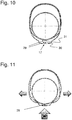
- the centering means can consist of a rib 30 behind the push button which, when pressed, is pressed into a centering groove 31 of V-shaped cross-section on the closure and thus centers the unlocking and pressing point 17 so that the side walls 10 of the cover cap 2 bulge out symmetrically towards the outside, as with the two small arrows in Figure 11 and both barbs 26 are moved evenly out of the depressions 12 on their insides.
- the closure takes place simply by closing the cover cap 2 with sufficient pressure on its upper side.
- the barbs slide with their inclined surfaces 28 on the outer edge of the circumferential step past the closure 1 and snap into the recesses 12 below, the sharp edge 27 of each barb 26 engaging with the sharp corner 13 of the associated recess 12 on the closure.
- the closure is always opened with a double action but possible with one hand, namely on the one hand by pressing a single unlocking and pressing point 17, that is, on a single push button 4, and at the same time swiveling the cover cap 2. This can be done with the help of both hands, but it is also possible with one hand. This is a problem for small children. And, moreover, this lid cap 2 remains securely held on the closure 1 even if a container falls over or falls, for example from a table onto a floor. This means that the closure remains tight even in these cases.
Landscapes
- Engineering & Computer Science (AREA)
- Mechanical Engineering (AREA)
- Closures For Containers (AREA)
Description
- Die Erfindung betrifft einen Verschluss mit Deckelkappe. Solche Verschlüsse werden auf die Stutzen von Kanistern aufgeschraubt, etwa auf Ölkanister, Kanister oder Kunststoff-Flaschen für flüssige Waschmittel und viele andere Flüssigkeiten oder rieselfähige Güter. Der auf den Stutzen aufgeschraubte Verschluss bildet dann einen Ausguss-Schnabel und nach Aufschwenken der zugehörigen Deckelkappe kann ein gleichmässiger Strahl Flüssigkeit oder Rieselgut kontrolliert ausgegossen bzw. ausgeschüttet werden. Die Deckelkappen an solchen Verschlüssen sind bei Kunststoff-Verschlüssen über ein Scharnier am Verschluss gehalten. Die Scharniere können so gestaltet sein, dass sie die aufgeschwenkte Deckelklappe in der Offenstellung halten. Beim Niederschwenken der Deckelkappe muss diese über ein Spannungsmaximum des Scharniers geschwenkt werden, wonach die Deckelkappe niederschwenkt und die letzten paar Winkelgrade für das Zuschwenken in die Schliess-Stellung durch Druck von oben auf die Deckelklappe überwunden werden. Dabei sind Widerhaken, Rippen oder Rillen auf der Innenseite der Deckelkappe vorhanden, die mit Widerhaken, Rippen oder Rillen am Verschluss zusammenwirken, sodass die Deckelkappe in ihrer Schliessstellung am Verschluss einrastet und ihn darauf festhält.
- Die Deckelkappe übernimmt die Funktion, dass bei Nichtgebrauch des Kanisters oder Behälters nichts durch den Verschluss in den Behälter fällt, und andererseits dass kein Inhalt unbeabsichtigt verschüttet wird, das heisst der Verschluss dichtend verschlossen ist. Solche Verschlüsse befinden sich in vielen Millionen Exemplaren auf entsprechenden Kanistern und Behältern.
- Herkömmliche Verschlüsse und ihre zugehörigen Deckelkappen, wie der im Dokument
US4310105 offenbarte Verschluss, weisen den Nachteil auf, dass bei einem Umstürzen der Behälter oder Flaschen die Deckelkappen oftmals aufspringen, weil der von ihnen erlittene Schlag beim Auftreffen auf dem Boden zum Lösen der knapp bemessenen Verkrallung mit dem Verschluss führt. Die Widerhaken, Rippen oder Rillen sind so gestaltet, dass sie beim Zuschwenken der Deckelkappe leicht nachgeben und damit einander passieren können, wonach sie dann aneinander einhaken. Zum Lösen wird die Verkrallung durch erhöhte Zugkraft für das Aufschwenken der Deckelkappe überwunden. Viele solche Deckelkappen sind mit relativ schwacher Verkrallung auf dem Verschluss gehalten, oder im anderen Extrem sind sie zu stark mit ihm verkrallt, sodass das Aufschwenken der Deckelkappe Mühe bereitet, zumindest für Personen mit begrenzter Kraft in den Händen. Ein weiterer Nachteil vieler bekannter Deckelkappen ist auch darin zu sehen, dass sie auch von Kleinkindern ohne Weiteres aufschwenkbar sind, was besser verhindert würde, um zu vermeiden, dass Kleinkinder aus solchen Flaschen trinken oder ihren Inhalt verschütten können. - Die Aufgabe dieser Erfindung ist es deshalb, einen Verschluss mit Deckelkappe zu schaffen, bei dem beim Zuschwenken der Deckelkappe auf den Verschluss dieselbe mühelos am Verschluss einrastet und dann auf dem Verschluss in Schliesslage sicher gehalten ist, sodass sie auch bei einem Umfallen oder Herabstürzen des damit ausgerüsteten Behälters auf den Boden nicht aufspringt, und die nicht einzig durch eine Schwenkbewegung mit hinreichender Kraft einhändig öffenbar ist.
- Diese Aufgabe wird gelöst von einem Verschluss mit Deckelkappe, die mittels eines Scharniers auf dem Verschluss schwenkbar angeformt ist, und die beim Zuschwenken lösbar mit dem Verschluss an mindestens zwei Stellen verkrallt oder an ihm einrastet, dadurch gekennzeichnet, dass die Deckelkappe durch Druck auf nur eine einzige Stelle so deformierbar ist, dass die Verkrallungen durch diese Deformation lösbar sind und die Deckelkappe bei anhaltendem Druck über die Verkrallungsmittel hinaus einhändig aufschwenkbar ist.
- In den Figuren wird eine beispielsweise Ausführung eines solchen Verschlusses mit Deckelkappe dargestellt und sie wird im Folgenden beschrieben und ihre Funktion wird erklärt.
- Es zeigt
- Figur 1:
- Den Verschluss mit geschlossener Deckelkappe;
- Figur 2:
- Den Verschluss mit geschlossener Deckelkappe von schräg unten gesehen;
- Figur 3:
- Den Verschluss mit leicht aufgeschwenkter Deckelkappe, mit gelöster Verrastung der Widerhaken;
- Figur 4:
- Den Verschluss mit leicht aufgeschwenkter Deckelkappe, mit gelöster Verrastung der Widerhaken, von schräg unten gesehen;
- Figur 5:
- Den Verschluss mit um 180° aufgeschwenkter Deckelkappe;
- Figur 6:
- Den Verschluss mit um 180° aufgeschwenkter Deckelkappe von schräg unten gesehen;
- Figur 7:
- Den Verschluss mit um 180° aufgeschwenkter Deckelkappe in einem Grundriss dargestellt;
- Figur 8:
- Den Verschluss mit leicht aufgeschwenkter Deckelkappe in einem mittigen Längsschnitt dargestellt;
- Figur 9:
- Eine schematische Darstellung von Deckel und Verschluss in einem Horizontalschnitt in einer Draufsicht;
- Figur 10:
- Eine schematische Darstellung von Deckel und Verschluss in einem Horizontalschnitt in einer Draufsicht, mit einer Zentriereinrichtung;
- Figur 11:
- Die schematische Darstellung von Deckel und Verschluss nach
Figur 10 mit geschlossener Zentriereinrichtung. - Zwischen dem Verschluss und der Deckelkappe wirken Verrastungs- oder Verkrallungsmittel, sodass beim Zuschwenken der Deckelkappe auf den Verschluss diese beiden oder mehreren Teile aneinander einrasten oder verkrallen. Die Verrastungs- oder Verkrallungsmittel können zum Beispiel durch Widerhaken realisiert sein, die aneinander einhaken. Beim Zuschwenken der Deckelkappe gleiten Widerhaken, die an ihren Innenwänden angeformt sind, über Widerhaken oder in Ausnehmungen, die aussen am Verschluss vorhanden sind, indem die Wände der Deckelkappe elastisch nach aussen ausweichen, und die Widerhaken rasten hernach in den Ausnehmungen ein oder sie verkrallen sich aneinander und bilden eine satte Verkrallung. Anstelle von Widerhaken können ineinander passende Formelemente angeformt sein. Herkömmliche Verschlüsse mit Deckelkappen erlauben bloss ein schwaches Einklicken der Deckelkappe am Verschluss zu deren Festhaltung in der Schliess-Stellung, sodass mit nur wenig Kraft diese Festhaltung überwindbar ist und die Deckelkappe aufschwenkbar ist. Will man eine stärkere Verkrallung realisieren, so stellt sich die Frage, wie dieselbe zum Öffnen der Deckelkappe wieder gelöst werden kann.
- Die
Figur 1 zeigt eine beispielsweise Ausführung des erfindungsgemässen Verschlusses mit geschlossener Deckelkappe in einer perspektivischen Ansicht von schräg oben. Unten befindet sich der Verschluss 1, und oben daraufgeschwenkt die Deckelkappe 2. Auf der Rückseite befindet sich das Scharnier 3, in bekannter Manier. Als Besonderheit bildet die Deckelkappe 2 auf ihrer Frontseite einen vorstehenden Druckknopf 4, welcher elastisch mitsamt der zugehörigen Frontseitenwand des Druckknopfes 4 ein stückweit in Richtung zum Scharnier 3 hin drückbar ist. - Die
Figur 2 zeigt diesen Verschluss mit geschlossener Deckelkappe 2 von schräg unten gesehen. In dieser Ansicht erkennt man eine im Innern des Verschlusses 1 ausgeformte Muffe 5 mit ihrem Innengewinde 6. Damit kann der Verschluss auf den Gewindestutzen eines Behälters oder einer Flasche aufgeschraubt werden. Oben ist die Muffe 5 von einer Scheibe 8 verschlossen, bis auf ein zentrales Loch, das als Ausgiess- oder Ausschüttloch 7 dient. Am hinteren Ende des Verschlusses 1 und seiner Deckelkappe 2 sieht man das Scharnier 3, welches die beiden Teile 1, 2 einstückig verbindet, und die zugehörigen zwei Spannbänder 25, nach bekannter Art. - Die
Figur 3 zeigt den Verschluss 1 mit leicht aufgeschwenkter Deckelkappe 2, mit gelöster Verrastung der Widerhaken. Am Verschluss 1 ist an seinen beiden Seiten je eine Stufe 9 gebildet, auf welche die Deckelkappe 2 mit ihrer umlaufenden Seitenwand 10 passgenau abschwenkbar ist, sodass also der untere Rand 11 der Seitenwand 10 auf dieser Stufe 9 satt aufliegt. Oberhalb der Stufe 9 ist eine Vertiefung 12 mit oben scharfer Ecke 13 ausgebildet. Hier nicht sichtbare Widerhaken auf der Innenseite der Seitenwände 10 können in diese Vertiefungen 12 auf beiden Seiten des Ausgiess-Verschlusses 1 einrasten, weil die Seitenwände 10 gegen aussen elastisch ausweichen können bzw. nachgeben können, wenn die Widerhaken mit ihren Schrägflächen über den oberen äusseren Rand 14 des Verschlusses 1 rutschen. Vorne am Verschluss 1 befindet sich eine gegenüber der sonstigen Aussenseite 15 zurückversetzte Vertiefung 16. Vorne an der Deckelkappe 2 formt diese eine Entriegelungs- und Eindrückstelle 17, hier in Form eines ovalen Druckknopfes 4 aus, dessen untere Hälfte als freie Scheibe in die Vertiefung 16 einpasst, während die obere Hälfte des Druckknopfes 4 mit der Seitenwand 10 der Deckelkappe 2 versteift mit dieser verbunden ist. Wie man in dieserFigur 3 erkennt, ist die Stufe 9 im vorderen Bereich 18 des Verschlusses 1 verbreitert. Wenn nun der untere Rand 11 der Seitenwand 10 der Deckelkappe 2 auf der Stufe 9 satt und bündig mit der Aussenwand des Verschlusses 1 aufliegt, so lässt sich die Seitenwand der Deckelkappe auf dieser vorne verbreiterten Stufe 9 nach innen schieben, durch Druck auf den Druckknopf 4. In der Folge buchten die beiden Seitenwände 10 der Deckelkappe 2 seitlich aus und die an ihren Innenseiten angeformten Widerhaken werden aus den Vertiefungen 12 am Verschluss 1 herausgefahren und die Verrastung wird damit gelöst. Die Deckelkappe 2 lässt sich in diesem Zustand um das Scharnier 3 aufschwenken. - Die
Figur 4 gibt Einblicke in den Verschluss 1 mit leicht aufgeschwenkter Deckelkappe 2, bei gelöster Verrastung der Widerhaken, von schräg unten gesehen. Man erkennt den unten an der Deckelkappe 2 angeformten Stutzen 19. Dieser ist von leicht kleinerem Durchmesser als die Muffe 5 unten am Verschluss 1 und kann wie hier gezeigt mit einer rundumlaufenden Gummidichtung 20 in Form eines Gummi-O-Ringes versehen sein. Eine Verstärkungsrippe 21 unterstützt die Stabilität des Stutzens 19 im Innern der Deckelkappe 2. - Anhand von
Figur 5 , die den Blick auf die Oberseite des freigelegten Verschlusses gewährt, und den Blick ins Innere der Deckelkappe 2 freigibt, erkennt man die Bedeutung und Wirkung dieses Stutzens 19. Der Verschluss 1 formt eine ebene Oberfläche 23 aus, und in dieser ist eine Vertiefung 24 ausgeformt, deren umlaufende Wand 22 in die unten angeformte Muffe 5 hineinragt. Die Vertiefung 24 weist einen Boden auf, der durch die Scheibe 8 wie inFigur 2 gezeigt gebildet ist. Im Zentrum dieser Scheibe 8 befindet sich das Ausgussloch 7. Wenn die Deckelkappe 2 um das Scharnier 3 auf den Verschluss 1 geschwenkt wird, so dringt der Stutzen 19 in die Vertiefung 24 auf dem Verschluss 1 ein, wobei dann seine Dichtung 20 dichtend an der umlaufenden Wand 22 anliegt. Damit gelingt eine sehr gute Abdichtung des Verschlusses 1 bei geschlossener mit dem Verschluss verrasteter Deckelkappe 2. - Die
Figur 6 zeigt den Verschluss 1 mit um 180° aufgeschwenkter Deckelkappe 2 von schräg unten gesehen und dieFigur 7 zeigt ihn von oben in einem Grundriss. Der Stutzen 19 mit Dichtung 20 passt in das Innere der Vertiefung 24. Anstatt dass der Stutzen 19 mit einer aussen anliegenden Dichtung 20 ausgerüstet ist, kann auch die umlaufende Wand 22 der Vertiefung 24 eine Dichtung tragen. Auf beiden Seiten des Scharniers 3 erkennt man in dieser Darstellung noch je ein Spannband 25. Diese Spannbänder 25 sorgen dafür, dass die Deckelkappe 2 unter einer geringfügigen Deformation des ganzen Verschlusses 1 und seiner Deckelkappe 2 über ein Spannungsmaxiumum zu- und wieder aufschwenkbar ist. Damit wird erreicht, dass die Deckelkappe 2 in ihrer Offenstellung verharrt. - Die
Figur 8 zeigt den Verschluss 1 mit leicht aufgeschwenkter Deckelkappe 2 in einem mittigen Längsschnitt dargestellt. In dieser Darstellung sieht man einen der Widerhaken 26 an der Innenseite der Seitenwand 10 der Deckelkappe 2. Es handelt sich um im Querschnitt keilförmige Elemente, die nach oben immer breiter bzw. dicker werden und oben gegen innen eine scharfe Kante 27 bilden. - Zur Bedienung dieses Verschlusses, ausgehend von seinem geschlossenen Zustand, betrachtet man am besten die
Figur 9 , welche das schematisch darstellt. Am besten drückt man mit dem Daumen auf die Entriegelungs- und Eindrückstelle 17 auf seiner Vorderseite, hier in Form eines Druckknopfes gestaltet, wie mit dem dicken Pfeil eingezeichnet. Die Entriegelungs- und Eindrückstelle 17 kann auch so ausgeformt sein, dass ein Verkanten beim Betätigen durch Zentriermittel 29 zuverlässig verhindert wird, wie dieFigur 10 solche zeigt. Die Zentriermittel können aus einer Rippe 30 hinter dem Druckknopf bestehen, die bei Druck in eine im Querschnitt V-förmige Zentriernut 31 am Verschluss hineingedrückt wird und damit die Entriegelungs- und Eindrückstelle 17 zentriert, sodass die Seitenwände 10 der Deckelkappe 2 gegen aussen symmetrisch ausbuchten, wie mit den beiden kleinen Pfeilen inFigur 11 eingezeichnet, und beide Widerhaken 26 an ihren Innenseiten gleichmässig aus den Vertiefungen 12 gefahren werden. Unter anhaltendem Drücken auf den Druckknopf 4 bzw. auf die Entriegelungs- und Eindrückstelle 17 kann die Deckelkappe 2 nun gleichzeitig nach oben geschwenkt werden. Das Verschliessen erfolgt hingegen einfach durch Zuklappen der Deckelkappe 2 mit genügend Druck auf ihre Oberseite. Damit gleiten die Widerhaken mit ihren Schrägflächen 28 am äusseren Rand der umlaufenden Stufe am Verschluss 1 vorbei und rasten in den darunterliegenden Vertiefungen 12 ein, wobei der scharfe Rand 27 jedes Widerhakens 26 mit der scharfen Ecke 13 der zugehörigen Vertiefung 12 am Verschluss einrastet. - Das Öffnen des Verschluss erfolgt in jedem Fall mit einer Doppelaktion, ist jedoch einhändig möglich, nämlich einerseits durch Drücken auf eine einzige Entriegelungs- und Eindrückstelle 17, das heisst auf einen einzelnen Druckknopf 4, und gleichzeitiges Aufschwenken der Deckelkappe 2. Das kann sowohl unter Zuhilfenahme beider Hände geschehen, ist aber dezidiert auch einhändig möglich. Das ist eine Erschwernis für Kleinkinder. Und ausserdem bleibt diese Deckelkappe 2 auch bei einem Umfallen eines Behälters oder einem Herabstürzen, zum Beispiel von einem Tisch auf einen Boden, sicher auf dem Verschluss 1 festgehalten. Dadurch bleibt der Verschluss auch in diesen Fällen dicht.
-
- 1
- Verschluss
- 2
- Deckelkappe
- 3
- Scharnier
- 4
- Druckknopf
- 5
- Muffe
- 6
- Innengewinde
- 7
- Ausgiessloch
- 8
- Scheibe
- 9
- Stufe
- 10
- Seitenwand
- 11
- unterer Rand Seitenwand 10
- 12
- Vertiefungen
- 13
- scharfe Ecke
- 14
- oberer äusserer Rand
- 15
- Aussenseite der zurückversetzten Vertiefung 16
- 16
- zurückversetzte Vertiefung
- 17
- Entriegelungs- und Eindrückstelle
- 19
- Stutzen
- 20
- Gummidichtung
- 21
- Verstärkungsrippe
- 22
- umlaufende Wand
- 23
- ebene Oberfläche
- 24
- Vertiefung
- 25
- Spannbänder
- 26
- Widerhaken
- 27
- scharfer Rand oder Kante
- 28
- Schrägflächen
- 29
- Zentriermittel
- 30
- Zentrierrippe
- 31
- Aufnahmerille für Zentrierrippe
Claims (8)
- Verschluss (1) mit Deckelkappe (2), die mittels eines Scharniers (3) auf dem Verschluss (1) schwenkbar angeformt ist, wobei die Deckelkappe (2) eine Rückseite und eine Frontseite aufweist, wobei das Scharnier (3) auf der Rückseite angeordnet ist, und wobei die Deckelkappe (2) beim Zuschwenken lösbar mit dem Verschluss (1) an mindestens zwei Stellen verkrallt oder an ihm einrastet, dadurch gekennzeichnet, dass die Deckelkappe (2) an der Frontseite eine einzige Entriegelungs- und Eindrückstelle (17) umfasst, dass die Deckelkappe (2) durch Druck auf nur die einzige Entriegelungs- und Eindrückstelle (17) so deformierbar ist, dass die Verkrallungen durch diese Deformation lösbar sind und die Deckelkappe (2) bei anhaltendem Druck über die Verkrallungsmittel hinaus einhändig aufschwenkbar ist.
- Verschluss (1) mit Deckelkappe (2) nach Anspruch 1, dadurch gekennzeichnet, dass an den Seiten des Verschlusses (1) sowie der Deckelkappe (2) Widerhaken (12, 27) als Verkrallungsmittel angeformt sind, die beim Zuschwenken der Deckelkappe (2) ineinander verkrallen, und dass bei Druck auf die einzige Entriegelungs- und Eindrückstelle (17) die Deckelkappe (2) auf der dem Scharnier gegenüberliegenden Seite die Seitenwände nach aussen ausbuchtbar sind und die Verkrallung dadurch lösbar ist.
- Verschluss (1) mit Deckelkappe (2) nach einem der vorangehenden Ansprüchen, dadurch gekennzeichnet, dass an den beiden einander gegenüberliegenden Seiten des Verschlusses (1) sowie der Deckelkappe (2) Widerhaken (12, 27) bzw. Ausnehmungen als Verkrallungsmittel angeformt sind, die beim Zuschwenken der Deckelkappe (2) ineinander verkrallen, indem die Widerhaken (27) an der Deckelkappe (2) unter Ausbuchtung der Deckelkappe (2) quer zur Schliessrichtung nach aussen weichen und so über die Widerhaken (12) oder Ausnehmungen am Verschluss (1) schiebbar sind und hernach an diesen Widerhaken (12) oder Ausnehmungen durch elastische Zurückbildung der Ausbuchtung einrasten, wonach die Deckelkappe (2) dichtend und gesichert auf dem Verschluss (1) gehalten ist, und dass durch Druck von vorne auf die Entriegelungs- und Eindrückstelle (17) der Deckelkappe (2) in Richtung zum Scharnier hin die Seitenwände der Deckelkappe (2) so weit ausbuchtbar sind, dass die Verkrallung oder Verrastung lösbar ist.
- Verschluss (1) mit Deckelkappe (2) nach einem der vorangehenden Ansprüche, dadurch gekennzeichnet, dass die Deckelkappe (2) über ihren Frontbereich mit ihrem Rand (11) auf einer Stufe (9) am Verschluss (1) aufliegt, und dieser Rand (9) auf der Ebene der Stufe (9) durch Drücken auf einen als Entriegelungs- und Eindrückstelle (17) gestalteten Druckknopf (4) in Richtung Scharnier (3) soweit verschiebbar ist, dass eine hinreichende seitliche beidseitige Ausbuchtung der seitlichen Ränder (10) der Deckelkappe (2) erzeugbar ist, sodass die Widerhaken (26) an der Deckelkappe (2) aus jenen (12) am Verschluss (1) ausrastbar sind, und hernach die Deckelkappe (10) um das Scharnier (2) aufschwenkbar ist, unter elastischer Zurückbildung der Ausbuchtungen nach Lösen des Druckes.
- Verschluss (1) mit Deckelkappe (2) nach Anspruch 1, dadurch gekennzeichnet, dass die Deckelkappe (2) einteilig ausgeführt ist und die Arretier- sowie die Öffnungsfunktionsweise einzig auf der Elastizität des Materiales im Zusammenwirken mit der Geometrie des Verschlusses basiert.
- Verschluss (1) mit Deckelkappe (2) nach Anspruch 1, dadurch gekennzeichnet, dass die Deckelkappe (2) bei der Entriegelungs- und Eindrückstelle (17) eine Zentrierführung (29) besitzt, sodass ein Druck auf die Entriegelungs- und Eindrückstelle (17) nur symmetrisch aufbringbar ist, wodurch ein schiefwinkliges Drücken und Ausbuchten, das nur die eine Seite der Verriegelungen lösen würde, vermeidbar ist.
- Verschluss (1) mit Deckelkappe (2) nach Anspruch 6, dadurch gekennzeichnet, dass die Zentrierführung (29) aus einer hinter der Eindrückstelle (17) angeformten Rippe (30) besteht, welche in eine im Querschnitt V-förmige Zentriernut (31) am Verschluss (1) eindrückbar ist.
- Verschluss (1) mit Deckelkappe (2) nach Anspruch 1, dadurch gekennzeichnet, dass die Deckelkappe (2) bei der Entriegelungs- und Eindrückstelle (17) eine Zentrierführung (29) besitzt, sodass bei einem Druck auf die Entriegelungs- und Eindrückstelle (17) der Druck symmetrisch auf die Deckelkappe (2) wirkt, wodurch ein schiefwinkliges Drücken und Ausbuchten, das nur die eine Seite der Verriegelungen lösen würde, vermeidbar ist.
Applications Claiming Priority (2)
| Application Number | Priority Date | Filing Date | Title |
|---|---|---|---|
| CH5352017 | 2017-04-21 | ||
| PCT/EP2018/059097 WO2018192797A1 (de) | 2017-04-21 | 2018-04-10 | Verschluss mit deckelkappe |
Publications (2)
| Publication Number | Publication Date |
|---|---|
| EP3612460A1 EP3612460A1 (de) | 2020-02-26 |
| EP3612460B1 true EP3612460B1 (de) | 2021-06-02 |
Family
ID=62044669
Family Applications (1)
| Application Number | Title | Priority Date | Filing Date |
|---|---|---|---|
| EP18719472.5A Active EP3612460B1 (de) | 2017-04-21 | 2018-04-10 | Verschluss mit deckelkappe |
Country Status (12)
| Country | Link |
|---|---|
| US (1) | US11161658B2 (de) |
| EP (1) | EP3612460B1 (de) |
| JP (1) | JP7199372B2 (de) |
| CN (1) | CN110520364B (de) |
| AU (1) | AU2018255769C9 (de) |
| BR (1) | BR112019021932B1 (de) |
| CA (1) | CA3059266C (de) |
| ES (1) | ES2886845T3 (de) |
| MX (1) | MX2019012387A (de) |
| RU (1) | RU2757439C2 (de) |
| WO (1) | WO2018192797A1 (de) |
| ZA (1) | ZA201906846B (de) |
Families Citing this family (4)
| Publication number | Priority date | Publication date | Assignee | Title |
|---|---|---|---|---|
| US11396408B2 (en) | 2019-08-05 | 2022-07-26 | Yeti Coolers, Llc | Lid for container |
| EP4005431A1 (de) * | 2020-11-30 | 2022-06-01 | Re-Company SA | Trinkflasche |
| CN115067375B (zh) * | 2022-05-20 | 2024-04-16 | 宁夏源丰农牧业综合开发有限公司 | 一种即食牛肉与附属产品利用的生态加工设备及制备方法 |
| US12570442B2 (en) * | 2023-05-09 | 2026-03-10 | Silgan White Cap LLC | Closure with pivotal cap |
Family Cites Families (31)
| Publication number | Priority date | Publication date | Assignee | Title |
|---|---|---|---|---|
| DE2435337A1 (de) * | 1974-07-23 | 1976-02-05 | Nova Handels Ag | Kindersicherer verschluss |
| US4310105A (en) * | 1980-04-24 | 1982-01-12 | Sunbeam Plastics Corporation | Child-resistant dispensing closure |
| JP3258937B2 (ja) * | 1997-06-02 | 2002-02-18 | キタノ製作株式会社 | ヒンジ付きキャップ |
| BR9910582B1 (pt) * | 1998-04-30 | 2008-11-18 | disposiÇço de dobradiÇa de méltiplos eixos e molde para uma disposiÇço de dobradiÇa. | |
| US5996859A (en) * | 1998-05-20 | 1999-12-07 | Creative Packaging Corp. | Hinged dispensing closure |
| US6269986B1 (en) * | 2000-06-20 | 2001-08-07 | Seaquist Closures Foreign, Inc. | Dispensing closure with tamper evident lid panel |
| FR2820120A1 (fr) * | 2001-01-30 | 2002-08-02 | Crown Cork & Seal Tech Corp | Bouchon avec orifice verseur ferme par un couvercle et systeme d'inviolabilite du couvercle |
| EP1505004B1 (de) * | 2001-08-30 | 2012-07-11 | Yoshino Kogyosho Co., Ltd. | Sicherheitskappe und behälter mit sicherheitskappe |
| US6866164B2 (en) * | 2002-04-26 | 2005-03-15 | Rexam Medical Packaging Inc. | Child resistant dispenser |
| FR2855815B1 (fr) * | 2003-06-06 | 2006-03-17 | Zebra Company | Bouchon a couvercle deverrouillable et a rappel elastique |
| US7404495B2 (en) * | 2003-07-28 | 2008-07-29 | Rexam Closure Systems Inc. | Child-resistant flip-top dispensing closure and package |
| US20050205607A1 (en) * | 2004-03-22 | 2005-09-22 | Valentin Hierzer | Child-resistant flip-top closure |
| US20080237236A1 (en) * | 2004-06-30 | 2008-10-02 | Roger Geoffrey Tanner | Dispensing Closure |
| US7735665B2 (en) * | 2005-02-18 | 2010-06-15 | Rexam Closure Systems Inc. | Child-resistant flip-top dispensing closure, package and method of manufacture |
| US7798348B2 (en) * | 2005-12-02 | 2010-09-21 | Berry Plastics Corporation | Child-resistant closure |
| ITMO20060043A1 (it) * | 2006-02-10 | 2007-08-11 | Sacmi | Mezzi a capsula |
| US20070251909A1 (en) * | 2006-04-27 | 2007-11-01 | Gilles Decelles | Flip-top closure cap |
| US8045263B2 (en) * | 2006-06-30 | 2011-10-25 | The General Hospital Corporation | Device and method for wide-field and high resolution imaging of tissue |
| WO2008060533A2 (en) * | 2006-11-14 | 2008-05-22 | Alcoa Closure Systems International, Inc. | Tamper-indicating dispensing closure |
| FR2924097A1 (fr) * | 2007-03-26 | 2009-05-29 | Lindal France Soc Par Actions | Capuchon pour pulverisateur. |
| US7861873B1 (en) * | 2007-05-29 | 2011-01-04 | Rexam Closures And Containers Inc. | Flip-top dispensing system with a child resistant latch mechanism |
| US8292101B1 (en) * | 2007-05-29 | 2012-10-23 | Remax Healthcare Packaging Inc. | Flip-top dispensing system with a child resistant latch mechanism |
| WO2011056814A1 (en) * | 2009-11-05 | 2011-05-12 | 3M Innovative Properties Company | Device for dispensing a flowable material |
| BR112014005031A2 (pt) * | 2011-09-02 | 2017-03-21 | Essel Propack Ltd | fechamento com evidência de violação |
| DE102011112616A1 (de) * | 2011-09-08 | 2013-03-14 | Krallmann Kunststoffverarbeitung Gmbh | Klappdeckelverschluss |
| GB201116447D0 (en) * | 2011-09-22 | 2011-11-02 | Obrist Closures Switzerland | A child-resistant closure |
| PL2855298T3 (pl) * | 2012-05-29 | 2016-12-30 | Zamknięcie dozujące | |
| ES2642396T3 (es) * | 2013-05-28 | 2017-11-16 | Aptar Freyung Gmbh | Cierre de dispensación |
| DE102013220492A1 (de) * | 2013-10-10 | 2015-04-16 | Aptar Radolfzell Gmbh | Kindergesicherte Austragvorrichtung |
| US9221585B1 (en) * | 2014-09-03 | 2015-12-29 | Yeo-Ming WANG | Cap closing structure |
| US9889977B2 (en) * | 2015-03-23 | 2018-02-13 | Plastek Industries, Inc. | Child-resistant closure |
-
2018
- 2018-04-10 RU RU2019137223A patent/RU2757439C2/ru active
- 2018-04-10 ES ES18719472T patent/ES2886845T3/es active Active
- 2018-04-10 CN CN201880025629.8A patent/CN110520364B/zh active Active
- 2018-04-10 US US16/606,165 patent/US11161658B2/en active Active
- 2018-04-10 EP EP18719472.5A patent/EP3612460B1/de active Active
- 2018-04-10 BR BR112019021932-3A patent/BR112019021932B1/pt active IP Right Grant
- 2018-04-10 CA CA3059266A patent/CA3059266C/en active Active
- 2018-04-10 JP JP2019556819A patent/JP7199372B2/ja active Active
- 2018-04-10 WO PCT/EP2018/059097 patent/WO2018192797A1/de not_active Ceased
- 2018-04-10 AU AU2018255769A patent/AU2018255769C9/en active Active
- 2018-04-10 MX MX2019012387A patent/MX2019012387A/es unknown
-
2019
- 2019-10-17 ZA ZA2019/06846A patent/ZA201906846B/en unknown
Also Published As
| Publication number | Publication date |
|---|---|
| US11161658B2 (en) | 2021-11-02 |
| ZA201906846B (en) | 2023-03-29 |
| BR112019021932B1 (pt) | 2023-03-07 |
| ES2886845T3 (es) | 2021-12-21 |
| AU2018255769C9 (en) | 2024-02-15 |
| CA3059266C (en) | 2024-05-14 |
| RU2757439C2 (ru) | 2021-10-15 |
| AU2018255769B9 (en) | 2024-01-25 |
| RU2019137223A3 (de) | 2021-07-21 |
| JP7199372B2 (ja) | 2023-01-05 |
| EP3612460A1 (de) | 2020-02-26 |
| AU2018255769A1 (en) | 2019-10-31 |
| RU2019137223A (ru) | 2021-05-21 |
| AU2018255769B2 (en) | 2024-01-18 |
| CN110520364A (zh) | 2019-11-29 |
| US20210016941A1 (en) | 2021-01-21 |
| WO2018192797A1 (de) | 2018-10-25 |
| CN110520364B (zh) | 2021-07-06 |
| CA3059266A1 (en) | 2018-10-25 |
| JP2020517533A (ja) | 2020-06-18 |
| MX2019012387A (es) | 2020-01-23 |
| BR112019021932A2 (pt) | 2020-05-05 |
| AU2018255769C1 (en) | 2024-02-01 |
Similar Documents
| Publication | Publication Date | Title |
|---|---|---|
| EP0257481B1 (de) | Kindersicherer Schraubverschluss | |
| DE2318291A1 (de) | Behaelter fuer koerniges material | |
| DE2108796A1 (de) | Behalter mit Deckel | |
| AT394537B (de) | Einstueckiger behaelterverschluss | |
| DE2348496A1 (de) | Behaeltersicherheitsverschluss | |
| CH658033A5 (de) | Behaelter. | |
| CH683174A5 (de) | Kunststoffverschluss mit Garantieelement. | |
| DE2515095A1 (de) | Selbstschliessender verschluss | |
| DE3005903A1 (de) | Hahn fuer fluessigkeitsbehaelter | |
| WO2018192797A1 (de) | Verschluss mit deckelkappe | |
| EP2013102A1 (de) | Kunststoff-verschluss mit schieberöffnung für einen flaschen- oder behälterstutzen | |
| DE112019001242T5 (de) | Kindersicherer eimer | |
| CH453116A (de) | Kappenverschluss für Gefässe | |
| WO2018086914A1 (de) | Verschlussvorrichtung und behälter mit einer solchen verschlussvorrichtung | |
| CH624073A5 (en) | Closure device for bottles, jugs and similar containers | |
| WO2020221518A1 (de) | Behälter mit selbsttragender abdeckung für auslass | |
| CH491014A (de) | Verschlussorgan aus Kunststoff | |
| DE29922447U1 (de) | Abdichtbarer Behälter | |
| EP0620796A1 (de) | Siegelkappe für einen sicherheitsverschluss. | |
| DE2731088A1 (de) | Selbstschliessender verschluss | |
| WO2021043720A1 (de) | Behälterverschluss | |
| DE1947657C3 (de) | Behälter mit einer Verschlußkappe | |
| DE79510C (de) | Spundverschlufs | |
| DE4313225C2 (de) | Verschlußvorrichtung | |
| DE10312237A1 (de) | Dosenverschluß, Dosendeckel und Dose |
Legal Events
| Date | Code | Title | Description |
|---|---|---|---|
| STAA | Information on the status of an ep patent application or granted ep patent |
Free format text: STATUS: UNKNOWN |
|
| STAA | Information on the status of an ep patent application or granted ep patent |
Free format text: STATUS: THE INTERNATIONAL PUBLICATION HAS BEEN MADE |
|
| PUAI | Public reference made under article 153(3) epc to a published international application that has entered the european phase |
Free format text: ORIGINAL CODE: 0009012 |
|
| STAA | Information on the status of an ep patent application or granted ep patent |
Free format text: STATUS: REQUEST FOR EXAMINATION WAS MADE |
|
| 17P | Request for examination filed |
Effective date: 20191030 |
|
| AK | Designated contracting states |
Kind code of ref document: A1 Designated state(s): AL AT BE BG CH CY CZ DE DK EE ES FI FR GB GR HR HU IE IS IT LI LT LU LV MC MK MT NL NO PL PT RO RS SE SI SK SM TR |
|
| AX | Request for extension of the european patent |
Extension state: BA ME |
|
| DAV | Request for validation of the european patent (deleted) | ||
| DAX | Request for extension of the european patent (deleted) | ||
| GRAP | Despatch of communication of intention to grant a patent |
Free format text: ORIGINAL CODE: EPIDOSNIGR1 |
|
| STAA | Information on the status of an ep patent application or granted ep patent |
Free format text: STATUS: GRANT OF PATENT IS INTENDED |
|
| INTG | Intention to grant announced |
Effective date: 20210119 |
|
| GRAS | Grant fee paid |
Free format text: ORIGINAL CODE: EPIDOSNIGR3 |
|
| GRAA | (expected) grant |
Free format text: ORIGINAL CODE: 0009210 |
|
| STAA | Information on the status of an ep patent application or granted ep patent |
Free format text: STATUS: THE PATENT HAS BEEN GRANTED |
|
| REG | Reference to a national code |
Ref country code: CH Ref legal event code: EP |
|
| AK | Designated contracting states |
Kind code of ref document: B1 Designated state(s): AL AT BE BG CH CY CZ DE DK EE ES FI FR GB GR HR HU IE IS IT LI LT LU LV MC MK MT NL NO PL PT RO RS SE SI SK SM TR |
|
| REG | Reference to a national code |
Ref country code: GB Ref legal event code: FG4D Free format text: NOT ENGLISH |
|
| REG | Reference to a national code |
Ref country code: AT Ref legal event code: REF Ref document number: 1398269 Country of ref document: AT Kind code of ref document: T Effective date: 20210615 |
|
| REG | Reference to a national code |
Ref country code: IE Ref legal event code: FG4D Free format text: LANGUAGE OF EP DOCUMENT: GERMAN |
|
| REG | Reference to a national code |
Ref country code: DE Ref legal event code: R096 Ref document number: 502018005531 Country of ref document: DE |
|
| REG | Reference to a national code |
Ref country code: LT Ref legal event code: MG9D |
|
| PG25 | Lapsed in a contracting state [announced via postgrant information from national office to epo] |
Ref country code: BG Free format text: LAPSE BECAUSE OF FAILURE TO SUBMIT A TRANSLATION OF THE DESCRIPTION OR TO PAY THE FEE WITHIN THE PRESCRIBED TIME-LIMIT Effective date: 20210902 Ref country code: LT Free format text: LAPSE BECAUSE OF FAILURE TO SUBMIT A TRANSLATION OF THE DESCRIPTION OR TO PAY THE FEE WITHIN THE PRESCRIBED TIME-LIMIT Effective date: 20210602 Ref country code: HR Free format text: LAPSE BECAUSE OF FAILURE TO SUBMIT A TRANSLATION OF THE DESCRIPTION OR TO PAY THE FEE WITHIN THE PRESCRIBED TIME-LIMIT Effective date: 20210602 Ref country code: FI Free format text: LAPSE BECAUSE OF FAILURE TO SUBMIT A TRANSLATION OF THE DESCRIPTION OR TO PAY THE FEE WITHIN THE PRESCRIBED TIME-LIMIT Effective date: 20210602 |
|
| REG | Reference to a national code |
Ref country code: NL Ref legal event code: MP Effective date: 20210602 |
|
| PG25 | Lapsed in a contracting state [announced via postgrant information from national office to epo] |
Ref country code: SE Free format text: LAPSE BECAUSE OF FAILURE TO SUBMIT A TRANSLATION OF THE DESCRIPTION OR TO PAY THE FEE WITHIN THE PRESCRIBED TIME-LIMIT Effective date: 20210602 Ref country code: RS Free format text: LAPSE BECAUSE OF FAILURE TO SUBMIT A TRANSLATION OF THE DESCRIPTION OR TO PAY THE FEE WITHIN THE PRESCRIBED TIME-LIMIT Effective date: 20210602 Ref country code: LV Free format text: LAPSE BECAUSE OF FAILURE TO SUBMIT A TRANSLATION OF THE DESCRIPTION OR TO PAY THE FEE WITHIN THE PRESCRIBED TIME-LIMIT Effective date: 20210602 Ref country code: PL Free format text: LAPSE BECAUSE OF FAILURE TO SUBMIT A TRANSLATION OF THE DESCRIPTION OR TO PAY THE FEE WITHIN THE PRESCRIBED TIME-LIMIT Effective date: 20210602 Ref country code: NO Free format text: LAPSE BECAUSE OF FAILURE TO SUBMIT A TRANSLATION OF THE DESCRIPTION OR TO PAY THE FEE WITHIN THE PRESCRIBED TIME-LIMIT Effective date: 20210902 Ref country code: GR Free format text: LAPSE BECAUSE OF FAILURE TO SUBMIT A TRANSLATION OF THE DESCRIPTION OR TO PAY THE FEE WITHIN THE PRESCRIBED TIME-LIMIT Effective date: 20210903 |
|
| REG | Reference to a national code |
Ref country code: ES Ref legal event code: FG2A Ref document number: 2886845 Country of ref document: ES Kind code of ref document: T3 Effective date: 20211221 |
|
| PG25 | Lapsed in a contracting state [announced via postgrant information from national office to epo] |
Ref country code: CZ Free format text: LAPSE BECAUSE OF FAILURE TO SUBMIT A TRANSLATION OF THE DESCRIPTION OR TO PAY THE FEE WITHIN THE PRESCRIBED TIME-LIMIT Effective date: 20210602 Ref country code: NL Free format text: LAPSE BECAUSE OF FAILURE TO SUBMIT A TRANSLATION OF THE DESCRIPTION OR TO PAY THE FEE WITHIN THE PRESCRIBED TIME-LIMIT Effective date: 20210602 Ref country code: RO Free format text: LAPSE BECAUSE OF FAILURE TO SUBMIT A TRANSLATION OF THE DESCRIPTION OR TO PAY THE FEE WITHIN THE PRESCRIBED TIME-LIMIT Effective date: 20210602 Ref country code: PT Free format text: LAPSE BECAUSE OF FAILURE TO SUBMIT A TRANSLATION OF THE DESCRIPTION OR TO PAY THE FEE WITHIN THE PRESCRIBED TIME-LIMIT Effective date: 20211004 Ref country code: EE Free format text: LAPSE BECAUSE OF FAILURE TO SUBMIT A TRANSLATION OF THE DESCRIPTION OR TO PAY THE FEE WITHIN THE PRESCRIBED TIME-LIMIT Effective date: 20210602 Ref country code: SM Free format text: LAPSE BECAUSE OF FAILURE TO SUBMIT A TRANSLATION OF THE DESCRIPTION OR TO PAY THE FEE WITHIN THE PRESCRIBED TIME-LIMIT Effective date: 20210602 Ref country code: SK Free format text: LAPSE BECAUSE OF FAILURE TO SUBMIT A TRANSLATION OF THE DESCRIPTION OR TO PAY THE FEE WITHIN THE PRESCRIBED TIME-LIMIT Effective date: 20210602 |
|
| REG | Reference to a national code |
Ref country code: DE Ref legal event code: R097 Ref document number: 502018005531 Country of ref document: DE |
|
| PLBE | No opposition filed within time limit |
Free format text: ORIGINAL CODE: 0009261 |
|
| STAA | Information on the status of an ep patent application or granted ep patent |
Free format text: STATUS: NO OPPOSITION FILED WITHIN TIME LIMIT |
|
| PG25 | Lapsed in a contracting state [announced via postgrant information from national office to epo] |
Ref country code: DK Free format text: LAPSE BECAUSE OF FAILURE TO SUBMIT A TRANSLATION OF THE DESCRIPTION OR TO PAY THE FEE WITHIN THE PRESCRIBED TIME-LIMIT Effective date: 20210602 |
|
| 26N | No opposition filed |
Effective date: 20220303 |
|
| PG25 | Lapsed in a contracting state [announced via postgrant information from national office to epo] |
Ref country code: AL Free format text: LAPSE BECAUSE OF FAILURE TO SUBMIT A TRANSLATION OF THE DESCRIPTION OR TO PAY THE FEE WITHIN THE PRESCRIBED TIME-LIMIT Effective date: 20210602 |
|
| PG25 | Lapsed in a contracting state [announced via postgrant information from national office to epo] |
Ref country code: MC Free format text: LAPSE BECAUSE OF FAILURE TO SUBMIT A TRANSLATION OF THE DESCRIPTION OR TO PAY THE FEE WITHIN THE PRESCRIBED TIME-LIMIT Effective date: 20210602 Ref country code: LU Free format text: LAPSE BECAUSE OF NON-PAYMENT OF DUE FEES Effective date: 20220410 |
|
| PG25 | Lapsed in a contracting state [announced via postgrant information from national office to epo] |
Ref country code: IE Free format text: LAPSE BECAUSE OF NON-PAYMENT OF DUE FEES Effective date: 20220410 |
|
| PG25 | Lapsed in a contracting state [announced via postgrant information from national office to epo] |
Ref country code: MK Free format text: LAPSE BECAUSE OF FAILURE TO SUBMIT A TRANSLATION OF THE DESCRIPTION OR TO PAY THE FEE WITHIN THE PRESCRIBED TIME-LIMIT Effective date: 20210602 Ref country code: CY Free format text: LAPSE BECAUSE OF FAILURE TO SUBMIT A TRANSLATION OF THE DESCRIPTION OR TO PAY THE FEE WITHIN THE PRESCRIBED TIME-LIMIT Effective date: 20210602 |
|
| PG25 | Lapsed in a contracting state [announced via postgrant information from national office to epo] |
Ref country code: HU Free format text: LAPSE BECAUSE OF FAILURE TO SUBMIT A TRANSLATION OF THE DESCRIPTION OR TO PAY THE FEE WITHIN THE PRESCRIBED TIME-LIMIT; INVALID AB INITIO Effective date: 20180410 |
|
| PG25 | Lapsed in a contracting state [announced via postgrant information from national office to epo] |
Ref country code: MT Free format text: LAPSE BECAUSE OF FAILURE TO SUBMIT A TRANSLATION OF THE DESCRIPTION OR TO PAY THE FEE WITHIN THE PRESCRIBED TIME-LIMIT Effective date: 20210602 |
|
| PGFP | Annual fee paid to national office [announced via postgrant information from national office to epo] |
Ref country code: DE Payment date: 20250417 Year of fee payment: 8 |
|
| PGFP | Annual fee paid to national office [announced via postgrant information from national office to epo] |
Ref country code: GB Payment date: 20250423 Year of fee payment: 8 Ref country code: ES Payment date: 20250519 Year of fee payment: 8 |
|
| PGFP | Annual fee paid to national office [announced via postgrant information from national office to epo] |
Ref country code: BE Payment date: 20250422 Year of fee payment: 8 Ref country code: IT Payment date: 20250430 Year of fee payment: 8 |
|
| PGFP | Annual fee paid to national office [announced via postgrant information from national office to epo] |
Ref country code: FR Payment date: 20250428 Year of fee payment: 8 |
|
| PGFP | Annual fee paid to national office [announced via postgrant information from national office to epo] |
Ref country code: CH Payment date: 20250501 Year of fee payment: 8 |
|
| PGFP | Annual fee paid to national office [announced via postgrant information from national office to epo] |
Ref country code: AT Payment date: 20250416 Year of fee payment: 8 |
|
| PG25 | Lapsed in a contracting state [announced via postgrant information from national office to epo] |
Ref country code: TR Free format text: LAPSE BECAUSE OF FAILURE TO SUBMIT A TRANSLATION OF THE DESCRIPTION OR TO PAY THE FEE WITHIN THE PRESCRIBED TIME-LIMIT Effective date: 20210602 |