EP3609565B1 - Kathetereinführungsvorrichtung - Google Patents
Kathetereinführungsvorrichtung Download PDFInfo
- Publication number
- EP3609565B1 EP3609565B1 EP18785085.4A EP18785085A EP3609565B1 EP 3609565 B1 EP3609565 B1 EP 3609565B1 EP 18785085 A EP18785085 A EP 18785085A EP 3609565 B1 EP3609565 B1 EP 3609565B1
- Authority
- EP
- European Patent Office
- Prior art keywords
- catheter
- needle
- handle
- insertion device
- distal
- Prior art date
- Legal status (The legal status is an assumption and is not a legal conclusion. Google has not performed a legal analysis and makes no representation as to the accuracy of the status listed.)
- Active
Links
Images


Classifications
-
- A—HUMAN NECESSITIES
- A61—MEDICAL OR VETERINARY SCIENCE; HYGIENE
- A61M—DEVICES FOR INTRODUCING MEDIA INTO, OR ONTO, THE BODY; DEVICES FOR TRANSDUCING BODY MEDIA OR FOR TAKING MEDIA FROM THE BODY; DEVICES FOR PRODUCING OR ENDING SLEEP OR STUPOR
- A61M25/00—Catheters; Hollow probes
- A61M25/01—Introducing, guiding, advancing, emplacing or holding catheters
- A61M25/0102—Insertion or introduction using an inner stiffening member, e.g. stylet or push-rod
-
- A—HUMAN NECESSITIES
- A61—MEDICAL OR VETERINARY SCIENCE; HYGIENE
- A61M—DEVICES FOR INTRODUCING MEDIA INTO, OR ONTO, THE BODY; DEVICES FOR TRANSDUCING BODY MEDIA OR FOR TAKING MEDIA FROM THE BODY; DEVICES FOR PRODUCING OR ENDING SLEEP OR STUPOR
- A61M25/00—Catheters; Hollow probes
- A61M25/01—Introducing, guiding, advancing, emplacing or holding catheters
- A61M25/0105—Steering means as part of the catheter or advancing means; Markers for positioning
- A61M25/0133—Tip steering devices
- A61M25/0136—Handles therefor
-
- A—HUMAN NECESSITIES
- A61—MEDICAL OR VETERINARY SCIENCE; HYGIENE
- A61M—DEVICES FOR INTRODUCING MEDIA INTO, OR ONTO, THE BODY; DEVICES FOR TRANSDUCING BODY MEDIA OR FOR TAKING MEDIA FROM THE BODY; DEVICES FOR PRODUCING OR ENDING SLEEP OR STUPOR
- A61M25/00—Catheters; Hollow probes
- A61M25/0097—Catheters; Hollow probes characterised by the hub
-
- A—HUMAN NECESSITIES
- A61—MEDICAL OR VETERINARY SCIENCE; HYGIENE
- A61M—DEVICES FOR INTRODUCING MEDIA INTO, OR ONTO, THE BODY; DEVICES FOR TRANSDUCING BODY MEDIA OR FOR TAKING MEDIA FROM THE BODY; DEVICES FOR PRODUCING OR ENDING SLEEP OR STUPOR
- A61M25/00—Catheters; Hollow probes
- A61M25/01—Introducing, guiding, advancing, emplacing or holding catheters
- A61M25/0105—Steering means as part of the catheter or advancing means; Markers for positioning
- A61M25/0113—Mechanical advancing means, e.g. catheter dispensers
-
- A—HUMAN NECESSITIES
- A61—MEDICAL OR VETERINARY SCIENCE; HYGIENE
- A61M—DEVICES FOR INTRODUCING MEDIA INTO, OR ONTO, THE BODY; DEVICES FOR TRANSDUCING BODY MEDIA OR FOR TAKING MEDIA FROM THE BODY; DEVICES FOR PRODUCING OR ENDING SLEEP OR STUPOR
- A61M25/00—Catheters; Hollow probes
- A61M25/01—Introducing, guiding, advancing, emplacing or holding catheters
- A61M25/06—Body-piercing guide needles or the like
- A61M25/0606—"Over-the-needle" catheter assemblies, e.g. I.V. catheters
-
- A—HUMAN NECESSITIES
- A61—MEDICAL OR VETERINARY SCIENCE; HYGIENE
- A61M—DEVICES FOR INTRODUCING MEDIA INTO, OR ONTO, THE BODY; DEVICES FOR TRANSDUCING BODY MEDIA OR FOR TAKING MEDIA FROM THE BODY; DEVICES FOR PRODUCING OR ENDING SLEEP OR STUPOR
- A61M25/00—Catheters; Hollow probes
- A61M25/01—Introducing, guiding, advancing, emplacing or holding catheters
- A61M25/06—Body-piercing guide needles or the like
- A61M25/0612—Devices for protecting the needle; Devices to help insertion of the needle, e.g. wings or holders
- A61M25/0618—Devices for protecting the needle; Devices to help insertion of the needle, e.g. wings or holders having means for protecting only the distal tip of the needle, e.g. a needle guard
-
- A—HUMAN NECESSITIES
- A61—MEDICAL OR VETERINARY SCIENCE; HYGIENE
- A61M—DEVICES FOR INTRODUCING MEDIA INTO, OR ONTO, THE BODY; DEVICES FOR TRANSDUCING BODY MEDIA OR FOR TAKING MEDIA FROM THE BODY; DEVICES FOR PRODUCING OR ENDING SLEEP OR STUPOR
- A61M25/00—Catheters; Hollow probes
- A61M25/01—Introducing, guiding, advancing, emplacing or holding catheters
- A61M25/06—Body-piercing guide needles or the like
- A61M25/065—Guide needles
-
- A—HUMAN NECESSITIES
- A61—MEDICAL OR VETERINARY SCIENCE; HYGIENE
- A61M—DEVICES FOR INTRODUCING MEDIA INTO, OR ONTO, THE BODY; DEVICES FOR TRANSDUCING BODY MEDIA OR FOR TAKING MEDIA FROM THE BODY; DEVICES FOR PRODUCING OR ENDING SLEEP OR STUPOR
- A61M25/00—Catheters; Hollow probes
- A61M25/01—Introducing, guiding, advancing, emplacing or holding catheters
- A61M25/09—Guide wires
- A61M25/09041—Mechanisms for insertion of guide wires
-
- A—HUMAN NECESSITIES
- A61—MEDICAL OR VETERINARY SCIENCE; HYGIENE
- A61M—DEVICES FOR INTRODUCING MEDIA INTO, OR ONTO, THE BODY; DEVICES FOR TRANSDUCING BODY MEDIA OR FOR TAKING MEDIA FROM THE BODY; DEVICES FOR PRODUCING OR ENDING SLEEP OR STUPOR
- A61M2210/00—Anatomical parts of the body
- A61M2210/12—Blood circulatory system
Definitions
- This disclosure generally relates to medical devices for use in insertion of catheters or other medical equipment into the vasculature of a patient. More particularly, this disclosure relates to a catheter insertion device for at least partial insertion of a catheter within the vasculature of the patient.
- catheters are used to introduce or remove fluids from vessels in the body for a variety of medical procedures.
- catheters are used to introduce or remove fluids from vessels in the body for a variety of medical procedures.
- a catheter in a vessel the vessel access is first verified by aspiration using a long hollow needle, such as a syringe needle.
- a guidewire is then passed through the needle into the vessel.
- the guidewire acts as a track for the catheter to pass over to reach a target location within the vessel.
- a catheter is finally passed over the guidewire to the target location in the vasculature of the patient. With the catheter in place, the needle and the guidewire are removed, leaving only the catheter in the vessel. Fluids are then introduced or removed from the vessel through the catheter by connecting a fluid source or aspiration device to the catheter hub.
- Various devices are known for placement of a catheter in the vasculature of a patient. Maintaining sterility of the various components of the device by, for example, preventing the contact of the fingers of the operator with the various parts of the needle, the guidewire and the catheter itself during operation, is important for use of these devices.
- known catheter placement devices typically require the use of two hands for the insertion of the guide wire and advancement of the catheter into the vasculature, which increases the risk of contamination and also increases the risk of inadvertently damaging the vessel due to unintended needle point movement.
- conventional catheter placement devices also prevent the continuous use of ultrasound from the point of skin penetration, vessel access, and wire guide insertion, through to having the first distal portion of the catheter in the vessel and needle point shielded. This makes such conventional catheter placement devices less convenient for use.
- the aforementioned drawbacks of conventional catheter placement devices affect the success rate of insertion into the vasculature.
- US2015/051584 describes a catheter insertion device that allows for single-handed insertion of the catheter within the vasculature of the patient.
- the catheter insertion device includes a handle, a needle cannula partially within the handle, a guidewire partially within the handle and the needle cannula, and a first actuator connected to the handle and the guidewire.
- the first actuator is movable in a proximal direction relative to the handle to cause the guidewire to move in a distal direction away from the handle, and is movable in a distal direction relative to the handle to cause the guidewire to move in a proximal direction towards the handle.
- the catheter insertion device can also include a needle support that stabilizes the needle cannula during insertion of the needle cannula into a patient.
- US4311137 provides a fluid administration device which includes a catheter holder having a passage extending through it, a plastic cannula connected at the distal end of the passage, an elastomeric seal at the proximal end of the passage, and a fluid administration side port intermediate the ends of the passage.
- the device includes a needle holder having a needle cannula extending through the seal, passage, and into the catheter.
- the seal is in a passage venting position so that a source of administration fluid can be connected to the side port and the device flushed of air.
- the needle assembly is moved to an armed position forcing the seal into a compressed condition in the passage.
- the needle is withdrawn proximally from the catheter holder with the plug sealing the proximal end of the passage.
- WO2013/180234 presents an outer unit with a shield having an inner cavity and a soft outer needle fixed to the front end of the shield.
- An inner unit is provided with an inner hub arranged having a portion inside the inner cavity of the shield, a hard inner needle fixed to the front end of the inner hub, and a tube connected to the inner hub.
- the inner unit displaces relative to the outer unit from an initial position where the inner needle passes through the outer needle and protrudes from the front end of the outer needle, to a retracted position where the inner needle is stored inside the inner cavity of the shield.
- the inner hub is provided with an operation unit on the side opposite of the inner needle. When the inner unit is positioned in the initial position, the operation unit is positioned outside of the shield.
- a catheter insertion device as defined in the appended independent claim 1.
- Preferred embodiments are defined in the dependent claims.
- the catheter insertion device is not limited in its application to the details of construction and to the arrangements of the components set forth in the following disclosure or illustrated in the drawings. Also, it is to be understood that the phraseology and terminology employed herein are for the purpose of description and should not be regarded as limiting. As such, the conception upon which this disclosure is based may readily be utilized as a basis for the designing of other structures, methods, and systems for carrying out the several purposes of the catheter insertion device. It
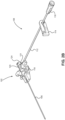
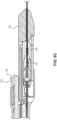
- a catheter insertion device 100 including a catheter group 102 and an insertion group 104 is illustrated.
- the insertion group 104 may be separated from the catheter group 102 following partial insertion of a catheter 106 in the vasculature of a patient.
- the catheter group 102 also includes an extension line assembly 108 in fluid communication with the catheter 106.
- the extension line assembly 108 may be connected to a fluid source or an aspiration device.
- the insertion group 104 includes a handle 110 that is initially connected to the catheter group 102 and that facilitates the insertion of the catheter 106 in the vasculature of the patient.
- FIG. 2A illustrates an exploded view of the separate components of the catheter group 102 of the catheter insertion device 100.
- FIG. 2B a partially transparent perspective view of the assembled catheter group 102 of the catheter insertion device 100 is illustrated.
- the catheter group 102 includes an extension line assembly 108 that includes an elongated extension line 112, an extension line clamp 114, and an extension line hub 116.
- a vent plug as shown in FIG. 1A , may further be attached to the extension line hub 116 during insertion of the needle and then removed prior to use by the practitioner, i.e. before the practitioner connects a syringe to the extension line hub 116.
- the elongated extension line 112 defines an elongated lumen that is in fluid communication with the lumen defined by the catheter 106 through the lumen defined by a rigid hub 120.
- the extension line clamp 114 is received around the elongated extension line 112 and may be slid in a direction perpendicular to the longitudinal axis of the elongated extension line 112 to pinch the elongated extension line 112 closed. When the extension line clamp 114 pinches the elongated extension line 112, fluid is prevented from flowing beyond the extension line clamp 114 either distally towards the catheter 106 or proximally towards the extension line hub 116.
- the extension line hub 116 defines a lumen that is in fluid communication with the lumen defined by the elongated extension line 112.
- the lumen defined by the extension line hub 116 may be tapered from its proximal end towards its distal end, while in other implementations, the lumen defined by the extension line hub 116 may have a uniform diameter.
- the proximal end of the extension line hub 116 includes a connector, such as a threaded luer lock, for connection to a fluid source or an aspiration device.
- the fluid source may be a syringe or an intravenous bag, among others.
- the catheter group 102 includes the elongated catheter 106 that is connected to a catheter hub 118.
- the proximal end of the elongated catheter 106 connects to the distal end of the catheter hub 118.
- the rigid hub 120 is partially received within the proximal end of the catheter hub 118.
- the rigid hub 120 receives a seal 218 that acts as a valve within an internal cavity defined by the rigid hub 120.
- the proximal end of the rigid hub 120 is sealed by a rigid hub cap 124.
- the proximal end of the rigid hub cap 124 has an opening that allows the needle cannula 130 and the guidewire 132 to pass through the rigid hub cap 124 to the seal 218.
- the elongated catheter 106 defines an elongated lumen that is at least partially received within the vasculature of the patient.
- the catheter hub 118 defines a tapered cavity that is in fluid communication with the lumen defined by the elongated catheter 106 and the lumen defined by the rigid hub 120.
- the rigid hub 120 also includes a side port 121 for receiving the elongated extension line 112 of the extension line assembly 108.
- the lumen defined by the side port 121 is in fluid communication with the lumen defined by the elongated extension line 112.
- the seal 218 is a multi-piece seal, as described in greater detail below. In other implementations, the seal may be one-piece seal, as described in U.S. Patent Application No. 14/306,698, filed June 17, 2014 ,.
- the seal 218 is enclosed by the rigid hub 120 and the rigid hub cap 124.
- the catheter group 102 may not include the extension line assembly 108 and the fluid source or aspiration device can be connected to a proximal end of the rigid hub 120.
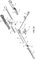
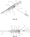
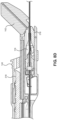
- FIG. 3A an exploded view of the separate components of the insertion group 104 of the catheter insertion device 100 is illustrated along with an assembled view of the catheter group 102.
- FIGS. 3B and 3C illustrate a perspective view and a side view, respectively, of the assembled catheter group 102 and insertion group 104 of the catheter insertion device 100.
- the insertion group 104 includes the handle 110 that is made up of a right housing 126 and a left housing 128 that are connected together. Top arm 127 and bottom arm 129 are formed in the distal region of the handle 110.
- a needle cannula 130 is held within the handle 110 and a guidewire 132, which slides through the lumen defined by the needle cannula 130, is also held within the handle 110.
- the needle cannula 130 may be anchored within the handle 110 by an interference fit within an inner channel defined by the handle 110, by an adhesive, by a threaded connection, or the like.
- the needle cannula 130 may be, for example, a 24 gauge needle.
- a needle safety clip 134 is placed around the outer surface of the needle cannula 130 to cover the sharp needle tip 131 following separation of the insertion group 104 from the catheter group 102.
- a needle guard 137 covers the portion of the needle cannula 130 extending from the handle 110 before initial use of the catheter insertion device 100.
- a first actuator such as a slider 138, is connected to the top of the handle 110 and to the guidewire 132 and slides the guidewire 132 relative to the handle 110 in both proximal and distal directions.
- the guidewire 132 may be a spring wire guide, such as a coiled or a coil-less spring wire guide. The length of the guidewire 132 is selected such that, before the slider 138 is actuated, the distal end of the guidewire does not extend beyond the sharp needle tip 131 of the needle cannula 130.
- the guidewire 132 may have a variable stiffness, as discussed in further detail below.
- the guidewire 132 may have an outer diameter that is substantially uniform and less than or equal to 0.010 inches (0.0254 centimeters).
- the guidewire 132 has an outer diameter that is less than or equal to 0.010 inches when the needle cannula 130 is a 24 GA needle and the elongated catheter 106 is a 22 GA catheter, so that the guidewire 132 may fit within the lumen defined by the 22 GA catheter.
- the guidewire 132 may have a varying diameter that narrows distally, such that the diameter of the guidewire 132 is the smallest at a distal end of the guidewire 132.
- the larger diameter section is immediately distal to the needle 130, which helps to guide the catheter 106 during advancement and also directs the catheter's movement during the initial part of the advancement.
- the distal tip of the guidewire 132 has a small outer diameter so that it is sufficiently flexible to help the guidewire 132 travel a tortuous path out of the needle 130 and into the lumen of the vessel.
- the guidewire also comprises a large diameter tip, such as a tip shaped like a ball so that it is not sharp. Such a large ball-shaped tip helps the clinician determine whether the entire guidewire is removed after use, since the clinician can see if the ball is there, thus indicating that no piece of the guidewire was left behind.
- the ball-shaped tip at the distal end of the guidewire 132 is not sharp so as to avoid puncturing a patient's vasculature during operation.
- the guidewire 132 may be made of a metal, such as a metal alloy.
- the guidewire 132 may be made of an alloy of nickel and titanium.
- the guidewire 132 may be coated with polysulfones, polyfluorocarbons, polyolefins, polyesters, polyurethanes, blends and/or copolymers.
- a second actuator such as a release 140, is also connected to the handle 110 of the insertion group 104 and to the catheter group 102.
- the release is configured to slide the catheter group 102 relative to the handle 110 in a distal direction.
- the release 140 includes a proximal arm 174 having an enlarged proximal end 141.
- a needle support 142 is attached to a proximal region of the handle 110 and swings upward and downward relative to the handle 110. In particular, the needle support 142 is rotationally coupled to the top arm 127 by a pivot member 144.
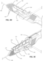
- a catheter advancer base 318 is removably connected to the catheter hub 118 and configured to slidably engage the bottom arm 129 of the handle 110, as illustrated in FIG. 3D .
- the needle support 142 may comprise a rigid plastic material to support the needle cannula 130 from bending during insertion into a patient's vasculature.
- the needle support 142 includes two parallel walls 143 separated by a distance slightly greater than the outer diameter of the elongated catheter 106 in which the needle cannula 130 passes in order to stabilize lateral movement of the needle cannula 130 during insertion of the needle in the vasculature of the patient. This stabilization is especially important for insertion of the needle relatively deep in the tissue of the patient, such as within an organ of the patient.
- the needle support may further include a textured outer surface to aid gripping by a practitioner during insertion of the catheter into the vasculature of a patient.
- a textured outer surface include various patterns of protrusions, divots, grooves, channels and bumps, among others.
- the textured surface may be formed of a different material, such as rubber, or may be formed as a roughened surface directly on the needle support 142.
- such examples of a textured surface may also be added to regions of the catheter advancer base 318, such as to a grip arm 321 or grip recess 322, among other areas, in order to aid with gripping.
- the needle support 142 also includes a top portion 147 that abuts the bottom surface of the slider 138 before the slider is slid proximally in order to prevent swinging of the needle support 142 while the catheter insertion device 100 is being inserted in the vasculature of the patient.
- a lip 149 may be provided on the needle support 142 that defines a seat region configured to hook around a distal end of the bottom arm 129 of the housing in order to prevent the needle 130 and/or the catheter 106 from popping out of the needle support 142 prematurely.
- the needle support 142 may comprise a trapezoidal or other geometric shape, and may have an extended longitudinal length, for example 2 cm, configured to provide additional support to the catheter.
- the needle support 142 is free to swing about a pivot member 144 when the slider 138 is retracted to the extent in which it no longer abuts the top portion 147 of the needle support.
- the catheter advancer base 318 is configured to receive the catheter hub 118 of the catheter group 102, as will be discussed in greater detail below.
- a retaining member, such as a protruding clip 323, is provided on the catheter advancer base 318 and is configured to further secure the wings of the catheter hub 118 to help retain the catheter hub 118 to the catheter advancer base 318 during deployment.
- the needle guard 137 includes an open channel 260 defined by two parallel side walls 262. A bottom longitudinal feature and a top longitudinal feature between the parallel side walls 262 secure around the needle cannula 130. As such, the bottom and top longitudinal features are spaced apart by a distance slightly greater than the outer diameter of the catheter 106.
- a tab 268 may be provided at the proximal end of the needle guard 137 to allow the practitioner to initially lift the needle guard 137 out of contact with the slider 138, and then push the needle guard 137 distally until the proximal ends of the bottom and top longitudinal features are distal of the sharp needle tip 131. At this point, the needle guard 137 disengages from the insertion group 104 and may be removed to expose the sharp needle tip 131.
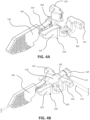
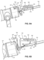
- FIG. 4A the catheter advancer base 318 and the needle support 142 are shown isolated from the rest of the catheter insertion device 100.
- FIG. 4B shows the catheter group 102 engaged with the catheter advancer base 318 and the needle support.
- An upper surface of the catheter advancer base 318 includes a catheter seat 319 configured to matingly receive the catheter hub 118.
- the retaining member 323 may be configured to allow the catheter hub 118 to securely snap into the catheter seat 319.
- a pair of spaced apart fasteners, such as pins 320, are provided within the catheter seat 319 for connecting to respective connector holes on each wing section, which extend outwardly on opposing sides of the catheter hub 118.
- the catheter hub 118 stays connected to and moves with the catheter advancer base 318 when the catheter advancer base is advanced distally during the catheter insertion procedure, as will be discussed in detail below.
- the catheter advancer base 318 may be disconnected and removed from the catheter hub 118 during dressing of the catheter 106 to a patient.
- the catheter advancer base 318 is also configured to stay with the catheter 106 during advancement and may disconnected therefrom during dressing.
- a longitudinal slide groove provided on the bottom surface of the catheter advancer base 318 defines a guide track that is configured to slidingly engage the bottom arm 129 of the housing. This guide track is configured to create a sliding motion of the catheter advancer base 318 along the bottom arm 129 and also prevent twisting of the catheter advancer base 318 and catheter hub 118 about their longitudinal axis during such sliding motion when they are advanced forward during catheter insertion.
- a grip arm 321 is provided on each side of the catheter advancer base 318, and a grip recess 322 is also provided on each side of the catheter advancer base 318.
- the grip arms 321 and grip recesses 322 allow for alternate grip positions of the catheter advancer base 318 by a practitioner, including a choked up hand grip position. For instance, in such a choked up hand position, the user may grip the catheter insertion device 100 using one hand by placing a thumb in the grip recess 322 located on a first side of the catheter advancer base 318, and a middle finger in the grip recess 322 located on an opposite second side of the catheter advancer base 318. The user's index finger may then be curled up so that it can manipulate the slider 138.
- the catheter advancer base 318 may be symmetric about its longitudinal axis to allow for both right-handed and left-handed placement by a user.
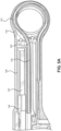
- the handle 110 includes a looped proximal end 151 through which the guidewire 132 passes.
- the guidewire 132 passes through the channel 153 defined by the handle 110.
- the diameter of the channel 153 is slightly greater than the diameter of the guidewire 132 so that the guidewire 132 stably passes through the channel 153.
- the slider 138 can be slid by a finger, such as the index finger in overhand operation or the thumb in underhand operation, of a practitioner proximally and distally within a chamber 157 defined by the handle 110.
- the chamber 157 is sized to be slightly larger than the slider 138 to stabilize the movement of the slider 138 within the chamber 157.
- proximal movement of the slider 138 translates into distal movement of the distal tip of the guidewire 132 and vice versa.
- the looping of the guidewire 132 also enables one-handed operation of the catheter insertion device 100 while maintaining continuous grip of the gripping features 148 of the handle 110.
- the looping of the guidewire 132 reduces the likelihood of piercing the vasculature of the patient during advancement of the guidewire 132 due to the force of the practitioner being indirectly applied to the guidewire 132.
- the handle 110 includes gripping features 148 that help the practitioner grip the handle 110 of the catheter insertion device 100.
- a right-handed practitioner can, for example, grip the gripping feature 148 on the left housing 128 using his thumb and grip the gripping feature 148 on the right housing using his middle finger.
- a left-handed practitioner can, for example, grip the gripping feature 148 on the left housing 128 using his middle finger and grip the gripping feature 148 on the right housing using his thumb.
- the handle 110 can be gripped by the practitioner overhand or underhand using the same fingers.
- the gripping feature 148 may comprise a plurality of depressed lines, grooves, corrugations, projections, or a roughened surface, among others, formed on the outer surface of the handle 110.
- raised lines may be formed in place of the depressed lines, a textured surface may be formed, a plurality of bumps may be formed, or a different material, such as rubber, may be provided over the region of the handle 110 corresponding to the gripping features 148.
- the bottom opening 152 is sized to receive the rigid hub cap 124 of the catheter group 102. In particular, the diameter of the bottom opening 152 is slightly greater than the diameter of the rigid hub cap 124.
- the middle opening 154 is sized to receive the guidewire 132 and the needle cannula 130, and the top opening 156 is sized to receive the slider 138 and the proximal arm 174 of the release 140.
- the top opening 156 includes a wider bottom region that receives the slider 138 and a narrower top region that receives the proximal arm 174 of the release 140.
- the bottom opening 152 and the middle opening 154 are separated by a portion of the handle 110, whereas the middle opening 154 and the top opening 156 are not separated to allow a bottom arm 158 of the slider 138 to slide within middle opening 154, as explained in greater detail below.
- the slider 138 includes a bottom arm 158 extending from the bottom of the slider 138 in a direction perpendicular to the longitudinal axis of the slider 138.
- the bottom arm 158 includes a through hole 160 that receives the proximal end 133 of the guidewire 132.
- the proximal end 133 may include a ball 162 to anchor the tip of the proximal end of the guidewire 132 in place.
- the through hole 160 has an internal diameter that is slightly larger than the outer diameter of the guidewire 132 but slightly smaller than the diameter of the ball 162 formed at the tip end of the guidewire 132.
- the guidewire 132 is therefore secured within the through hole 160 by an interference fit.
- the through hole 160 does not extend along the entirety of the length of the bottom arm 158, such that the distal end of the through hole 160 is closed.
- the ball 162 is secured within the through hole 160 by an interference fit, in some implementations, the ball 162 may be secured by an adhesive, by a threaded connection, or the like.
- the slider 138 includes one or more grips 164 that allow a finger, such as the index finger in an overhand operation or the thumb in an underhand operation, of the practitioner to predictably actuate the slider 138 in either a distal or proximal direction.
- the grips 164 may be shaped like arrows that point in the proximal direction. Adjacent to each grip 164 may be an indicator 166, such as a number, that indicates a relative extension of the guidewire 132 distally from the sharp needle tip 131.
- the guidewire 132 may further comprise a variable stiffness that facilitates insertion of the catheter 106 into the vasculature of a patient.
- the guidewire 132 may comprise various segments, such as a first segment defining a thin section of increased flexibility, a second segment defining a tapered transitioned section, and a third segment defining a thick and rigid section that assists the catheter 106 in following bends in the guidewire 132.
- the third segment which is nearest to the catheter 106 when the variable stiffness guidewire is fully extended, has the most stiffness which helps the catheter more easily follow any bends of the guidewire during insertion into a patient's vasculature.
- the stiffness gradually decreases towards the distal tip of the guidewire, such that the first segment is the most flexible region since it has the smallest diameter, which may be, for example, between .005 in and .006 in.
- the increased flexibility of the first segment allows it to easily bend upon entry into the vasculature in order to minimize piercing through the vasculature wall.
- the ball-shaped distal tip of the guidewire 132 also helps minimize such piercing through the vasculature wall.
- the length of the segment of the guidewire may vary. In one implementation, for example, the length of the first and third segments may be approximately 1.5 cm, and the length of the second segment may be approximately 1.0 cm.
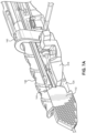
- FIG. 7A shows a portion of the catheter insertion device depicting the release 140 and the catheter advancer base 318
- FIG. 7B shows a portion of the catheter insertion device depicting the release 140 without the catheter advancer base 318.
- the distal side of the release 140 includes a notch 168 configured to receive the side port 121 of the rigid hub 120.
- the release 140 is sized to be received from around the bottom arm 129 to the slider 138.
- the notch 168 is sized to be slightly larger than the diameter of the side port 121 to stably secure the side port 121.
- the release 140 includes a continuous side wall 170. If the practitioner's finger were to push down onto the slider 138 or top arm 127 of the handle 110 while the needle cannula 130 is still in the vasculature of the patient, the resulting downward movement of the needle cannula 130 may cause damage to the vasculature of the patient. As such, the release 140 includes a distal lip 172 that extends radially outward from the release 140 in order to help prevent the practitioner's finger from slipping past the distal end of the release 140.
- the release 140 also includes a proximal arm 174 having an enlarged proximal end 141.
- the proximal arm 174 slides within the top opening 156 of the handle 110.
- the enlarged proximal end of the release 140 is dimensioned to be larger than the top opening 156 so that distal movement of the release 140 is limited to the length of the proximal arm 174, and so that the release 140 does not separate from the handle 110.
- the release 140 may also include a grip 176 that allows a finger, such as the index finger in an overhand operation or the thumb in an underhand operation, of the practitioner to predictably actuate the release 140 in either a distal or proximal direction.
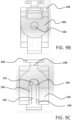
- FIG. 8A a partially transparent perspective view of a region of the assembled catheter insertion device 100 is illustrated.
- the bottom arms 129 of the right housing 126 and the left housing 128 abut against one another to support the weight of the catheter hub 118.
- the top arms 127 of the right housing 126 and the left housing 128 are spaced apart by a distance slightly greater than the width of the needle support 142 to allow the needle support 142 to swing upwards during removal of the catheter group 102.
- the outer surface of each opposite spaced apart parallel wall 143 of the needle support 142 includes a pivot member 144, such as a hinge, pivotally connected to the corresponding inner surface of each spaced apart top arm 127 of the handle.
- the needle support 142 includes two parallel walls 143 that are perpendicular to the plane of the top surface of the bottom arms 129. As explained above, the parallel walls 143 are spaced apart by a distance slightly greater than the outer diameter of the elongated catheter 106 to stabilize the needle cannula 130 during insertion into the vasculature of the patient. In various implementations, the parallel walls 143 of the needle support 142 may be sized to mate with the catheter or needle gauge size, such as 18 ga, 20 ga, or 22 ga, among others.
- Both top arms 127 also include a groove 178 configured to receive a corresponding tongue of the needle guard 137. Such a tongue and groove connection stably secures the needle guard 137 to the handle 110 to protect the catheter before use of the catheter insertion device 100.
- FIGS. 8A-8F illustrate various operating positions of the catheter insertion device 100 during advancement of the catheter group 102 from the insertion group 104.
- the top portion 147 of the needle support 142 abuts the bottom surface of the slider 138 to block the needle support 142 from swinging upward which in turn blocks the catheter advancer base 318 from moving, thus locking the release 140 from being actuated in order to retain the catheter group 102 in place between the needle support 142 and the release 140.
- the top surface 147 of the needle support 142 becomes free since it no longer abuts the slider.
- the release 140 becomes unlocked such that pushing it distally toward the needle support 142 urges the catheter advancer base 318 distally into contact with the needle support 142.
- the catheter advancer base 318 accordingly urges the needle support 142 to swing upward about the pivot member 144, thus creating a clearance for the entire catheter group 102 to be disconnected from the insertion group 104, as shown in FIG. 8F , so that the catheter 106 can be advanced forward into the patient's vasculature.
- the distal end 139 of the slider 138 extends beyond the distal end of the top arm 127 and, as such, extends distally along a portion of the needle support 142 without extending beyond the needle support.
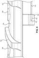
- FIG. 8B which illustrates a cross-sectional view of the region of the assembled catheter insertion device 100 along the center longitudinal plane of the handle 110, the needle support is oriented in a support position such that the bottom surface of the slider 138 abuts against the top portion 147 of the needle support 142 before the slider 138 is slid proximally in order to prevent the needle support 142 from swinging out of engagement with the catheter prior to being inserted in the vasculature of the patient.
- the needle support 142 blocks the catheter advancer base 318 and the catheter group 102 from moving forward.
- a portion of the catheter 106 proximate to the distal end of the needle support 142 is supported to resist force from three directions such as from the bottom, the left side, and the right side.
- a portion of the catheter 106 proximate to the proximal end of the needle support 142 is supported by the rigid catheter advancer base 318 to resist force from a fourth direction, such as from the top.
- the needle support 142 thus provides sufficient support to the catheter 106 in order to improve its rigidity in order to avoid excessive bending during insertion into the vasculature of a patient.
- a lip 149 is provided on the bottom of the needle support 142 and is configured to hood around a distal end of the bottoms arms 129 of the handle in order to prevent the catheter group 102 from popping out accidentally during use. Further, when the needle support 142 is oriented in the support position, the catheter advancer base 318 and the catheter hub 118 remain nested between the top and bottom arms 127, 129 of the housing 110, and between the release 140 and the needle support 142 to retain the catheter group 102 during use.
- FIG. 8C illustrates a cross-sectional view of the region of the assembled catheter insertion device 100 along the center longitudinal plane of the handle 110 following actuation of the slider 138 by the practitioner.
- the distal end 139 of the slider 138 is slid proximal of the needle support 142 so that the top portion 147 no longer abuts the bottom surface of the slider 138 and is free to swing upwards as the catheter group 102 is separated from the insertion group 104.
- FIG. 8D illustrates a cross-sectional view of the region of the assembled catheter insertion device 100 along the center longitudinal plane of the handle 110 following actuation of the release 140 by the practitioner.
- the practitioner may advance the catheter without using the release 140.
- the release 140 is pushed forward toward the distal end of the handle such that it correspondingly pushes the rigid hub 120 distally so that the catheter advancer base 318 contacts the needle support 142 and urges the needle support 142 to swing upward about the pivot members 144.
- the release 140 may be pushed forward until it reaches a stop position, after which the practitioner may continue advancing the catheter group 102 by gripping the catheter advancer base 318 and moving it forward.
- the practitioner may grip the extension line 108, or more particularly an arm of the rigid hub that contains the extension line inside of it, to advance the catheter group 102 forward.
- a practitioner may grip each grip recess 322 of the catheter advancer base 318 in a choked up position in order to facilitate advancement of the catheter advancer base 318.
- the needle support 142 continues to swing out of the way of the catheter advancer base 318 and catheter hub 118 during advancement thereof.
- the needle support 142 is therefore moved out of the path of the catheter advancer base 318 and the catheter hub 118 in order to allow the distal end of the catheter advancer base 318 and the catheter hub 118 to extend distally beyond the needle support 142.
- the catheter advancer base 318 and the catheter hub 118 thus initially abut the needle support 142, and distally move past the needle support 142 once the needle support 142 is urged by the catheter advancer base 318 to swing upward to provide clearance for full deployment of the catheter group 102, as shown in FIG. 8F .
- the catheter group is advanced distally such that the catheter group 102 is distal of the distal end of the handle 110.
- the needle safety clip 134 is still mounted to the rigid hub cap 124, as explained below.
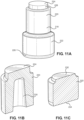
- FIG. 9A a perspective view of the needle safety clip 134 mounted to the rigid hub 120 is illustrated.
- FIG. 9B a rear view of the needle safety clip 134 is illustrated.
- FIG. 9C a front view of the needle safety clip 134 is illustrated.
- the needle safety clip 134 includes a proximal wall 180 that includes a round aperture 182 having a diameter slightly greater than the outer diameter of the needle cannula 130.
- the round aperture 182 may have a sharp inner surface to grip the outer surface of the needle cannula 130 when the needle cannula 130 is at an angle with respect to the central axis of the round aperture 182.
- the sharp inner surface of the round aperture 182 digs into the outer surface of the needle cannula 130 when the needle cannula 130 is tilted with respect to the needle safety clip 134, as shown in FIG. 9D , to prevent movement of the needle cannula 130 with respect to the needle safety clip 134.
- a top wall 184 extends distally of the proximal wall 180 and defines a top opening 186.
- the top opening 186 allows the spring arm 188 to extend partially above the top wall 184 in its compressed state, as shown in FIG. 9A .
- the spring arm 188 is illustrated having a C-shape. However, the spring arm 188 may be designed to have other shapes that are resilient and may be shaped to be, for example, stepped, blocked, jagged, or amorphous.
- the top distal portion of the spring arm 188 is connected to the distal bottom surface of the top wall 184 to secure the spring arm 188 to the rest of the needle safety clip 134.
- the spring arm 188 may be made of any flexible material, such as, for example, plastic, stainless steel, aluminum or titanium.
- the spring arm 188 may be made of the same material as the rest of the needle safety clip 134 or made of a different material having the desired characteristics.
- a first distal wall 190 extends downward from the distal end of the top wall 184 and defines a first distal channel.
- a second distal wall 194 curves upward from the first distal wall 190 and defines a second distal channel.
- a narrow tab 198 extends distally from the distal end of the second distal wall 194 and a broad tab 200 extends distally from the narrow tab 198.
- the narrow tab 198 is received within a narrow recess 202 at the top of the rigid hub cap 124 and the broad tab 200 is received within a broad recess 204 at the top of the rigid hub cap 124 to mount the needle safety clip 134 to the rigid hub cap 124.
- the narrow tab 198 prevents lateral movement of the needle safety clip 134 while broad tab 200 prevents longitudinal movement of the needle safety clip 134.
- the first distal wall 190 defines a channel having a round top region 191 and a rectangular bottom region 192.
- the diameter of the round top region 191 is slightly larger than the outer diameter of the needle cannula 130 to allow the needle cannula 130 to slide through the round top region 191 with low friction and to prevent lateral movement of the needle cannula 130.
- the rectangular bottom region 192 has a width that is less than the outer diameter of the needle cannula 130 to both keep the safety from springing upward until the needle tip is between the first distal wall and the second distal wall and block the needle cannula 130 from being able to extend distally past the second distal wall 194, as explained in greater detail below.
- the second distal wall 194 also includes a round top region 195 that has a diameter that is greater than the outer diameter of the needle cannula 130 and a rectangular bottom region 196.
- the width of the rectangular bottom region 196 may be equal to the diameter of the round top region 195 to allow the needle cannula 130 to move downward relative to the needle safety clip 134 under force of the spring arm 188.
- FIG. 9D a perspective view of the needle safety clip 134 released from the rigid hub 120 is illustrated.
- the needle cannula 130 After the needle cannula 130 is withdrawn from the rigid hub 120, it passes proximally through the round top region 195 of the second distal wall 194 and then through the round top region 191 of the first distal wall 190.
- the round top region 191 does not stabilize the needle cannula 130 (that is, once the width of the sharp needle tip, Wn, becomes smaller than the width of the rectangular bottom region 192)
- the needle safety clip 134 is free to tilt relative to the needle cannula 130.
- the spring arm 188 then decompresses, as shown in FIG. 9D , to push the needle safety clip 134 upward.
- the needle cannula 130 is still within the round aperture 182, it is gripped by the sharp inner edges of the round aperture 182, which prevents longitudinal movement of the needle cannula 130 with respect to the needle safety clip 134.
- the first distal wall 190 and the second distal wall 194 cover the sharp needle tip 131 and protect the practitioner from potential needle pricks.
- FIG. 9E a perspective view of the sharp needle tip 131 of the needle cannula 130 is illustrated.
- the sharp needle tip 131 may be formed by back grinding as illustrated, or in other implementations, the sharp needle tip 131 may have a lancet tip.
- the sharp needle tip 131 tapers in the distal direction such that the width W n of the sharp needle tip 131 at a plane along the sharp needle tip 131 is equal to the width of the rectangular bottom region 192.
- the needle cannula 130 cannot extend distally past the first distal wall 190 beyond that plane where the sharp needle tip 131 has the width W n when the needle safety clip 134 is released from the rigid hub 120 because the needle cannula 130 is wider than the rectangular bottom region 192 proximal of that plane.
- the length L n may still extend distally beyond the first distal wall 190 because the needle cannula 130 is thinner than the rectangular bottom region 192 distal of that plane. Therefore, as shown in FIG.
- the needle safety clip 134 is designed so that the distance D c between the first distal wall 190 and the second distal wall 194 in the axis aligned with the longitudinal axis of the needle cannula 130 is greater than the length L n .
- the needle cannula 130 may further comprise a swage 270 having a pressed area of the metal tube near the distal tip of the needle.
- the swage may have a substantially oval-shaped, or ellipse-shaped, cross sectional bulge that differs from the round cross section of the rest of the needle.
- the major diameter of the oval-shaped swage 270 is smaller than the cut out portions of the first and second distal walls 190, 194 of the safety latch 134, but is larger than the hole 182 in the proximal wall 180. This arrangement further ensures the safety clip 134 cannot be pulled distally off the tip of the needle.
- the minor diameter of the oval-shaped swage is larger than the width of the rectangular bottom region cut out 192 in the first distal wall of the safety latch. This ensures that the safety would not spring upward when the swage passes by the first distal wall 190 even if the rectangular bottom region 192 slot of the safety is parallel to the swage instead of being perpendicular, as it normally is.
- the inner diameter of the swage 270 is greater than the outer diameter of the guidewire 132 so that the guidewire 132 can pass therethrough.
- FIGS. 10A-B partially transparent side views of the catheter insertion device 100 during separation of the catheter group 102 are illustrated.
- the slider 138 is initially slid proximally to provide clearance to allow the needle support 142 to swing upwards, and then the release 140 is slid distally to push the catheter advancer base 318 forward.
- the practitioner can then fully advance the catheter into the patient, i.e. until the distal end of the catheter hub 118 almost touches the skin.
- the practitioner then uses the hand that is not grasping the handle 110 to stabilize the catheter group 102.
- the practitioner can use his non-dominant hand to grasp the catheter hub 118 and/or the rigid hub 120 to stabilize the rigid hub 120 at a constant position within the vasculature of the patient. The practitioner can then pull the insertion group 104 proximally to remove the needle cannula 130 from the catheter group 102.
- the insertion group 104 is pulled proximally to the point where the sharp needle tip 131 of the needle cannula 130 is proximal of the second distal wall 194, but still distal of the first distal wall 190.
- the plane where the sharp needle tip 131 has the width W n is still distal of the first distal wall 190 and the needle cannula 130 is stabilized within the round top region 191.
- the width, Wn, of the sharp needle tip 131 is less than the width of the rectangular bottom region 192 and, therefore, the needle safety clip is free to tilt relative to the needle cannula.
- the spring arm 188 then decompresses to tilt the needle safety clip upward, so that the second distal wall 194 and/or the first distal wall 190 cover the sharp needle tip 131.
- the seal 218 is a two-part seal that includes a proximal part 220 and a distal part 222.
- the proximal part 220 has a flat proximal face 224 and a proximal region 228 having a reduced diameter.
- the proximal part 220 defines an inner cavity 230 that extends along a majority of the longitudinal axis of the proximal part 220.
- the inner cavity 230 reduces the surface area of the seal 218 that the needle cannula 130 contacts, thereby reducing the frictional forces applied during advancement of the catheter group and removal of the needle cannula 130.
- lubricant may be added the cavity 230 to further reduce these frictional forces.
- the cavity 230 also provides empty space for the displaced seal material volume to move into when the cannula is inserted into the seal during the shelf life of the device, i.e. prior to removal of the cannula. This prevents a small portion of the seal material from being displaced out the back of the rigid cap of the catheter or distally into the catheter, i.e. inside the rigid catheter hub.
- the distal part 222 is solid and includes a proximal region 232 of reduced diameter.
- the diameter of the proximal region 232 is slightly smaller than the diameter of the inner cavity at the distal end of the proximal part 220 to prevent lateral movement of the distal part 222 relative to the proximal part 220 when the seal 218 is assembled within the rigid hub 120 and the rigid hub cap 124.
- the distal part 222 also has a tapered distal region with a diameter that reduces distally.
- the seal 218 may be made of a resilient material, such as, for example, silicon, rubber, polyisoprene, or the like.
- FIG. 11D a partial cross-sectional view of the assembled rigid hub 120, two-part seal 218, and rigid hub cap 124 taken along the plane defined by the diameter of the rigid hub 120 and the longitudinal axis of the side port 121 is illustrated.
- the proximal region 228 having the reduced diameter is compressed within the rigid hub cap 124 to force the seal material radially inward in response to pressure applied to the flat distal face 226.
- the flat distal face 226 is flush with the distal end of the rigid hub cap 124 to allow for complete evacuation of the inner volume of the rigid hub 120 when flushing the catheter insertion device 100.
- the distal seal diameter is larger than the diameter of the mating cavity in the rigid hub. This helps to generate a compression force to prevent air or fluid leakage after the needle/cannula is removed during routine use of the catheter by the practitioner, such as for drawing blood or injecting fluid.
- the radiused portion on the distal seal (in the middle of the assembly) mates with the corresponding radius on the inside of the rigid cap to facilitate placement and location of the distal seal, as well as resist pressure from the distal end inside the catheter body and extension line in order to keep the seal in place. Additional compression forces on the proximal side of the seal further close off the previous hole from the cannula.
- the proximal side of the seal may be flush, or just beyond flush, with the outside of the rigid cap to allow cleaning of the hub.
- the distal region of the needle cannula 130 includes one or more and, preferably, eight echogenic features.
- the echogenic features may be, for example, through holes 258 drilled within opposite sides of the needle cannula 130.
- the through holes 258 improve the echogenicity of the needle cannula 130.
- the through holes 258 are visible through the wall thickness of the elongated catheter 106 under ultrasound.
- through holes 258 allow for blood flow from within the lumen of the needle cannula 130 to the outer surface of the needle cannula 130. The blood then flows to the inner surface of the catheter 106 to allow for visual observation of the blood.
- the through holes 258 are angled relative to one another. For example, the through holes 258 are drilled 90 degrees apart from one another, as shown in FIG. 12 .
- the different angles of the through holes 258 and the number of through holes 258 results in at least two echogenic features being visible under ultrasound at all times - one echogenic feature being the sharp needle tip 131 and the other being at least one of the through holes 258.
- the two visible echogenic features enable the practitioner to know the angle of insertion of the needle cannula 130.
Landscapes
- Health & Medical Sciences (AREA)
- Life Sciences & Earth Sciences (AREA)
- Biomedical Technology (AREA)
- Pulmonology (AREA)
- Engineering & Computer Science (AREA)
- Anesthesiology (AREA)
- Biophysics (AREA)
- Heart & Thoracic Surgery (AREA)
- Hematology (AREA)
- Animal Behavior & Ethology (AREA)
- General Health & Medical Sciences (AREA)
- Public Health (AREA)
- Veterinary Medicine (AREA)
- Infusion, Injection, And Reservoir Apparatuses (AREA)
- Media Introduction/Drainage Providing Device (AREA)
Claims (15)
- Kathetereinführungsvorrichtung, Folgendes umfassend:einen Griff (110) der einen proximalen Körperabschnitt und zwei Auslegerarme (127, 129), die sich jeweils distal von dem Körperabschnitt erstrecken, aufweist;eine Nadelkanüle (130) die ein proximales Ende aufweist, das sich innerhalb des proximalen Körperabschnitts des Griffs befindet, wobei sich die Nadelkanüle distal von dem proximalen Körperabschnitt des Griffs erstreckt und einen distalen Auslegerabschnitt definiert, der teilweise zwischen den zwei Auslegerarmen (127, 129) des Griffs (110) angeordnet ist;eine Katheteranordnung (102), die abnehmbar mit dem Griff (110) gekoppelt ist und dafür konfiguriert ist, auf der Nadelkanüle (130) zu gleiten, wobei die Katheteranordnung (102) einen länglichen Katheter (106), eine Katheterbuchse (118), die mit einem proximalen Ende des länglichen Katheters (106) verbunden ist, und eine Kathetervorschubbasis (318), die lösbar mit der Katheterbuchse (118) verbunden ist, umfasst; undeine Nadelhalterung (142) die zwei parallele Wände (143) aufweist, die schwenkbar mit dem Griff (110) verbunden sind, wobei die Nadelhalterung (142) zwischen einer ersten Position und einer zweiten Position schwenkt, wobei die Nadelhalterung (142) konfiguriert ist, um die Nadelkanüle (130) auf dem Auslegerabschnitt der Nadelkanüle zu tragen wenn sich die Nadelhalterung in der ersten Position befindet und die Nadelkanüle (130) zwischen den zwei parallelen Wänden (143) der Nadelhalterung angeordnet ist, wobei die Nadelhalterung (142) das distale Vorschieben der Katheteranordnung (102) blockiert, wenn sich die Nadelhalterung in der ersten Position befindet.
- Kathetereinführungsvorrichtung nach Anspruch 1, ferner umfassend einen Führungsdraht (132) und einen Führungsdrahtaktuator (138) zum Ausfahren oder Zurückziehen des Führungsdrahts, wobei die Nadelhalterung (142) nicht aus der ersten Position wegschwenken kann, bevor der Führungsdrahtaktuator (138) bewegt wird, um den Führungsdraht (132) distal über eine Spitze (131) der Nadelkanüle (130) hinaus auszufahren.
- Kathetereinführungsvorrichtung nach einem der Ansprüche 1 oder 2, wobei die zwei Arme (127, 129) des Griffs (110) einen oberen Arm und einen unteren Arm umfassen und die Kathetervorschubbasis (318) verschiebbar mit dem unteren Arm (129) des Griffs in Eingriff steht.
- Kathetereinführungsvorrichtung nach einem der Ansprüche 1 bis 3, wobei die Kathetervorschubbasis (318) eine Führungsschiene (324) umfasst, die konfiguriert ist, um den unteren Arm (129) des Griffs (110) aufzunehmen, um die Katheteranordnung (102) in einer distalen Richtung relativ zum Griff und in einer proximalen Richtung relativ zum Griff zu bewegen, und wobei die Führungsschiene (324) ein Verdrehen der Katheteranordnung (102) während der Bewegung der Katheteranordnung (102) sowohl in distaler als auch in proximaler Richtung verhindert.
- Kathetereinführungsvorrichtung nach einem der Ansprüche 1 bis 4, wobei die Kathetervorschubbasis (318) ein Paar Greifarme (321) zum Unterstützen einer verengten Handposition durch den Benutzer einschließt.
- Kathetereinführungsvorrichtung nach einem der Ansprüche 1 bis 5, wobei die Nadelhalterung (142) schwenkbar mit einem distalen Abschnitt des oberen Arms (127) des Griffs (110) verbunden ist und konfiguriert ist, um sich bei einem Auftreffen der Kathetervorschubbasis (318) auf die Nadelhalterung (142) relativ zu dem Griff zu bewegen.
- Kathetereinführungsvorrichtung nach einem der Ansprüche 1 bis 6, wobei die Nadelhalterung (142) konfiguriert ist, um relativ zum Griff (110) um eine Schwenkachse senkrecht zu einer Achse der Nadelkanüle (130) zu schwenken.
- Kathetereinführungsvorrichtung nach einem der Ansprüche 1 bis 7, wobei die Nadelhalterung (142) ferner einen Hakenabschnitt (149) umfasst, der dafür konfiguriert ist, lösbar mit dem unteren Ende des Griffs (110) zusammenzupassen, wenn sich der Nadelabschnitt in der ersten Position befindet.
- Kathetereinführungsvorrichtung nach einem der Ansprüche 1 bis 8, ferner umfassend einen Katheteranordnungsaktuator (140), der mit dem Griff (110) verbunden ist, wobei der Katheteranordnungsaktuator (140) relativ zum Griff (110) beweglich ist, um die Katheteranordnung (102) distal relativ zum Griff zu drücken.
- Kathetereinführungsvorrichtung nach einem der Ansprüche 1 bis 9, wobei die Kathetervorschubbasis (318) ferner einen Sitzabschnitt (319) umfasst, der dafür konfiguriert ist, den Katheter und die Katheterbuchse (118) stabil zu sichern.
- Kathetereinführungsvorrichtung nach einem der Ansprüche 1 bis 10, wobei die Kathetervorschubbasis (318) ferner ein Halteelement (320, 323) umfasst, das dafür konfiguriert ist, die Katheterbuchse (118) zu sichern.
- Kathetereinführungsvorrichtung nach einem der Ansprüche 1 bis 11, wobei die Nadelhalterung (142) ferner eine strukturierte Oberfläche zur Unterstützung des Greifens umfasst.
- Kathetereinführungsvorrichtung nach einem der Ansprüche 1 bis 12, wobei die Nadelkanüle (130) ferner eine scharfe distale Spitze (131) umfasst, die sich distal vom Griff (110) erstreckt, wobei die distale Spitze einen hinterschliffenen Abschnitt aufweist, der eine graduelle Verjüngung definiert.
- Kathetereinführungsvorrichtung nach einem der Ansprüche 2, wobei der Führungsdraht (132) ferner eine variable Steifigkeit aufweist.
- Kathetereinführungsvorrichtung nach einem der Ansprüche 1 bis 14, wobei die Nadelkanüle (130) ferner eine Stauchung (270) mit einer ovalförmigen Querschnittswölbung in der Nähe einer distalen Spitze (131) der Nadelkanüle umfasst.
Priority Applications (1)
| Application Number | Priority Date | Filing Date | Title |
|---|---|---|---|
| EP24210974.2A EP4480525A3 (de) | 2017-04-13 | 2018-04-11 | Kathetereinführvorrichtung |
Applications Claiming Priority (2)
| Application Number | Priority Date | Filing Date | Title |
|---|---|---|---|
| US201762485167P | 2017-04-13 | 2017-04-13 | |
| PCT/US2018/027078 WO2018191361A1 (en) | 2017-04-13 | 2018-04-11 | Catheter insertion device |
Related Child Applications (1)
| Application Number | Title | Priority Date | Filing Date |
|---|---|---|---|
| EP24210974.2A Division EP4480525A3 (de) | 2017-04-13 | 2018-04-11 | Kathetereinführvorrichtung |
Publications (4)
| Publication Number | Publication Date |
|---|---|
| EP3609565A1 EP3609565A1 (de) | 2020-02-19 |
| EP3609565A4 EP3609565A4 (de) | 2021-01-13 |
| EP3609565B1 true EP3609565B1 (de) | 2024-11-06 |
| EP3609565C0 EP3609565C0 (de) | 2024-11-06 |
Family
ID=63791387
Family Applications (2)
| Application Number | Title | Priority Date | Filing Date |
|---|---|---|---|
| EP24210974.2A Pending EP4480525A3 (de) | 2017-04-13 | 2018-04-11 | Kathetereinführvorrichtung |
| EP18785085.4A Active EP3609565B1 (de) | 2017-04-13 | 2018-04-11 | Kathetereinführungsvorrichtung |
Family Applications Before (1)
| Application Number | Title | Priority Date | Filing Date |
|---|---|---|---|
| EP24210974.2A Pending EP4480525A3 (de) | 2017-04-13 | 2018-04-11 | Kathetereinführvorrichtung |
Country Status (7)
| Country | Link |
|---|---|
| US (3) | US10737063B2 (de) |
| EP (2) | EP4480525A3 (de) |
| JP (2) | JP6906063B2 (de) |
| CN (2) | CN114146286B (de) |
| AU (2) | AU2018251786B2 (de) |
| CA (2) | CA3172718C (de) |
| WO (1) | WO2018191361A1 (de) |
Families Citing this family (39)
| Publication number | Priority date | Publication date | Assignee | Title |
|---|---|---|---|---|
| ES2975734T3 (es) | 2015-01-29 | 2024-07-12 | Becton Dickinson Co | Catéter integrado de inserción rápida |
| JP7132633B2 (ja) | 2016-12-27 | 2022-09-07 | ヴァソニクス・インコーポレイテッド | カテーテルハウジング |
| CN114146286B (zh) * | 2017-04-13 | 2025-06-13 | 特利弗雷克斯医药公司 | 导管插入装置 |
| US11116509B2 (en) | 2017-11-10 | 2021-09-14 | Avantec Vascular Corporation | System and method for delivering an embolic device |
| US11291803B2 (en) * | 2018-01-11 | 2022-04-05 | Becton, Dickinson And Company | Catheter system with guidewire advancement element |
| US11406795B2 (en) * | 2018-07-10 | 2022-08-09 | Becton, Dickinson And Company | Delivery device for a vascular access instrument |
| WO2020109448A1 (en) * | 2018-11-28 | 2020-06-04 | B. Braun Melsungen Ag | Extended dwell and midline catheters and related methods |
| WO2020163298A1 (en) | 2019-02-05 | 2020-08-13 | Bard Access Systems, Inc. | Apparatus and methods to modulate stylet stiffness profile |
| US11364050B2 (en) * | 2019-02-27 | 2022-06-21 | Avent, Inc. | Catheter placing instrument |
| WO2020206244A1 (en) * | 2019-04-05 | 2020-10-08 | Vanderbilt University | Systems and methods for advancing a catheter to a target site |
| WO2020210488A1 (en) * | 2019-04-12 | 2020-10-15 | Teleflex Medical Incorporated | Catheter insertion apparatus with continuous visible flashback |
| KR102926052B1 (ko) | 2019-09-10 | 2026-02-10 | 바드 액세스 시스템즈, 인크. | 신속 삽입 중앙 카테터 및 그 방법(rapidly inserted central catheter and methods thereof) |
| BR112022005254A2 (pt) | 2019-09-24 | 2022-06-14 | Bard Access Systems Inc | Cateter venoso central agudo e cateter venoso inserido perifericamente integrados |
| BR112022007377A2 (pt) | 2019-10-25 | 2022-07-05 | Bard Access Systems Inc | Dispositivos de manejo de fio guia e métodos dos mesmos |
| US11382634B2 (en) | 2019-12-18 | 2022-07-12 | Avantec Vascular Corporation | Embolic device suited for ease of delivery and placement |
| CN111110988B (zh) * | 2020-01-10 | 2021-08-24 | 山东省千佛山医院 | 一种引流管潜行置入的装置 |
| KR20220131973A (ko) | 2020-01-23 | 2022-09-29 | 바드 액세스 시스템즈, 인크. | 분할 가능 카테터 도킹 스테이션 시스템(splitable catheter docking station system) |
| CA3172383A1 (en) | 2020-03-13 | 2021-09-16 | Bard Access Systems, Inc. | Guidewire-management devices and methods thereof |
| CN215135639U (zh) | 2020-03-13 | 2021-12-14 | 巴德阿克塞斯系统股份有限公司 | 导丝管理装置 |
| US12377248B2 (en) * | 2020-03-23 | 2025-08-05 | Becton, Dickinson And Company | Vascular access device assembly facilitating single-handed probe advancement with a support member |
| BR112022020408A2 (pt) | 2020-04-23 | 2022-11-22 | Bard Access Systems Inc | Cateteres centrais de inserção rápida incluindo conjuntos de cateter |
| MX2022013505A (es) * | 2020-04-27 | 2022-11-16 | Bard Access Systems Inc | Cateteres centrales de insercion rapida ("ricc") que incluyen conjuntos de cateter y metodos para los mismos. |
| JP7781778B2 (ja) | 2020-05-21 | 2025-12-08 | バード・アクセス・システムズ,インコーポレーテッド | カテーテルアセンブリを含む迅速挿入型中心静脈カテーテルおよびその方法 |
| JP7760535B2 (ja) | 2020-06-29 | 2025-10-27 | バード・アクセス・システムズ,インコーポレーテッド | 患者の血管内腔への直接挿入のためのカテーテルアセンブリ |
| CN215916122U (zh) | 2020-06-29 | 2022-03-01 | 巴德阿克塞斯系统股份有限公司 | 包括组件的可快速插入的中心导管 |
| BR112023001447A2 (pt) * | 2020-07-31 | 2023-02-14 | Bard Access Systems Inc | Cateteres centrais de inserção rápida de duas peças, introdutores para os mesmos e métodos dos mesmos |
| JP2023536720A (ja) | 2020-08-03 | 2023-08-29 | バード・アクセス・システムズ,インコーポレーテッド | 分割可能な針及び拡張カテーテル留置デバイス |
| CA3193409A1 (en) * | 2020-09-21 | 2022-03-24 | Alan Pitas | Needle bending device |
| US20230381459A1 (en) * | 2020-10-07 | 2023-11-30 | Venocare, Inc. | Intravascular catheter with integrated guide structure |
| KR20230098227A (ko) | 2020-10-28 | 2023-07-03 | 바드 액세스 시스템즈, 인크. | 강화 시스템이 구비된 카테터 배치 시스템 (catheter placement system with stiffening system) |
| US12472331B2 (en) | 2020-12-03 | 2025-11-18 | Bard Access Systems, Inc. | Needle tip blunting using a length of a guidewire |
| US12465729B2 (en) | 2020-12-15 | 2025-11-11 | Main Circle Medical Inc. | Wire and catheter placement device |
| WO2022133297A1 (en) | 2020-12-17 | 2022-06-23 | Bard Access Systems, Inc. | Rapidly insertable central catheters and assemblies |
| MX2023006864A (es) | 2020-12-21 | 2023-06-22 | Bard Access Systems Inc | Optimizacion de la via de fluido en sistemas de insercion de cateter. |
| AU2021410717B2 (en) * | 2020-12-21 | 2025-10-16 | Bard Access Systems, Inc. | Optimized structural support in catheter insertion systems |
| CN119546361A (zh) * | 2022-04-07 | 2025-02-28 | 维诺凯尔公司 | 具有一体化引导结构的血管内导管 |
| CN115501424B (zh) * | 2022-10-11 | 2025-06-17 | 山东安得医疗用品股份有限公司 | 中长期留置的外周静脉导管组件 |
| JP2026504686A (ja) * | 2023-02-02 | 2026-02-06 | ヴェノケア,インコーポレーテッド | 血管内アクセス用の案内要素システム |
| WO2026010933A1 (en) * | 2024-07-01 | 2026-01-08 | Venocare, Inc. | Vascular access device |
Family Cites Families (254)
| Publication number | Priority date | Publication date | Assignee | Title |
|---|---|---|---|---|
| US4160383A (en) | 1977-12-27 | 1979-07-10 | Will Ross Inc. | Unitary sample-vent-valve assembly |
| US4311137A (en) * | 1980-04-30 | 1982-01-19 | Sherwood Medical Industries Inc. | Infusion device |
| US4616648A (en) | 1985-01-08 | 1986-10-14 | Devices For Vascular Intervention | Device facilitating the exchange of dilatation catheters during an angioplasty procedure |
| US4809679A (en) | 1986-11-19 | 1989-03-07 | Olympus Optical Co., Ltd. | Forceps plug for endoscopes |
| US4858810A (en) | 1987-04-30 | 1989-08-22 | Heart Technology, Inc. | Quick acting pin vise for use with angiographic guidewires |
| US4895565A (en) | 1987-09-21 | 1990-01-23 | Cordis Corporation | Medical instrument valve |
| US4798594A (en) | 1987-09-21 | 1989-01-17 | Cordis Corporation | Medical instrument valve |
| US4857062A (en) | 1988-03-09 | 1989-08-15 | Medical Parameters, Inc. | Catheter introducer valve |
| US5009391A (en) | 1988-05-02 | 1991-04-23 | The Kendall Company | Valve assembly |
| US4895346A (en) | 1988-05-02 | 1990-01-23 | The Kendall Company | Valve assembly |
| US5304156A (en) | 1988-06-02 | 1994-04-19 | C. R. Bard, Inc. | Self-sealing guidewire and catheter introducer |
| US4929241A (en) | 1988-08-05 | 1990-05-29 | Kulli John C | Medical needle puncture guard |
| US5048530A (en) | 1988-08-17 | 1991-09-17 | Robert Hurwitz | Method of using an amniocentesis needle with improved sonographic visibility |
| US4977897A (en) | 1988-08-17 | 1990-12-18 | Robert Hurwitz | Amniocentesis needle with improved sonographic visibility |
| EP0436646B1 (de) | 1988-09-30 | 1994-08-31 | David S. Utterberg | Nadeleinheit mit einer schutz- und befestigungsvorrichtung |
| US4917669A (en) | 1989-02-08 | 1990-04-17 | Safetyject | Catheter inserter |
| US5081997A (en) | 1989-03-09 | 1992-01-21 | Vance Products Incorporated | Echogenic devices, material and method |
| US5135504A (en) | 1989-07-17 | 1992-08-04 | Mclees Donald J | Needle tip guard |
| US5007901A (en) | 1989-11-24 | 1991-04-16 | Shields Jack W | Intravenous catheter insertion device |
| US5053017A (en) | 1990-02-28 | 1991-10-01 | Chamuel Steven R | Hypodermic needle safety clip |
| US5057084A (en) | 1990-03-01 | 1991-10-15 | The Regents Of The University Of Michigan | Implantable infusion device |
| US5084023A (en) | 1990-03-22 | 1992-01-28 | Critikon, Inc. | Bloodless catheter with self-shielding needle |
| FR2666230B1 (fr) | 1990-09-03 | 1997-10-03 | Hospal Ind | Dispositif a aiguille a usage medical. |
| US5102394A (en) | 1990-12-19 | 1992-04-07 | Abbott Laboratories | Catheter assembly with protective shield |
| US5292310A (en) | 1990-12-27 | 1994-03-08 | Inbae Yoon | Safety needle |
| US5116323A (en) | 1991-01-22 | 1992-05-26 | Becton, Dickinson And Company | Arterial catheter |
| US5120320A (en) | 1991-02-13 | 1992-06-09 | Becton, Dickinson And Company | I.V. infusion or blood collection assembly with automatic safety feature |
| US5176647A (en) | 1991-06-03 | 1993-01-05 | Knoepfler Dennis J | Catheter device for performing a cholangiogram during a laparoscopy surgery |
| EP0592720B1 (de) | 1991-06-10 | 1998-07-29 | Cordis Corporation | Auswechselbarer Dilatationskatheter |
| US5135535A (en) | 1991-06-11 | 1992-08-04 | Advanced Cardiovascular Systems, Inc. | Catheter system with catheter and guidewire exchange |
| US5186712A (en) | 1991-08-23 | 1993-02-16 | Kansas Creative Devices, Inc. | Intravenous catheter launching device |
| IT225809Y1 (it) | 1991-08-26 | 1997-01-24 | Pio Nicoletti | Dispositivo ago sicuro atto ad annullare il pericolo di puntura accidentale del personale sanitario |
| US5325746A (en) | 1991-09-27 | 1994-07-05 | Cook Incorporated | Wire guide control handle |
| US5389100A (en) | 1991-11-06 | 1995-02-14 | Imagyn Medical, Inc. | Controller for manipulation of instruments within a catheter |
| EP0545671B1 (de) | 1991-12-03 | 1999-03-03 | Smiths Industries Plc | Nadelschutzvorrichtung |
| US5176650A (en) | 1992-02-10 | 1993-01-05 | Haining Michael L | Intravenous catheter and insertion device |
| SE470396B (sv) | 1992-12-04 | 1994-02-14 | Dicamed Ab | Ventilanordning för aseptisk injicering och uttag av medicinsk vätska i/ur behållare samt dess användning |
| US5527290A (en) | 1992-08-10 | 1996-06-18 | Zadini; Filiberto | Semi-automatic cannulation device or manually triggered self-propelled catheter cannulation device |
| DE59310202D1 (de) | 1992-11-24 | 2001-09-27 | Braun Melsungen Ag | Katheterisierungsbesteck |
| SE502537C2 (sv) | 1992-11-26 | 1995-11-06 | Boc Ohmeda Ab | Anordning vid infusionskanyl |
| US5318541A (en) | 1993-03-02 | 1994-06-07 | Cordis Corporation | Apparatus for catheter exchange in vascular dilitation |
| CA2116724A1 (en) | 1993-03-12 | 1994-09-13 | Richard A. Gambale | Windowed catheter and method of use |
| US5350363A (en) | 1993-06-14 | 1994-09-27 | Cordis Corporation | Enhanced sheath valve |
| WO1995002430A1 (en) | 1993-07-15 | 1995-01-26 | Advanced Cardiovascular Systems, Inc. | Rapid exchange type intraluminal catheter with guiding element |
| US5562619A (en) | 1993-08-19 | 1996-10-08 | Boston Scientific Corporation | Deflectable catheter |
| US5366441A (en) | 1993-09-28 | 1994-11-22 | Becton, Dickinson And Company | Catheter introducer assembly with guidewire |
| US5330438A (en) | 1993-10-08 | 1994-07-19 | Gollobin Peter J | Protective sheath for butterfly needles and IV infusion set and sheath assembly |
| US5403283A (en) | 1993-10-28 | 1995-04-04 | Luther Medical Products, Inc. | Percutaneous port catheter assembly and method of use |
| US5405323A (en) | 1994-02-22 | 1995-04-11 | Aeroquip Corporation | Catheter check valve assembly |
| US5573510A (en) | 1994-02-28 | 1996-11-12 | Isaacson; Dennis R. | Safety intravenous catheter assembly with automatically retractable needle |
| AU651308B3 (en) | 1994-03-09 | 1994-07-14 | Noble House Group Pty Ltd | Protection assembly |
| US5409464A (en) | 1994-05-13 | 1995-04-25 | Cordis Corporation | Intravascular catheter having barrier valve |
| US5738660A (en) | 1994-10-27 | 1998-04-14 | Luther Medical Products, Inc. | Percutaneous port catheter assembly and method of use |
| DE4442352C1 (de) | 1994-11-29 | 1995-12-21 | Braun Melsungen Ag | Ventilvorrichtung |
| GB9501218D0 (en) | 1995-01-21 | 1995-03-15 | Boc Group Plc | Medical devices |
| EP0827383B1 (de) * | 1995-02-28 | 2007-05-30 | Boston Scientific Corporation | Vorrichtung aus Polymer zur übertragung eines Drehmomentes |
| US5795339A (en) | 1995-03-07 | 1998-08-18 | Becton Dickinson And Company | Catheter-advancement actuated needle retraction system |
| CA2168615A1 (en) | 1995-03-07 | 1996-09-08 | Timothy J. Erskine | Catheter-advancement actuated needle retraction system |
| EP0889706A1 (de) | 1995-03-08 | 1999-01-13 | TERWILLIGER, Richard, A. | Ultraschallechonadel |
| US5766135A (en) | 1995-03-08 | 1998-06-16 | Terwilliger; Richard A. | Echogenic needle tip |
| US5599310A (en) | 1995-06-07 | 1997-02-04 | Johnson & Johnson Medical, Inc. | I.V. catheter assembly with automatic cannula tip guard |
| US5562631A (en) | 1995-06-07 | 1996-10-08 | Johnson & Johnson Medical, Inc. | Catheter arrangement with interlocking sequenced guarding members for protecting cannula |
| IL118551A (en) * | 1995-06-07 | 2004-05-12 | Johnson & Johnson Medical | Defensive cover I limited to a needle |
| KR19990072072A (ko) | 1995-12-11 | 1999-09-27 | 황,친,롱 | 가요성 익스텐더와 니이들 팁 보호기를 갖는 정맥용 카테테르 |
| US5704914A (en) | 1996-02-23 | 1998-01-06 | Stocking; John E. | Catheter placement assembly |
| US6629959B2 (en) | 1996-02-27 | 2003-10-07 | Injectimed, Inc. | Needle tip guard for percutaneous entry needles |
| EP2319556B1 (de) | 1996-02-27 | 2013-04-24 | B. Braun Melsungen AG | Nadelspitzenschutz für Subkutaninjektionen |
| GB9610682D0 (en) | 1996-05-22 | 1996-07-31 | Boc Group Plc | Medical devices |
| JP4245196B2 (ja) | 1996-07-03 | 2009-03-25 | 東郷メディキット株式会社 | 医療用穿刺具 |
| US5858007A (en) | 1996-07-03 | 1999-01-12 | C. R. Bard, Inc. | Hemostatic catheter introducer |
| CN1178707A (zh) | 1996-09-27 | 1998-04-15 | 贝克顿迪金森公司 | 进入脉管的器件 |
| US6197001B1 (en) | 1996-09-27 | 2001-03-06 | Becton Dickinson And Company | Vascular access device |
| US6106473A (en) | 1996-11-06 | 2000-08-22 | Sts Biopolymers, Inc. | Echogenic coatings |
| US5974438A (en) | 1996-12-31 | 1999-10-26 | Compaq Computer Corporation | Scoreboard for cached multi-thread processes |
| US5954698A (en) | 1997-01-08 | 1999-09-21 | Vadus, Inc. | Catheter apparatus having valved catheter hub and needle protector |
| DE69824734T2 (de) | 1997-08-11 | 2005-07-14 | Eric Oliver Macleod Smith Family Trust | Katheterventil |
| US8211070B2 (en) | 1997-08-20 | 2012-07-03 | B. Braun Melsungen Ag | Spring clip safety IV catheter |
| US6616630B1 (en) | 1997-08-20 | 2003-09-09 | B. Braun Melsungen A.G. | Spring clip safety IV catheter |
| US6117108A (en) | 1997-08-20 | 2000-09-12 | Braun Melsungen Ag | Spring clip safety IV catheter |
| US8382721B2 (en) | 1997-08-20 | 2013-02-26 | B. Braun Melsungen Ag | Spring clip safety IV catheter |
| US7125397B2 (en) | 1997-08-20 | 2006-10-24 | B. Braun Melsungen Ag | Protective device for an injection needle |
| GB9719182D0 (en) | 1997-09-09 | 1997-11-12 | Boc Group Plc | Guide wire introducer |
| US6053870A (en) | 1997-11-08 | 2000-04-25 | Angiodynamics, Inc. | Ultrasonic visible surgical needle |
| US7524306B2 (en) | 1997-11-12 | 2009-04-28 | Mdc Investment Holdings, Inc. | Catheter insertion device with retractable needle |
| US6077244A (en) | 1998-04-30 | 2000-06-20 | Mdc Investment Holdings, Inc. | Catheter insertion device with retractable needle |
| US5989224A (en) | 1998-02-23 | 1999-11-23 | Dexide Corporation | Universal seal for use with endoscopic cannula |
| US6749588B1 (en) | 1998-04-09 | 2004-06-15 | Becton Dickinson And Company | Catheter and introducer needle assembly with needle shield |
| US6652490B2 (en) | 1998-04-09 | 2003-11-25 | Becton Dickinson And Company | Catheter and introducer needle assembly with compact needle shield |
| DE29808232U1 (de) | 1998-05-07 | 1998-07-23 | Lohmann Gmbh & Co Kg, 56567 Neuwied | Kompressionsverband |
| US6547762B1 (en) | 1999-05-13 | 2003-04-15 | Mdc Investment Holdings, Inc. | Retractable needle medical device |
| US20030120214A1 (en) | 2001-03-28 | 2003-06-26 | Howell Glade H. | Blood seal having a spring-biased septum |
| US6228060B1 (en) | 1998-09-02 | 2001-05-08 | Becton, Dickinson And Company | Blood seal having a spring-biased septum |
| US6544239B2 (en) | 1998-10-16 | 2003-04-08 | Bio-Plexus Delaware, Inc. | Releasable locking needle assembly with optional release accessory therefor |
| US6213978B1 (en) | 1998-10-27 | 2001-04-10 | Cherie A. Voyten | Intravenous catheter insertion apparatus |
| US6050976A (en) | 1998-12-23 | 2000-04-18 | Specialized Health Products, Inc. | In-line retractable safety catheter needle insertion assembly |
| US6620136B1 (en) | 1999-02-18 | 2003-09-16 | Medsafe Technologies, Llc | Retractable I-V catheter placement device |
| US6287280B1 (en) | 1999-09-07 | 2001-09-11 | Merit Medical Systems, Inc. | Hemostasis valve apparatus with integral introducer |
| DE19948409C1 (de) | 1999-10-07 | 2001-04-19 | Helmut Wollschlaeger | Vorrichtung zur Handhabung wenigstens eines Führungsdrahts zur Führung eines interventionellen medizinischen Instruments oder zur Handhabung eines Katheterschafts bei interventionellen medizinischen Techniken |
| US6299602B1 (en) | 1999-11-03 | 2001-10-09 | Scan, Inc. | Apparatus and method for catheterization of blood vessels |
| DE29921084U1 (de) | 1999-12-01 | 2000-02-17 | B. Braun Melsungen Ag, 34212 Melsungen | Kurzkatheter |
| US6602240B2 (en) | 2000-02-15 | 2003-08-05 | Thomas J. Fogarty | Method and device for maintaining a seal |
| US6972002B2 (en) | 2000-04-28 | 2005-12-06 | Specialized Health Products, Inc. | Passively activated safety shield for a catheter insertion needle |
| US6699221B2 (en) | 2000-06-15 | 2004-03-02 | Vincent L. Vaillancourt | Bloodless catheter |
| CN1276781C (zh) | 2000-12-18 | 2006-09-27 | 泰尔茂株式会社 | 防护器及留置针组合体 |
| IL141574A0 (en) | 2001-02-21 | 2002-03-10 | Serpomed Ltd | Compact catheter insertion apparatus |
| JP4387105B2 (ja) | 2001-03-04 | 2009-12-16 | アイシーユー・メディカル・インコーポレーテッド | インフュージョンハブアセンブリおよび流体ライン切断システム |
| JP4996015B2 (ja) | 2001-03-12 | 2012-08-08 | メディキット株式会社 | 留置用カテーテル |
| US6902546B2 (en) | 2001-03-15 | 2005-06-07 | Specialized Health Products, Inc. | Safety shield for medical needles |
| US6984213B2 (en) | 2001-03-15 | 2006-01-10 | Specialized Health Products, Inc. | Biopsy needle device |
| US7413562B2 (en) | 2001-03-15 | 2008-08-19 | Specialized Health Products, Inc. | Safety shield for medical needles |
| US7179244B2 (en) | 2001-03-15 | 2007-02-20 | Specialized Health Products, Inc. | Resettable safety shield for medical needles |
| US7004927B2 (en) | 2001-03-15 | 2006-02-28 | Specialized Health Products, Inc. | Safety shield for medical needles |
| US6595955B2 (en) | 2001-03-15 | 2003-07-22 | Specialized Health Products, Inc. | Safety shield for medical needles |
| US6796962B2 (en) | 2001-03-15 | 2004-09-28 | Specialized Health Products, Inc. | Safety shield for medical needles |
| US6866677B2 (en) * | 2001-04-03 | 2005-03-15 | Medtronic Ave, Inc. | Temporary intraluminal filter guidewire and methods of use |
| DE20106697U1 (de) | 2001-04-18 | 2001-10-31 | B. Braun Melsungen Ag, 34212 Melsungen | Kathetereinführvorrichtung |
| US6461362B1 (en) | 2001-04-30 | 2002-10-08 | Mdc Investment Holdings, Inc. | Catheter insertion device with retractable needle |
| US6506181B2 (en) | 2001-05-25 | 2003-01-14 | Becton, Dickinson And Company | Catheter having a low drag septum |
| US6638252B2 (en) | 2001-05-25 | 2003-10-28 | Becton Dickinson And Company | Cantilever push tab for an intravenous medical device |
| US6824527B2 (en) | 2001-06-07 | 2004-11-30 | Peter Gollobin | Protective sheath for winged needles and sheath and needle assembly |
| US6565542B2 (en) | 2001-06-22 | 2003-05-20 | Minnesota High-Tech Resources | Epidural needle having a distal flare |
| US6652486B2 (en) | 2001-09-27 | 2003-11-25 | Medex, Inc. | Safety catheter |
| US6866669B2 (en) | 2001-10-12 | 2005-03-15 | Cordis Corporation | Locking handle deployment mechanism for medical device and method |
| US7429258B2 (en) | 2001-10-26 | 2008-09-30 | Massachusetts Institute Of Technology | Microneedle transport device |
| US6981965B2 (en) | 2001-10-31 | 2006-01-03 | Luther Research Partners Llc | Universal passive protector for an IV catheter |
| US6860856B2 (en) | 2002-01-11 | 2005-03-01 | Scimed Life Systems, Inc. | Echogenic surface for enhanced ultasonic visibility |
| FR2836385B1 (fr) | 2002-02-08 | 2005-03-25 | Vygon | Ensemble medical comprenant un catheter, une aiguille et son etui |
| DE20210394U1 (de) | 2002-07-04 | 2002-09-12 | B. Braun Melsungen Ag, 34212 Melsungen | Kathetereinführvorrichtung |
| DE20210509U1 (de) | 2002-07-05 | 2003-01-02 | Scheu, Rolf Rainer, 60488 Frankfurt | Vorrichtung zum Halten und Führen eines Führungsdrahtes für einen Katheter |
| US7044936B2 (en) | 2002-08-21 | 2006-05-16 | Arrow International Inc. | Catheter connector with pivot lever spring latch |
| WO2004020024A1 (en) | 2002-08-30 | 2004-03-11 | Inrad, Inc. | Localizing needle with fluid delivery |
| US20040127855A1 (en) | 2002-10-10 | 2004-07-01 | Nmt Medical, Inc. | Hemostasis valve |
| US7458954B2 (en) | 2002-11-07 | 2008-12-02 | Specialized Health Products, Inc. | Safety shield for medical needles |
| DE60330705D1 (de) | 2002-11-18 | 2010-02-04 | Bard Peripheral Vascular Inc | Gerät zum implantieren eines vorgespannten lokalisierungsdrahtes |
| US7125396B2 (en) | 2002-12-30 | 2006-10-24 | Cardinal Health 303, Inc. | Safety catheter system and method |
| US7175610B2 (en) | 2003-03-20 | 2007-02-13 | Nipro Corporation | Protector sheath for winged-needle |
| US7544184B2 (en) | 2003-04-04 | 2009-06-09 | Cook Incorporated | Bloodless percutaneous insertion system |
| US7291130B2 (en) | 2003-04-08 | 2007-11-06 | Smiths Medical Asd, Inc. | Safety needle and catheter assembly |
| US7951121B2 (en) | 2003-07-30 | 2011-05-31 | Navilyst Medical, Inc. | Pressure actuated valve with improved slit configuration |
| FR2860162B1 (fr) | 2003-09-26 | 2006-06-02 | Becton Dickinson France | Dispositif de protection d'un appareil d'injection |
| US20050075609A1 (en) | 2003-10-01 | 2005-04-07 | Latona Patrick C. | Protective needle clips |
| US7967829B2 (en) | 2003-10-09 | 2011-06-28 | Boston Scientific Scimed, Inc. | Medical device delivery system |
| US7226434B2 (en) | 2003-10-31 | 2007-06-05 | Tyco Healthcare Group Lp | Safety shield |
| US7988664B2 (en) | 2004-11-01 | 2011-08-02 | Tyco Healthcare Group Lp | Locking clip with trigger bushing |
| US7273469B1 (en) | 2003-12-31 | 2007-09-25 | Advanced Cardiovascular Systems, Inc. | Modified needle catheter for directional orientation delivery |
| JP2007521918A (ja) | 2004-02-13 | 2007-08-09 | スミス・メディカル・エイエスディ・インコーポレーテッド | ニードル先端保護装置 |
| US7556617B2 (en) | 2004-02-26 | 2009-07-07 | Medical Components, Inc. | Catheter safety needle |
| FR2867083B1 (fr) | 2004-03-02 | 2006-05-26 | Vygon | Dispositif a lame flexible pour la mise en place d'une canule dans une veine |
| US7708721B2 (en) | 2004-04-05 | 2010-05-04 | University Of Medicine & Dentistry Of New Jersey | Vascular access needle |
| WO2005102434A2 (en) | 2004-04-26 | 2005-11-03 | Sklar, Warren | Catheter insertion apparatus with a needle tip protective system |
| WO2005107843A1 (en) | 2004-04-30 | 2005-11-17 | C.R. Bard, Inc. | Valved sheath introducer for venous cannulation |
| WO2005113051A2 (en) | 2004-05-14 | 2005-12-01 | Ethicon Endo-Surgery, Inc. | Medical instrument having a medical guidewire |
| US7717875B2 (en) | 2004-07-20 | 2010-05-18 | St. Jude Medical, Atrial Fibrillation Division, Inc. | Steerable catheter with hydraulic or pneumatic actuator |
| US20060025721A1 (en) | 2004-07-30 | 2006-02-02 | Niall Duffy | Catheter and guidewire exchange system with improved catheter design |
| US7651476B2 (en) | 2004-09-28 | 2010-01-26 | B. Braun Medical Inc. | Protective clips |
| US20060167405A1 (en) | 2004-12-13 | 2006-07-27 | Medex, Inc. | Bodily fluid space entry detection |
| JP2006288755A (ja) | 2005-04-11 | 2006-10-26 | Olympus Medical Systems Corp | 医療処置装置 |
| US7314462B2 (en) | 2005-04-12 | 2008-01-01 | Span-America Medical Systems, Inc. | Passive needle-stick protector |
| US7497853B2 (en) * | 2005-05-05 | 2009-03-03 | Enpath Medical Inc. | Deflectable catheter steering and locking system |
| US7635352B2 (en) | 2005-05-27 | 2009-12-22 | Becton, Dickinson And Company | Catheter and introducer needle assembly with needle shield |
| GB0513720D0 (en) | 2005-07-05 | 2005-08-10 | Srivatsa Kadiyali M | Introducing device with wheel operator |
| EP1907042B1 (de) | 2005-07-06 | 2009-03-11 | Vascular Pathways Inc. | Gerät zur intravenösen kathetereinführung und verwendungsverfahren |
| US20070038187A1 (en) | 2005-08-08 | 2007-02-15 | Albert Sean J | Needle guard mechanism with anti-rotation feature |
| US8403886B2 (en) | 2005-08-08 | 2013-03-26 | Smiths Medical Asd, Inc. | Needle guard clip with lip |
| US7632243B2 (en) | 2005-08-08 | 2009-12-15 | Smiths Medical Asd, Inc. | Duckbill catheter release mechanism |
| US8162881B2 (en) | 2005-08-08 | 2012-04-24 | Smiths Medical Asd, Inc. | Needle guard mechanism with angled strut wall |
| US7597681B2 (en) | 2005-08-08 | 2009-10-06 | Smiths Medical Asd, Inc. | Needle guard mechanism with shroud |
| US8251950B2 (en) | 2005-08-08 | 2012-08-28 | Smiths Medical Asd, Inc. | Needle guard clip with heel |
| WO2007022411A1 (en) | 2005-08-18 | 2007-02-22 | Cappella Inc. | Delivery system and method of use for positioning of a device in a bifurcation |
| WO2007038643A1 (en) | 2005-09-26 | 2007-04-05 | C.R. Bard, Inc. | Catheter connection systems |
| US8057404B2 (en) | 2005-10-12 | 2011-11-15 | Panasonic Corporation | Blood sensor, blood testing apparatus, and method for controlling blood testing apparatus |
| US7670317B2 (en) | 2005-10-25 | 2010-03-02 | Becton, Dickinson And Company | One piece low drag septum |
| JP4921779B2 (ja) | 2005-11-28 | 2012-04-25 | 日本コヴィディエン株式会社 | 留置針 |
| US7736337B2 (en) | 2006-02-16 | 2010-06-15 | Smiths Medical, Asd, Inc. | Sealing catheter hub attachment |
| US7762993B2 (en) | 2006-03-30 | 2010-07-27 | James Gerard Perez | Catheter syringe conveyor with a needle guard housing |
| US8298181B2 (en) | 2006-03-30 | 2012-10-30 | James Gerard Perez | Vascular catheter installer |
| EP3725356B1 (de) | 2006-07-06 | 2021-09-15 | Vascular Pathways Inc. | Gerät zur intravenösen kathetereinführung |
| JP5108882B2 (ja) | 2006-07-06 | 2012-12-26 | バスキュラー・パスウェイズ・インコーポレイテッド | 静脈カテーテル挿入装置 |
| US8308691B2 (en) | 2006-11-03 | 2012-11-13 | B. Braun Melsungen Ag | Catheter assembly and components thereof |
| GB0615658D0 (en) | 2006-08-07 | 2006-09-13 | Angiomed Ag | Hand-held actuator device |
| US20080064920A1 (en) * | 2006-09-08 | 2008-03-13 | Ethicon Endo-Surgery, Inc. | Medical drive system for providing motion to at least a portion of a medical apparatus |
| CA2663152C (en) | 2006-09-29 | 2014-12-02 | Tyco Healthcare Group Lp | Surgical fluid transfer apparatus |
| US8257315B2 (en) | 2006-10-11 | 2012-09-04 | Ethicon Endo-Surgery, Inc. | Trocar seal with retraction induced hinge |
| US7833199B2 (en) | 2006-10-11 | 2010-11-16 | Ethicon Endo-Surgery, Inc. | Trocar seal with retraction induced hinge |
| US8337424B2 (en) | 2006-11-03 | 2012-12-25 | Syntheon, Llc | Device for guiding or exchanging medical implements and medical exchange wire system |
| JP2008148737A (ja) | 2006-12-14 | 2008-07-03 | Nemoto Kyorindo:Kk | カテーテル導入用具および薬液注入システム |
| EP2134272A1 (de) | 2007-04-02 | 2009-12-23 | Stryker Corporation | Medizinisches/chirurgisches instrument zur identifizierung von subkutanem zielgewebe mittels emission eines abfragesignals und positionierung eines katheters am ziel |
| EP2150304B1 (de) | 2007-05-07 | 2010-12-01 | Vascular Pathways Inc. | Einführung eines intravenösen katheters und blutentnahmevorrichtung und anwendungsverfahren |
| WO2008152849A1 (ja) | 2007-06-12 | 2008-12-18 | Terumo Kabushiki Kaisha | 留置針組立体の製造方法および留置針組立体 |
| US7713243B2 (en) | 2007-09-25 | 2010-05-11 | Becton, Dickinson And Company | Tip shield for needle stick prevention |
| US7736340B2 (en) | 2007-09-28 | 2010-06-15 | Becton, Dickinson And Company | Catheter insertion device with automatic safety barrier |
| US8845710B2 (en) | 2007-11-30 | 2014-09-30 | Cook Medical Technologies Llc | Method and apparatus for introducing intraluminal prostheses |
| US20090177114A1 (en) | 2007-12-13 | 2009-07-09 | Yem Chin | Echogenic needle aspiration device |
| US20090247986A1 (en) | 2007-12-19 | 2009-10-01 | Rioux Robert F | Flapper Valve with Membrane Bypass for Power PICC |
| ATE482738T1 (de) | 2007-12-20 | 2010-10-15 | Tyco Healthcare | Verschlusskappeanordnung mit gefederter manschette |
| US9155546B2 (en) | 2007-12-21 | 2015-10-13 | Smith & Nephew, Inc. | Surgical aimer |
| US8858503B2 (en) | 2007-12-21 | 2014-10-14 | Becton, Dickinson And Company | Tip shield with gripping surfaces and guard features |
| DE102008017300A1 (de) | 2008-03-31 | 2009-10-01 | Karl Storz Gmbh & Co. Kg | Medizinisches Instrument mit arretierbarer Abwinkelsteuerung |
| US7828774B2 (en) | 2008-05-12 | 2010-11-09 | Harding Weston F | Sleeved clip safety |
| US7938805B2 (en) | 2008-05-19 | 2011-05-10 | Becton, Dickinson And Company | Radially compressible blood control valve |
| US8038647B2 (en) | 2008-05-21 | 2011-10-18 | Becton, Dickinson And Company | Needle safety deflection device |
| US8052647B2 (en) | 2008-05-21 | 2011-11-08 | Medical Components, Inc. | Vascular guide wire introducer assembly and valve therefor |
| EP2251057B1 (de) | 2008-05-28 | 2012-07-11 | Poly Medicure Ltd. | Kathetereinführvorrichtung |
| US8398597B2 (en) | 2008-06-17 | 2013-03-19 | Becton, Dickinson And Company | Needle shield and interlock |
| PT2310071T (pt) | 2008-07-29 | 2019-12-18 | Coco Res Pty Ltd | Uma agulha médica ecogénica |
| US9332973B2 (en) | 2008-10-01 | 2016-05-10 | Covidien Lp | Needle biopsy device with exchangeable needle and integrated needle protection |
| BRPI0920464B8 (pt) | 2008-10-03 | 2021-06-22 | Nipro Corp | protetor de ponta de agulha e montagem de agulha permanente |
| US20100191224A1 (en) | 2008-12-15 | 2010-07-29 | C.R. Bard, Inc. | Magnetic detent mechanism for medical instruments |
| US9521993B2 (en) | 2008-12-30 | 2016-12-20 | Boston Scientific Scimed, Inc. | Echogenic enhancement for a needle |
| ES2456342T3 (es) | 2009-02-06 | 2014-04-22 | Vistamed R & D Ltd. | Introductor de catéter |
| US8216188B2 (en) | 2009-06-29 | 2012-07-10 | Don Millerd | Safety catheter |
| SG177591A1 (en) * | 2009-07-14 | 2012-03-29 | Edwards Lifesciences Corp | Transapical delivery system for heart valves |
| WO2011037813A1 (en) | 2009-09-24 | 2011-03-31 | Boston Scientific Scimed, Inc. | Echogenic needle mechanism |
| MY163971A (en) | 2009-10-01 | 2017-11-15 | Braun Melsungen Ag | Catheter insertion device |
| MY163591A (en) | 2009-11-12 | 2017-09-29 | Braun Melsungen Ag | Iv-catheter insertion device |
| US10384039B2 (en) | 2010-05-14 | 2019-08-20 | C. R. Bard, Inc. | Catheter insertion device including top-mounted advancement components |
| EP3473291B1 (de) | 2010-05-14 | 2024-09-11 | C. R. Bard, Inc. | Katheterplatzierungsvorrichtung |
| US9950139B2 (en) | 2010-05-14 | 2018-04-24 | C. R. Bard, Inc. | Catheter placement device including guidewire and catheter control elements |
| US9872971B2 (en) | 2010-05-14 | 2018-01-23 | C. R. Bard, Inc. | Guidewire extension system for a catheter placement device |
| US8932258B2 (en) * | 2010-05-14 | 2015-01-13 | C. R. Bard, Inc. | Catheter placement device and method |
| US8814833B2 (en) | 2010-05-19 | 2014-08-26 | Tangent Medical Technologies Llc | Safety needle system operable with a medical device |
| US8257322B2 (en) * | 2010-06-02 | 2012-09-04 | Smiths Medical Asd, Inc. | Tip protector for a safety catheter |
| US9545495B2 (en) | 2010-06-25 | 2017-01-17 | Smiths Medical Asd, Inc. | Catheter assembly with seal member |
| US8652104B2 (en) | 2010-06-25 | 2014-02-18 | Smiths Medical Asd, Inc. | Catheter assembly with seal member |
| US9375551B2 (en) | 2010-09-01 | 2016-06-28 | Becton, Dickinson And Company | Neonatal and pediatric catheter system |
| US20120059247A1 (en) | 2010-09-03 | 2012-03-08 | Speeg Trevor W V | Echogenic needle for biopsy device |
| WO2012039905A1 (en) * | 2010-09-22 | 2012-03-29 | Acclarent, Inc. | Medical device for treatment of a sinus opening |
| ES2648141T3 (es) * | 2010-09-22 | 2017-12-28 | Acclarent, Inc. | Aparato para tratar trastornos de los senos |
| JP2012065871A (ja) | 2010-09-24 | 2012-04-05 | Nihon Covidien Kk | ガイドワイヤ挿入補助具 |
| US9254146B2 (en) | 2010-10-18 | 2016-02-09 | Avent, Inc. | Echogenic nerve block apparatus and system |
| US8690833B2 (en) | 2011-01-31 | 2014-04-08 | Vascular Pathways, Inc. | Intravenous catheter and insertion device with reduced blood spatter |
| GB2488531B (en) | 2011-02-18 | 2013-04-10 | Cook Medical Technologies Llc | Introducer and deployment handle for splittable sheath |
| US9095683B2 (en) | 2011-02-25 | 2015-08-04 | C. R. Bard, Inc. | Medical component insertion device including a retractable needle |
| US8764711B2 (en) | 2011-02-28 | 2014-07-01 | Injectimed, Inc. | Needle guard |
| ES2662356T3 (es) | 2011-04-27 | 2018-04-06 | Kpr U.S., Llc | Conjuntos de catéter IV de seguridad |
| CN103596604B (zh) | 2011-05-06 | 2016-05-25 | W.L.戈尔及同仁股份有限公司 | 回声反射增强的装置 |
| US20130006101A1 (en) | 2011-06-28 | 2013-01-03 | Mchugo Vincent | System for fiducial deployment |
| US8715250B2 (en) | 2011-09-26 | 2014-05-06 | Covidien Lp | Safety catheter and needle assembly |
| JP2013248159A (ja) | 2012-05-31 | 2013-12-12 | Jms Co Ltd | 留置針装置 |
| ES2742036T3 (es) * | 2013-03-01 | 2020-02-12 | Bard Inc C R | Sistema de extensión de hilo guía para un dispositivo de colocación de catéter |
| US10357635B2 (en) * | 2013-03-12 | 2019-07-23 | Teleflex Medical Incorporated | Catheter insertion device |
| US9717886B2 (en) | 2013-03-12 | 2017-08-01 | Teleflex Medical Incorporated | Safety clip for a needle |
| CN110115797B (zh) | 2013-08-14 | 2022-05-27 | 泰利福医疗公司 | 导管插入器械 |
| TWI532511B (zh) * | 2013-08-16 | 2016-05-11 | 京華堂實業股份有限公司 | 無針型注射系統及其注射方法 |
| JP6406714B2 (ja) | 2014-01-29 | 2018-10-17 | テルモ株式会社 | カテーテル組立体 |
| WO2015115316A1 (ja) | 2014-01-29 | 2015-08-06 | テルモ株式会社 | カテーテル組立体 |
| US9555221B2 (en) * | 2014-04-10 | 2017-01-31 | Smiths Medical Asd, Inc. | Constant force hold tip protector for a safety catheter |
| EP3511039B1 (de) * | 2014-05-02 | 2020-04-22 | C.R. Bard, Inc. | Katheterplatzierungsvorrichtung mit führungsdraht und kathetersteuerelementen |
| US10232146B2 (en) * | 2014-09-05 | 2019-03-19 | C. R. Bard, Inc. | Catheter insertion device including retractable needle |
| JP6794349B2 (ja) | 2015-05-15 | 2020-12-02 | テルモ株式会社 | カテーテル組立体 |
| CN116672577A (zh) | 2015-05-15 | 2023-09-01 | C·R·巴德股份有限公司 | 包括可延伸的针安全部件的导管放置装置 |
| US10792465B2 (en) | 2015-05-15 | 2020-10-06 | Merit Medical Systems, Inc. | Quick-release hubs for medical devices |
| US10357636B2 (en) | 2015-10-28 | 2019-07-23 | Becton, Dickinson And Company | IV access device having an angled paddle grip |
| CN114146286B (zh) * | 2017-04-13 | 2025-06-13 | 特利弗雷克斯医药公司 | 导管插入装置 |
-
2018
- 2018-04-11 CN CN202111494456.4A patent/CN114146286B/zh active Active
- 2018-04-11 AU AU2018251786A patent/AU2018251786B2/en active Active
- 2018-04-11 JP JP2019555856A patent/JP6906063B2/ja active Active
- 2018-04-11 CA CA3172718A patent/CA3172718C/en active Active
- 2018-04-11 EP EP24210974.2A patent/EP4480525A3/de active Pending
- 2018-04-11 US US15/950,507 patent/US10737063B2/en active Active
- 2018-04-11 WO PCT/US2018/027078 patent/WO2018191361A1/en not_active Ceased
- 2018-04-11 CN CN201880033843.8A patent/CN110650768B/zh active Active
- 2018-04-11 EP EP18785085.4A patent/EP3609565B1/de active Active
- 2018-04-11 CA CA3059619A patent/CA3059619C/en active Active
-
2020
- 2020-08-07 US US16/988,013 patent/US12017017B2/en active Active
- 2020-11-25 AU AU2020277150A patent/AU2020277150B2/en active Active
-
2021
- 2021-06-28 JP JP2021106889A patent/JP7249382B2/ja active Active
-
2024
- 2024-06-24 US US18/752,364 patent/US20240342440A1/en active Pending
Also Published As
| Publication number | Publication date |
|---|---|
| JP6906063B2 (ja) | 2021-07-21 |
| WO2018191361A1 (en) | 2018-10-18 |
| EP4480525A2 (de) | 2024-12-25 |
| CN110650768A (zh) | 2020-01-03 |
| EP4480525A3 (de) | 2025-04-09 |
| JP2021142444A (ja) | 2021-09-24 |
| AU2018251786B2 (en) | 2020-08-27 |
| AU2020277150B2 (en) | 2022-05-26 |
| US20200360665A1 (en) | 2020-11-19 |
| CN110650768B (zh) | 2021-12-28 |
| CA3172718A1 (en) | 2018-10-18 |
| EP3609565A1 (de) | 2020-02-19 |
| US10737063B2 (en) | 2020-08-11 |
| AU2020277150A1 (en) | 2021-01-07 |
| CA3059619A1 (en) | 2018-10-18 |
| CN114146286A (zh) | 2022-03-08 |
| JP2020516396A (ja) | 2020-06-11 |
| US20180296799A1 (en) | 2018-10-18 |
| EP3609565C0 (de) | 2024-11-06 |
| CA3172718C (en) | 2025-10-07 |
| CA3059619C (en) | 2022-12-06 |
| US20240342440A1 (en) | 2024-10-17 |
| CN114146286B (zh) | 2025-06-13 |
| JP7249382B2 (ja) | 2023-03-30 |
| EP3609565A4 (de) | 2021-01-13 |
| AU2018251786A1 (en) | 2019-10-31 |
| US12017017B2 (en) | 2024-06-25 |
Similar Documents
| Publication | Publication Date | Title |
|---|---|---|
| US20240342440A1 (en) | Catheter insertion device | |
| AU2017251798B2 (en) | Catheter insertion device | |
| US10357635B2 (en) | Catheter insertion device | |
| JP7724260B2 (ja) | 連続可視性フラッシュバック式カテーテル挿入器械 | |
| US20220134058A1 (en) | Catheter insertion device |
Legal Events
| Date | Code | Title | Description |
|---|---|---|---|
| STAA | Information on the status of an ep patent application or granted ep patent |
Free format text: STATUS: THE INTERNATIONAL PUBLICATION HAS BEEN MADE |
|
| PUAI | Public reference made under article 153(3) epc to a published international application that has entered the european phase |
Free format text: ORIGINAL CODE: 0009012 |
|
| STAA | Information on the status of an ep patent application or granted ep patent |
Free format text: STATUS: REQUEST FOR EXAMINATION WAS MADE |
|
| 17P | Request for examination filed |
Effective date: 20191014 |
|
| AK | Designated contracting states |
Kind code of ref document: A1 Designated state(s): AL AT BE BG CH CY CZ DE DK EE ES FI FR GB GR HR HU IE IS IT LI LT LU LV MC MK MT NL NO PL PT RO RS SE SI SK SM TR |
|
| AX | Request for extension of the european patent |
Extension state: BA ME |
|
| DAV | Request for validation of the european patent (deleted) | ||
| DAX | Request for extension of the european patent (deleted) | ||
| A4 | Supplementary search report drawn up and despatched |
Effective date: 20201211 |
|
| RIC1 | Information provided on ipc code assigned before grant |
Ipc: A61M 25/06 20060101ALI20201207BHEP Ipc: A61M 25/01 20060101ALI20201207BHEP Ipc: A61M 25/00 20060101AFI20201207BHEP |
|
| GRAP | Despatch of communication of intention to grant a patent |
Free format text: ORIGINAL CODE: EPIDOSNIGR1 |
|
| STAA | Information on the status of an ep patent application or granted ep patent |
Free format text: STATUS: GRANT OF PATENT IS INTENDED |
|
| RIC1 | Information provided on ipc code assigned before grant |
Ipc: A61M 25/06 20060101ALI20240513BHEP Ipc: A61M 25/01 20060101ALI20240513BHEP Ipc: A61M 25/00 20060101AFI20240513BHEP |
|
| INTG | Intention to grant announced |
Effective date: 20240528 |
|
| GRAS | Grant fee paid |
Free format text: ORIGINAL CODE: EPIDOSNIGR3 |
|
| GRAA | (expected) grant |
Free format text: ORIGINAL CODE: 0009210 |
|
| STAA | Information on the status of an ep patent application or granted ep patent |
Free format text: STATUS: THE PATENT HAS BEEN GRANTED |
|
| AK | Designated contracting states |
Kind code of ref document: B1 Designated state(s): AL AT BE BG CH CY CZ DE DK EE ES FI FR GB GR HR HU IE IS IT LI LT LU LV MC MK MT NL NO PL PT RO RS SE SI SK SM TR |
|
| REG | Reference to a national code |
Ref country code: GB Ref legal event code: FG4D |
|
| REG | Reference to a national code |
Ref country code: CH Ref legal event code: EP |
|
| REG | Reference to a national code |
Ref country code: DE Ref legal event code: R096 Ref document number: 602018076305 Country of ref document: DE |
|
| REG | Reference to a national code |
Ref country code: IE Ref legal event code: FG4D |
|
| U01 | Request for unitary effect filed |
Effective date: 20241205 |
|
| U07 | Unitary effect registered |
Designated state(s): AT BE BG DE DK EE FI FR IT LT LU LV MT NL PT RO SE SI Effective date: 20241216 |
|
| PG25 | Lapsed in a contracting state [announced via postgrant information from national office to epo] |
Ref country code: HR Free format text: LAPSE BECAUSE OF FAILURE TO SUBMIT A TRANSLATION OF THE DESCRIPTION OR TO PAY THE FEE WITHIN THE PRESCRIBED TIME-LIMIT Effective date: 20241106 Ref country code: IS Free format text: LAPSE BECAUSE OF FAILURE TO SUBMIT A TRANSLATION OF THE DESCRIPTION OR TO PAY THE FEE WITHIN THE PRESCRIBED TIME-LIMIT Effective date: 20250306 |
|
| PG25 | Lapsed in a contracting state [announced via postgrant information from national office to epo] |
Ref country code: ES Free format text: LAPSE BECAUSE OF FAILURE TO SUBMIT A TRANSLATION OF THE DESCRIPTION OR TO PAY THE FEE WITHIN THE PRESCRIBED TIME-LIMIT Effective date: 20241106 |
|
| PG25 | Lapsed in a contracting state [announced via postgrant information from national office to epo] |
Ref country code: NO Free format text: LAPSE BECAUSE OF FAILURE TO SUBMIT A TRANSLATION OF THE DESCRIPTION OR TO PAY THE FEE WITHIN THE PRESCRIBED TIME-LIMIT Effective date: 20250206 |
|
| PG25 | Lapsed in a contracting state [announced via postgrant information from national office to epo] |
Ref country code: GR Free format text: LAPSE BECAUSE OF FAILURE TO SUBMIT A TRANSLATION OF THE DESCRIPTION OR TO PAY THE FEE WITHIN THE PRESCRIBED TIME-LIMIT Effective date: 20250207 |
|
| PG25 | Lapsed in a contracting state [announced via postgrant information from national office to epo] |
Ref country code: PL Free format text: LAPSE BECAUSE OF FAILURE TO SUBMIT A TRANSLATION OF THE DESCRIPTION OR TO PAY THE FEE WITHIN THE PRESCRIBED TIME-LIMIT Effective date: 20241106 |
|
| PG25 | Lapsed in a contracting state [announced via postgrant information from national office to epo] |
Ref country code: RS Free format text: LAPSE BECAUSE OF FAILURE TO SUBMIT A TRANSLATION OF THE DESCRIPTION OR TO PAY THE FEE WITHIN THE PRESCRIBED TIME-LIMIT Effective date: 20250206 |
|
| U20 | Renewal fee for the european patent with unitary effect paid |
Year of fee payment: 8 Effective date: 20250428 |
|
| PG25 | Lapsed in a contracting state [announced via postgrant information from national office to epo] |
Ref country code: SM Free format text: LAPSE BECAUSE OF FAILURE TO SUBMIT A TRANSLATION OF THE DESCRIPTION OR TO PAY THE FEE WITHIN THE PRESCRIBED TIME-LIMIT Effective date: 20241106 |
|
| PGFP | Annual fee paid to national office [announced via postgrant information from national office to epo] |
Ref country code: GB Payment date: 20250428 Year of fee payment: 8 |
|
| PG25 | Lapsed in a contracting state [announced via postgrant information from national office to epo] |
Ref country code: SK Free format text: LAPSE BECAUSE OF FAILURE TO SUBMIT A TRANSLATION OF THE DESCRIPTION OR TO PAY THE FEE WITHIN THE PRESCRIBED TIME-LIMIT Effective date: 20241106 |
|
| PG25 | Lapsed in a contracting state [announced via postgrant information from national office to epo] |
Ref country code: CZ Free format text: LAPSE BECAUSE OF FAILURE TO SUBMIT A TRANSLATION OF THE DESCRIPTION OR TO PAY THE FEE WITHIN THE PRESCRIBED TIME-LIMIT Effective date: 20241106 |
|
| PLBE | No opposition filed within time limit |
Free format text: ORIGINAL CODE: 0009261 |
|
| STAA | Information on the status of an ep patent application or granted ep patent |
Free format text: STATUS: NO OPPOSITION FILED WITHIN TIME LIMIT |
|
| 26N | No opposition filed |
Effective date: 20250807 |
|
| REG | Reference to a national code |
Ref country code: CH Ref legal event code: H13 Free format text: ST27 STATUS EVENT CODE: U-0-0-H10-H13 (AS PROVIDED BY THE NATIONAL OFFICE) Effective date: 20251125 |
|
| PG25 | Lapsed in a contracting state [announced via postgrant information from national office to epo] |
Ref country code: MC Free format text: LAPSE BECAUSE OF FAILURE TO SUBMIT A TRANSLATION OF THE DESCRIPTION OR TO PAY THE FEE WITHIN THE PRESCRIBED TIME-LIMIT Effective date: 20241106 |
|
| PG25 | Lapsed in a contracting state [announced via postgrant information from national office to epo] |
Ref country code: CH Free format text: LAPSE BECAUSE OF NON-PAYMENT OF DUE FEES Effective date: 20250430 |