EP3608932A1 - Gehäuse für ein elektronisches bauteil mit einem inneren behälter und einem äusseren gehäuse - Google Patents
Gehäuse für ein elektronisches bauteil mit einem inneren behälter und einem äusseren gehäuse Download PDFInfo
- Publication number
- EP3608932A1 EP3608932A1 EP19190577.7A EP19190577A EP3608932A1 EP 3608932 A1 EP3608932 A1 EP 3608932A1 EP 19190577 A EP19190577 A EP 19190577A EP 3608932 A1 EP3608932 A1 EP 3608932A1
- Authority
- EP
- European Patent Office
- Prior art keywords
- outer casing
- inner receptacle
- electronic component
- side wall
- cavity
- Prior art date
- Legal status (The legal status is an assumption and is not a legal conclusion. Google has not performed a legal analysis and makes no representation as to the accuracy of the status listed.)
- Withdrawn
Links
- 239000000463 material Substances 0.000 claims description 31
- 125000006850 spacer group Chemical group 0.000 claims description 30
- 239000011347 resin Substances 0.000 claims description 14
- 229920005989 resin Polymers 0.000 claims description 14
- 238000007789 sealing Methods 0.000 claims description 14
- 239000003990 capacitor Substances 0.000 claims description 13
- 230000005534 acoustic noise Effects 0.000 claims description 11
- 238000013016 damping Methods 0.000 claims description 9
- RNFJDJUURJAICM-UHFFFAOYSA-N 2,2,4,4,6,6-hexaphenoxy-1,3,5-triaza-2$l^{5},4$l^{5},6$l^{5}-triphosphacyclohexa-1,3,5-triene Chemical compound N=1P(OC=2C=CC=CC=2)(OC=2C=CC=CC=2)=NP(OC=2C=CC=CC=2)(OC=2C=CC=CC=2)=NP=1(OC=1C=CC=CC=1)OC1=CC=CC=C1 RNFJDJUURJAICM-UHFFFAOYSA-N 0.000 claims description 7
- 239000003063 flame retardant Substances 0.000 claims description 7
- 239000000853 adhesive Substances 0.000 claims description 3
- 230000001070 adhesive effect Effects 0.000 claims description 3
- 239000006260 foam Substances 0.000 claims description 3
- 239000010408 film Substances 0.000 description 9
- 229920001059 synthetic polymer Polymers 0.000 description 6
- 229910000851 Alloy steel Inorganic materials 0.000 description 5
- 229910000975 Carbon steel Inorganic materials 0.000 description 5
- 229910000831 Steel Inorganic materials 0.000 description 5
- 229910001315 Tool steel Inorganic materials 0.000 description 5
- 239000010962 carbon steel Substances 0.000 description 5
- 230000015556 catabolic process Effects 0.000 description 5
- 238000006731 degradation reaction Methods 0.000 description 5
- 238000004519 manufacturing process Methods 0.000 description 5
- 239000002184 metal Substances 0.000 description 5
- 239000010935 stainless steel Substances 0.000 description 5
- 229910001220 stainless steel Inorganic materials 0.000 description 5
- 239000010959 steel Substances 0.000 description 5
- 206010047289 Ventricular extrasystoles Diseases 0.000 description 4
- 239000011248 coating agent Substances 0.000 description 4
- 238000000576 coating method Methods 0.000 description 4
- 238000005260 corrosion Methods 0.000 description 4
- 230000007797 corrosion Effects 0.000 description 4
- 229920001903 high density polyethylene Polymers 0.000 description 4
- 238000007747 plating Methods 0.000 description 4
- 229920001707 polybutylene terephthalate Polymers 0.000 description 4
- 229920000139 polyethylene terephthalate Polymers 0.000 description 4
- 229920000069 polyphenylene sulfide Polymers 0.000 description 4
- 229920001343 polytetrafluoroethylene Polymers 0.000 description 4
- 229920002725 thermoplastic elastomer Polymers 0.000 description 4
- 239000003985 ceramic capacitor Substances 0.000 description 3
- 230000009286 beneficial effect Effects 0.000 description 2
- 239000002360 explosive Substances 0.000 description 2
- -1 for example Substances 0.000 description 2
- 238000001746 injection moulding Methods 0.000 description 2
- 238000005259 measurement Methods 0.000 description 2
- 239000011104 metalized film Substances 0.000 description 2
- 238000000034 method Methods 0.000 description 2
- 238000004804 winding Methods 0.000 description 2
- 239000004593 Epoxy Substances 0.000 description 1
- 239000004721 Polyphenylene oxide Substances 0.000 description 1
- 229920000180 alkyd Polymers 0.000 description 1
- 239000012080 ambient air Substances 0.000 description 1
- 230000002238 attenuated effect Effects 0.000 description 1
- 239000000470 constituent Substances 0.000 description 1
- 238000010276 construction Methods 0.000 description 1
- 230000000694 effects Effects 0.000 description 1
- 230000005684 electric field Effects 0.000 description 1
- 239000012530 fluid Substances 0.000 description 1
- 239000012212 insulator Substances 0.000 description 1
- 239000003562 lightweight material Substances 0.000 description 1
- 239000000203 mixture Substances 0.000 description 1
- 239000003921 oil Substances 0.000 description 1
- 230000010355 oscillation Effects 0.000 description 1
- 230000003647 oxidation Effects 0.000 description 1
- 238000007254 oxidation reaction Methods 0.000 description 1
- 229920000728 polyester Polymers 0.000 description 1
- 229920000570 polyether Polymers 0.000 description 1
- 229920002635 polyurethane Polymers 0.000 description 1
- 239000004814 polyurethane Substances 0.000 description 1
- 230000001105 regulatory effect Effects 0.000 description 1
- 238000005096 rolling process Methods 0.000 description 1
- 239000010703 silicon Substances 0.000 description 1
- 229910052710 silicon Inorganic materials 0.000 description 1
- 239000000243 solution Substances 0.000 description 1
- 239000000126 substance Substances 0.000 description 1
- 230000000930 thermomechanical effect Effects 0.000 description 1
Images





Classifications
-
- H—ELECTRICITY
- H01—ELECTRIC ELEMENTS
- H01G—CAPACITORS; CAPACITORS, RECTIFIERS, DETECTORS, SWITCHING DEVICES, LIGHT-SENSITIVE OR TEMPERATURE-SENSITIVE DEVICES OF THE ELECTROLYTIC TYPE
- H01G4/00—Fixed capacitors; Processes of their manufacture
- H01G4/002—Details
- H01G4/224—Housing; Encapsulation
-
- H—ELECTRICITY
- H01—ELECTRIC ELEMENTS
- H01G—CAPACITORS; CAPACITORS, RECTIFIERS, DETECTORS, SWITCHING DEVICES, LIGHT-SENSITIVE OR TEMPERATURE-SENSITIVE DEVICES OF THE ELECTROLYTIC TYPE
- H01G2/00—Details of capacitors not covered by a single one of groups H01G4/00-H01G11/00
- H01G2/10—Housing; Encapsulation
- H01G2/106—Fixing the capacitor in a housing
-
- H—ELECTRICITY
- H01—ELECTRIC ELEMENTS
- H01G—CAPACITORS; CAPACITORS, RECTIFIERS, DETECTORS, SWITCHING DEVICES, LIGHT-SENSITIVE OR TEMPERATURE-SENSITIVE DEVICES OF THE ELECTROLYTIC TYPE
- H01G2/00—Details of capacitors not covered by a single one of groups H01G4/00-H01G11/00
- H01G2/22—Electrostatic or magnetic shielding
Definitions
- the present invention relates to a housing for an electronic component, comprising an external casing and an internal receptacle inside the external casing.
- Electromagnetic forces induce vibrations in constituent parts of the electronic component which produces the noise.
- a well-known example for this phenomena is the hum of a transformer or of a fluorescent lamp.
- a dielectric changes its shape due to its electrostriction and an applied electric field. If the device is employed in an AC application the shape varies depending on the AC frequency. This oscillation can produce an undesirable audible sound.
- JP 2013-65820 A an attempt to reduce the produced noise is disclosed. A mounting structure combined with lead wires to the ceramic capacitor on a circuit board is shown, whereby the mounting structure decouples the movement of the ceramic capacitor from the circuit board to lessen the noise.
- Coil whining predominantly occurring in graphic cards but also in other applications, is another well-known example.
- the windings of the coil are exposed to a magnetic field which depends on the current change and the geometry of the coil.
- the vibrations of the windings caused by the magnetic force produce the infamous coil whining.
- Film capacitors also suffer from electromagnetically-induced acoustic noise, especially when they are used in a high frequency AC application.
- the Coulomb force acts on them.
- the time varying Coulomb force induces a mechanical vibration of the film resulting in an undesired noise.
- electromagnetically-induced acoustic noise is a challenge to all electronic applications which are sensitive to noise. Especially, in electronic devices intended for consumer applications as PCs, laptops or TVs it is desirable to avoid noise.
- the object of this invention is to provide a housing for electronic components which is able to reduce the electromagnetically-induced acoustic noise.
- a housing for an electronic component with an outer casing and an inner receptacle inside the outer casing. Between the outer casing and the inner receptacle a cavity is constituted which is closed.
- the inner receptacle is laid out to include the electronic component and to locate it tightly in position.
- the outer casing might be exposed to a potentially damaging and close-fitting environment, as a small circuit board, and has to be planned according to the requirements, as the available space in the application or the needed acoustic attenuation.
- the inner receptacle and the outer casing may be joined together to form a double-walled housing, wherein the closed cavity is created. By closing the cavity the noise dampening is increased compared to an open construction, because the acoustic wave cannot exit the housing undamped. Additionally, due to being closed, the cavity can be filled with an expedient material.
- the cavity between the outer casing and the inner receptacle may be configured to provide acoustic quieting by damping the acoustic noise generated inside the inner receptacle to reduce the noise leaking out of the housing in more than one direction.
- the noise dampening raising from the cavity can be regulated in each direction independently by adjusting a width of the cavity between the particular surfaces of the inner receptacle and the outer casing. By expanding the width of the cavity the noise dampening of the housing can be increased.
- a film capacitor for example, which is built by rolling up a metallized film to form a cylinder
- most of the electromagnetically-induced acoustic noise exits the cylinder at an area of a bottom base and an area of a top base, but less at a curved surface area.
- this film capacitor is employed as the electronic component in the housing of the present invention, it might be beneficial to increase the width of the cavity in an axial direction of the cylinder facing the bottom and top base, as most of the sound waves exit in this both directions. Nevertheless, a not negligible portion of the noise exits the cylindrical film capacitor at the curved surface area. This portion of the noise is attenuated by the cavity in the radial direction of the cylindrical film capacitor.
- the outer casing and the inner receptacle can comprise the same material or be made out of the same material. Thermomechanical stress within the housing, whether due to a heated electrical component inside the housing or to a hot environment, can be avoided by employing the same material for the inner receptacle and the outer casing.
- the outer casing and the inner receptacle could be manufactured from a metal, for example, steels as carbon steel, stainless steel, alloy steel or tool steel. Other appropriate materials can be synthetic polymers such as PET, PPS, PBT, TPEs, HDPEs, PPs, PVCs or PTFEs. In case that the components are in danger of corrosion or degradation the material may be protected with a coating, a plating or another suitable treatment.
- a particular material for the inner receptacle can, for example, be beneficial for the noise dampening.
- a conducive material for integrating the housing into an application can be used for the outer casing.
- Materials to build the outer casing or inner receptacle can be a metal, for example, also steels as carbon steel, stainless steel, alloy steel or tool steel.
- Other appropriate materials may be synthetic polymers such as PET, PPS, PBT, TPEs, HDPEs, PPs, PVCs or PTFEs.
- the material may be protected with a coating, a plating or another suitable treatment.
- the outer casing also may comprise a flame retardant or flame resistant material.
- a flame retardant or flame resistant material In high temperature applications or if a potentially explosive electronic component, as an electrolytic capacitor, is disposed in the housing, it might be safety-related required to use a flame retardant or flame resistant material for the outer casing.
- Flame retardant or flame resistant materials to build the outer casing or inner receptacle can be a metal, for example, also steels as carbon steel, stainless steel, alloy steel or tool steel. Other appropriate materials may be synthetic polymers such as CR, PC, PEI, or PES.
- the outer casing and the inner receptacle can be cuboid in shape with one open side each.
- the cavity is formed between four sidewalls of the outer casing and the four sidewalls of the inner receptacle and between a bottom of the outer casing and a bottom of the inner receptacle. In this way, the noise is damped by the cavity in five of six possible directions and one still has access to the electronic component disposed in the receptacle.
- the housing may be constructed in a way where the inner receptacle comprises at least a first side wall and a second side wall and the outer casing comprises at least a first side wall and a second side wall, wherein the first side wall of the inner receptacle is adjacent to and parallel to the first side wall of the outer casing and the second side wall of the inner receptacle is adjacent to and parallel to the second side wall of the outer casing, while the distance from the first side wall of the inner receptacle to the first side wall of the outer casing is different from the distance from the second side wall of the inner receptacle to the second side wall of the outer casing.
- the housing can be adapted to an electronic component which is positioned into the inner receptacle. If an electronic component preferably leaks electromagnetically-induced acoustic noise into a particular direction, the damping factor can be increased in this direction by expanding the width of the cavity in this direction.
- Spacers arranged on an inner side of the outer casing or on an outer side of the inner receptacle can be applied to define the width of the cavity.
- the damping factor of the housing can be adjusted by modifying a height of the spacer and thereby the width of the cavity. By increasing the height of the spacers and thereby expanding the width of the cavity the noise dampening of the housing can be increased. Besides it can be practical to employ the spacers for assembling the housing.
- a flange can be a suitable element to close the cavity.
- the flange can be a protrusion attached to the edge of the opening of either the inner receptacle or the outer casing stretching over the cavity and closing it.
- an adhesive can be used on the flange or without the flange to close and seal the cavity between the outer casing and the inner receptacle. By sealing the cavity gas-tight the noise dampening can be increased and volatile substances or a vacuum can be maintained inside the cavity.
- a way to improve the damping factor of the housing is to provide a vacuum or underpressure inside the cavity. In this way the propagation of the acoustic waves is inhibited.
- the cavity also can be filled with ambient air at standard pressure.
- Acoustic foam can also be disposed in the cavity to attenuate the sound waves.
- Acoustic foams often comprise lightweight materials as polyether, polyester or polyurethane and have been proven to be a good acoustic insulator, in particular for mid and high frequencies.
- the composition becomes a quiet alternative to the original electronic component.
- the advantage of the proposed solution is that it can improve the noise level of an electronic component without having to alter the electronic component or the production line. Furthermore, with the proposed housing already existing electronic components can be upgraded retroactively.
- capacitors eminently film and electrolytic capacitors
- the housing of the present invention is particularly suitable for them.
- the electronic component disposed into the inner receptacle can be conveniently covered and fixated by a sealing resin.
- the sealing resin acts as further acoustic attenuator reducing the leaking noise and prevents degradation of the electronic component by humidity or oxidation.
- Potential materials for the resin are for example epoxy, silicon or alkyd.
- At least one electrode of the electronic component may be arranged in such a way that it protrudes from the sealing resin. This ensures that the electronic device can be connected.
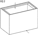
- Fig. 2 the inner receptacle 2 is positioned inside of the outer casing 1.
- the dimension of a flange 5 attached to an outer side of the inner receptacle 2 matches an internal area of the outer casing 1.
- a cavity 3 is formed and closed by the flange 5.
- Figure 3 shows a cross section of a front view of the inner receptacle 2 of the housing for an electronic component 6.
- the inner receptacle 2 forms a box having a bottom 2a and four side walls 2b, 2c, 2d, 2e.
- the inner receptacle 2 forms a chamber in which the electronic component 6 can be placed.
- the chamber is boarded by the bottom wall 2a and the side walls 2b, 2c, 2d, 2e.
- the bottom 2a and the side walls 2b, 2c, 2d, 2e are perpendicular to adjacent side walls and form a rectangular chamber.
- the side wall 2b, 2d are arranged parallel to each other and the side walls 2c, 2e are arranged parallel to each other.
- the inner receptacle 2 has a cuboid shape in the present embodiment but can have any other shapes in other embodiments. Its extents are chosen to be larger than the extents of the electronic component 6. Thereby the electronic component 6 can easily be disposed in it. It may have further retaining means inside to fix the electronic component 6.
- the flange 5 is integrally formed with the adjacent side wall and protrudes from the edge away from the opening 2f.
- the flange 5 closes the cavity 3 which is formed between the inner receptacle 2 and the outer casing 1 when the inner rreceptacle 2 and the outer casing 1 are fixed to each other.
- an adhesive can be used on the flange 5 or without the flange 5 to close and seal the cavity 3 between the outer casing 1 and the inner receptacle 2.
- the flange 5 might be attached to the outer casing 1 and protrude to the inside of the outer casing 1.
- the bottom 2a of the inner receptacle 2 is thicker than the side walls 2c, 2e for stability reason, but may have the same thickness in another embodiment. In some applications, especially if a fluid as a sealing resin 7 or an insulating oil shall be deposited in the inner receptacle 2, it is desirable to use an impermeable material for the inner receptacle 2.
- the inner receptacle 2 could be manufactured from a metal, for example, steels as carbon steel, stainless steel, alloy steel or tool steel. Other appropriate materials can be synthetic polymers such as PET, PPS, PBT, TPEs, HDPEs, PPs, PVCs or PTFEs. In case that the component is in danger of corrosion or degradation the material may be protected with a coating, a plating or another suitable treatment. Injection molding could to be a suitable manufacturing process for the production of the inner receptacle 2, but other processes might work as well.
- Fig. 4 a cross section of the side view of the inner receptacle 2 of the housing for the electronic component 6 is shown. Additionally to the features shown in Fig. 1 here three guidance rails 8 at the sidewall 2c of the inner receptacle 2 can be seen. In applications where the sealing resin 7 is used to fix an electronic component 6 in the inner receptacle 2 it can be helpful to lock electrodes attached to the electronic component 6 in place with the help of the guidance rails 8 to ensure that they protrude from the sealing resin 7 after filling and hardening of the sealing resin 7 in the inner receptacle 2.
- Fig. 5 shows a top view of the inner receptacle 2 for the housing for an electronic component 6.
- the flange 5 encircles the whole opening 2f.
- the guidance rails 8 for electrodes shown in Fig. 4 are on two side walls 2c, 2e.
- this film capacitor would be arranged here in a way where the bottom and top base are facing the side walls 2c, 2e, where the guidance rails 8 are located, and the curved surface would be parallel to the side walls 2b, 2d.
- the flange 5 on the sidewalls 2c, 2e are broader than the flange 5 on the sidewalls 2b, 2d.
- the cavity 3 has a broader extent next to the side wall 2c, 2e ,where the guidance rails 8 are located, compared to the side wall 2d, 2b.
- the damping factor in a direction perpendicular to the side walls 2c, 2e would be greater than the damping factor in a direction perpendicular to the side walls 2b, 2d.
- the flange 5, and thereby the cavity 3 may have the same extensions und the same damping factor in all directions.
- the flange 5, and thereby the cavity 3 can have different extents in every direction to customize the directional noise dampening.
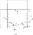
- Fig. 6 and Fig. 7 exhibits a cross section of the front and the side view of the outer casing 1.
- Fig. 8 a top view of the outer casing 1 is shown.
- the outer casing 1 forms a box having a bottom 1a and four side walls 1b, 1c, 1d, 1e.
- the outer casing 1 forms a chamber in which the inner casing 2 can be inserted.
- the chamber is boarded by the bottom 1a and the side walls 1b, 1c, 1d, 1e.
- the bottom 1a and the side walls 1b, 1c, 1d, 1e are perpendicular to adjacent side walls and form a rectangular chamber.
- At an upper side, opposite to the bottom 1a there is an opening If instead of a cover wall.
- the outer casing 1 has a cuboid shape in the present embodiment but can have any other shapes in other embodiments.
- the chamber has the same measurements as the external measurements of the flange 5 of the inner receptacle 2.
- the inner receptacle 2 with the attached flange 5 is accurately fitting into the outer casing 1.
- the cavity 3 is formed and closed by the flange 5 between the opening If and the opening 2f.
- the outer casing 1 comprises eight spacers 4.
- the width of the spacers 4 is defined as the extent perpendicular to a side wall of the outer casing 1 and the height of the spacers 4 as the extent perpendicular to the bottom 1a.
- Two long spacers 4a are positioned inside the outer casing 1 right next to side walls. The width of this long spacers 4a may have at most the width of the cavity 3. Else the inner receptacle 2 would not fit in the outer casing 1. In some distance away from the side walls 1b, 1d two short spacers 4b are arranged symmetrically.
- the height of the short spacer 4b define the width of the cavity 3 between the bottom 1a of the outer casing 1 and the bottom of the inner receptacle 2.
- the difference in height between the long spacers 4a and short spacer 4b matches the distance from the lower side of the bottom 2a to the lower side of flange 5 of the inner receptacle 2.
- Fig. 8 a top view of the outer casing 1 is shown. All of the eight spacers 4 can be seen and are arranged on top of the bottom 1a inside the outer casing 1.
- Four of the spacers 4 are long spacers 4a, which are located right in the four corners adjacent to two side walls.
- the base of this long spacers 4a is not quadratic but oblong.
- the elongated extent of the base of the long spacers 4a spaces the broader two sides of cavity 3, between the sidewalls 1c and 2c as well as between 1e and 2e.
- the shorter extent of the base of the long spacers 4a spaces the narrower two sides of the cavity 3, between the sidewalls 1b and 2b as well as between 1d and 2d.
- the other four spacers 4, which are short spacers 4b are arranged evenly in the central part of the bottom 1a area to provide a secure and even platform for the inner receptacle 2.
- the outer casing 1 can be manufactured from the same or a different material as the inner receptacle 2.
- Appropriate materials can be synthetic polymers such as PET, PPS, PBT, TPEs, HDPEs, PPs, PVCs or PTFEs.
- a potentially explosive electronic component 6, as an electrolytic capacitor is disposed in the housing, it might be safety-related required to use a flame retardant or flame resistant material for the outer casing 1.
- Flame retardant or flame resistant materials to build the outer casing 1 or inner receptacle 2 can be a metal, for example, also steels as carbon steel, stainless steel, alloy steel or tool steel.
- Other appropriate materials may be flame retardant synthetic polymers such as CR, PC, PEI, or PES.
- Injection molding could to be a suitable manufacturing process for the production of the outer casing 1, but other processes might work as well.
- Fig. 9 a schematic side view of an electronic device comprising the housing for an electronic component 6 and an electronic component 6 is shown.
- the outer casing 1 and the inner receptacle 2 are assembled and joined.
- the cavity 3 has been formed.
- an electronic component 6, for example a capacitor, is positioned and fixed by the sealing resin 7.
- An electrode of the electronic component 6 protrudes from the sealing resin 7 to allow an electrical connection to the electronic component 6.
Landscapes
- Engineering & Computer Science (AREA)
- Power Engineering (AREA)
- Microelectronics & Electronic Packaging (AREA)
- Manufacturing & Machinery (AREA)
- Casings For Electric Apparatus (AREA)
Applications Claiming Priority (1)
| Application Number | Priority Date | Filing Date | Title |
|---|---|---|---|
| DE102018119216.9A DE102018119216B4 (de) | 2018-08-07 | 2018-08-07 | Gehäuse für eine elektronische Komponente mit einem Innenbehälter und einer Außenumhüllung |
Publications (1)
| Publication Number | Publication Date |
|---|---|
| EP3608932A1 true EP3608932A1 (de) | 2020-02-12 |
Family
ID=67587409
Family Applications (1)
| Application Number | Title | Priority Date | Filing Date |
|---|---|---|---|
| EP19190577.7A Withdrawn EP3608932A1 (de) | 2018-08-07 | 2019-08-07 | Gehäuse für ein elektronisches bauteil mit einem inneren behälter und einem äusseren gehäuse |
Country Status (2)
| Country | Link |
|---|---|
| EP (1) | EP3608932A1 (de) |
| DE (1) | DE102018119216B4 (de) |
Cited By (1)
| Publication number | Priority date | Publication date | Assignee | Title |
|---|---|---|---|---|
| JP2025506529A (ja) * | 2022-02-17 | 2025-03-11 | テーデーカー エレクトロニクス アーゲー | コンデンサ、コンデンサの製造方法、およびコンデンサの使用 |
Citations (8)
| Publication number | Priority date | Publication date | Assignee | Title |
|---|---|---|---|---|
| JP3022027U (ja) * | 1995-08-25 | 1996-03-12 | ニッセイ電機株式会社 | ケース外装形電子部品 |
| DE102007054471B4 (de) * | 2007-11-13 | 2013-01-03 | Günther Spelsberg GmbH & Co. KG | Anordnung mit einer Elektroinstallationsdose und einer elektrischen und/oder elektronischen Einrichtung |
| JP2013065820A (ja) | 2011-09-01 | 2013-04-11 | Murata Mfg Co Ltd | 実装構造 |
| JP2015035505A (ja) * | 2013-08-09 | 2015-02-19 | 日立エーアイシー株式会社 | 金属化フィルムコンデンサ |
| EP3089179A1 (de) * | 2015-04-29 | 2016-11-02 | General Electric Technology GmbH | Gehäuse für elektrische anlage mit einer doppelwand zu geräuschminderungszwecken |
| CN106653361B (zh) * | 2016-11-16 | 2018-06-01 | 安徽飞达电气科技有限公司 | 一种金属化聚丙烯膜抑制电磁电源干扰用固定电容器 |
| WO2018100852A1 (ja) * | 2016-11-29 | 2018-06-07 | パナソニックIpマネジメント株式会社 | コンデンサ |
| CN108320905A (zh) * | 2017-01-17 | 2018-07-24 | 高邮欣荣电子科技有限公司 | 一种双重壳体启动电容器 |
-
2018
- 2018-08-07 DE DE102018119216.9A patent/DE102018119216B4/de active Active
-
2019
- 2019-08-07 EP EP19190577.7A patent/EP3608932A1/de not_active Withdrawn
Patent Citations (8)
| Publication number | Priority date | Publication date | Assignee | Title |
|---|---|---|---|---|
| JP3022027U (ja) * | 1995-08-25 | 1996-03-12 | ニッセイ電機株式会社 | ケース外装形電子部品 |
| DE102007054471B4 (de) * | 2007-11-13 | 2013-01-03 | Günther Spelsberg GmbH & Co. KG | Anordnung mit einer Elektroinstallationsdose und einer elektrischen und/oder elektronischen Einrichtung |
| JP2013065820A (ja) | 2011-09-01 | 2013-04-11 | Murata Mfg Co Ltd | 実装構造 |
| JP2015035505A (ja) * | 2013-08-09 | 2015-02-19 | 日立エーアイシー株式会社 | 金属化フィルムコンデンサ |
| EP3089179A1 (de) * | 2015-04-29 | 2016-11-02 | General Electric Technology GmbH | Gehäuse für elektrische anlage mit einer doppelwand zu geräuschminderungszwecken |
| CN106653361B (zh) * | 2016-11-16 | 2018-06-01 | 安徽飞达电气科技有限公司 | 一种金属化聚丙烯膜抑制电磁电源干扰用固定电容器 |
| WO2018100852A1 (ja) * | 2016-11-29 | 2018-06-07 | パナソニックIpマネジメント株式会社 | コンデンサ |
| CN108320905A (zh) * | 2017-01-17 | 2018-07-24 | 高邮欣荣电子科技有限公司 | 一种双重壳体启动电容器 |
Cited By (2)
| Publication number | Priority date | Publication date | Assignee | Title |
|---|---|---|---|---|
| JP2025506529A (ja) * | 2022-02-17 | 2025-03-11 | テーデーカー エレクトロニクス アーゲー | コンデンサ、コンデンサの製造方法、およびコンデンサの使用 |
| EP4492416A3 (de) * | 2022-02-17 | 2026-02-11 | TDK Electronics AG | Kondensator, verfahren zu seiner herstellung und seine verwendung |
Also Published As
| Publication number | Publication date |
|---|---|
| DE102018119216A1 (de) | 2020-02-13 |
| DE102018119216B4 (de) | 2020-07-23 |
Similar Documents
| Publication | Publication Date | Title |
|---|---|---|
| JPWO2014010749A1 (ja) | ケースユニット及び電子部品 | |
| EP3608932A1 (de) | Gehäuse für ein elektronisches bauteil mit einem inneren behälter und einem äusseren gehäuse | |
| CA2965216C (en) | RESONATOR AND FILTER EQUIPPED WITH A RESONATOR | |
| US11217377B2 (en) | Low inter-winding capacitance coil form | |
| JP2013078099A (ja) | 超音波センサ及びその製造方法 | |
| JP2013200426A (ja) | 吸音構造体および吸音構造体を備えた電気機器 | |
| JP7459325B2 (ja) | スピーカシステム | |
| KR100483872B1 (ko) | 압전형 전기음향 변환기 | |
| CN1791805B (zh) | 具有声音吸收装置的磁共振成像设备 | |
| KR19980032944A (ko) | 전자음향 변환기 | |
| EP1377116A2 (de) | Empfangseinheit eines Endgerätes | |
| FI114754B (fi) | Kondensaattori | |
| JP2700929B2 (ja) | 加速度センサ | |
| JP6757620B2 (ja) | 金属化フィルムコンデンサ | |
| CN111066107A (zh) | 电容器 | |
| US5184104A (en) | Electromagnetic induction apparatus with a sound suppressing arrangement | |
| JP2013254881A (ja) | 電気機器 | |
| JP2015069977A (ja) | 静止誘導電器 | |
| JP4746697B2 (ja) | 遮蔽部を備えた電子装置 | |
| TW202543301A (zh) | 揚聲器及電子設備 | |
| EP0331008B1 (de) | Elektromagnetischer Induktionsapparat mit Geräuschunterdrückungsanordung | |
| JP2001125576A (ja) | 発音体および発音体を搭載した電子機器 | |
| RU2850639C1 (ru) | Вибропреобразователь | |
| RU2850640C1 (ru) | Вибропреобразователь | |
| JP6933756B2 (ja) | 金属化フィルムコンデンサ |
Legal Events
| Date | Code | Title | Description |
|---|---|---|---|
| PUAI | Public reference made under article 153(3) epc to a published international application that has entered the european phase |
Free format text: ORIGINAL CODE: 0009012 |
|
| STAA | Information on the status of an ep patent application or granted ep patent |
Free format text: STATUS: REQUEST FOR EXAMINATION WAS MADE |
|
| 17P | Request for examination filed |
Effective date: 20190807 |
|
| AK | Designated contracting states |
Kind code of ref document: A1 Designated state(s): AL AT BE BG CH CY CZ DE DK EE ES FI FR GB GR HR HU IE IS IT LI LT LU LV MC MK MT NL NO PL PT RO RS SE SI SK SM TR |
|
| AX | Request for extension of the european patent |
Extension state: BA ME |
|
| STAA | Information on the status of an ep patent application or granted ep patent |
Free format text: STATUS: EXAMINATION IS IN PROGRESS |
|
| 17Q | First examination report despatched |
Effective date: 20210924 |
|
| RIC1 | Information provided on ipc code assigned before grant |
Ipc: H01G 2/22 20060101ALI20221201BHEP Ipc: H01G 2/10 20060101ALI20221201BHEP Ipc: H01G 4/224 20060101AFI20221201BHEP |
|
| GRAP | Despatch of communication of intention to grant a patent |
Free format text: ORIGINAL CODE: EPIDOSNIGR1 |
|
| STAA | Information on the status of an ep patent application or granted ep patent |
Free format text: STATUS: GRANT OF PATENT IS INTENDED |
|
| INTG | Intention to grant announced |
Effective date: 20230111 |
|
| STAA | Information on the status of an ep patent application or granted ep patent |
Free format text: STATUS: THE APPLICATION IS DEEMED TO BE WITHDRAWN |
|
| 18D | Application deemed to be withdrawn |
Effective date: 20230523 |