EP3608568B1 - Gegen sauerstoff, wasserstoff und wasser beständiges elektromagnetisches ventil - Google Patents
Gegen sauerstoff, wasserstoff und wasser beständiges elektromagnetisches ventil Download PDFInfo
- Publication number
- EP3608568B1 EP3608568B1 EP18781442.1A EP18781442A EP3608568B1 EP 3608568 B1 EP3608568 B1 EP 3608568B1 EP 18781442 A EP18781442 A EP 18781442A EP 3608568 B1 EP3608568 B1 EP 3608568B1
- Authority
- EP
- European Patent Office
- Prior art keywords
- valve body
- valve
- movable core
- gas
- inner diameter
- Prior art date
- Legal status (The legal status is an assumption and is not a legal conclusion. Google has not performed a legal analysis and makes no representation as to the accuracy of the status listed.)
- Active
Links
Images


Classifications
-
- F—MECHANICAL ENGINEERING; LIGHTING; HEATING; WEAPONS; BLASTING
- F16—ENGINEERING ELEMENTS AND UNITS; GENERAL MEASURES FOR PRODUCING AND MAINTAINING EFFECTIVE FUNCTIONING OF MACHINES OR INSTALLATIONS; THERMAL INSULATION IN GENERAL
- F16K—VALVES; TAPS; COCKS; ACTUATING-FLOATS; DEVICES FOR VENTING OR AERATING
- F16K31/00—Actuating devices; Operating means; Releasing devices
- F16K31/02—Actuating devices; Operating means; Releasing devices electric; magnetic
- F16K31/06—Actuating devices; Operating means; Releasing devices electric; magnetic using a magnet, e.g. diaphragm valves, cutting off by means of a liquid
-
- F—MECHANICAL ENGINEERING; LIGHTING; HEATING; WEAPONS; BLASTING
- F16—ENGINEERING ELEMENTS AND UNITS; GENERAL MEASURES FOR PRODUCING AND MAINTAINING EFFECTIVE FUNCTIONING OF MACHINES OR INSTALLATIONS; THERMAL INSULATION IN GENERAL
- F16K—VALVES; TAPS; COCKS; ACTUATING-FLOATS; DEVICES FOR VENTING OR AERATING
- F16K31/00—Actuating devices; Operating means; Releasing devices
- F16K31/02—Actuating devices; Operating means; Releasing devices electric; magnetic
- F16K31/06—Actuating devices; Operating means; Releasing devices electric; magnetic using a magnet, e.g. diaphragm valves, cutting off by means of a liquid
- F16K31/0644—One-way valve
- F16K31/0655—Lift valves
-
- F—MECHANICAL ENGINEERING; LIGHTING; HEATING; WEAPONS; BLASTING
- F16—ENGINEERING ELEMENTS AND UNITS; GENERAL MEASURES FOR PRODUCING AND MAINTAINING EFFECTIVE FUNCTIONING OF MACHINES OR INSTALLATIONS; THERMAL INSULATION IN GENERAL
- F16K—VALVES; TAPS; COCKS; ACTUATING-FLOATS; DEVICES FOR VENTING OR AERATING
- F16K31/00—Actuating devices; Operating means; Releasing devices
- F16K31/02—Actuating devices; Operating means; Releasing devices electric; magnetic
- F16K31/06—Actuating devices; Operating means; Releasing devices electric; magnetic using a magnet, e.g. diaphragm valves, cutting off by means of a liquid
- F16K31/0644—One-way valve
-
- C—CHEMISTRY; METALLURGY
- C08—ORGANIC MACROMOLECULAR COMPOUNDS; THEIR PREPARATION OR CHEMICAL WORKING-UP; COMPOSITIONS BASED THEREON
- C08L—COMPOSITIONS OF MACROMOLECULAR COMPOUNDS
- C08L27/00—Compositions of homopolymers or copolymers of compounds having one or more unsaturated aliphatic radicals, each having only one carbon-to-carbon double bond, and at least one being terminated by a halogen; Compositions of derivatives of such polymers
- C08L27/02—Compositions of homopolymers or copolymers of compounds having one or more unsaturated aliphatic radicals, each having only one carbon-to-carbon double bond, and at least one being terminated by a halogen; Compositions of derivatives of such polymers not modified by chemical after-treatment
- C08L27/12—Compositions of homopolymers or copolymers of compounds having one or more unsaturated aliphatic radicals, each having only one carbon-to-carbon double bond, and at least one being terminated by a halogen; Compositions of derivatives of such polymers not modified by chemical after-treatment containing fluorine atoms
-
- F—MECHANICAL ENGINEERING; LIGHTING; HEATING; WEAPONS; BLASTING
- F02—COMBUSTION ENGINES; HOT-GAS OR COMBUSTION-PRODUCT ENGINE PLANTS
- F02D—CONTROLLING COMBUSTION ENGINES
- F02D41/00—Electrical control of supply of combustible mixture or its constituents
- F02D41/0025—Controlling engines characterised by use of non-liquid fuels, pluralities of fuels, or non-fuel substances added to the combustible mixtures
- F02D41/0027—Controlling engines characterised by use of non-liquid fuels, pluralities of fuels, or non-fuel substances added to the combustible mixtures the fuel being gaseous
-
- F—MECHANICAL ENGINEERING; LIGHTING; HEATING; WEAPONS; BLASTING
- F16—ENGINEERING ELEMENTS AND UNITS; GENERAL MEASURES FOR PRODUCING AND MAINTAINING EFFECTIVE FUNCTIONING OF MACHINES OR INSTALLATIONS; THERMAL INSULATION IN GENERAL
- F16K—VALVES; TAPS; COCKS; ACTUATING-FLOATS; DEVICES FOR VENTING OR AERATING
- F16K1/00—Lift valves or globe valves, i.e. cut-off apparatus with closure members having at least a component of their opening and closing motion perpendicular to the closing faces
- F16K1/32—Details
- F16K1/34—Cutting-off parts, e.g. valve members, seats
- F16K1/36—Valve members
-
- F—MECHANICAL ENGINEERING; LIGHTING; HEATING; WEAPONS; BLASTING
- F16—ENGINEERING ELEMENTS AND UNITS; GENERAL MEASURES FOR PRODUCING AND MAINTAINING EFFECTIVE FUNCTIONING OF MACHINES OR INSTALLATIONS; THERMAL INSULATION IN GENERAL
- F16K—VALVES; TAPS; COCKS; ACTUATING-FLOATS; DEVICES FOR VENTING OR AERATING
- F16K1/00—Lift valves or globe valves, i.e. cut-off apparatus with closure members having at least a component of their opening and closing motion perpendicular to the closing faces
- F16K1/32—Details
- F16K1/34—Cutting-off parts, e.g. valve members, seats
- F16K1/42—Valve seats
-
- F—MECHANICAL ENGINEERING; LIGHTING; HEATING; WEAPONS; BLASTING
- F16—ENGINEERING ELEMENTS AND UNITS; GENERAL MEASURES FOR PRODUCING AND MAINTAINING EFFECTIVE FUNCTIONING OF MACHINES OR INSTALLATIONS; THERMAL INSULATION IN GENERAL
- F16K—VALVES; TAPS; COCKS; ACTUATING-FLOATS; DEVICES FOR VENTING OR AERATING
- F16K17/00—Safety valves; Equalising valves, e.g. pressure relief valves
- F16K17/02—Safety valves; Equalising valves, e.g. pressure relief valves opening on surplus pressure on one side; closing on insufficient pressure on one side
- F16K17/04—Safety valves; Equalising valves, e.g. pressure relief valves opening on surplus pressure on one side; closing on insufficient pressure on one side spring-loaded
- F16K17/0446—Safety valves; Equalising valves, e.g. pressure relief valves opening on surplus pressure on one side; closing on insufficient pressure on one side spring-loaded with an obturating member having at least a component of their opening and closing motion not perpendicular to the closing faces
- F16K17/0453—Safety valves; Equalising valves, e.g. pressure relief valves opening on surplus pressure on one side; closing on insufficient pressure on one side spring-loaded with an obturating member having at least a component of their opening and closing motion not perpendicular to the closing faces the member being a diaphragm
-
- F—MECHANICAL ENGINEERING; LIGHTING; HEATING; WEAPONS; BLASTING
- F16—ENGINEERING ELEMENTS AND UNITS; GENERAL MEASURES FOR PRODUCING AND MAINTAINING EFFECTIVE FUNCTIONING OF MACHINES OR INSTALLATIONS; THERMAL INSULATION IN GENERAL
- F16K—VALVES; TAPS; COCKS; ACTUATING-FLOATS; DEVICES FOR VENTING OR AERATING
- F16K25/00—Details relating to contact between valve members and seats
- F16K25/005—Particular materials for seats or closure elements
-
- F—MECHANICAL ENGINEERING; LIGHTING; HEATING; WEAPONS; BLASTING
- F16—ENGINEERING ELEMENTS AND UNITS; GENERAL MEASURES FOR PRODUCING AND MAINTAINING EFFECTIVE FUNCTIONING OF MACHINES OR INSTALLATIONS; THERMAL INSULATION IN GENERAL
- F16K—VALVES; TAPS; COCKS; ACTUATING-FLOATS; DEVICES FOR VENTING OR AERATING
- F16K31/00—Actuating devices; Operating means; Releasing devices
- F16K31/02—Actuating devices; Operating means; Releasing devices electric; magnetic
- F16K31/06—Actuating devices; Operating means; Releasing devices electric; magnetic using a magnet, e.g. diaphragm valves, cutting off by means of a liquid
- F16K31/0644—One-way valve
- F16K31/0672—One-way valve the valve member being a diaphragm
-
- H—ELECTRICITY
- H01—ELECTRIC ELEMENTS
- H01M—PROCESSES OR MEANS, e.g. BATTERIES, FOR THE DIRECT CONVERSION OF CHEMICAL ENERGY INTO ELECTRICAL ENERGY
- H01M8/00—Fuel cells; Manufacture thereof
- H01M8/04—Auxiliary arrangements, e.g. for control of pressure or for circulation of fluids
-
- H—ELECTRICITY
- H01—ELECTRIC ELEMENTS
- H01M—PROCESSES OR MEANS, e.g. BATTERIES, FOR THE DIRECT CONVERSION OF CHEMICAL ENERGY INTO ELECTRICAL ENERGY
- H01M8/00—Fuel cells; Manufacture thereof
- H01M8/04—Auxiliary arrangements, e.g. for control of pressure or for circulation of fluids
- H01M8/04082—Arrangements for control of reactant parameters, e.g. pressure or concentration
- H01M8/04089—Arrangements for control of reactant parameters, e.g. pressure or concentration of gaseous reactants
- H01M8/04097—Arrangements for control of reactant parameters, e.g. pressure or concentration of gaseous reactants with recycling of the reactants
-
- F—MECHANICAL ENGINEERING; LIGHTING; HEATING; WEAPONS; BLASTING
- F02—COMBUSTION ENGINES; HOT-GAS OR COMBUSTION-PRODUCT ENGINE PLANTS
- F02M—SUPPLYING COMBUSTION ENGINES IN GENERAL WITH COMBUSTIBLE MIXTURES OR CONSTITUENTS THEREOF
- F02M2200/00—Details of fuel-injection apparatus, not otherwise provided for
- F02M2200/90—Selection of particular materials
- F02M2200/9015—Elastomeric or plastic materials
-
- F—MECHANICAL ENGINEERING; LIGHTING; HEATING; WEAPONS; BLASTING
- F02—COMBUSTION ENGINES; HOT-GAS OR COMBUSTION-PRODUCT ENGINE PLANTS
- F02M—SUPPLYING COMBUSTION ENGINES IN GENERAL WITH COMBUSTIBLE MIXTURES OR CONSTITUENTS THEREOF
- F02M63/00—Other fuel-injection apparatus having pertinent characteristics not provided for in groups F02M39/00 - F02M57/00 or F02M67/00; Details, component parts, or accessories of fuel-injection apparatus, not provided for in, or of interest apart from, the apparatus of groups F02M39/00 - F02M61/00 or F02M67/00; Combination of fuel pump with other devices, e.g. lubricating oil pump
- F02M63/0012—Valves
- F02M63/0014—Valves characterised by the valve actuating means
- F02M63/0015—Valves characterised by the valve actuating means electrical, e.g. using solenoid
- F02M63/0017—Valves characterised by the valve actuating means electrical, e.g. using solenoid using electromagnetic operating means
-
- H—ELECTRICITY
- H01—ELECTRIC ELEMENTS
- H01M—PROCESSES OR MEANS, e.g. BATTERIES, FOR THE DIRECT CONVERSION OF CHEMICAL ENERGY INTO ELECTRICAL ENERGY
- H01M8/00—Fuel cells; Manufacture thereof
- H01M8/04—Auxiliary arrangements, e.g. for control of pressure or for circulation of fluids
- H01M8/04082—Arrangements for control of reactant parameters, e.g. pressure or concentration
- H01M8/04089—Arrangements for control of reactant parameters, e.g. pressure or concentration of gaseous reactants
-
- Y—GENERAL TAGGING OF NEW TECHNOLOGICAL DEVELOPMENTS; GENERAL TAGGING OF CROSS-SECTIONAL TECHNOLOGIES SPANNING OVER SEVERAL SECTIONS OF THE IPC; TECHNICAL SUBJECTS COVERED BY FORMER USPC CROSS-REFERENCE ART COLLECTIONS [XRACs] AND DIGESTS
- Y02—TECHNOLOGIES OR APPLICATIONS FOR MITIGATION OR ADAPTATION AGAINST CLIMATE CHANGE
- Y02E—REDUCTION OF GREENHOUSE GAS [GHG] EMISSIONS, RELATED TO ENERGY GENERATION, TRANSMISSION OR DISTRIBUTION
- Y02E60/00—Enabling technologies; Technologies with a potential or indirect contribution to GHG emissions mitigation
- Y02E60/30—Hydrogen technology
- Y02E60/50—Fuel cells
Definitions
- the present invention relates to an electromagnetic valve having durability against oxygen, hydrogen and water flowing in a flow path.
- an electromagnetic valve for a fuel cell must have durability against oxygen, hydrogen and water flowing in a flow path.
- JP-A-2006-153223 has proposed that a valve body is made of aluminum.
- a diaphragm type of structure disclosed in JP-A-2002-195428 (a peripheral portion of a valve body is a diaphragm part) is also known.
- JP-A-2006-153223 and JP-A-2002-195428 are raised as prior art documents.
- An electromagnetic valve having a similar architecture is described in US 2007/0241298 A1 .
- the present invention is an electromagnetic valve including: a fixed core; a movable core capable of approaching the fixed core when subjected to an action of an electromagnetic force; a valve body provided at an end of the movable core away from the fixed core; a tubular part fixed relative to the fixed core and configured to guide movement of the movable core; a gas flow path forming member connected to a side of the tubular part away from the fixed core, having an annularly protruding valve seat on which the valve body can be seated; an elastic body capable of urging the movable core in a direction of moving the movable core away from the fixed core and allowing the valve body to be seated on the valve seat; and an electromagnetic coil part capable of applying an electromagnetic force to the movable core to move the movable core toward the fixed core against the urging force of the elastic body and allowing the valve body to be released from the valve seat; wherein the tubular part and/or the gas flow path forming member has an annular gas accumulating space around the valve body of the movable
- a hardness of the valve body measured by a durometer type A defined by JIS K 6253 has been adjusted to 60 to 70. In this case, the durability is further improved.
- valve body is made of 5 to 30 parts of MT carbon black added to and blended with 100 parts of the ternary fluororubber of vinylidene fluoride / tetrafluoroethylene / hexafluoropropylene copolymer. In this case, the durability is further improved.
- a hardness of the valve body measured by a durometer type A defined by JIS K 6253 has been adjusted to 60 to 70. In this case, the durability is further improved.
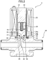
- Fig. 1 is a schematic cross-sectional view of a valve closed state of an electromagnetic valve according to a first embodiment of the present invention
- Fig. 2 is a schematic cross-sectional view of a valve opened state of an electromagnetic valve according to the first embodiment of the present invention.
- an electromagnetic valve 1 includes: a fixed core 10; and a movable core 20 that can approach the fixed core 10 when subjected to an action of an electromagnetic force.
- a valve body 25 is attached to an end of the movable core 20 away from the fixed core 10.
- a hardness measured by a durometer type A defined by JIS K 6253 is 69, a tensile strength is 22.7 MPa, and an elongation at break is 375 %.
- the hardness of the valve body 25 measured by a durometer type A defined by JIS K 6253 is within the range of 50 to 90, more preferably 60 to 70, that the tensile strength of the valve body 25 is within the range of 10 to 35 MPa, and that the elongation at break of the valve body 25 is within the range of 100 to 500 %;
- tubular part 31 and the gas flow path forming member 30 are connected via two spacer members 36a, 36b, a ring core member 37, a ring member 38 and an O-ring 39.
- spacer members 36a, 36b a ring core member 37
- ring member 38 a ring member 38
- O-ring 39 a concrete connecting manner for both of them is not limited particularly.
- a gas introduction hole 32 (gas introduction passage), whose cross section is circular, is provided in an inner region of the valve seat 33.
- the valve body 25 In a normal state, the valve body 25 is seated on the valve seat 33 so that the gas introduction hole 32 is closed.
- a supply mechanism for supplying hydrogen, oxygen, and water to the gas introduction hole 32 in an arbitrary order is connected to the gas introduction hole 32 of the present embodiment.
- a gas discharge hole 35 (gas discharge passage) is provided in an outer region of the valve seat 33.
- a spring 15 is provided between the fixed core 10 and the movable core 20, the spring 15 being capable of urging the movable core 20 in a direction of moving the movable core 20 away from the fixed core 10 and allowing the valve body 25 to be seated on the valve seat 33.
- the spring 15 may be replaced with another kind of elastic body that achieves the same function.
- an electromagnetic coil part 23 which is capable of applying an electromagnetic force to the movable core 20 to move the movable core 20 toward (closer to) the fixed core 10 against the urging force of the spring 15 and allowing the valve body 25 to be released from the valve seat 33 (gas introduction hole 32).
- the electromagnetic coil part 23 is connected to a control unit (not shown) via electric wires.
- the gas accumulating space 34 and the gas discharge hole 35 maintain their communication state regardless of how relative positions of the fixed core 10 and the movable core 20 are (regardless of how a compressed/extended state of the spring 15 is).
- the inner diameter of the gas introduction hole 32 is 2.3 mm. However, it can be selected from a range of about 2.0 to 4.0 mm, for example.
- dimensions (sizes) of the respective members have been adjusted by using the inner diameter of the gas introduction hole 32 as a standard.
- the diameter of the valve body 25 has been adjusted to be 2.0 times the inner diameter of the gas introduction hole 32 (selectable from a range of 1.5 times to 3.0 times the inner diameter of the gas introduction hole 32)
- the thickness of the valve of the valve body 25 has been adjusted to be 0.7 times the inner diameter of the gas introduction hole 32 (selectable from a range of 0.3 times or more the inner diameter of the gas introduction hole 32)
- the protruding height of the valve seat 33 has been adjusted to be 0.7 times the inner diameter of the gas introduction hole 32 (selectable from a range of 0.3 times or more the inner diameter of the gas introduction hole 32)
- the inner diameter of the annular gas accumulating space 34 has been adjusted to be 4.0 times the inner diameter of the gas introduction hole 32 (selectable from a range of 2.0 times to 5.0 times the inner diameter of the gas introduction hole 32).
- a distance in which the movable core 20 is moved by the electromagnetic coil part 23 has been adjusted to be 0.2 times the inner diameter of the gas introduction hole 32 (selectable from a range of 0.1 times to 0.3 times the inner diameter of the gas introduction hole 32).
- the movable core 20 In a normal state, the movable core 20 is biased in a direction of moving the movable core 20 away from the fixed core 10 by the urging force of the spring 15 provided between the fixed core 10 and the movable core 20, and thus the valve body 25 is seated on the valve seat 33 and the gas introduction hole 32 is closed.
- the electromagnetic coil part 23 When a valve opening command is inputted, the electromagnetic coil part 23 is activated via the control unit (not shown). Thus, the electromagnetic coil part 23 applies an electromagnetic force to the movable core 20, and moves the movable core 20 toward (closer to) the fixed core 10 against the urging force of the spring 15. As a result, the valve body 25 is released from the gas introduction hole 32, and the electromagnetic valve 1 is opened.
- valve opening command When a valve opening command is inputted, the electromagnetic coil part 23 is activated and the valve body 25 is released (moved away) from valve seat 33, so that the gas (hydrogen and/or oxygen) and/or water that has been supplied into the gas introduction hole 32 flows into the gas discharge hole 35 through the gas accumulating space 34.
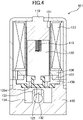
- Fig. 3 is a schematic cross-sectional view of a valve closed state of an electromagnetic valve according to a second embodiment of the present invention
- Fig. 4 is a schematic cross-sectional view of a valve opened state of an electromagnetic valve according to the second embodiment of the present invention.
- an electromagnetic valve 101 includes: a fixed core 110; and a movable core 120 that can approach the fixed core 110 when subjected to an action of an electromagnetic force.
- a valve body 125 is attached to an end of the movable core 120 away from the fixed core 110.
- the main component of the valve body 125 of the second embodiment is also a ternary fluororubber consisting of vinylidene fluoride / tetrafluoroethylene / hexafluoropropylene copolymer (specifically, the trade name "DAI-EL G-902"). 5 to 30 parts of MT carbon black has been additively blended with 100 parts of the ternary fluororubber, followed by a vulcanization treatment.
- a hardness measured by a durometer type A defined by JIS K 6253 is 69, a tensile strength is 22.7 MPa, and an elongation at break is 375 %.
- the hardness of the valve body 125 measured by a durometer type A defined by JIS K 6253 is within the range of 50 to 90, more preferably 60 to 70, that the tensile strength of the valve body 125 is within the range of 10 to 35 MPa, and that the elongation at break of the valve body 125 is within the range of 100 to 500 %. (These characteristic values do not substantially differ between a state before the valve body 125 has been molded (material state) and a state after the valve body 125 has been molded.)
- a diaphragm part 125d is provided at an outer peripheral portion thereof.
- a peripheral portion of the diaphragm part 125d is fixed to a gas flow path forming member 130 and a ring member 138, which will be described later.
- a tubular part 131 configured to guide movement of the movable core 120 is fixed relative to the fixed core 110.
- a gas flow path forming member 130 is connected to a side of the tubular part 131 away from the fixed core 110, the gas flow path forming member 130 having an annularly valve seat 133 on which the valve body 125 can be seated.
- the valve seat 133 is made of stainless steel and protrudes from an outer region with respect to the valve seat 133 toward the fixed core 110.
- tubular part 131 and the gas flow path forming member 130 are connected via a spacer member 136, a ring core member 137 and a ring member 138.
- a concrete connecting manner for both of them is not limited particularly.
- a gas introduction hole 132 (gas introduction passage), whose cross section is circular, is provided in an inner region of the valve seat 133.
- the valve body 125 In a normal state, the valve body 125 is seated on the valve seat 133 so that the gas introduction hole 132 is closed.
- a supply mechanism for supplying hydrogen, oxygen, and water to the gas introduction hole 132 in an arbitrary order is connected to the gas introduction hole 132 of the present embodiment.
- a gas discharge hole 135 gas discharge passage is provided in an outer region of the valve seat 133.
- a spring 115 is provided between the fixed core 110 and the movable core 120, the spring 115 being capable of urging the movable core 120 in a direction of moving the movable core 120 away from the fixed core 110 and allowing the valve body 125 to be seated on the valve seat 133.
- the spring 115 may be replaced with another kind of elastic body that achieves the same function.
- an electromagnetic coil part 123 which is capable of applying an electromagnetic force to the movable core 120 to move the movable core 120 toward (closer to) the fixed core 110 against the urging force of the spring 15 and allowing the valve body 125 to be released from the valve seat 133 (gas introduction hole 132).
- the electromagnetic coil part 123 is connected to a control unit (not shown) via electric wires.
- the tubular part 131 and the gas flow path forming member 130 has an annular gas accumulating space 134 around the valve seat 133.
- the gas accumulating space 134 has a cylindrical shape which is rotationally symmetric with respect to an axis of the valve seat 133. As shown in Figs. 3 and 4 , an end surface of the gas accumulating space 134 away from the fixed core 110 is flat except for the valve seat 133 and defines a protruding height of the valve seat 133.
- the gas accumulating space 134 and the gas discharge hole 135 maintain their communication state regardless of how relative positions of the fixed core 110 and the movable core 120 are (regardless of how a compressed/extended state of the spring 115 is).
- the inner diameter of the gas introduction hole 132 is 2.3 mm. However, it can be selected from a range of about 2.0 to 4.0 mm, for example.
- dimensions (sizes) of the respective members have been adjusted by using the inner diameter of the gas introduction hole 132 as a standard.
- the diameter of an inner region of the valve body 125 with respect to the diaphragm part 125d has been adjusted to be 2.0 times the inner diameter of the gas introduction hole 32 (selectable from a range of 1.5 times to 3.0 times the inner diameter of the gas introduction hole 32)
- the thickness of the inner region of the valve body 125 with respect to the diaphragm part 125d has been adjusted to be 0.7 times the inner diameter of the gas introduction hole 132 (selectable from a range of 0.3 times or more the inner diameter of the gas introduction hole 132)
- the protruding height of the valve seat 133 has been adjusted to be 2.0 times the inner diameter of the gas introduction hole 132 (selectable from a range of 0.3 times or more the inner diameter of the gas introduction hole 132)
- the inner diameter of the annular gas accumulating space 134 has been adjusted to be 4.0
- a distance in which the movable core 120 is moved by the electromagnetic coil part 123 has been adjusted to be 0.2 times the inner diameter of the gas introduction hole 132 (selectable from a range of 0.1 times to 0.3 times the inner diameter of the gas introduction hole 132).
- the movable core 120 is biased in a direction of moving the movable core 120 away from the fixed core 110 by the urging force of the spring 115 provided between the fixed core 110 and the movable core 120, and thus the valve body 125 is seated on the valve seat 133 and the gas introduction hole 132 is closed.
- the electromagnetic coil part 123 When a valve opening command is inputted, the electromagnetic coil part 123 is activated via the control unit (not shown). Thus, the electromagnetic coil part 123 applies an electromagnetic force to the movable core 120, and moves the movable core 120 toward (closer to) the fixed core 110 against the urging force of the spring 115. As a result, the diaphragm part 125d of the valve body 125 is deformed such that the valve body 125 is released from the gas introduction hole 132 and the electromagnetic valve 101 is opened.
- valve opening command When a valve opening command is inputted, the electromagnetic coil part 123 is activated and the valve body 125 is released (moved away) from valve seat 133, so that the gas (hydrogen and/or oxygen) and/or water that has been supplied into the gas introduction hole 132 flows into the gas discharge hole 135 through the gas accumulating space 134.
Landscapes
- Engineering & Computer Science (AREA)
- General Engineering & Computer Science (AREA)
- Mechanical Engineering (AREA)
- Chemical & Material Sciences (AREA)
- Life Sciences & Earth Sciences (AREA)
- Chemical Kinetics & Catalysis (AREA)
- Sustainable Development (AREA)
- Sustainable Energy (AREA)
- Electrochemistry (AREA)
- General Chemical & Material Sciences (AREA)
- Manufacturing & Machinery (AREA)
- Combustion & Propulsion (AREA)
- Electromagnetism (AREA)
- Physics & Mathematics (AREA)
- Health & Medical Sciences (AREA)
- Medicinal Chemistry (AREA)
- Polymers & Plastics (AREA)
- Organic Chemistry (AREA)
- Magnetically Actuated Valves (AREA)
- Fuel Cell (AREA)
Claims (8)
- Elektromagnetisches Ventil (1; 101), umfassendeinen festen Kern (10; 110),einen beweglichen Kern (20; 120), der sich dem festen Kern (10; 110) nähern kann, wenn er einer elektromagnetischen Kraft ausgesetzt ist,einen Ventilkörper (25; 125), der an einem vom festen Kern (10; 110) entfernten Ende des beweglichen Kerns (20; 120) vorgesehen ist,ein röhrenförmiges Teil (31; 131), das relativ zu dem festen Kern (10; 110) befestigt und so ausgelegt ist, dass es die Bewegung des beweglichen Kerns (20; 120) lenkt,ein Element, das einen Gasströmungsweg bildet und mit einer vom festen Kern (10; 110) abgewandten Seite des rohrförmigen Teils (31; 131) verbunden ist und einen ringförmig vorstehenden Ventilsitz (33; 133) aufweist, auf den der Ventilkörper (25; 125) aufgesetzt werden kann, einen elastischen Körper, der in der Lage ist, den beweglichen Kern (20; 120) in eine Richtung zu drücken, in der der bewegliche Kern (20; 120) von dem festen Kern (10; 110) weg bewegt wird, und der es dem Ventilkörper (25; 125) ermöglicht, auf dem Ventilsitz (33; 133) zu sitzen, undein elektromagnetisches Spulenteil (23; 123), das in der Lage ist, eine elektromagnetische Kraft auf den beweglichen Kern (20; 120) auszuüben, um den beweglichen Kern (20; 120) gegen die Druckkraft des elastischen Körpers in Richtung des festen Kerns (10; 110) zu bewegen und es dem Ventilkörper (25; 125) zu ermöglichen, vom Ventilsitz (33; 133) gelöst zu werden,wobeider rohrförmige Teil (31; 131) und/oder das den Gasströmungsweg bildende Element einen ringförmigen Gassammelraum um den Ventilkörper (25; 125) des beweglichen Kerns (20; 120) aufweist,das den Gasströmungsweg bildende Element einen Gaseinleitungsdurchlass in einem inneren Bereich des Ventilsitzes (33; 133) aufweist,das den Gasströmungsweg bildende Element einen Gasauslasskanal in einem äußeren Bereich des Ventilsitzes (33; 133) aufweist,der ringförmige Gassammelraum und der Gasauslasskanal ihren Verbindungszustand unabhängig davon beibehalten, wie die relativen Positionen des festen Kerns (10; 110) und des beweglichen Kerns (20; 120) sind,der Ventilkörper (25; 125) einen ternären Fluorkautschuk aus Vinylidenfluorid/Tetrafluorethylen/Hexafluorpropylen-Copolymer als Hauptbestandteil hat,eine Härte des Ventilkörpers (25; 125), gemessen mit einem Durometer Typ A nach JIS K 6253, auf 50 bis 90 eingestellt wurde,eine Zugfestigkeit des Ventilkörpers (25; 125) auf 10 bis 35 MPa eingestellt wurde,eine Bruchdehnung des Ventilkörpers (25; 125) auf 100 bis 500 % eingestellt wurde, der Ventilsitz (33; 133) aus rostfreiem Stahl hergestellt ist, wobeiein Abstand, in dem der bewegliche Kern (20; 120) durch den elektromagnetischen Spulenteil (23; 123) bewegbar ist, innerhalb eines Bereichs des 0,1- bis 0,3-fachen eines Innendurchmessers des Gasaustrittskanals liegt,der Durchmesser des Ventilkörpers (25; 125) im Bereich des 1,5- bis 3,0-fachen des Innendurchmessers des Gasaustrittskanals liegt,eine Dicke des Ventilkörpers (25; 125) das 0,3-fache des Innendurchmessers des Gasaustrittskanals oder mehr beträgt,eine vorspringende Höhe des Ventilsitzes (33; 133) das 0,3-fache des Innendurchmessers des Gasaustrittskanals oder mehr beträgt, undein Innendurchmesser des ringförmigen Gassammelraums im Bereich des 2,0- bis 5,0-fachen des Innendurchmessers des Gasaustrittskanals liegt.
- Elektromagnetisches Ventil (1; 101) nach Anspruch 1, wobei
der Ventilkörper (25; 125) aus 5 bis 30 Teilen MT-Ruß besteht, der mit 100 Teilen des ternären Fluorkautschuks aus Vinylidenfluorid/Tetrafluorethylen/Hexafluorpropylen-Copolymer vermischt ist. - Elektromagnetisches Ventil (1; 101) nach Anspruch 1 oder 2, wobei eine Härte des Ventilkörpers (25; 125), gemessen mit einem Durometer Typ A, definiert durch JIS K 6253, auf 60 bis 70 eingestellt ist.
- Elektromagnetisches Ventil (1; 101) nach einem der Ansprüche 1 bis 3, mit einer Versorgungsvorrichtung zur Versorgung mit Wasserstoff, Sauerstoff und Wasser, wobei die Versorgungsvorrichtung mit dem Gaseinleitungsdurchlass verbunden ist.
- Elektromagnetisches Ventil (1; 101), umfassendeinen festen Kern (10; 110),einen beweglichen Kern (20; 120), der sich dem festen Kern (10; 110) nähern kann, wenn er einer elektromagnetischen Kraft ausgesetzt ist,einen Ventilkörper (25; 125), der an einem vom festen Kern (10; 110) entfernten Ende des beweglichen Kerns (20; 120) vorgesehen ist,ein röhrenförmiges Teil (31; 131), das relativ zu dem festen Kern (10; 110) befestigt und so ausgelegt ist, dass es die Bewegung des beweglichen Kerns (20; 120) lenkt,ein Element, das einen Gasströmungsweg bildet und das mit einer vom festen Kern (10; 110) abgewandten Seite des rohrförmigen Teils (31; 131) verbunden ist und einen ringförmig vorstehenden Ventilsitz (33; 133) aufweist, auf den der Ventilkörper (25; 125) aufgesetzt werden kann, einen elastischen Körper, der in der Lage ist, den beweglichen Kern (20; 120) in eine Richtung zu drücken, in der der bewegliche Kern (20; 120) von dem festen Kern (10; 110) weg bewegt wird, und der es dem Ventilkörper (25; 125) ermöglicht, auf dem Ventilsitz (33; 133) zu sitzen, undein elektromagnetisches Spulenteil (23;123), das in der Lage ist, eine elektromagnetische Kraft auf den beweglichen Kern (20; 120) auszuüben, um den beweglichen Kern (20; 120) gegen die Druckkraft des elastischen Körpers in Richtung des festen Kerns (10; 110) zu bewegen und zu ermöglichen, dass der Ventilkörper (25; 125) vom Ventilsitz (33; 133) gelöst wird,wobeiein peripherer Abschnitt eines Membranteils (125d; 130), der um den Ventilkörper (25; 125) herum vorgesehen ist, an dem rohrförmigen Teil (31; 131) und/oder an dem Element, das den Gasströmungsweg bildet, befestigt ist,der rohrförmige Teil (31; 131) und/oder das den Gasströmungsweg bildende Element einen ringförmigen Gassammelraum um den ringförmig vorstehenden Ventilsitz (33; 133) aufweist, das den Gasströmungsweg bildende Element einen Gaseinleitungsdurchlass in einem inneren Bereich des Ventilsitzes (33; 133) aufweist,das den Gasströmungsweg bildende Element einen Gasauslasskanal in einem äußeren Bereich des Ventilsitzes (33; 133) aufweist,der ringförmige Gassammelraum und der Gasauslasskanal ihren Verbindungszustand unabhängig davon beibehalten, wie die relativen Positionen des festen Kerns (10; 110) und des beweglichen Kerns (20; 120) sind,der Ventilkörper (25; 125) einen ternären Fluorkautschuk aus Vinylidenfluorid/Tetrafluorethylen/Hexafluorpropylen-Copolymer als Hauptbestandteil hat,eine Härte des Ventilkörpers (25; 125), gemessen mit einem Durometer Typ A nach JIS K 6253, auf 50 bis 90 eingestellt wurde,eine Zugfestigkeit des Ventilkörpers (25; 125) auf 10 bis 35 MPa eingestellt wurde,eine Bruchdehnung des Ventilkörpers (25; 125) auf 100 bis 500 % eingestellt wurde,der Ventilsitz (33; 133) aus rostfreiem Stahl hergestellt ist,ein Abstand, in dem der bewegliche Kern (20; 120) durch den elektromagnetischen Spulenteil (23; 123) bewegbar ist, innerhalb eines Bereichs des 0,1- bis 0,3-fachen eines Innendurchmessers des Gasaustrittskanals liegt,ein Durchmesser eines inneren Bereichs des Ventilkörpers (25; 125) in Bezug auf den Membranteil (125d; 130) innerhalb eines Bereichs vom 1,5- bis 3,0-fachen des Innendurchmessers des Gasauslasskanals liegt,eine Dicke des inneren Bereichs des Ventilkörpers (25; 125) in Bezug auf den Membranteil (125d; 130) das 0,3-fache des Innendurchmessers des Gasauslasskanals oder mehr beträgt, eine vorspringende Höhe des Ventilsitzes (33; 133) das 0,3-fache des Innendurchmessers des Gasaustrittskanals oder mehr beträgt, undein Innendurchmesser des ringförmigen Gassammelraums im Bereich des 2,0- bis 5,0-fachen des Innendurchmessers des Gasaustrittskanals liegt.
- Elektromagnetisches Ventil (1; 101) nach Anspruch 5, wobei
der Ventilkörper (25; 125) aus 5 bis 30 Teilen MT-Ruß besteht, der mit 100 Teilen des ternären Fluorkautschuks aus Vinylidenfluorid/Tetrafluorethylen/Hexafluorpropylen-Copolymer vermischt ist. - Elektromagnetisches Ventil (1; 101) nach Anspruch 5 oder 6, wobei
eine Härte des Ventilkörpers (25; 125), gemessen mit einem Durometer Typ A nach JIS K 6253, auf 60 bis 70 eingestellt wurde. - Elektromagnetisches Ventil (1; 101) nach einem der Ansprüche 5 bis 7,
mit einem Versorgungsmechanismus für die Zufuhr von Wasserstoff, Sauerstoff und Wasser, der an den Gaseinleitungsdurchlass angeschlossen ist.
Applications Claiming Priority (2)
| Application Number | Priority Date | Filing Date | Title |
|---|---|---|---|
| JP2017073850A JP6153684B1 (ja) | 2017-04-03 | 2017-04-03 | 酸素、水素及び水に対する耐久性を有する電磁弁 |
| PCT/JP2018/014261 WO2018186393A1 (ja) | 2017-04-03 | 2018-04-03 | 酸素、水素及び水に対する耐久性を有する電磁弁 |
Publications (3)
| Publication Number | Publication Date |
|---|---|
| EP3608568A1 EP3608568A1 (de) | 2020-02-12 |
| EP3608568A4 EP3608568A4 (de) | 2020-12-30 |
| EP3608568B1 true EP3608568B1 (de) | 2023-01-25 |
Family
ID=59218482
Family Applications (1)
| Application Number | Title | Priority Date | Filing Date |
|---|---|---|---|
| EP18781442.1A Active EP3608568B1 (de) | 2017-04-03 | 2018-04-03 | Gegen sauerstoff, wasserstoff und wasser beständiges elektromagnetisches ventil |
Country Status (7)
| Country | Link |
|---|---|
| US (1) | US11098816B2 (de) |
| EP (1) | EP3608568B1 (de) |
| JP (1) | JP6153684B1 (de) |
| KR (1) | KR102414475B1 (de) |
| CN (1) | CN110475996B (de) |
| TW (1) | TWI665402B (de) |
| WO (1) | WO2018186393A1 (de) |
Cited By (1)
| Publication number | Priority date | Publication date | Assignee | Title |
|---|---|---|---|---|
| DE102023003450A1 (de) | 2023-08-23 | 2025-02-27 | Staiger Gmbh & Co. Kg | Ventil |
Families Citing this family (6)
| Publication number | Priority date | Publication date | Assignee | Title |
|---|---|---|---|---|
| EP3879205A4 (de) * | 2018-11-07 | 2022-08-03 | Shinwa Controls Co., Ltd. | Temperaturanpassungssystem |
| JP7447414B2 (ja) | 2019-09-26 | 2024-03-12 | ニデックパワートレインシステムズ株式会社 | 電磁弁 |
| DE102019215285A1 (de) * | 2019-10-04 | 2021-04-08 | Robert Bosch Gmbh | Brennstoffzellenschließsystem |
| KR20220113368A (ko) * | 2019-12-18 | 2022-08-12 | 신와 콘트롤즈 가부시키가이샤 | 다이어프램 부재를 다이어프램 보스에 부착하는 방법 및 다이어프램 부재를 다이어프램 보스에 부착하는 로봇팔 장치 |
| JP7655884B2 (ja) * | 2022-05-24 | 2025-04-02 | Ckd株式会社 | 流体制御弁およびその製造方法 |
| EP4299958A1 (de) * | 2022-06-13 | 2024-01-03 | Innovatherm Prof. Dr. Leisenberg GmbH & Co. KG | Ventil und verfahren zum betrieb |
Family Cites Families (16)
| Publication number | Priority date | Publication date | Assignee | Title |
|---|---|---|---|---|
| US5269539A (en) * | 1992-04-13 | 1993-12-14 | Trw Inc. | Hydraulic shaft seal |
| CN1085297A (zh) * | 1993-08-26 | 1994-04-13 | 梧州市火柴厂 | 自保持微功耗膜片式直流电磁阀 |
| TW479773U (en) | 1996-12-01 | 2002-03-11 | Tadahiro Ohmi | Fluid control valve and fluid supply/exhaust system |
| US20070241298A1 (en) * | 2000-02-29 | 2007-10-18 | Kay Herbert | Electromagnetic apparatus and method for controlling fluid flow |
| US6409147B1 (en) * | 2000-06-13 | 2002-06-25 | Thomas M. Kenny | Thermally operated valve for automatically modulating the flow of fluids |
| JP3657878B2 (ja) | 2000-12-27 | 2005-06-08 | 伸和コントロールズ株式会社 | ダイヤフラム型電磁弁 |
| JP2006153223A (ja) | 2004-11-30 | 2006-06-15 | Keihin Corp | 燃料電池用集積型弁装置 |
| JP4754339B2 (ja) | 2005-12-02 | 2011-08-24 | 三星エスディアイ株式会社 | 燃料電池用の封止材、燃料電池及び燃料電池の製造方法 |
| JP5239857B2 (ja) * | 2006-06-23 | 2013-07-17 | ダイキン工業株式会社 | パーオキサイド架橋用フッ素ゴム組成物およびゴム積層体の製造方法 |
| FR2922984B1 (fr) * | 2007-10-31 | 2013-09-27 | Saint Gobain Performance Plast | Vanne ayant un joint rigide |
| IT1395777B1 (it) * | 2009-09-09 | 2012-10-19 | Elbi Int Spa | Gruppo elettrovalvolare per il controllo del flusso di un fluido, particolarmente per macchine lavatrici |
| KR101537179B1 (ko) * | 2011-01-05 | 2015-07-15 | 다이킨 고교 가부시키가이샤 | 불소 고무 성형품 |
| JP2013082888A (ja) * | 2011-09-30 | 2013-05-09 | Daikin Industries Ltd | 架橋性フッ素ゴム組成物、フッ素ゴム成形品及びその製造方法 |
| FR3000533B1 (fr) * | 2012-12-28 | 2016-05-27 | Saint-Gobain Performance Plastics France | Joint d'etancheite pour une vanne et vanne incorporant un tel joint |
| JP5892276B1 (ja) * | 2014-03-05 | 2016-03-23 | ダイキン工業株式会社 | フッ素ゴム組成物及びフッ素ゴム成形品 |
| EP3263869B1 (de) * | 2016-06-30 | 2023-05-03 | Hamilton Sundstrand Corporation | Dosierventil |
-
2017
- 2017-04-03 JP JP2017073850A patent/JP6153684B1/ja not_active Expired - Fee Related
- 2017-12-28 TW TW106146165A patent/TWI665402B/zh not_active IP Right Cessation
-
2018
- 2018-04-03 WO PCT/JP2018/014261 patent/WO2018186393A1/ja not_active Ceased
- 2018-04-03 EP EP18781442.1A patent/EP3608568B1/de active Active
- 2018-04-03 CN CN201880022173.XA patent/CN110475996B/zh not_active Expired - Fee Related
- 2018-04-03 KR KR1020197031097A patent/KR102414475B1/ko not_active Expired - Fee Related
- 2018-04-03 US US16/488,650 patent/US11098816B2/en not_active Expired - Fee Related
Cited By (1)
| Publication number | Priority date | Publication date | Assignee | Title |
|---|---|---|---|---|
| DE102023003450A1 (de) | 2023-08-23 | 2025-02-27 | Staiger Gmbh & Co. Kg | Ventil |
Also Published As
| Publication number | Publication date |
|---|---|
| CN110475996B (zh) | 2021-06-15 |
| CN110475996A (zh) | 2019-11-19 |
| JP2018179019A (ja) | 2018-11-15 |
| EP3608568A4 (de) | 2020-12-30 |
| JP6153684B1 (ja) | 2017-06-28 |
| TWI665402B (zh) | 2019-07-11 |
| TW201837355A (zh) | 2018-10-16 |
| EP3608568A1 (de) | 2020-02-12 |
| US11098816B2 (en) | 2021-08-24 |
| KR102414475B1 (ko) | 2022-06-28 |
| WO2018186393A1 (ja) | 2018-10-11 |
| KR20190132439A (ko) | 2019-11-27 |
| US20190376611A1 (en) | 2019-12-12 |
Similar Documents
| Publication | Publication Date | Title |
|---|---|---|
| EP3608568B1 (de) | Gegen sauerstoff, wasserstoff und wasser beständiges elektromagnetisches ventil | |
| EP2072871A2 (de) | Rückschlagventil | |
| JP5593470B2 (ja) | チェックバルブ | |
| JP5636301B2 (ja) | 弁座体および弁装置 | |
| US9194501B2 (en) | Pressure balanced spring loaded overtravel sealing apparatus | |
| EP3454161B1 (de) | Druckminderungsventil | |
| KR102107330B1 (ko) | 전자 밸브 | |
| CN103322217A (zh) | 具有改进的密封配合的比例阀 | |
| EP3354947B1 (de) | Warm- und kaltwassermischventil | |
| JP2011236949A (ja) | 磁性体を利用した弁体閉鎖機構を有する弁 | |
| US20180038317A1 (en) | Gas fuel supply apparatus | |
| CN113498461B (zh) | 阀芯限位器、阀芯防脱机构以及阀 | |
| KR102625072B1 (ko) | 홀딩 시트를 갖는 볼 밸브 실링 구조 | |
| CN213419895U (zh) | 切换阀 | |
| EP3043114B1 (de) | Regelventilvorrichtung | |
| KR102229684B1 (ko) | 엘피지 용기용 밸브 | |
| JP3106580U (ja) | チェックバルブ | |
| JP2022142303A (ja) | 電磁弁 | |
| JP2010019236A (ja) | 燃料供給弁 | |
| JP2017002927A (ja) | 逆止弁 |
Legal Events
| Date | Code | Title | Description |
|---|---|---|---|
| STAA | Information on the status of an ep patent application or granted ep patent |
Free format text: STATUS: THE INTERNATIONAL PUBLICATION HAS BEEN MADE |
|
| PUAI | Public reference made under article 153(3) epc to a published international application that has entered the european phase |
Free format text: ORIGINAL CODE: 0009012 |
|
| STAA | Information on the status of an ep patent application or granted ep patent |
Free format text: STATUS: REQUEST FOR EXAMINATION WAS MADE |
|
| 17P | Request for examination filed |
Effective date: 20190911 |
|
| AK | Designated contracting states |
Kind code of ref document: A1 Designated state(s): AL AT BE BG CH CY CZ DE DK EE ES FI FR GB GR HR HU IE IS IT LI LT LU LV MC MK MT NL NO PL PT RO RS SE SI SK SM TR |
|
| AX | Request for extension of the european patent |
Extension state: BA ME |
|
| DAV | Request for validation of the european patent (deleted) | ||
| DAX | Request for extension of the european patent (deleted) | ||
| A4 | Supplementary search report drawn up and despatched |
Effective date: 20201127 |
|
| RIC1 | Information provided on ipc code assigned before grant |
Ipc: F16K 31/06 20060101AFI20201123BHEP Ipc: H01M 8/04 20160101ALI20201123BHEP Ipc: F02M 63/00 20060101ALI20201123BHEP Ipc: H01M 8/04089 20160101ALI20201123BHEP |
|
| GRAP | Despatch of communication of intention to grant a patent |
Free format text: ORIGINAL CODE: EPIDOSNIGR1 |
|
| STAA | Information on the status of an ep patent application or granted ep patent |
Free format text: STATUS: GRANT OF PATENT IS INTENDED |
|
| INTG | Intention to grant announced |
Effective date: 20221020 |
|
| RIN1 | Information on inventor provided before grant (corrected) |
Inventor name: YAJIMA, HIROKI Inventor name: OOKA, HIDEMITSU Inventor name: ICHIYAMA, RYOJI |
|
| GRAS | Grant fee paid |
Free format text: ORIGINAL CODE: EPIDOSNIGR3 |
|
| GRAA | (expected) grant |
Free format text: ORIGINAL CODE: 0009210 |
|
| STAA | Information on the status of an ep patent application or granted ep patent |
Free format text: STATUS: THE PATENT HAS BEEN GRANTED |
|
| AK | Designated contracting states |
Kind code of ref document: B1 Designated state(s): AL AT BE BG CH CY CZ DE DK EE ES FI FR GB GR HR HU IE IS IT LI LT LU LV MC MK MT NL NO PL PT RO RS SE SI SK SM TR |
|
| REG | Reference to a national code |
Ref country code: GB Ref legal event code: FG4D |
|
| REG | Reference to a national code |
Ref country code: CH Ref legal event code: EP |
|
| REG | Reference to a national code |
Ref country code: AT Ref legal event code: REF Ref document number: 1546118 Country of ref document: AT Kind code of ref document: T Effective date: 20230215 Ref country code: IE Ref legal event code: FG4D |
|
| REG | Reference to a national code |
Ref country code: DE Ref legal event code: R096 Ref document number: 602018045758 Country of ref document: DE |
|
| REG | Reference to a national code |
Ref country code: LT Ref legal event code: MG9D |
|
| REG | Reference to a national code |
Ref country code: NL Ref legal event code: MP Effective date: 20230125 |
|
| REG | Reference to a national code |
Ref country code: AT Ref legal event code: MK05 Ref document number: 1546118 Country of ref document: AT Kind code of ref document: T Effective date: 20230125 |
|
| PG25 | Lapsed in a contracting state [announced via postgrant information from national office to epo] |
Ref country code: NL Free format text: LAPSE BECAUSE OF FAILURE TO SUBMIT A TRANSLATION OF THE DESCRIPTION OR TO PAY THE FEE WITHIN THE PRESCRIBED TIME-LIMIT Effective date: 20230125 |
|
| PG25 | Lapsed in a contracting state [announced via postgrant information from national office to epo] |
Ref country code: RS Free format text: LAPSE BECAUSE OF FAILURE TO SUBMIT A TRANSLATION OF THE DESCRIPTION OR TO PAY THE FEE WITHIN THE PRESCRIBED TIME-LIMIT Effective date: 20230125 Ref country code: PT Free format text: LAPSE BECAUSE OF FAILURE TO SUBMIT A TRANSLATION OF THE DESCRIPTION OR TO PAY THE FEE WITHIN THE PRESCRIBED TIME-LIMIT Effective date: 20230525 Ref country code: NO Free format text: LAPSE BECAUSE OF FAILURE TO SUBMIT A TRANSLATION OF THE DESCRIPTION OR TO PAY THE FEE WITHIN THE PRESCRIBED TIME-LIMIT Effective date: 20230425 Ref country code: LV Free format text: LAPSE BECAUSE OF FAILURE TO SUBMIT A TRANSLATION OF THE DESCRIPTION OR TO PAY THE FEE WITHIN THE PRESCRIBED TIME-LIMIT Effective date: 20230125 Ref country code: LT Free format text: LAPSE BECAUSE OF FAILURE TO SUBMIT A TRANSLATION OF THE DESCRIPTION OR TO PAY THE FEE WITHIN THE PRESCRIBED TIME-LIMIT Effective date: 20230125 Ref country code: HR Free format text: LAPSE BECAUSE OF FAILURE TO SUBMIT A TRANSLATION OF THE DESCRIPTION OR TO PAY THE FEE WITHIN THE PRESCRIBED TIME-LIMIT Effective date: 20230125 Ref country code: ES Free format text: LAPSE BECAUSE OF FAILURE TO SUBMIT A TRANSLATION OF THE DESCRIPTION OR TO PAY THE FEE WITHIN THE PRESCRIBED TIME-LIMIT Effective date: 20230125 Ref country code: AT Free format text: LAPSE BECAUSE OF FAILURE TO SUBMIT A TRANSLATION OF THE DESCRIPTION OR TO PAY THE FEE WITHIN THE PRESCRIBED TIME-LIMIT Effective date: 20230125 |
|
| PGFP | Annual fee paid to national office [announced via postgrant information from national office to epo] |
Ref country code: DE Payment date: 20230420 Year of fee payment: 6 |
|
| PG25 | Lapsed in a contracting state [announced via postgrant information from national office to epo] |
Ref country code: SE Free format text: LAPSE BECAUSE OF FAILURE TO SUBMIT A TRANSLATION OF THE DESCRIPTION OR TO PAY THE FEE WITHIN THE PRESCRIBED TIME-LIMIT Effective date: 20230125 Ref country code: PL Free format text: LAPSE BECAUSE OF FAILURE TO SUBMIT A TRANSLATION OF THE DESCRIPTION OR TO PAY THE FEE WITHIN THE PRESCRIBED TIME-LIMIT Effective date: 20230125 Ref country code: IS Free format text: LAPSE BECAUSE OF FAILURE TO SUBMIT A TRANSLATION OF THE DESCRIPTION OR TO PAY THE FEE WITHIN THE PRESCRIBED TIME-LIMIT Effective date: 20230525 Ref country code: GR Free format text: LAPSE BECAUSE OF FAILURE TO SUBMIT A TRANSLATION OF THE DESCRIPTION OR TO PAY THE FEE WITHIN THE PRESCRIBED TIME-LIMIT Effective date: 20230426 Ref country code: FI Free format text: LAPSE BECAUSE OF FAILURE TO SUBMIT A TRANSLATION OF THE DESCRIPTION OR TO PAY THE FEE WITHIN THE PRESCRIBED TIME-LIMIT Effective date: 20230125 |
|
| REG | Reference to a national code |
Ref country code: DE Ref legal event code: R097 Ref document number: 602018045758 Country of ref document: DE |
|
| PG25 | Lapsed in a contracting state [announced via postgrant information from national office to epo] |
Ref country code: SM Free format text: LAPSE BECAUSE OF FAILURE TO SUBMIT A TRANSLATION OF THE DESCRIPTION OR TO PAY THE FEE WITHIN THE PRESCRIBED TIME-LIMIT Effective date: 20230125 Ref country code: RO Free format text: LAPSE BECAUSE OF FAILURE TO SUBMIT A TRANSLATION OF THE DESCRIPTION OR TO PAY THE FEE WITHIN THE PRESCRIBED TIME-LIMIT Effective date: 20230125 Ref country code: EE Free format text: LAPSE BECAUSE OF FAILURE TO SUBMIT A TRANSLATION OF THE DESCRIPTION OR TO PAY THE FEE WITHIN THE PRESCRIBED TIME-LIMIT Effective date: 20230125 Ref country code: DK Free format text: LAPSE BECAUSE OF FAILURE TO SUBMIT A TRANSLATION OF THE DESCRIPTION OR TO PAY THE FEE WITHIN THE PRESCRIBED TIME-LIMIT Effective date: 20230125 Ref country code: CZ Free format text: LAPSE BECAUSE OF FAILURE TO SUBMIT A TRANSLATION OF THE DESCRIPTION OR TO PAY THE FEE WITHIN THE PRESCRIBED TIME-LIMIT Effective date: 20230125 |
|
| PGFP | Annual fee paid to national office [announced via postgrant information from national office to epo] |
Ref country code: GB Payment date: 20230419 Year of fee payment: 6 |
|
| PG25 | Lapsed in a contracting state [announced via postgrant information from national office to epo] |
Ref country code: SK Free format text: LAPSE BECAUSE OF FAILURE TO SUBMIT A TRANSLATION OF THE DESCRIPTION OR TO PAY THE FEE WITHIN THE PRESCRIBED TIME-LIMIT Effective date: 20230125 |
|
| REG | Reference to a national code |
Ref country code: CH Ref legal event code: PL |
|
| PLBE | No opposition filed within time limit |
Free format text: ORIGINAL CODE: 0009261 |
|
| STAA | Information on the status of an ep patent application or granted ep patent |
Free format text: STATUS: NO OPPOSITION FILED WITHIN TIME LIMIT |
|
| PG25 | Lapsed in a contracting state [announced via postgrant information from national office to epo] |
Ref country code: LU Free format text: LAPSE BECAUSE OF NON-PAYMENT OF DUE FEES Effective date: 20230403 |
|
| 26N | No opposition filed |
Effective date: 20231026 |
|
| REG | Reference to a national code |
Ref country code: BE Ref legal event code: MM Effective date: 20230430 |
|
| PG25 | Lapsed in a contracting state [announced via postgrant information from national office to epo] |
Ref country code: MC Free format text: LAPSE BECAUSE OF FAILURE TO SUBMIT A TRANSLATION OF THE DESCRIPTION OR TO PAY THE FEE WITHIN THE PRESCRIBED TIME-LIMIT Effective date: 20230125 |
|
| PG25 | Lapsed in a contracting state [announced via postgrant information from national office to epo] |
Ref country code: SI Free format text: LAPSE BECAUSE OF FAILURE TO SUBMIT A TRANSLATION OF THE DESCRIPTION OR TO PAY THE FEE WITHIN THE PRESCRIBED TIME-LIMIT Effective date: 20230125 Ref country code: MC Free format text: LAPSE BECAUSE OF FAILURE TO SUBMIT A TRANSLATION OF THE DESCRIPTION OR TO PAY THE FEE WITHIN THE PRESCRIBED TIME-LIMIT Effective date: 20230125 Ref country code: LI Free format text: LAPSE BECAUSE OF NON-PAYMENT OF DUE FEES Effective date: 20230430 Ref country code: FR Free format text: LAPSE BECAUSE OF NON-PAYMENT OF DUE FEES Effective date: 20230430 Ref country code: CH Free format text: LAPSE BECAUSE OF NON-PAYMENT OF DUE FEES Effective date: 20230430 |
|
| REG | Reference to a national code |
Ref country code: IE Ref legal event code: MM4A |
|
| PG25 | Lapsed in a contracting state [announced via postgrant information from national office to epo] |
Ref country code: BE Free format text: LAPSE BECAUSE OF NON-PAYMENT OF DUE FEES Effective date: 20230430 |
|
| PG25 | Lapsed in a contracting state [announced via postgrant information from national office to epo] |
Ref country code: IE Free format text: LAPSE BECAUSE OF NON-PAYMENT OF DUE FEES Effective date: 20230403 |
|
| PG25 | Lapsed in a contracting state [announced via postgrant information from national office to epo] |
Ref country code: IE Free format text: LAPSE BECAUSE OF NON-PAYMENT OF DUE FEES Effective date: 20230403 |
|
| PG25 | Lapsed in a contracting state [announced via postgrant information from national office to epo] |
Ref country code: IT Free format text: LAPSE BECAUSE OF FAILURE TO SUBMIT A TRANSLATION OF THE DESCRIPTION OR TO PAY THE FEE WITHIN THE PRESCRIBED TIME-LIMIT Effective date: 20230125 |
|
| REG | Reference to a national code |
Ref country code: DE Ref legal event code: R119 Ref document number: 602018045758 Country of ref document: DE |
|
| PG25 | Lapsed in a contracting state [announced via postgrant information from national office to epo] |
Ref country code: BG Free format text: LAPSE BECAUSE OF FAILURE TO SUBMIT A TRANSLATION OF THE DESCRIPTION OR TO PAY THE FEE WITHIN THE PRESCRIBED TIME-LIMIT Effective date: 20230125 |
|
| PG25 | Lapsed in a contracting state [announced via postgrant information from national office to epo] |
Ref country code: BG Free format text: LAPSE BECAUSE OF FAILURE TO SUBMIT A TRANSLATION OF THE DESCRIPTION OR TO PAY THE FEE WITHIN THE PRESCRIBED TIME-LIMIT Effective date: 20230125 |
|
| GBPC | Gb: european patent ceased through non-payment of renewal fee |
Effective date: 20240403 |
|
| PG25 | Lapsed in a contracting state [announced via postgrant information from national office to epo] |
Ref country code: DE Free format text: LAPSE BECAUSE OF NON-PAYMENT OF DUE FEES Effective date: 20241105 |
|
| PG25 | Lapsed in a contracting state [announced via postgrant information from national office to epo] |
Ref country code: GB Free format text: LAPSE BECAUSE OF NON-PAYMENT OF DUE FEES Effective date: 20240403 |
|
| PG25 | Lapsed in a contracting state [announced via postgrant information from national office to epo] |
Ref country code: GB Free format text: LAPSE BECAUSE OF NON-PAYMENT OF DUE FEES Effective date: 20240403 Ref country code: DE Free format text: LAPSE BECAUSE OF NON-PAYMENT OF DUE FEES Effective date: 20241105 |
|
| PG25 | Lapsed in a contracting state [announced via postgrant information from national office to epo] |
Ref country code: CY Free format text: LAPSE BECAUSE OF FAILURE TO SUBMIT A TRANSLATION OF THE DESCRIPTION OR TO PAY THE FEE WITHIN THE PRESCRIBED TIME-LIMIT; INVALID AB INITIO Effective date: 20180403 |
|
| PG25 | Lapsed in a contracting state [announced via postgrant information from national office to epo] |
Ref country code: HU Free format text: LAPSE BECAUSE OF FAILURE TO SUBMIT A TRANSLATION OF THE DESCRIPTION OR TO PAY THE FEE WITHIN THE PRESCRIBED TIME-LIMIT; INVALID AB INITIO Effective date: 20180403 |
|
| PG25 | Lapsed in a contracting state [announced via postgrant information from national office to epo] |
Ref country code: TR Free format text: LAPSE BECAUSE OF FAILURE TO SUBMIT A TRANSLATION OF THE DESCRIPTION OR TO PAY THE FEE WITHIN THE PRESCRIBED TIME-LIMIT Effective date: 20230125 |