EP3601764B1 - Verbesserte reinigungsanlage für eine brennkraftmaschine - Google Patents
Verbesserte reinigungsanlage für eine brennkraftmaschine Download PDFInfo
- Publication number
- EP3601764B1 EP3601764B1 EP18712474.8A EP18712474A EP3601764B1 EP 3601764 B1 EP3601764 B1 EP 3601764B1 EP 18712474 A EP18712474 A EP 18712474A EP 3601764 B1 EP3601764 B1 EP 3601764B1
- Authority
- EP
- European Patent Office
- Prior art keywords
- cleaning
- engine
- level
- moving part
- designed
- Prior art date
- Legal status (The legal status is an assumption and is not a legal conclusion. Google has not performed a legal analysis and makes no representation as to the accuracy of the status listed.)
- Active
Links
Images

Classifications
-
- F—MECHANICAL ENGINEERING; LIGHTING; HEATING; WEAPONS; BLASTING
- F02—COMBUSTION ENGINES; HOT-GAS OR COMBUSTION-PRODUCT ENGINE PLANTS
- F02B—INTERNAL-COMBUSTION PISTON ENGINES; COMBUSTION ENGINES IN GENERAL
- F02B77/00—Component parts, details or accessories, not otherwise provided for
- F02B77/04—Cleaning of, preventing corrosion or erosion in, or preventing unwanted deposits in, combustion engines
-
- F—MECHANICAL ENGINEERING; LIGHTING; HEATING; WEAPONS; BLASTING
- F02—COMBUSTION ENGINES; HOT-GAS OR COMBUSTION-PRODUCT ENGINE PLANTS
- F02B—INTERNAL-COMBUSTION PISTON ENGINES; COMBUSTION ENGINES IN GENERAL
- F02B3/00—Engines characterised by air compression and subsequent fuel addition
- F02B3/06—Engines characterised by air compression and subsequent fuel addition with compression ignition
-
- F—MECHANICAL ENGINEERING; LIGHTING; HEATING; WEAPONS; BLASTING
- F01—MACHINES OR ENGINES IN GENERAL; ENGINE PLANTS IN GENERAL; STEAM ENGINES
- F01D—NON-POSITIVE DISPLACEMENT MACHINES OR ENGINES, e.g. STEAM TURBINES
- F01D25/00—Component parts, details, or accessories, not provided for in, or of interest apart from, other groups
- F01D25/002—Cleaning of turbomachines
-
- F—MECHANICAL ENGINEERING; LIGHTING; HEATING; WEAPONS; BLASTING
- F02—COMBUSTION ENGINES; HOT-GAS OR COMBUSTION-PRODUCT ENGINE PLANTS
- F02B—INTERNAL-COMBUSTION PISTON ENGINES; COMBUSTION ENGINES IN GENERAL
- F02B75/00—Other engines
- F02B75/12—Other methods of operation
- F02B2075/125—Direct injection in the combustion chamber for spark ignition engines, i.e. not in pre-combustion chamber
-
- F—MECHANICAL ENGINEERING; LIGHTING; HEATING; WEAPONS; BLASTING
- F02—COMBUSTION ENGINES; HOT-GAS OR COMBUSTION-PRODUCT ENGINE PLANTS
- F02D—CONTROLLING COMBUSTION ENGINES
- F02D41/00—Electrical control of supply of combustible mixture or its constituents
- F02D41/0025—Controlling engines characterised by use of non-liquid fuels, pluralities of fuels, or non-fuel substances added to the combustible mixtures
- F02D41/0047—Controlling exhaust gas recirculation [EGR]
- F02D41/005—Controlling exhaust gas recirculation [EGR] according to engine operating conditions
- F02D41/0055—Special engine operating conditions, e.g. for regeneration of exhaust gas treatment apparatus
-
- F—MECHANICAL ENGINEERING; LIGHTING; HEATING; WEAPONS; BLASTING
- F02—COMBUSTION ENGINES; HOT-GAS OR COMBUSTION-PRODUCT ENGINE PLANTS
- F02M—SUPPLYING COMBUSTION ENGINES IN GENERAL WITH COMBUSTIBLE MIXTURES OR CONSTITUENTS THEREOF
- F02M25/00—Engine-pertinent apparatus for adding non-fuel substances or small quantities of secondary fuel to combustion-air, main fuel or fuel-air mixture
-
- Y—GENERAL TAGGING OF NEW TECHNOLOGICAL DEVELOPMENTS; GENERAL TAGGING OF CROSS-SECTIONAL TECHNOLOGIES SPANNING OVER SEVERAL SECTIONS OF THE IPC; TECHNICAL SUBJECTS COVERED BY FORMER USPC CROSS-REFERENCE ART COLLECTIONS [XRACs] AND DIGESTS
- Y02—TECHNOLOGIES OR APPLICATIONS FOR MITIGATION OR ADAPTATION AGAINST CLIMATE CHANGE
- Y02T—CLIMATE CHANGE MITIGATION TECHNOLOGIES RELATED TO TRANSPORTATION
- Y02T10/00—Road transport of goods or passengers
- Y02T10/10—Internal combustion engine [ICE] based vehicles
- Y02T10/40—Engine management systems
Definitions
- the invention relates to an installation for cleaning an engine system comprising an internal combustion engine, installation of the type comprising an injection device arranged to inject a cleaning fluid into the engine.
- the invention is particularly interesting for the maintenance of motor vehicles, such as cars, motorcycles, boats, ...., but also for the maintenance of industrial engines such as those used for the production of energy, .. ..
- combustion within the engine is less, among other things because of the reduced oxygen content, it thus generates more hydrocarbons and therefore more particles and soot. This has the particular consequence of clogging the engine circuit, the burnt gas exhaust circuit and the exhaust gas recirculation circuit.
- Considerable soot deposits thus form in the intake manifold, turbocharger and EGR control valve, sometimes to such an extent that engine fault messages can occur.
- the EGR control valve can also get stuck open, causing a lot of exhaust gas to mix with the combustion air at full load.
- a known technique for cleaning the engine and its circuits consists of injecting a cleaning fluid such as a gaseous mixture of hydrogen and oxygen into the intake circuit while the engine is running.
- a cleaning fluid such as a gaseous mixture of hydrogen and oxygen
- the oxidation of hydrogen improves combustion which generates water vapor and carbon dioxide; at high temperature, water vapor and carbon dioxide react with the scale and thus allow the elimination of the scale.
- the patent application FR 15/02059 from the same applicant describes an installation for the implementation of this technique.
- the invention aims to improve the efficiency of a known cleaning installation suitable for cleaning an engine system comprising an internal combustion engine and a gas circulation circuit, the engine comprising a plurality of product inlets to be burned and an exhaust gas outlet, the gas circulation circuit comprising a plurality of pipes and a plurality of moving parts arranged together to supply a suitable gaseous mixture to one of the inlets of the engine, the said plurality of moving parts comprising at least one moving part.
- the cleaning installation comprises an injection device suitable for carrying out an engine cleaning sequence by injecting a cleaning fluid into one of the engine inlets.
- the installation according to the invention is characterized in that it also comprises diagnostic means arranged to determine a rate of fouling of said motorization system as a function of a rate of defect of at least one of the moving parts, and a control means arranged to provide the injection device with injection parameters for the implementation of the cleaning sequence, said injection parameters being a function of the rate of fouling of the motorization system.
- the injection of cleaning fluid is adjusted taking into account a rate of fouling of the motorization system as a function of a rate of defect of at least one moving part.
- the cleaning sequence is thus adapted to the real need of the engine, and not based solely on a statistical state of fouling of the engine. This guarantees cleaning efficiency for all drive systems. This also makes it possible to better control the overall consumption of cleaning fluid of the installation and the overall time of use of the cleaning installation.
- the installation according to the invention can also be adapted for an engine system comprising a gas circulation circuit arranged to bring to the inlet of the engine a suitable gaseous mixture comprising a part of the exhaust gases available on the outlet of engine exhaust.
- the plurality of moving parts of the engine system taken into account in the context of the invention may comprise an intake valve (which regulates the flow of a gaseous mixture comprising air with or without exhaust gas, mixture gas supplied to one of the engine inlets), and/or an EGR valve and/or a moving part of a turbo compressor.
- an intake valve which regulates the flow of a gaseous mixture comprising air with or without exhaust gas, mixture gas supplied to one of the engine inlets
- EGR valve and/or a moving part of a turbo compressor.
- the diagnostic means is arranged to control a movement of a moving part between two extreme positions, the other moving parts of the plurality of moving parts being maintained in a fixed position, and to determine the rate of defect of said mobile part according to a race traveled between the two extreme positions of the mobile part and according to a theoretical maximum race of said mobile part.
- the diagnosis is thus carried out directly on the moving part to be cleaned, to have precise information on the defect rate of said part and then adjust the cleaning sequence accordingly.
- the diagnostic means can also be arranged to read a fault memory associated with the engine and, if information relating to a fault on a moving part is recorded in the fault memory, arranged to determine the fault rate of the said moving part depending on the travel between the two extreme positions of the moving part, depending on the theoretical maximum travel and depending on the information relating to the fault read in the fault memory.
- the diagnostic means thus takes into account information already detected by the environment of the engine, to confirm or refine the diagnosis made.
- the diagnostic means can also be arranged to successively determine the level of defect of each moving part. Each moving part is thus diagnosed independently of the others, to further refine the diagnosis of the motorization system and further improve the resulting cleaning sequence.
- the diagnostic means is arranged to, if the defect rate of a moving part is greater than a predefined value, order the implementation of an initial cleaning sequence then determine again the defective rate of said moving part and to alert of a defective moving part if the newly determined defective rate is greater than or equal to the previously determined defective rate for said moving part. This avoids unnecessarily carry out a complete cleaning sequence if a moving part is too dirty to be cleaned properly. A replacement of the part is in this case preferable.
- control means determines appropriate cleaning parameters for an effective cleaning sequence adapted to the actual state of the engine to be cleaned.
- a moving part is driven in motion according to movement parameters appropriate to the rate of fouling of the motorization system and/or to the rate of defectiveness of the moving parts.
- the movements of a moving part during the injection of cleaning fluid make it possible to better manage the circulation of the cleaning fluid through the entire motorization system for better efficiency on all the elements of the motorization system and to clean the or the moving parts themselves deeper and more effective.
- the moving parts are set in motion one after the other, successively so as to clean each moving part more effectively.
- the diagnostic means is arranged to determine the fouling rate of an engine as a function of the rate of defect of at least one (or more) moving part(s) of the plurality of moving parts and according to intrinsic parameters of the motorization system including the motor.
- the intrinsic parameters of the motorization system are, for example, parameters linked to the geometry of the engine or to the geometry of the circulation circuit: the number and the volume of the cylinders (at least one), the shape and the section of the inlet, the shape and section of the gas pipes, etc.
- the diagnostic means is arranged to determine the degree of fouling of an engine as a function also of the conditions of use of the engine system.
- the conditions of use of the motorization system include, for example, a number of kilometers traveled for a motor vehicle engine or a number of hours of use of the engine since first commissioning or last cleaning, a qualitative parameter representative of the most frequent situation of use of the engine, for example in an urban environment for a motorization system of a motor vehicle, ...
- the parameters of a cleaning sequence are thus best adapted to the motorization system to be treated, taking into account in addition the general state of the motorization system, the said state depending on the use that has been made of the motorization as well as the maintenance carried out on the motorization system.
- the installation according to the invention is an installation for cleaning an engine system comprising an internal combustion engine and a gas circulation circuit.
- the figure 1 shows by way of example a motorization system known for a motor vehicle, motorization system whose gas circulation circuit redirects part of the exhaust gases to one of the engine inlets.
- the engine comprises a plurality of cylinders 1 (only one shown fig. 1 ) each comprising an inlet 2a for fuel (direct injection), an inlet 2b for a gas mixture containing air and an outlet 3 for exhaust gases, the gas inlet and the outlet are closed by movable valves . All the cylinders are identical and are supplied with gas in parallel, each through their gas inlet. According to a variant not shown, the engine comprises a single inlet adapted to receive a fuel-air or fuel-air-exhaust gas mixture.
- the gas circulation circuit of the figure 1 is also known; it comprises a plurality of pipes 6 and a plurality of moving parts 7 arranged together to supply a gaseous mixture comprising part of the exhaust gases to the inlet of the engine.
- an EGR valve 7a makes it possible to take part of the exhaust gases in order to reinject them directly into the inlet 2b.
- a turbocharger 7b makes it possible to increase the pressure of the air admitted for better filling of the cylinder.
- the turbocharger consists of a turbine located in the exhaust duct and a compressor located in the air intake duct, the two organs being connected by a shaft; a filter filters the air entering the turbocharger and a flow meter monitors the airflow entering the turbocharger; a moving member of the turbocharger adjusts the flow of air circulating in the turbocharger.
- an inlet valve 7c makes it possible to regulate the quantity of air injected into the cylinder; between the outlet of the turbo compressor and the valve 7c, an exchanger cools the compressed air.
- the exhaust gases are conventionally evacuated by the turbine of the turbocharger to a catalyst and a particulate filter to then be released into the air.
- a computer of the motorization system controls the movements of the moving parts 7, in particular the rate of opening of the EGR valve, the rate of opening of the intake valve and the parameters of the turbocharger according to the expected performance of the engine. Over time and use of the engine, soot deposits gradually limit the movements of the moving parts and the useful section of the pipes 6 for gas.
- the cleaning installation comprises an injection device suitable for carrying out an engine cleaning sequence by injecting a cleaning fluid into one of the inlets of the engine to be cleaned.
- the cleaning fluid used by the cleaning installation is a mixture of hydrogen and oxygen and the installation is completely autonomous in the sense that it produces itself the cleaning fluid that it uses.
- the installation comprises, in a structure in the form of a box 10, a water tank and means known elsewhere for producing hydrogen and oxygen by a water electrolysis process.
- the installation also comprises a fluid injection device arranged to inject the cleaning fluid into the engine on the inlet. If the engine comprises a single inlet adapted to receive a gaseous mixture containing in particular air and fuel, an outlet of the injection device of the cleaning installation is connected to said inlet, upstream of the valve. admission.
- the outlet of the injection device of the cleaning installation can be connected either to the inlet intended to receive a gaseous mixture containing in particular air or to the inlet intended to receive fuel (so-called direct injection engine).
- the outlet of the injection device is connected (thick dashed lines) to the air inlet of the turbocharger and is thus connected to the inlet intended to receive the gaseous mixture containing the air.
- a user interface 13 allowing the user to adjust the installation, to enter the parameters necessary for the operation of the installation, to trigger a cleaning sequence, to be informed of the progress of a cleaning sequence in progress, to control moving parts, ....
- the user interface comprises in particular an information display screen and a means of selecting information displayed at a given moment on the screen.
- the selection means is for example a mouse allowing the movement of a cursor on the screen, a tactile layer covering the display screen, etc.
- the user interface is portable (smartphone, tablet, laptop, etc.) and communicates with the installation via a wireless link such as a Bluetooth link, a Wifi link, etc.
- An installation according to the invention also comprises means for diagnosing the state of the motorization system and control means for implementing a cleaning sequence adapted to the diagnosis carried out.
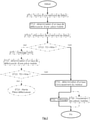
- the essential technical functions of the diagnostic means and of the control means are shown in solid lines on the figure 2 . Additional functions are shown in dotted lines.
- the diagnostic means and the control means consist of a microprocessor associated with a program memory.
- the microprocessor is connected to the engine system computer controlling the overall operation of the engine system to be cleaned; the engine system computer notably controls the movements of the moving parts.
- the microprocessor is also connected to the cleaning fluid injection device, the operation of which it controls.
- the program memory stores a program executable by the microprocessor; said program comprises a plurality of lines of code suitable for implementing the functions of the diagnostic means and the functions of the control means within the scope of the invention.
- a diagnosis of the motorization system is carried out before it is cleaned.
- a defective rate of a moving part is determined (ET12).
- the microprocessor transmits to the computer of the motorization system instructions to control the movement of said moving part between its two extreme positions, the other moving parts being kept stationary; the engine system computer sets said part in motion then, after movement of said moving part, transmits to the microprocessor a measurement of the two extreme positions of said moving part; the microcontroller then calculates the defect rate of the said part concerned.
- the two extreme positions correspond to the open position and the closed position of the moving part considered (EGR valve, intake valve, moving member of the variable geometry turbocharger, etc.).
- EGR valve intake valve
- moving member of the variable geometry turbocharger etc.
- the latter is movable along a theoretical maximum travel C0 between a position where the fluid flow rate is equal to 100% of the theoretical flow rate of the pipe upstream of the moving part. and a position where the fluid flow through the moving part is zero.
- soot accumulates around the moving parts, so that a moving part opens less and less well (the maximum value of the flow it allows decreases) and closes less and less well (the minimum value of the fluid flow is no longer zero and increases) so that its travel C between its two extreme positions decreases over time.
- TD (C0-C)/C0.
- the stroke of the part may correspond to a linear distance measured for example in millimeters; this is the case for example of the moving member of the turbocharger or of the EGR valve.
- Other mobile parts are mobile in rotation, in this case the stroke of the part can correspond to an angular distance measured for example in degrees; this is the case for example of the inlet valve.
- the degree of opening (expressed in %) of a moving part can be used as a measure of the stroke of the moving part;
- the opening rate of a valve defines, for example, the proportion of gas that the valve lets through; the rate opening of a valve is zero when it is completely closed and it is equal to 100% when the valve is completely open; the stroke of the valve is thus equal to the maximum value of the opening rate minus the minimum value of the opening rate at the time of the diagnosis, the theoretical maximum stroke being equal to 100%.
- the determination of the defective rate is repeated for each moving part to diagnose the moving parts one after another.
- the order in which moving parts are diagnosed can be preset and stored in program memory.
- the microcontroller transmits instructions to the usual computer of the motorization system to read a fault memory of said computer (ET11). If it receives in return information relating to a fault in one of the moving parts, for example the EGR valve, the moving part presenting a fault is diagnosed first. After reading the fault memory (ET11) or after determining the fault rate (ET12), the fault memory can be erased (ET12b).
- the microprocessor verifies whether the rate of defect TD of a moving part is greater than a maximum admissible value (ET13).
- the defect rate of the same moving part is determined again (ET22): the microprocessor transmits instructions to the computer to control the movement of the same moving part between its two extreme positions and receives in return, after movement (or absence of movement) of the part, a measurement of its two extreme positions; if the two extreme positions of the part are the same as before, the defect rate determined again is greater than the maximum admissible value (ET23), this means that the initial cleaning did not improve the general condition of the room ; the microprocessor considers in this case that even intensive and long cleaning has little chance of being effective and it transmits on a display means an alert informing that the moving part must be replaced (defective part alert).
- the initial cleaning sequence is for example brief, of the order of 10 to 30 minutes, but intense with a flow rate of cleaning fluid of the order of 700 / hour, with in parallel a setting in motion of the part in opening or closing alternately every 2 to 5 minutes.
- the control means determines the rate of fouling of the overall motorization system (ET31) according to the rate of defect of each moving part.
- the rate of fouling of the motorization system is chosen equal to the greatest rate of defect among the rates of defect of all the moving parts taken into account.
- the defect rate of each moving part is weighted by a coefficient representing the importance of a defect of said moving part in the normal operation of the engine or the importance of the consequences of a defection of the said moving part on the operation of the engine (permanent damage to the engine, significant replacement cost of the moving part, significant pollution generated, etc.), then the fouling rate of the motorization system is determined according to the rates defects of the moving parts taken into account.
- the control means then controls the implementation of the cleaning sequence at the injection device, according to the determined injection parameters (ET32).
- three cleaning cycles are carried out successively, each lasting from 30 minutes to 1 hour 30 minutes, cycles during which the cleaning fluid used is a gaseous mixture of oxygen and hydrogen in a stoichiometric mixture. with a flow rate of 500 I/h to 700 I/h.
- the EGR valve is set in motion: the valve is open by 50% (it allows 50% of the gas it receives to pass) at the start of the 1st cycle for a first predefined time of 2 to 10 min, then the EGR valve is open by 0% (valve closed) for a second predefined time of l order of 2 to 10 min, then, for a third predefined time of the order of 5 to 15 min, the EGR valve is alternately opened and closed (extreme positions) approximately every 0.5 s (alternating operation)
- the intake valve is set in motion in a similar manner.
- the moving member of the turbocharger is set in motion in a similar manner. For each cycle, the flow rate, the temperature and the pressure of the cleaning fluid are adjusted according to the rate of defect of the moving part set in motion during said cycle.
Landscapes
- Engineering & Computer Science (AREA)
- Chemical & Material Sciences (AREA)
- Combustion & Propulsion (AREA)
- Mechanical Engineering (AREA)
- General Engineering & Computer Science (AREA)
- Output Control And Ontrol Of Special Type Engine (AREA)
- Exhaust-Gas Circulating Devices (AREA)
- Combined Controls Of Internal Combustion Engines (AREA)
- Exhaust Gas After Treatment (AREA)
- Electrical Control Of Air Or Fuel Supplied To Internal-Combustion Engine (AREA)
- Vehicle Cleaning, Maintenance, Repair, Refitting, And Outriggers (AREA)
- Manufacture Of Motors, Generators (AREA)
Claims (12)
- Reinigungsanlage eines Antriebssystems, wobei das Antriebssystem einen Verbrennungsmotor und einen Gaszirkulationskreislauf beinhaltet, wobei der Motor eine Vielzahl von Einlässen (2a, 2b), die dazu bestimmt sind, brennbare Produkte aufzunehmen, und einen Abgasauslass (3) beinhaltet, wobei der Gaszirkulationskreislauf eine Vielzahl von Leitungen (6) und eine Vielzahl von beweglichen Teilen (7, 7a, 7b, 7c) beinhaltet, die gemeinsam angeordnet sind, um ein geeignetes Gasgemisch zu einem der Einlässe des Motors zu führen, wobei die Reinigungsanlage eine Einspritzvorrichtung beinhaltet, die dazu angepasst ist, eine Sequenz zur Reinigung des Antriebssystems durchzuführen, indem sie ein Reinigungsfluid in einen der Einlässe des Motors einspritzt,
wobei die Anlage dadurch gekennzeichnet ist, dass sie ferner Folgendes beinhaltet: ein Diagnosemittel, das dazu angeordnet ist, einen Verschmutzungsgrad des Antriebssystems in Abhängigkeit von einem Fehlergrad mindestens eines der beweglichen Teile (7, 7a, 7b, 7c) zu bestimmen, und ein Steuermittel, das dazu angeordnet ist, der Einspritzvorrichtung Reinigungsparameter zur Durchführung der Reinigungssequenz bereitzustellen, wobei die Reinigungsparameter von dem Verschmutzungsgrad des Antriebssystems abhängen. - Anlage nach Anspruch 1, die für ein Antriebssystem angepasst ist, das einen Gaszirkulationskreislauf beinhaltet, der dazu angeordnet ist, eine geeignete Gasmischung, die einen Teil der am Motorauslass verfügbaren Abgase beinhaltet, zu dem Einlass des Motors zu führen.
- Anlage nach einem der Ansprüche 1 oder 2, wobei die Vielzahl von beweglichen Teilen des Gaszirkulationskreislaufs ein Einlassventil (7c) und/oder ein AGR-Ventil (7a) und/oder ein mobiles Organ eines Turbokompressors (7b) beinhaltet.
- Anlage nach einem der Ansprüche 1 bis 3, wobei das Diagnosemittel dazu angeordnet ist, eine Bewegung eines beweglichen Teils (7, 7a, 7b, 7c) zwischen zwei Endstellungen anzusteuern, wobei die anderen beweglichen Teile der Vielzahl von beweglichen Teilen in einer festen Stellung gehalten werden, und den Fehlergrad des beweglichen Teils in Abhängigkeit von einem zwischen den zwei Endstellungen des beweglichen Teils zurückgelegten Weg und in Abhängigkeit von einem theoretischen Maximalweg zu bestimmen.
- Anlage nach dem vorhergehenden Anspruch, wobei das Diagnosemittel ferner dazu angeordnet ist, einen Fehlerspeicher, der mit dem Antriebssystem assoziiert ist, auszulesen, und, wenn eine Information über einen Fehler eines beweglichen Teils (7, 7a, 7b, 7c) in dem Fehlerspeicher aufgezeichnet ist, dazu angeordnet ist, den Fehlergrad des beweglichen Teils in Abhängigkeit von dem zwischen den zwei Endstellungen des beweglichen Teils zurückgelegten Weg, in Abhängigkeit von dem theoretischen Maximalweg und in Abhängigkeit von der Information über den Fehler, die aus dem Fehlerspeicher ausgelesen wurde, zu bestimmen.
- Anlage nach einem der Ansprüche 4 oder 5, wobei das Diagnosemittel dazu angeordnet ist, den Fehlergrad jedes beweglichen Teils (7, 7a, 7b, 7c) nacheinander zu bestimmen.
- Anlage nach einem der vorhergehenden Ansprüche, wobei das Diagnosemittel dazu angeordnet ist, falls der Fehlergrad eines beweglichen Teils (7, 7a, 7b, 7c) größer als ein vordefinierter Wert ist, die Durchführung einer Vorreinigungssequenz anzusteuern und dann den Fehlergrad des beweglichen Teils erneut zu bestimmen und eine Warnung bezüglich eines fehlerhaften beweglichen Teils auszugeben, falls der erneut bestimmte Fehlergrad größer als oder gleich dem für das bewegliche Teil zuvor bestimmten Fehlergrad ist.
- Anlage nach einem der vorhergehenden Ansprüche, wobei das Steuermittel zu Folgendem angeordnet ist:• Bestimmen des Verschmutzungsgrads des Antriebssystems in Abhängigkeit von den Fehlergraden der beweglichen Teile (7, 7a, 7b, 7c) der Vielzahl von beweglichen Teilen,• in Abhängigkeit von dem Verschmutzungsgrad des Antriebssystems, Bestimmen von Reinigungsparametern einer Reinigungssequenz, die eine Vielzahl von Reinigungszyklen beinhaltet, wobei die Reinigungsparameter eine Anzahl von Reinigungszyklen und Einspritzparameter beinhalten, die insbesondere für jeden Reinigungszyklus eine Dauer des Reinigungszyklus und/oder eine während des Reinigungszyklus einzuspritzende Fluidmenge beinhalten, und• Ansteuern der Durchführung der Reinigungssequenz durch die Einspritzvorrichtung gemäß den bestimmten Einspritzparametern.
- Anlage nach Anspruch 8, wobei die an die Einspritzvorrichtung übertragenen Einspritzparameter für jeden Reinigungszyklus ferner Folgendes beinhalten:• eine Temperatur und/oder einen Druck des eingespritzten Fluids und/oder• einen Zustand des einzuspritzenden Fluids und/oder• eine Zusammensetzung des einzuspritzenden Fluids, insbesondere einen Wasserstoffantei I.
- Anlage nach einem der Ansprüche 8 bis 9, wobei das Steuermittel ferner zu Folgendem angeordnet ist:• in Abhängigkeit von dem Verschmutzungsgrad des Antriebssystems und/oder der Fehlergrade der beweglichen Teile der Vielzahl von beweglichen Teilen, Bestimmen von Bewegungsparametern mindestens eines oder jedes beweglichen Teils (7, 7a, 7b, 7c) während einer Reinigungssequenz und• entsprechend den bestimmten Bewegungsparametern, Ansteuern der Bewegung des oder jedes beweglichen Teils während der Reinigungssequenz, die durch die Einspritzvorrichtung durchgeführt wird.
- Anlage nach einem der Ansprüche 8 bis 10, wobei das Diagnosemittel dazu angeordnet ist, den Verschmutzungsgrad eines Motors in Abhängigkeit von dem Fehlergrad mindestens eines beweglichen Teils (oder der beweglichen Teile) der Vielzahl von beweglichen Teilen (7, 7a, 7b, 7c) und in Abhängigkeit von inhärenten Parametern des Antriebssystems, umfassend den Motor, zu bestimmen.
- Anlage nach einem der Ansprüche 8 bis 11, wobei das Diagnosemittel dazu angeordnet ist, den Verschmutzungsgrad eines Motors zusätzlich in Abhängigkeit von Nutzungsbedingungen des Antriebssystems zu bestimmen.
Applications Claiming Priority (2)
| Application Number | Priority Date | Filing Date | Title |
|---|---|---|---|
| FR1770270A FR3064026B1 (fr) | 2017-03-20 | 2017-03-20 | Amelioration d'une installation de nettoyage d'un moteur a combustion interne |
| PCT/IB2018/051821 WO2018172910A1 (fr) | 2017-03-20 | 2018-03-19 | Amélioration d'une installation de nettoyage d'un moteur à combustion interne |
Publications (2)
| Publication Number | Publication Date |
|---|---|
| EP3601764A1 EP3601764A1 (de) | 2020-02-05 |
| EP3601764B1 true EP3601764B1 (de) | 2022-01-19 |
Family
ID=58707936
Family Applications (1)
| Application Number | Title | Priority Date | Filing Date |
|---|---|---|---|
| EP18712474.8A Active EP3601764B1 (de) | 2017-03-20 | 2018-03-19 | Verbesserte reinigungsanlage für eine brennkraftmaschine |
Country Status (14)
| Country | Link |
|---|---|
| US (1) | US10774738B2 (de) |
| EP (1) | EP3601764B1 (de) |
| JP (1) | JP7261171B2 (de) |
| CN (1) | CN110799740B (de) |
| AU (1) | AU2018238292B2 (de) |
| CA (1) | CA3056036A1 (de) |
| ES (1) | ES2909562T3 (de) |
| FR (1) | FR3064026B1 (de) |
| MY (1) | MY201523A (de) |
| PL (1) | PL3601764T3 (de) |
| PT (1) | PT3601764T (de) |
| RU (1) | RU2756721C2 (de) |
| TW (1) | TWI757453B (de) |
| WO (1) | WO2018172910A1 (de) |
Families Citing this family (1)
| Publication number | Priority date | Publication date | Assignee | Title |
|---|---|---|---|---|
| FR3110636B1 (fr) | 2020-05-20 | 2022-04-15 | Alphagreen Dev | Procédé de décalaminage d’un moteur thermique par injection d'hydrogène et station de décalaminage pour sa mise en œuvre. |
Family Cites Families (21)
| Publication number | Priority date | Publication date | Assignee | Title |
|---|---|---|---|---|
| FR1502059A (fr) | 1966-10-05 | 1967-11-18 | élément porteur des vérins d'un mécanisme élévateur de benne baschante à basculement limité | |
| AT400473B (de) | 1989-08-03 | 1996-01-25 | Avl Verbrennungskraft Messtech | Brennkraftmaschine mit abgasturbolader |
| US6073638A (en) * | 1997-11-24 | 2000-06-13 | Wynn Oil Company | Method and apparatus for cleaning an automotive engine |
| US6079379A (en) * | 1998-04-23 | 2000-06-27 | Design & Manufacturing Solutions, Inc. | Pneumatically controlled compressed air assisted fuel injection system |
| FI114112B (fi) * | 2001-03-14 | 2004-08-13 | Marioff Corp Oy | Menetelmä polttomoottorin pakokaasujen puhdistamiseksi ja laitteisto kostean ilman syöttämiseksi polttomoottoriin |
| JP2005030339A (ja) * | 2003-07-09 | 2005-02-03 | Hitachi Ltd | エンジンの制御装置 |
| FR2880069B1 (fr) * | 2004-12-29 | 2007-04-20 | Renault Sas | Systeme et procede de nettoyage d'un circuit de recyclage de gaz d'echappement de moteur diesel |
| FR2883925B1 (fr) * | 2005-04-05 | 2007-05-11 | Inst Francais Du Petrole | Composant balaye par des gaz d'echappement, notamment composant d'un groupe moteur, et procede pour revetir un tel composant |
| JP2006327363A (ja) * | 2005-05-25 | 2006-12-07 | Toyota Motor Corp | 車両の制御装置 |
| JP4803007B2 (ja) * | 2006-12-04 | 2011-10-26 | トヨタ自動車株式会社 | 内燃機関の制御装置 |
| JP4881222B2 (ja) * | 2007-05-17 | 2012-02-22 | シェブロンジャパン株式会社 | ガソリンエンジンの内面部品の洗浄方法 |
| FR2931897A1 (fr) * | 2008-06-03 | 2009-12-04 | Renault Sas | Procede de decrassage d'une vanne de recirculation des gaz d'echappement et moteur a combustion interne |
| JP2010090833A (ja) * | 2008-10-09 | 2010-04-22 | Aisan Ind Co Ltd | 内燃機関の吸気装置 |
| US8423269B2 (en) * | 2009-07-08 | 2013-04-16 | Cummins Inc. | Exhaust gas recirculation valve contaminant removal |
| CN201521353U (zh) * | 2009-10-14 | 2010-07-07 | 詹招淦 | 车辆进气、排气系统除碳除垢的装置 |
| CN202047912U (zh) * | 2011-04-27 | 2011-11-23 | 友荃科技实业股份有限公司 | 侦测引擎负压的氢氧除碳装置 |
| DE102011082089A1 (de) * | 2011-09-02 | 2013-03-07 | Abb Turbo Systems Ag | Reinigungsvorrichtung einer Abgasturbine |
| JP2013096364A (ja) * | 2011-11-04 | 2013-05-20 | Toyota Motor Corp | 内燃機関用気体流量制御弁 |
| DE102013201532A1 (de) * | 2013-01-30 | 2014-07-31 | Mtu Friedrichshafen Gmbh | Verfahren zum Reinigen eines Brennraums einer Brennkraftmaschine und Brennkraftmaschine |
| JP6071639B2 (ja) * | 2013-02-27 | 2017-02-01 | 三菱重工業株式会社 | 過給機の洗浄装置及び方法 |
| JP2016173047A (ja) * | 2015-03-17 | 2016-09-29 | 富士重工業株式会社 | スロットル装置 |
-
2017
- 2017-03-20 FR FR1770270A patent/FR3064026B1/fr not_active Expired - Fee Related
-
2018
- 2018-03-19 EP EP18712474.8A patent/EP3601764B1/de active Active
- 2018-03-19 MY MYPI2019005404A patent/MY201523A/en unknown
- 2018-03-19 PT PT187124748T patent/PT3601764T/pt unknown
- 2018-03-19 CA CA3056036A patent/CA3056036A1/fr active Pending
- 2018-03-19 ES ES18712474T patent/ES2909562T3/es active Active
- 2018-03-19 RU RU2019131104A patent/RU2756721C2/ru active
- 2018-03-19 WO PCT/IB2018/051821 patent/WO2018172910A1/fr not_active Ceased
- 2018-03-19 US US16/495,975 patent/US10774738B2/en active Active
- 2018-03-19 JP JP2019551556A patent/JP7261171B2/ja active Active
- 2018-03-19 PL PL18712474.8T patent/PL3601764T3/pl unknown
- 2018-03-19 CN CN201880028367.0A patent/CN110799740B/zh not_active Expired - Fee Related
- 2018-03-19 AU AU2018238292A patent/AU2018238292B2/en not_active Ceased
- 2018-03-20 TW TW107109525A patent/TWI757453B/zh not_active IP Right Cessation
Non-Patent Citations (1)
| Title |
|---|
| None * |
Also Published As
| Publication number | Publication date |
|---|---|
| PL3601764T3 (pl) | 2022-07-18 |
| MY201523A (en) | 2024-02-27 |
| CN110799740A (zh) | 2020-02-14 |
| CA3056036A1 (fr) | 2018-09-27 |
| FR3064026B1 (fr) | 2019-03-22 |
| EP3601764A1 (de) | 2020-02-05 |
| JP7261171B2 (ja) | 2023-04-19 |
| TWI757453B (zh) | 2022-03-11 |
| PT3601764T (pt) | 2022-03-31 |
| RU2019131104A (ru) | 2021-04-21 |
| RU2756721C2 (ru) | 2021-10-04 |
| CN110799740B (zh) | 2021-10-19 |
| JP2020514624A (ja) | 2020-05-21 |
| RU2019131104A3 (de) | 2021-08-02 |
| WO2018172910A1 (fr) | 2018-09-27 |
| FR3064026A1 (fr) | 2018-09-21 |
| TW201843387A (zh) | 2018-12-16 |
| US20200131986A1 (en) | 2020-04-30 |
| AU2018238292A1 (en) | 2019-10-03 |
| AU2018238292B2 (en) | 2023-08-17 |
| ES2909562T3 (es) | 2022-05-09 |
| US10774738B2 (en) | 2020-09-15 |
Similar Documents
| Publication | Publication Date | Title |
|---|---|---|
| FR2899932A1 (fr) | Procede et dispositif de controle de la regeneration d'un systeme de depollution | |
| EP2520785B1 (de) | Verfahren zur Abschätzung der Verdünnung eines Kraftstoffes im Öl eines Verbrennungsmotors | |
| EP2283212A1 (de) | Verfahren und vorrichtung zur erkennung der verbrennung bei einem partikelfilter | |
| EP3601764B1 (de) | Verbesserte reinigungsanlage für eine brennkraftmaschine | |
| FR3028044A1 (fr) | Procede de validation d’une huile moteur ou d’un element d’un moteur thermique suralimente | |
| EP2182191B1 (de) | Verfahren zur Überwachung eines Partikelfilters | |
| EP1524425B1 (de) | Steuerungsverfahren für die Regeneration eines Partikelfilters | |
| EP3601763B1 (de) | Verbesserte reinigungsanlage für eine brennkraftmaschine | |
| EP3077637A1 (de) | Verfahren zur optimierung der detektion eines fehlerhaften katalysators | |
| WO2009133281A1 (fr) | Systeme et procede de diagnostic de l'etat de fonctionnement d'un dispositif d'admission en gaz d'echappement pour moteur a combustion interne de vehicule automobile | |
| EP1650420B1 (de) | Vorrichtung und Verfahren zur Regelung der Partikelfilterregeneration einer Brennkraftmaschine | |
| FR2979091A1 (fr) | Procede et dispositif de controle pour la maitrise des emballements de la reaction de regeneration d'un filtre a particules dans un vehicule automobile hybride | |
| EP1413720B1 (de) | Verfahren zum Ermitteln der Innentemperatur eines Partikelfilters, Verfahren zur Steuerung der Regeneration des Partikelfilters, sowie Steuerungssystem und Partikelfilter | |
| EP1106804A1 (de) | Verfahren zur Steuerung einer Antriebseinheit eines Kraftfahrzeuges zur Anreicherung der Abgase während der Regeneration einer Stickoxidfalle | |
| EP2299094A1 (de) | Regelverfahren für einen aufgeladenen Dieselmotor mit Niederdruck-Abgasrückführung | |
| FR2915514A1 (fr) | Systeme et procede d'estimation de la masse de particules accumulees dans un fitre a particules d'un moteur a combustion interne | |
| FR2877588A1 (fr) | Procede d'oxydation pour l'epuration de gaz d'echappement d'un moteur a combustion et systeme d'aide au fonctionnement d'un catalyseur d'oxydation | |
| EP3237732A1 (de) | Verfahren zur diagnose einer stickoxidfalle und zugehörige vorrichtung | |
| FR2879245A1 (fr) | Dispositif de determination de la masse instantanee de particules retenues par un filtre a particules et utilisation du dispositif. | |
| FR2876732A1 (fr) | Systeme et procede de regulation de la regeneration d'un filtre a particules de moteur a combustion interne | |
| FR2879655A1 (fr) | Dispositif de regeneration d'un filtre a particules pour vehicule automobile et procede correspondant | |
| FR2948418A3 (fr) | Procede de gestion de la purge d'un piege a oxydes d'azote. | |
| FR2881180A1 (fr) | Procede de commande d'un moteur a combustion | |
| FR2921429A1 (fr) | Systeme et procede de desulfatation d'un piege a oxydes d'azote pour moteur a combustion interne | |
| FR2879653A1 (fr) | Dispositif d'estimation d'une quantite de particules dans un filtre a particules de vehicule automobile |
Legal Events
| Date | Code | Title | Description |
|---|---|---|---|
| STAA | Information on the status of an ep patent application or granted ep patent |
Free format text: STATUS: UNKNOWN |
|
| STAA | Information on the status of an ep patent application or granted ep patent |
Free format text: STATUS: THE INTERNATIONAL PUBLICATION HAS BEEN MADE |
|
| PUAI | Public reference made under article 153(3) epc to a published international application that has entered the european phase |
Free format text: ORIGINAL CODE: 0009012 |
|
| STAA | Information on the status of an ep patent application or granted ep patent |
Free format text: STATUS: REQUEST FOR EXAMINATION WAS MADE |
|
| 17P | Request for examination filed |
Effective date: 20190916 |
|
| AK | Designated contracting states |
Kind code of ref document: A1 Designated state(s): AL AT BE BG CH CY CZ DE DK EE ES FI FR GB GR HR HU IE IS IT LI LT LU LV MC MK MT NL NO PL PT RO RS SE SI SK SM TR |
|
| AX | Request for extension of the european patent |
Extension state: BA ME |
|
| DAV | Request for validation of the european patent (deleted) | ||
| DAX | Request for extension of the european patent (deleted) | ||
| STAA | Information on the status of an ep patent application or granted ep patent |
Free format text: STATUS: EXAMINATION IS IN PROGRESS |
|
| 17Q | First examination report despatched |
Effective date: 20201118 |
|
| GRAP | Despatch of communication of intention to grant a patent |
Free format text: ORIGINAL CODE: EPIDOSNIGR1 |
|
| STAA | Information on the status of an ep patent application or granted ep patent |
Free format text: STATUS: GRANT OF PATENT IS INTENDED |
|
| INTG | Intention to grant announced |
Effective date: 20210811 |
|
| GRAS | Grant fee paid |
Free format text: ORIGINAL CODE: EPIDOSNIGR3 |
|
| GRAA | (expected) grant |
Free format text: ORIGINAL CODE: 0009210 |
|
| STAA | Information on the status of an ep patent application or granted ep patent |
Free format text: STATUS: THE PATENT HAS BEEN GRANTED |
|
| AK | Designated contracting states |
Kind code of ref document: B1 Designated state(s): AL AT BE BG CH CY CZ DE DK EE ES FI FR GB GR HR HU IE IS IT LI LT LU LV MC MK MT NL NO PL PT RO RS SE SI SK SM TR |
|
| REG | Reference to a national code |
Ref country code: GB Ref legal event code: FG4D Free format text: NOT ENGLISH |
|
| REG | Reference to a national code |
Ref country code: CH Ref legal event code: EP |
|
| REG | Reference to a national code |
Ref country code: DE Ref legal event code: R096 Ref document number: 602018029751 Country of ref document: DE |
|
| REG | Reference to a national code |
Ref country code: AT Ref legal event code: REF Ref document number: 1463919 Country of ref document: AT Kind code of ref document: T Effective date: 20220215 |
|
| REG | Reference to a national code |
Ref country code: IE Ref legal event code: FG4D Free format text: LANGUAGE OF EP DOCUMENT: FRENCH |
|
| REG | Reference to a national code |
Ref country code: PT Ref legal event code: SC4A Ref document number: 3601764 Country of ref document: PT Date of ref document: 20220331 Kind code of ref document: T Free format text: AVAILABILITY OF NATIONAL TRANSLATION Effective date: 20220324 |
|
| REG | Reference to a national code |
Ref country code: RO Ref legal event code: EPE |
|
| REG | Reference to a national code |
Ref country code: NL Ref legal event code: FP |
|
| REG | Reference to a national code |
Ref country code: ES Ref legal event code: FG2A Ref document number: 2909562 Country of ref document: ES Kind code of ref document: T3 Effective date: 20220509 |
|
| REG | Reference to a national code |
Ref country code: LT Ref legal event code: MG9D |
|
| PG25 | Lapsed in a contracting state [announced via postgrant information from national office to epo] |
Ref country code: SE Free format text: LAPSE BECAUSE OF FAILURE TO SUBMIT A TRANSLATION OF THE DESCRIPTION OR TO PAY THE FEE WITHIN THE PRESCRIBED TIME-LIMIT Effective date: 20220119 Ref country code: RS Free format text: LAPSE BECAUSE OF FAILURE TO SUBMIT A TRANSLATION OF THE DESCRIPTION OR TO PAY THE FEE WITHIN THE PRESCRIBED TIME-LIMIT Effective date: 20220119 Ref country code: NO Free format text: LAPSE BECAUSE OF FAILURE TO SUBMIT A TRANSLATION OF THE DESCRIPTION OR TO PAY THE FEE WITHIN THE PRESCRIBED TIME-LIMIT Effective date: 20220419 Ref country code: LT Free format text: LAPSE BECAUSE OF FAILURE TO SUBMIT A TRANSLATION OF THE DESCRIPTION OR TO PAY THE FEE WITHIN THE PRESCRIBED TIME-LIMIT Effective date: 20220119 Ref country code: HR Free format text: LAPSE BECAUSE OF FAILURE TO SUBMIT A TRANSLATION OF THE DESCRIPTION OR TO PAY THE FEE WITHIN THE PRESCRIBED TIME-LIMIT Effective date: 20220119 Ref country code: BG Free format text: LAPSE BECAUSE OF FAILURE TO SUBMIT A TRANSLATION OF THE DESCRIPTION OR TO PAY THE FEE WITHIN THE PRESCRIBED TIME-LIMIT Effective date: 20220419 |
|
| PG25 | Lapsed in a contracting state [announced via postgrant information from national office to epo] |
Ref country code: LV Free format text: LAPSE BECAUSE OF FAILURE TO SUBMIT A TRANSLATION OF THE DESCRIPTION OR TO PAY THE FEE WITHIN THE PRESCRIBED TIME-LIMIT Effective date: 20220119 Ref country code: GR Free format text: LAPSE BECAUSE OF FAILURE TO SUBMIT A TRANSLATION OF THE DESCRIPTION OR TO PAY THE FEE WITHIN THE PRESCRIBED TIME-LIMIT Effective date: 20220420 Ref country code: FI Free format text: LAPSE BECAUSE OF FAILURE TO SUBMIT A TRANSLATION OF THE DESCRIPTION OR TO PAY THE FEE WITHIN THE PRESCRIBED TIME-LIMIT Effective date: 20220119 |
|
| PG25 | Lapsed in a contracting state [announced via postgrant information from national office to epo] |
Ref country code: IS Free format text: LAPSE BECAUSE OF FAILURE TO SUBMIT A TRANSLATION OF THE DESCRIPTION OR TO PAY THE FEE WITHIN THE PRESCRIBED TIME-LIMIT Effective date: 20220519 |
|
| REG | Reference to a national code |
Ref country code: DE Ref legal event code: R097 Ref document number: 602018029751 Country of ref document: DE |
|
| PG25 | Lapsed in a contracting state [announced via postgrant information from national office to epo] |
Ref country code: SM Free format text: LAPSE BECAUSE OF FAILURE TO SUBMIT A TRANSLATION OF THE DESCRIPTION OR TO PAY THE FEE WITHIN THE PRESCRIBED TIME-LIMIT Effective date: 20220119 Ref country code: SK Free format text: LAPSE BECAUSE OF FAILURE TO SUBMIT A TRANSLATION OF THE DESCRIPTION OR TO PAY THE FEE WITHIN THE PRESCRIBED TIME-LIMIT Effective date: 20220119 Ref country code: MC Free format text: LAPSE BECAUSE OF FAILURE TO SUBMIT A TRANSLATION OF THE DESCRIPTION OR TO PAY THE FEE WITHIN THE PRESCRIBED TIME-LIMIT Effective date: 20220119 Ref country code: EE Free format text: LAPSE BECAUSE OF FAILURE TO SUBMIT A TRANSLATION OF THE DESCRIPTION OR TO PAY THE FEE WITHIN THE PRESCRIBED TIME-LIMIT Effective date: 20220119 Ref country code: DK Free format text: LAPSE BECAUSE OF FAILURE TO SUBMIT A TRANSLATION OF THE DESCRIPTION OR TO PAY THE FEE WITHIN THE PRESCRIBED TIME-LIMIT Effective date: 20220119 |
|
| REG | Reference to a national code |
Ref country code: CH Ref legal event code: PL |
|
| PLBE | No opposition filed within time limit |
Free format text: ORIGINAL CODE: 0009261 |
|
| STAA | Information on the status of an ep patent application or granted ep patent |
Free format text: STATUS: NO OPPOSITION FILED WITHIN TIME LIMIT |
|
| PG25 | Lapsed in a contracting state [announced via postgrant information from national office to epo] |
Ref country code: AL Free format text: LAPSE BECAUSE OF FAILURE TO SUBMIT A TRANSLATION OF THE DESCRIPTION OR TO PAY THE FEE WITHIN THE PRESCRIBED TIME-LIMIT Effective date: 20220119 |
|
| 26N | No opposition filed |
Effective date: 20221020 |
|
| PG25 | Lapsed in a contracting state [announced via postgrant information from national office to epo] |
Ref country code: LU Free format text: LAPSE BECAUSE OF NON-PAYMENT OF DUE FEES Effective date: 20220319 Ref country code: LI Free format text: LAPSE BECAUSE OF NON-PAYMENT OF DUE FEES Effective date: 20220331 Ref country code: IE Free format text: LAPSE BECAUSE OF NON-PAYMENT OF DUE FEES Effective date: 20220319 Ref country code: CH Free format text: LAPSE BECAUSE OF NON-PAYMENT OF DUE FEES Effective date: 20220331 |
|
| PG25 | Lapsed in a contracting state [announced via postgrant information from national office to epo] |
Ref country code: SI Free format text: LAPSE BECAUSE OF FAILURE TO SUBMIT A TRANSLATION OF THE DESCRIPTION OR TO PAY THE FEE WITHIN THE PRESCRIBED TIME-LIMIT Effective date: 20220119 |
|
| REG | Reference to a national code |
Ref country code: AT Ref legal event code: UEP Ref document number: 1463919 Country of ref document: AT Kind code of ref document: T Effective date: 20220119 |
|
| PG25 | Lapsed in a contracting state [announced via postgrant information from national office to epo] |
Ref country code: MK Free format text: LAPSE BECAUSE OF FAILURE TO SUBMIT A TRANSLATION OF THE DESCRIPTION OR TO PAY THE FEE WITHIN THE PRESCRIBED TIME-LIMIT Effective date: 20220119 Ref country code: CY Free format text: LAPSE BECAUSE OF FAILURE TO SUBMIT A TRANSLATION OF THE DESCRIPTION OR TO PAY THE FEE WITHIN THE PRESCRIBED TIME-LIMIT Effective date: 20220119 |
|
| PG25 | Lapsed in a contracting state [announced via postgrant information from national office to epo] |
Ref country code: HU Free format text: LAPSE BECAUSE OF FAILURE TO SUBMIT A TRANSLATION OF THE DESCRIPTION OR TO PAY THE FEE WITHIN THE PRESCRIBED TIME-LIMIT; INVALID AB INITIO Effective date: 20180319 |
|
| PG25 | Lapsed in a contracting state [announced via postgrant information from national office to epo] |
Ref country code: TR Free format text: LAPSE BECAUSE OF FAILURE TO SUBMIT A TRANSLATION OF THE DESCRIPTION OR TO PAY THE FEE WITHIN THE PRESCRIBED TIME-LIMIT Effective date: 20220119 |
|
| PG25 | Lapsed in a contracting state [announced via postgrant information from national office to epo] |
Ref country code: MT Free format text: LAPSE BECAUSE OF FAILURE TO SUBMIT A TRANSLATION OF THE DESCRIPTION OR TO PAY THE FEE WITHIN THE PRESCRIBED TIME-LIMIT Effective date: 20220119 |
|
| PGFP | Annual fee paid to national office [announced via postgrant information from national office to epo] |
Ref country code: DE Payment date: 20250331 Year of fee payment: 8 |
|
| PGFP | Annual fee paid to national office [announced via postgrant information from national office to epo] |
Ref country code: ES Payment date: 20250401 Year of fee payment: 8 |
|
| PGFP | Annual fee paid to national office [announced via postgrant information from national office to epo] |
Ref country code: IT Payment date: 20250327 Year of fee payment: 8 |
|
| PGFP | Annual fee paid to national office [announced via postgrant information from national office to epo] |
Ref country code: GB Payment date: 20260330 Year of fee payment: 9 |
|
| PGFP | Annual fee paid to national office [announced via postgrant information from national office to epo] |
Ref country code: AT Payment date: 20260319 Year of fee payment: 9 |
|
| PGFP | Annual fee paid to national office [announced via postgrant information from national office to epo] |
Ref country code: RO Payment date: 20260313 Year of fee payment: 9 Ref country code: BE Payment date: 20260325 Year of fee payment: 9 |
|
| PGFP | Annual fee paid to national office [announced via postgrant information from national office to epo] |
Ref country code: NL Payment date: 20260330 Year of fee payment: 9 |
|
| PGFP | Annual fee paid to national office [announced via postgrant information from national office to epo] |
Ref country code: FR Payment date: 20260330 Year of fee payment: 9 |
|
| PGFP | Annual fee paid to national office [announced via postgrant information from national office to epo] |
Ref country code: PT Payment date: 20260310 Year of fee payment: 9 Ref country code: CZ Payment date: 20260310 Year of fee payment: 9 |
|
| PGFP | Annual fee paid to national office [announced via postgrant information from national office to epo] |
Ref country code: PL Payment date: 20260310 Year of fee payment: 9 |