EP3601623B2 - Procédé et dispositif de refroidissement d'une bande d'acier en defilement dans une section de refroidissement d'une ligne continue - Google Patents
Procédé et dispositif de refroidissement d'une bande d'acier en defilement dans une section de refroidissement d'une ligne continue Download PDFInfo
- Publication number
- EP3601623B2 EP3601623B2 EP18715224.4A EP18715224A EP3601623B2 EP 3601623 B2 EP3601623 B2 EP 3601623B2 EP 18715224 A EP18715224 A EP 18715224A EP 3601623 B2 EP3601623 B2 EP 3601623B2
- Authority
- EP
- European Patent Office
- Prior art keywords
- solution
- formic acid
- liquid
- cooling
- advantageously
- Prior art date
- Legal status (The legal status is an assumption and is not a legal conclusion. Google has not performed a legal analysis and makes no representation as to the accuracy of the status listed.)
- Active
Links
Images
Classifications
-
- C—CHEMISTRY; METALLURGY
- C21—METALLURGY OF IRON
- C21D—MODIFYING THE PHYSICAL STRUCTURE OF FERROUS METALS; GENERAL DEVICES FOR HEAT TREATMENT OF FERROUS OR NON-FERROUS METALS OR ALLOYS; MAKING METAL MALLEABLE, e.g. BY DECARBURISATION OR TEMPERING
- C21D1/00—General methods or devices for heat treatment, e.g. annealing, hardening, quenching or tempering
- C21D1/56—General methods or devices for heat treatment, e.g. annealing, hardening, quenching or tempering characterised by the quenching agents
-
- C—CHEMISTRY; METALLURGY
- C21—METALLURGY OF IRON
- C21D—MODIFYING THE PHYSICAL STRUCTURE OF FERROUS METALS; GENERAL DEVICES FOR HEAT TREATMENT OF FERROUS OR NON-FERROUS METALS OR ALLOYS; MAKING METAL MALLEABLE, e.g. BY DECARBURISATION OR TEMPERING
- C21D9/00—Heat treatment, e.g. annealing, hardening, quenching or tempering, adapted for particular articles; Furnaces therefor
- C21D9/52—Heat treatment, e.g. annealing, hardening, quenching or tempering, adapted for particular articles; Furnaces therefor for wires; for strips ; for rods of unlimited length
- C21D9/54—Furnaces for treating strips or wire
- C21D9/56—Continuous furnaces for strip or wire
- C21D9/573—Continuous furnaces for strip or wire with cooling
-
- C—CHEMISTRY; METALLURGY
- C21—METALLURGY OF IRON
- C21D—MODIFYING THE PHYSICAL STRUCTURE OF FERROUS METALS; GENERAL DEVICES FOR HEAT TREATMENT OF FERROUS OR NON-FERROUS METALS OR ALLOYS; MAKING METAL MALLEABLE, e.g. BY DECARBURISATION OR TEMPERING
- C21D1/00—General methods or devices for heat treatment, e.g. annealing, hardening, quenching or tempering
- C21D1/56—General methods or devices for heat treatment, e.g. annealing, hardening, quenching or tempering characterised by the quenching agents
- C21D1/60—Aqueous agents
-
- C—CHEMISTRY; METALLURGY
- C21—METALLURGY OF IRON
- C21D—MODIFYING THE PHYSICAL STRUCTURE OF FERROUS METALS; GENERAL DEVICES FOR HEAT TREATMENT OF FERROUS OR NON-FERROUS METALS OR ALLOYS; MAKING METAL MALLEABLE, e.g. BY DECARBURISATION OR TEMPERING
- C21D1/00—General methods or devices for heat treatment, e.g. annealing, hardening, quenching or tempering
- C21D1/62—Quenching devices
- C21D1/667—Quenching devices for spray quenching
-
- C—CHEMISTRY; METALLURGY
- C21—METALLURGY OF IRON
- C21D—MODIFYING THE PHYSICAL STRUCTURE OF FERROUS METALS; GENERAL DEVICES FOR HEAT TREATMENT OF FERROUS OR NON-FERROUS METALS OR ALLOYS; MAKING METAL MALLEABLE, e.g. BY DECARBURISATION OR TEMPERING
- C21D8/00—Modifying the physical properties by deformation combined with, or followed by, heat treatment
- C21D8/02—Modifying the physical properties by deformation combined with, or followed by, heat treatment during manufacturing of plates or strips
- C21D8/0205—Modifying the physical properties by deformation combined with, or followed by, heat treatment during manufacturing of plates or strips of ferrous alloys
-
- C—CHEMISTRY; METALLURGY
- C23—COATING METALLIC MATERIAL; COATING MATERIAL WITH METALLIC MATERIAL; CHEMICAL SURFACE TREATMENT; DIFFUSION TREATMENT OF METALLIC MATERIAL; COATING BY VACUUM EVAPORATION, BY SPUTTERING, BY ION IMPLANTATION OR BY CHEMICAL VAPOUR DEPOSITION, IN GENERAL; INHIBITING CORROSION OF METALLIC MATERIAL OR INCRUSTATION IN GENERAL
- C23C—COATING METALLIC MATERIAL; COATING MATERIAL WITH METALLIC MATERIAL; SURFACE TREATMENT OF METALLIC MATERIAL BY DIFFUSION INTO THE SURFACE, BY CHEMICAL CONVERSION OR SUBSTITUTION; COATING BY VACUUM EVAPORATION, BY SPUTTERING, BY ION IMPLANTATION OR BY CHEMICAL VAPOUR DEPOSITION, IN GENERAL
- C23C2/00—Hot-dipping or immersion processes for applying the coating material in the molten state without affecting the shape; Apparatus therefor
- C23C2/34—Hot-dipping or immersion processes for applying the coating material in the molten state without affecting the shape; Apparatus therefor characterised by the shape of the material to be treated
- C23C2/36—Elongated material
- C23C2/40—Plates; Strips
-
- C—CHEMISTRY; METALLURGY
- C23—COATING METALLIC MATERIAL; COATING MATERIAL WITH METALLIC MATERIAL; CHEMICAL SURFACE TREATMENT; DIFFUSION TREATMENT OF METALLIC MATERIAL; COATING BY VACUUM EVAPORATION, BY SPUTTERING, BY ION IMPLANTATION OR BY CHEMICAL VAPOUR DEPOSITION, IN GENERAL; INHIBITING CORROSION OF METALLIC MATERIAL OR INCRUSTATION IN GENERAL
- C23G—CLEANING OR DE-GREASING OF METALLIC MATERIAL BY CHEMICAL METHODS OTHER THAN ELECTROLYSIS
- C23G1/00—Cleaning or pickling metallic material with solutions or molten salts
- C23G1/02—Cleaning or pickling metallic material with solutions or molten salts with acid solutions
- C23G1/08—Iron or steel
- C23G1/088—Iron or steel solutions containing organic acids
-
- C—CHEMISTRY; METALLURGY
- C23—COATING METALLIC MATERIAL; COATING MATERIAL WITH METALLIC MATERIAL; CHEMICAL SURFACE TREATMENT; DIFFUSION TREATMENT OF METALLIC MATERIAL; COATING BY VACUUM EVAPORATION, BY SPUTTERING, BY ION IMPLANTATION OR BY CHEMICAL VAPOUR DEPOSITION, IN GENERAL; INHIBITING CORROSION OF METALLIC MATERIAL OR INCRUSTATION IN GENERAL
- C23G—CLEANING OR DE-GREASING OF METALLIC MATERIAL BY CHEMICAL METHODS OTHER THAN ELECTROLYSIS
- C23G3/00—Apparatus for cleaning or pickling metallic material
- C23G3/02—Apparatus for cleaning or pickling metallic material for cleaning wires, strips, filaments continuously
- C23G3/023—Apparatus for cleaning or pickling metallic material for cleaning wires, strips, filaments continuously by spraying
-
- C—CHEMISTRY; METALLURGY
- C23—COATING METALLIC MATERIAL; COATING MATERIAL WITH METALLIC MATERIAL; CHEMICAL SURFACE TREATMENT; DIFFUSION TREATMENT OF METALLIC MATERIAL; COATING BY VACUUM EVAPORATION, BY SPUTTERING, BY ION IMPLANTATION OR BY CHEMICAL VAPOUR DEPOSITION, IN GENERAL; INHIBITING CORROSION OF METALLIC MATERIAL OR INCRUSTATION IN GENERAL
- C23G—CLEANING OR DE-GREASING OF METALLIC MATERIAL BY CHEMICAL METHODS OTHER THAN ELECTROLYSIS
- C23G3/00—Apparatus for cleaning or pickling metallic material
- C23G3/02—Apparatus for cleaning or pickling metallic material for cleaning wires, strips, filaments continuously
- C23G3/027—Associated apparatus, e.g. for pretreating or after-treating
- C23G3/028—Associated apparatus, e.g. for pretreating or after-treating for thermal or mechanical pretreatment
Definitions
- the invention relates to the wet cooling sections of continuous lines for annealing or galvanizing steel strips.
- galvanizing the present description refers to all dipping coatings, whether zinc, aluminum, zinc and aluminum alloy coatings, or any other type of coating.
- the steel strip can typically enter at a temperature between 500 °C and 1000 °C, for example 800 °C, and can leave at a temperature close to room temperature or at an intermediate temperature.
- Gas cooling typically carried out by spraying a high-speed, high-hydrogen N 2 H 2 mixture onto the steel strip, allows cooling rates of up to 200 °C/s to be achieved for 1 mm thick steel strips. Since this cooling is carried out using a reducing gas, the steel strip is not oxidized after passing through this type of cooling. Galvanizing the strip is then possible without any intermediate chemical step, such as pickling. However, since the cooling rate is limited to 200 °C/s, gas cooling does not allow the production of steels with high mechanical and metallurgical properties that require higher cooling rates.
- An aim of the invention is to propose a method for cooling a steel strip which improves the performance of the methods according to the state of the art.
- Another aim of the invention is to propose a cooling method with greater efficiency than the methods according to the state of the art.
- Another aim of the invention is to propose a cooling method that is less expensive than the methods according to the state of the art.
- the present invention also relates to a cooling device according to the terms of claim 7.
- the formic acid concentration of said solution is between 0.1% and 6% by mass of the solution.
- the liquid of said mixture has a formic acid concentration also between 0.1% and 6% by mass.
- the gas present in the mixture to be projected is advantageously an inert gas, for example nitrogen, or hydrogenated nitrogen.
- Tests were carried out by the applicant on different types of steel, standard steels and steels alloyed with conventional alloying elements such as manganese and silicon, with the aim of determining the ideal concentration of formic acid. These tests consist, for example, of placing a sample measuring 100 mm x 40 mm x 1 mm between two connecting pieces and rapidly heating it to a temperature of 800 °C, under a N 2 H 2 atmosphere containing 5% H 2 and a dew point of -60 °C, by circulating an electric current through the sample. A formic acid solution is then sprayed onto the sample for a set period of time so that it reaches a temperature of 50 °C.
- the sample is reheated to a temperature of 80 °C while it is flushed with N 2 H 2 at 5% H 2 and a dew point of -60 °C.
- concentration of formic acid in the liquid solution is adjusted according to the content of alloying elements with high redox potential, such as aluminum, manganese, or silicon, in the steel. The higher it is, the higher the concentration of formic acid in the solution.
- the formic acid concentration is between 0.1 and 5.5%, advantageously between 0.1 and 5%, advantageously between 0.1 and 4.5%, advantageously between 0.1 and 4%, advantageously between 0.1 and 3.5%, advantageously between 0.1 and 3%, advantageously between 0.1 and 2.5%, advantageously between 0.15% and 2.5%, advantageously between 0.2 and 2.5%, advantageously between 0.3% and 2%, advantageously between 0.35% and 2.5%, advantageously between 0.4% and 2.5%, advantageously between 0.45% and 2.5% by mass of the solution.
- the formic acid concentration is between 0.46% and 2.4%, advantageously between 0.47% and 2.3%, advantageously between 0.48% and 2.2%, advantageously between 0.49% and 2.1% by mass of the solution. Even more advantageously, the formic acid concentration is between 0.5% and 2% by mass of the solution.
- a formic acid solution with a concentration of between 0.5% and 2% by mass of the solution makes it possible to treat steel grades that are not very sensitive to oxidation, for example with a low manganese, aluminum or silicon content.
- the solution to be projected has a pH between 1.5 and 3.
- the formic acid solution used to rapidly cool the strip does not require any further chemical treatment of the strip after cooling. It also does not require rinsing the strip with water after rapid cooling. Only drying can be carried out. It is therefore particularly advantageous for galvanizing lines since the strip can be immersed in the zinc bath immediately after wet cooling, after simply drying the strip.
- Formic acid is the simplest of the carboxylic acids. Because of its very simple chemical composition, the risk of creating complex carbon deposits adhering to the steel strip or on the walls of equipment, which would prevent the galvanizing step from proceeding without further intermediate treatment, is very limited. More complex acids, such as citric acid, can leave significant carbon deposits on the strip, which can prevent proper galvanizing.
- Formic acid also called methanoic acid, with the chemical formula HCOOH or CH 2 O 2 , and products of its decomposition, have highly reducing properties that are ideal for the application of the invention.
- the solution to be projected can take the form of fog, water knife, or other forms.
- the decomposition of formic acid is mainly by decarboxylation while it is mainly by dehydration when formic acid is in gaseous form.
- the aqueous solution to be sprayed is sprayed onto the steel strip by spraying
- the solution to be sprayed is an aqueous solution.
- An aqueous solution has the advantage, compared to other solutions, of being more environmentally friendly, as it does not produce toxic or harmful emissions during its use.
- An aqueous solution is also less expensive than other solutions.
- the aqueous solution to be sprayed can be composed mainly of demineralized water. This further limits deposits on the steel strip. This solution does not result in discharges that contravene the environmental standards of steel-producing countries, nor does it result in excessively high additional costs per ton of steel produced.
- part of the solution produced by the thermochemical reaction of the sprayed solution and the steel strip is recovered in a recirculation unit, preferably in a recirculation tank, and the solution to be sprayed is taken from a projection unit, preferably in a projection tank, connected to the recirculation unit. It is thus possible to reuse the sprayed solution, i.e. to minimize operating costs.
- the flow rate of solution to be used to cool the strip is between 200 and 1000 m 3 /h, and more generally around 500 m 3 /h.
- Only a small proportion of the sprayed solution is altered by its chemical reaction with the steel strip and its thermal decomposition. In order not to reach prohibitive consumption and production costs, it is therefore important to reuse, or even recycle a very large part of this solution.
- at least 50% of the solution is recycled. Even more advantageously, at least 60%, advantageously at least 70%, advantageously at least 80%, advantageously at least 90% of the solution is recycled.
- At least 91%, advantageously at least 92%, advantageously at least 93%, advantageously at least 94%, advantageously at least 95%, advantageously at least 96%, advantageously at least 97%, advantageously at least 98%, advantageously at least 99% of the solution is recycled. In an even more advantageous embodiment, 100% of the solution is recycled.
- the method according to the invention comprises a continuous or periodic control, for example every hour, of the liquid solution to be projected, for example present in the recirculation unit, which control comprises a measurement of at least one physicochemical data of said solution chosen from the group comprising the pH, the density and the formic acid concentration, or a combination of these physicochemical data, and, when this measurement does not belong to a predetermined tolerance range, a predetermined volume of the liquid solution, for example present in the recirculation unit, is taken and the same predetermined volume of a formic acid solution is injected into the projection unit (13), said predetermined volume of an injected formic acid solution having a formic acid concentration such that the liquid solution to be projected has, after injection, a formic acid concentration of between 0.1% and 6% by mass.
- the liquid solution to be projected has, after injection, a formic acid concentration of between 0.1 and 5.5%, advantageously between 0.1 and 5%, advantageously between 0.1 and 4.5%, advantageously between 0.1 and 4%, advantageously between 0.1 and 3.5%, advantageously between 0.1 and 3%, advantageously between 0.1 and 2.5%, advantageously between 0.15% and 2.5%, advantageously between 0.2 and 2.5%, advantageously between 0.3% and 2%, advantageously between 0.35% and 2.5%, advantageously between 0.4% and 2.5%, advantageously between 0.45% and 2.5% by mass.
- the liquid solution to be sprayed has, after injection, a formic acid concentration of between 0.46% and 2.4%, advantageously between 0.47% and 2.3%, advantageously between 0.48% and 2.2%, advantageously between 0.49% and 2.1% by mass.
- the liquid solution to be sprayed has, after injection, a formic acid concentration of between 0.5% and 2% by mass.
- the predetermined volume of the solution taken from the recirculation unit is determined according to the deviation in formic acid concentration between the measured value and the minimum value of the predetermined tolerance range and the formic acid concentration of the injected solution so that the formic acid concentration of the sprayed solution again has a desired concentration.
- the tolerance range is, for example, +/- 10% of the set value, whether this is, for example, a formic acid concentration value, a density value or a pH value.
- the formic acid concentration and the tolerance range can be adjusted according to the additives in the steel constituting the strip and in particular its sensitivity to oxidation.
- the formic acid concentration and the tolerance range can be adjusted depending on the configuration of the line, its operating mode and the nature of the steels treated, depending on whether these promote the formation of oxides on the surface of the strip to a greater or lesser extent.
- the formic acid concentration and tolerance range can, for example, be determined by tests carried out on samples subjected to a thermal cycle representative of those carried out on the line.
- the recirculation system reduces formic acid consumption. However, the collected solution is lost. This is why the invention proposes, according to a particular embodiment, to recycle this collected solution.
- the collected solution can then be treated by oxidation of (CHO 2 ) 2 Fe with hydrogen peroxide, also referred to as hydrogen peroxide in this description, in order to obtain the following reaction: 2(CHO 2 ) 2 Fe + H 2 O 2 + 2CH 2 O 2 ⁇ 2(CHO 2 ) 3 Fe + 2H 2 O
- the sampled solution is treated by oxidation with hydrogen peroxide and then filtered to extract iron III hydroxides and other alloying elements, the injected solution coming from a recirculation of the filtered solution or from a new solution.
- new solution refers to a solution having a formic acid concentration of between 0.1% and 6% by mass of the solution.
- the new solution has a formic acid concentration of between 0.1 and 5.5%, advantageously between 0.1 and 5%, advantageously between 0.1 and 4.5%, advantageously between 0.1 and 4%, advantageously between 0.1 and 3.5%, advantageously between 0.1 and 3%, advantageously between 0.1 and 2.5%, advantageously between 0.15% and 2.5%, advantageously between 0.2 and 2.5%, advantageously between 0.3% and 2%, advantageously between 0.35% and 2.5%, advantageously between 0.4% and 2.5%, advantageously between 0.45% and 2.5% by mass of the solution.
- the new solution has a formic acid concentration of between 0.46% and 2.4%, advantageously between 0.47% and 2.3%, advantageously between 0.48% and 2.2%, advantageously between 0.49% and 2.1% by mass of the solution. Even more advantageously, the new solution has a formic acid concentration of between 0.5% and 2% by mass of the solution.
- the collected solution can be treated with hydrogen peroxide to obtain a mixture of formic acid and iron III hydroxide. This mixture can then be filtered to separate the formic acid from the iron III hydroxides.
- the treated and filtered formic acid can be reused and reinjected into the circuit.
- This method has the advantage of allowing the precise measurement of the quantity of hydrogen peroxide needed to react with the quantity of iron III hydroxide present in the solution. This not only allows the chemical reaction to be controlled so that all the hydrogen peroxide is consumed, but above all, it allows for a reaction that is almost instantaneous.
- the system's consumption is therefore mainly hydrogen peroxide and the only discharges, apart from gaseous discharges, are iron III hydroxides and other alloying elements from the steel strips.
- the formic acid solution can be fully or partially recirculated.
- Oxidation with hydrogen peroxide can restore the desired formic acid concentration.
- Filtration can remove metal oxides, for example, using a filter press.
- the waste only contains iron III hydroxides and other metal alloying elements.
- the dissolved oxygen present in the solution is a source of oxidation of the strip. By removing this source of oxidation, the surface condition of the strip is even better.
- the solution taken from the recirculation unit can be treated by deoxygenation before being sprayed.
- the level of dissolved oxygen remaining in the solution to be projected can be less than 1 ppm.
- Dissolved oxygen can be removed from the solution by a system of membranes flushed with nitrogen on one side and a vacuum on the other.
- dissolved oxygen can be removed from the solution by bubbling nitrogen, or another neutral gas, through the solution to enhance natural deoxygenation.
- the method may further comprise a collection of vapors which results from the projection of the solution to be projected onto the steel strip, a condensation of said collected vapors, and an injection of said condensed vapors into a fluid circuit from which said solution to be projected is taken.
- Vapor collection can be carried out by a vapor collector arranged above a unit for projecting the solution to be projected.
- the gas resulting from the condensation of the vapors can be sent to a chimney.
- Condensation of the collected vapors can be achieved by a washing tower.
- a cooling device arranged to cool a steel strip moving in a cooling section of a continuous line
- means arranged to implement a cooling method, as described in claims 1 to 6, by spraying onto said steel strip an aqueous solution, said aqueous solution being a liquid solution or a mixture of a liquid solution and a gas, the formic acid concentration of said aqueous solution being between 0.1% and 6% by mass
- the device comprising a membrane system arranged to deoxygenate said solution.
- the means of the device also comprise a membrane system arranged to deoxygenate the solution, said membranes being swept with nitrogen on one side with a vacuum on the other.
- the means of the device according to the invention may comprise an enclosure comprising a unit for projecting a solution to be projected, preferably nozzles, arranged to project a liquid, or a mixture comprising a gas and a liquid, onto the steel strip.
- the membrane system designed to remove dissolved oxygen from the solution to be sprayed is arranged upstream of these nozzles.
- the means of the device may comprise, at the outlet of the enclosure, in the direction of travel of the strip, a set of liquid knives arranged to remove most of the runoff liquid present on the strip.
- the means of the device may comprise, downstream of the set of liquid knives, a set of gas knives arranged to remove the liquid still present on the strip.
- the means of the device may comprise, downstream of the enclosure and where appropriate the set of liquid knives, and where appropriate all or part of the set of gas knives, a return tank arranged to collect the cooling liquid projected by the nozzles.
- the return tank may be arranged so as to be below the path of the strip leaving the enclosure.
- the return tank may include a second set of gas knives arranged to remove liquid still present on the belt.
- the means of the device may comprise a recirculation tank and means for transferring liquid from the return tank to the recirculation tank.
- the liquid transfer means may include a filter arranged to remove metal particles present in the solution.
- the means of the device may comprise supply circuits comprising a pump and an exchanger for supplying the projection unit.
- the feed circuit may include a bypass circuit allowing a liquid portion pumped by the pump in the recirculation tank to be sent to another tank.
- the means of the device may comprise means for actuating the bypass circuits, said means being actuated when it is necessary to renew a portion of the liquid contained in the cooling section in order to maintain the performance thereof within a predetermined operating range.
- the membrane system can be positioned immediately upstream of the spray unit, with the pump being able to be placed upstream of the membrane system, in which case the formic acid solution management circuit does not need to be isolated from oxygen sources.
- the pump can also be placed between the membrane system and the projection system, which allows the pressure in the membranes to be lowered.
- the membrane system can be positioned on a recirculation loop on the projection tank or between the projection tank and the recirculation tank.
- the rest of the solution management circuit is preferably oxygen-tight.
- All tanks can be gas-tight and flushed with an inert atmosphere, preferably nitrogen.
- the means of the device may comprise a treatment assembly in which the sampled solution may be treated with hydrogen peroxide.
- the treatment assembly may include a filter, for example a filter press, the waste from which may be removed by conveyors.
- the treatment assembly may include means for injecting a solution at the outlet of the filter into the projection tank.
- the invention consists, apart from the arrangements set out above, of a certain number of other arrangements which will be discussed more explicitly below with regard to an exemplary embodiment described with reference to the attached drawing, but which is in no way limiting.
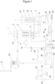
- Figure 1 is a schematic view of an embodiment of a cooling section according to the invention.
- This embodiment being in no way limiting, it will be possible in particular to produce variants of the invention comprising only a selection of characteristics described below, as described or generalized, isolated from the other characteristics described, if this selection of characteristics is sufficient to confer a technical advantage or to differentiate the invention compared to the state of the art.
- a cooling section of a continuous galvanizing line comprising a first part 2 in which a steel strip 1 running vertically from top to bottom is cooled by spraying a liquid according to the invention.
- a bubbling 31 with nitrogen or another neutral gas is placed in a projection tank 13 to amplify the natural deoxygenation. A measurement of the dissolved oxygen level in the solution is carried out in the projection tank 13 by means of a probe 35.
- part 2 At the outlet of part 2, in the direction of travel of the strip, there is a set 5 of liquid knives intended to remove most of the runoff liquid present on the strip.
- the set 5 of liquid knives is followed, in the direction of travel of the strip, by a set 6 of gas knives intended to remove the liquid still present on the strip.
- the strip then passes through a return tank 7 in which the cooling liquid projected by the nozzles 3 and the set 5 of liquid knives is collected.
- a second set 8 of gas knives is intended to remove the liquid still present on the strip.
- the strip then passes through a part 9 equipped with heating tubes 10 making it possible to remove any trace of liquid on the strip.
- the strip passes through an airlock 11 for separating the atmosphere between the wet parts 2, 7, 9 and parts 12 located downstream in the direction of travel of the strip.
- an injection and/or a suction of gas makes it possible to reinforce the separation of atmospheres between the sections upstream and downstream of the airlock.
- the liquid projected onto the belt by the nozzles 3 and the set 5 of liquid knives is collected in the return tank 7 and then sent to the projection tank 13.
- the liquid is transferred from the return tank 7 into a recirculation tank 27.
- This tank is equipped with compartments 32 in cascade to maintain a maximum number of particles in the first compartments.
- Electromagnets 33 placed under the tank 27 and a system of drawers 34 make it possible to recover and evacuate the metal particles without having to empty the tank.
- the liquid then passes through a set 28 of external filters in order to eliminate the residual metal particles before being returned to the projection tank 13 by means of a pump 30.
- the set 28 of external filters and the pump 30 are doubled in order to ensure the maintenance of this equipment without stopping the installation.
- Supply circuits 14 comprising a pump 15 and a heat exchanger 16 make it possible to supply the rows of nozzles 3 of the part 2 with cooling liquid at the required pressure and temperature from the liquid contained in the projection tank 13.
- the supply circuits 14 comprise a bypass circuit 17 making it possible to send a liquid portion pumped in the tank 13 to a tank 18.
- the bypass circuit 17 originates in the recirculation tank 27.
- the bypass circuit 17 is actuated when it is necessary to renew a portion of the liquid contained in the cooling section in order to maintain its performance within the desired operating range.
- a vapor collector 19 is placed in part 2 above the rows of nozzles 3.
- the collected vapors are sent to a wet scrubber 20 in which the vapors are condensed and sent to the tank 18.
- the gas freed from its vapors is sent to a chimney 21.
- the liquid collected in the tank 18 is sent to a treatment unit 22 in which the used formic acid solution is dosed with hydrogen peroxide in order to obtain a mixture of formic acid and iron III hydroxide and steel alloying elements.
- This mixture is then filtered by a filter press (not shown) in order to separate the formic acid from the iron III hydroxides, the latter being evacuated by conveyors 23.
- the regenerated formic acid is used again and reinjected as a new solution by means of a circuit 24 into a tank 25.
- a supply of new formic acid is also carried out in this tank 25 by means of a circuit 26.
Landscapes
- Chemical & Material Sciences (AREA)
- Engineering & Computer Science (AREA)
- Materials Engineering (AREA)
- Mechanical Engineering (AREA)
- Metallurgy (AREA)
- Organic Chemistry (AREA)
- Thermal Sciences (AREA)
- Physics & Mathematics (AREA)
- Crystallography & Structural Chemistry (AREA)
- Chemical Kinetics & Catalysis (AREA)
- General Chemical & Material Sciences (AREA)
- Cleaning And De-Greasing Of Metallic Materials By Chemical Methods (AREA)
- Heat Treatment Of Strip Materials And Filament Materials (AREA)
- Coating With Molten Metal (AREA)
- Heat Treatments In General, Especially Conveying And Cooling (AREA)
Priority Applications (2)
| Application Number | Priority Date | Filing Date | Title |
|---|---|---|---|
| RS20210951A RS62170B2 (sr) | 2017-03-22 | 2018-03-22 | Metoda i uređaj za hlađenje pokretne čelične trake u sekciji za hlađenje neprekidne linije |
| PL18715224.4T PL3601623T5 (pl) | 2017-03-22 | 2018-03-22 | Sposób i urządzenie do schładzania taśmy stalowej przesuwającej się w sekcji schładzania linii ciągłej |
Applications Claiming Priority (2)
| Application Number | Priority Date | Filing Date | Title |
|---|---|---|---|
| FR1752352A FR3064279B1 (fr) | 2017-03-22 | 2017-03-22 | Procede et dispositif de refroidissement d'une bande d'acier en defilement dans une section de refroidissement d'une ligne continue |
| PCT/FR2018/050705 WO2018172713A1 (fr) | 2017-03-22 | 2018-03-22 | Procede et dispositif de refroidissement d'une bande d'acier en defilement dans une section de refroidissement d'une ligne continue |
Publications (3)
| Publication Number | Publication Date |
|---|---|
| EP3601623A1 EP3601623A1 (fr) | 2020-02-05 |
| EP3601623B1 EP3601623B1 (fr) | 2021-04-28 |
| EP3601623B2 true EP3601623B2 (fr) | 2025-03-26 |
Family
ID=58739209
Family Applications (1)
| Application Number | Title | Priority Date | Filing Date |
|---|---|---|---|
| EP18715224.4A Active EP3601623B2 (fr) | 2017-03-22 | 2018-03-22 | Procédé et dispositif de refroidissement d'une bande d'acier en defilement dans une section de refroidissement d'une ligne continue |
Country Status (12)
| Country | Link |
|---|---|
| US (1) | US11162156B2 (pl) |
| EP (1) | EP3601623B2 (pl) |
| JP (2) | JP2020520409A (pl) |
| KR (2) | KR20230065369A (pl) |
| CN (1) | CN110546283A (pl) |
| ES (1) | ES2882291T5 (pl) |
| FI (1) | FI3601623T4 (pl) |
| FR (1) | FR3064279B1 (pl) |
| PL (1) | PL3601623T5 (pl) |
| PT (1) | PT3601623T (pl) |
| RS (1) | RS62170B2 (pl) |
| WO (1) | WO2018172713A1 (pl) |
Families Citing this family (5)
| Publication number | Priority date | Publication date | Assignee | Title |
|---|---|---|---|---|
| FR3064279B1 (fr) * | 2017-03-22 | 2020-06-26 | Fives Stein | Procede et dispositif de refroidissement d'une bande d'acier en defilement dans une section de refroidissement d'une ligne continue |
| FR3104178B1 (fr) | 2019-12-09 | 2022-12-02 | Fives Stein | Dispositif et procede de traitement thermique des aciers comprenant un refroidissement humide |
| CN111304424A (zh) * | 2020-04-27 | 2020-06-19 | 唐山曹妃甸区首燕机械有限公司 | 一种炉鼻子加湿器 |
| CN113604635B (zh) * | 2021-07-27 | 2023-05-09 | 中国华电科工集团有限公司 | 一种用于太阳能集热器制造系统的回火设备及其回火方法 |
| FR3156805B1 (fr) | 2023-12-13 | 2025-11-07 | Fives Stein | Ligne de galvanisation a refroidissement humide |
Citations (5)
| Publication number | Priority date | Publication date | Assignee | Title |
|---|---|---|---|---|
| FR2439825B1 (pl) † | 1978-10-27 | 1984-03-09 | Centre Rech Metallurgique | |
| LU85333A1 (fr) † | 1984-04-24 | 1985-11-27 | Centre Rech Metallurgique | Procede de protection d'un produit metallique contre l'oxydation pendant la trempe |
| WO2006112109A1 (ja) † | 2005-04-12 | 2006-10-26 | Nippon Steel Corporation | 連続熱処理設備の冷却帯における鋼帯の冷却方法及び冷却装置 |
| WO2013136734A1 (ja) † | 2012-03-12 | 2013-09-19 | Jfeスチール株式会社 | デスケーリングシステム |
| WO2014059475A1 (en) † | 2012-10-17 | 2014-04-24 | Bluescope Steel Limited | Method of producing metal-coated steel strip |
Family Cites Families (16)
| Publication number | Priority date | Publication date | Assignee | Title |
|---|---|---|---|---|
| US3729417A (en) * | 1969-02-14 | 1973-04-24 | Toyota Motor Co Ltd | Quenching oil compositions |
| GB1530859A (en) * | 1976-06-23 | 1978-11-01 | Centre Rech Metallurgique | Continuous heat-treatment of steel strip |
| JPS5511155A (en) * | 1978-07-10 | 1980-01-25 | Nippon Steel Corp | Continuous annealing process for cold rolled hoop |
| BE880587A (fr) * | 1979-12-12 | 1980-06-12 | Centre Rech Metallurgique | Installation de traitement thermique en continu de toles d'acier |
| JPS6052531A (ja) * | 1983-09-02 | 1985-03-25 | Nippon Steel Corp | 冷延鋼帯の冷却用水溶液 |
| JPS63192820A (ja) * | 1987-02-06 | 1988-08-10 | Sumitomo Metal Ind Ltd | 鋼材の冷却方法 |
| JPH02170925A (ja) * | 1988-12-21 | 1990-07-02 | Sumitomo Metal Ind Ltd | 連続焼鈍冷間圧延鋼板の製造方法 |
| BE1012753A3 (fr) | 1998-10-01 | 2001-03-06 | Centre Rech Metallurgique | Procede pour le refroidissement non oxydant d'une bande d'acier laminee. |
| JP5086545B2 (ja) * | 2005-04-12 | 2012-11-28 | 新日鉄エンジニアリング株式会社 | 連続熱処理設備の冷却帯における鋼帯の冷却装置 |
| FR2942629B1 (fr) | 2009-03-02 | 2011-11-04 | Cmi Thermline Services | Procede de refroidissement d'une bande metallique circulant dans une section de refroidissement d'une ligne de traitement thermique en continu, et installation de mise en oeuvre dudit procede |
| JP6227248B2 (ja) * | 2012-12-27 | 2017-11-08 | 出光興産株式会社 | 水系冷却剤 |
| FR3014447B1 (fr) * | 2013-12-05 | 2016-02-05 | Fives Stein | Procede et installation de traitement thermique en continu d'une bande d'acier |
| JP6414739B2 (ja) * | 2014-10-14 | 2018-10-31 | 住友電工ウインテック株式会社 | 導体軟化処理装置及び導体軟化処理方法 |
| CN204999977U (zh) | 2015-10-12 | 2016-01-27 | 中钢集团郑州金属制品研究院有限公司 | 钢丝水浴索氏体化热处理超声波清洗作业线 |
| FR3064278B1 (fr) * | 2017-03-22 | 2021-04-23 | Fives Stein | Section et procede de refroidissement d'une ligne continue combinant un refroidissement sec et un refroidissement humide |
| FR3064279B1 (fr) * | 2017-03-22 | 2020-06-26 | Fives Stein | Procede et dispositif de refroidissement d'une bande d'acier en defilement dans une section de refroidissement d'une ligne continue |
-
2017
- 2017-03-22 FR FR1752352A patent/FR3064279B1/fr active Active
-
2018
- 2018-03-22 EP EP18715224.4A patent/EP3601623B2/fr active Active
- 2018-03-22 JP JP2019551699A patent/JP2020520409A/ja active Pending
- 2018-03-22 WO PCT/FR2018/050705 patent/WO2018172713A1/fr not_active Ceased
- 2018-03-22 PL PL18715224.4T patent/PL3601623T5/pl unknown
- 2018-03-22 RS RS20210951A patent/RS62170B2/sr unknown
- 2018-03-22 CN CN201880019710.5A patent/CN110546283A/zh active Pending
- 2018-03-22 PT PT187152244T patent/PT3601623T/pt unknown
- 2018-03-22 KR KR1020237014679A patent/KR20230065369A/ko not_active Ceased
- 2018-03-22 ES ES18715224T patent/ES2882291T5/es active Active
- 2018-03-22 FI FIEP18715224.4T patent/FI3601623T4/en active
- 2018-03-22 US US16/496,221 patent/US11162156B2/en active Active
- 2018-03-22 KR KR1020197030732A patent/KR102556572B1/ko active Active
-
2022
- 2022-08-01 JP JP2022122552A patent/JP7422822B2/ja active Active
Patent Citations (5)
| Publication number | Priority date | Publication date | Assignee | Title |
|---|---|---|---|---|
| FR2439825B1 (pl) † | 1978-10-27 | 1984-03-09 | Centre Rech Metallurgique | |
| LU85333A1 (fr) † | 1984-04-24 | 1985-11-27 | Centre Rech Metallurgique | Procede de protection d'un produit metallique contre l'oxydation pendant la trempe |
| WO2006112109A1 (ja) † | 2005-04-12 | 2006-10-26 | Nippon Steel Corporation | 連続熱処理設備の冷却帯における鋼帯の冷却方法及び冷却装置 |
| WO2013136734A1 (ja) † | 2012-03-12 | 2013-09-19 | Jfeスチール株式会社 | デスケーリングシステム |
| WO2014059475A1 (en) † | 2012-10-17 | 2014-04-24 | Bluescope Steel Limited | Method of producing metal-coated steel strip |
Also Published As
| Publication number | Publication date |
|---|---|
| JP2020520409A (ja) | 2020-07-09 |
| EP3601623B1 (fr) | 2021-04-28 |
| JP2022163112A (ja) | 2022-10-25 |
| PT3601623T (pt) | 2021-07-26 |
| ES2882291T3 (es) | 2021-12-01 |
| US20200017934A1 (en) | 2020-01-16 |
| US11162156B2 (en) | 2021-11-02 |
| PL3601623T3 (pl) | 2021-11-02 |
| WO2018172713A1 (fr) | 2018-09-27 |
| JP7422822B2 (ja) | 2024-01-26 |
| FR3064279A1 (fr) | 2018-09-28 |
| ES2882291T5 (en) | 2025-07-11 |
| KR20190132430A (ko) | 2019-11-27 |
| FR3064279B1 (fr) | 2020-06-26 |
| CN110546283A (zh) | 2019-12-06 |
| EP3601623A1 (fr) | 2020-02-05 |
| RS62170B2 (sr) | 2025-07-31 |
| FI3601623T4 (en) | 2025-05-20 |
| KR102556572B1 (ko) | 2023-07-18 |
| RS62170B1 (sr) | 2021-08-31 |
| PL3601623T5 (pl) | 2025-06-30 |
| KR20230065369A (ko) | 2023-05-11 |
Similar Documents
| Publication | Publication Date | Title |
|---|---|---|
| EP3601623B2 (fr) | Procédé et dispositif de refroidissement d'une bande d'acier en defilement dans une section de refroidissement d'une ligne continue | |
| EP1450934B1 (fr) | Procede pour le traitement de gaz effluent contenant des hydrocarbures | |
| FR2490992A1 (fr) | Procede et installation pour la conversion thermique des pneus usages ou au rebut en matieres utilisables notamment comme combustibles | |
| WO2010142892A1 (fr) | Système et procédé de traitement des fumées et gaz produits par une cuve d'électrolyse lors de la fabrication d'aluminium | |
| EP0252836B1 (fr) | Procédé pour l'élimination rapide de l'hydrogène sulfuré contenu dans le soufre liquide et système catalytique utilisable pour sa mise en oeuvre | |
| EP0766751B1 (fr) | Procede de decapage de materiaux metalliques | |
| EP1262231A1 (fr) | Procédé et dispositif de limination sélective des composés organiques fonctionnalisés d'un milieu liquide | |
| EP1633499B1 (fr) | Procede de traitement de surface ecologique d'un conteneur metallique, associant une action chimique et une action mecanique | |
| CA2764724C (fr) | Systeme et procede de recuperation d'energie | |
| EP0084478B1 (fr) | Procédé de régénération en continu de bains de fluxage dans la galvanisation au trempé de pièces en acier | |
| EP0844292B1 (fr) | Composition et son utilisation pour convertir un gaz contenant de l'hydrogène sulfuré et de l'anhydride sulfureux en soufre | |
| WO2021116594A1 (fr) | Dispositif et procede de traitement thermique des aciers comprenant un refroidissement humide | |
| FR3019367A1 (pl) | ||
| BE1015893A3 (fr) | Procede de controle du decapage des metaux. | |
| FR2818561A1 (fr) | Procede de regeneration d'une solution catalytique redox comprenant la mesure de l'oxygene dissous dans l'effluent de regeneration et son application en desulfuration | |
| JP2021109124A (ja) | 固形物の付着抑制方法および脱硫塔の操業方法 | |
| JP6836026B2 (ja) | 浸炭装置 | |
| FR3011748A1 (fr) | Procede et dispositif de pretraitement de vapeurs d'hydrocarbures lourds en amont d'une unite de traitement final | |
| WO2007055670A1 (fr) | Procede de recyclage de solution de gravure pour le traitement des cartes imprimees | |
| FR2863922A1 (fr) | Procede de recyclage de gaz hautes performances pour four de refusion | |
| FR2874220A1 (fr) | Procede de regeneration des acides d'usinage chimique, installation pour la mise en oeuvre du procede et procede d'usinage chimique associe. | |
| BE530473A (pl) | ||
| FR3037505A1 (fr) | Procede et installation de recuperation d'hydrocarbures utilisant des fumees industrielles riches en co2 |
Legal Events
| Date | Code | Title | Description |
|---|---|---|---|
| STAA | Information on the status of an ep patent application or granted ep patent |
Free format text: STATUS: UNKNOWN |
|
| STAA | Information on the status of an ep patent application or granted ep patent |
Free format text: STATUS: THE INTERNATIONAL PUBLICATION HAS BEEN MADE |
|
| PUAI | Public reference made under article 153(3) epc to a published international application that has entered the european phase |
Free format text: ORIGINAL CODE: 0009012 |
|
| STAA | Information on the status of an ep patent application or granted ep patent |
Free format text: STATUS: REQUEST FOR EXAMINATION WAS MADE |
|
| 17P | Request for examination filed |
Effective date: 20190918 |
|
| AK | Designated contracting states |
Kind code of ref document: A1 Designated state(s): AL AT BE BG CH CY CZ DE DK EE ES FI FR GB GR HR HU IE IS IT LI LT LU LV MC MK MT NL NO PL PT RO RS SE SI SK SM TR |
|
| AX | Request for extension of the european patent |
Extension state: BA ME |
|
| RIN1 | Information on inventor provided before grant (corrected) |
Inventor name: MAGADOUX, ERIC |
|
| DAV | Request for validation of the european patent (deleted) | ||
| DAX | Request for extension of the european patent (deleted) | ||
| STAA | Information on the status of an ep patent application or granted ep patent |
Free format text: STATUS: EXAMINATION IS IN PROGRESS |
|
| 17Q | First examination report despatched |
Effective date: 20200907 |
|
| TPAC | Observations filed by third parties |
Free format text: ORIGINAL CODE: EPIDOSNTIPA |
|
| GRAP | Despatch of communication of intention to grant a patent |
Free format text: ORIGINAL CODE: EPIDOSNIGR1 |
|
| STAA | Information on the status of an ep patent application or granted ep patent |
Free format text: STATUS: GRANT OF PATENT IS INTENDED |
|
| INTG | Intention to grant announced |
Effective date: 20210113 |
|
| GRAS | Grant fee paid |
Free format text: ORIGINAL CODE: EPIDOSNIGR3 |
|
| GRAA | (expected) grant |
Free format text: ORIGINAL CODE: 0009210 |
|
| STAA | Information on the status of an ep patent application or granted ep patent |
Free format text: STATUS: THE PATENT HAS BEEN GRANTED |
|
| AK | Designated contracting states |
Kind code of ref document: B1 Designated state(s): AL AT BE BG CH CY CZ DE DK EE ES FI FR GB GR HR HU IE IS IT LI LT LU LV MC MK MT NL NO PL PT RO RS SE SI SK SM TR |
|
| REG | Reference to a national code |
Ref country code: GB Ref legal event code: FG4D Free format text: NOT ENGLISH |
|
| REG | Reference to a national code |
Ref country code: CH Ref legal event code: EP |
|
| REG | Reference to a national code |
Ref country code: AT Ref legal event code: REF Ref document number: 1387108 Country of ref document: AT Kind code of ref document: T Effective date: 20210515 |
|
| REG | Reference to a national code |
Ref country code: DE Ref legal event code: R096 Ref document number: 602018016228 Country of ref document: DE |
|
| REG | Reference to a national code |
Ref country code: IE Ref legal event code: FG4D Free format text: LANGUAGE OF EP DOCUMENT: FRENCH |
|
| REG | Reference to a national code |
Ref country code: PT Ref legal event code: SC4A Ref document number: 3601623 Country of ref document: PT Date of ref document: 20210726 Kind code of ref document: T Free format text: AVAILABILITY OF NATIONAL TRANSLATION Effective date: 20210721 |
|
| REG | Reference to a national code |
Ref country code: FI Ref legal event code: FGE |
|
| REG | Reference to a national code |
Ref country code: NL Ref legal event code: FP |
|
| REG | Reference to a national code |
Ref country code: SE Ref legal event code: TRGR |
|
| REG | Reference to a national code |
Ref country code: LT Ref legal event code: MG9D |
|
| REG | Reference to a national code |
Ref country code: SK Ref legal event code: T3 Ref document number: E 37787 Country of ref document: SK |
|
| PG25 | Lapsed in a contracting state [announced via postgrant information from national office to epo] |
Ref country code: HR Free format text: LAPSE BECAUSE OF FAILURE TO SUBMIT A TRANSLATION OF THE DESCRIPTION OR TO PAY THE FEE WITHIN THE PRESCRIBED TIME-LIMIT Effective date: 20210428 Ref country code: LT Free format text: LAPSE BECAUSE OF FAILURE TO SUBMIT A TRANSLATION OF THE DESCRIPTION OR TO PAY THE FEE WITHIN THE PRESCRIBED TIME-LIMIT Effective date: 20210428 Ref country code: BG Free format text: LAPSE BECAUSE OF FAILURE TO SUBMIT A TRANSLATION OF THE DESCRIPTION OR TO PAY THE FEE WITHIN THE PRESCRIBED TIME-LIMIT Effective date: 20210728 |
|
| PG25 | Lapsed in a contracting state [announced via postgrant information from national office to epo] |
Ref country code: GR Free format text: LAPSE BECAUSE OF FAILURE TO SUBMIT A TRANSLATION OF THE DESCRIPTION OR TO PAY THE FEE WITHIN THE PRESCRIBED TIME-LIMIT Effective date: 20210729 Ref country code: IS Free format text: LAPSE BECAUSE OF FAILURE TO SUBMIT A TRANSLATION OF THE DESCRIPTION OR TO PAY THE FEE WITHIN THE PRESCRIBED TIME-LIMIT Effective date: 20210828 Ref country code: LV Free format text: LAPSE BECAUSE OF FAILURE TO SUBMIT A TRANSLATION OF THE DESCRIPTION OR TO PAY THE FEE WITHIN THE PRESCRIBED TIME-LIMIT Effective date: 20210428 Ref country code: NO Free format text: LAPSE BECAUSE OF FAILURE TO SUBMIT A TRANSLATION OF THE DESCRIPTION OR TO PAY THE FEE WITHIN THE PRESCRIBED TIME-LIMIT Effective date: 20210728 |
|
| REG | Reference to a national code |
Ref country code: ES Ref legal event code: FG2A Ref document number: 2882291 Country of ref document: ES Kind code of ref document: T3 Effective date: 20211201 |
|
| REG | Reference to a national code |
Ref country code: DE Ref legal event code: R026 Ref document number: 602018016228 Country of ref document: DE |
|
| PG25 | Lapsed in a contracting state [announced via postgrant information from national office to epo] |
Ref country code: RO Free format text: LAPSE BECAUSE OF FAILURE TO SUBMIT A TRANSLATION OF THE DESCRIPTION OR TO PAY THE FEE WITHIN THE PRESCRIBED TIME-LIMIT Effective date: 20210428 Ref country code: DK Free format text: LAPSE BECAUSE OF FAILURE TO SUBMIT A TRANSLATION OF THE DESCRIPTION OR TO PAY THE FEE WITHIN THE PRESCRIBED TIME-LIMIT Effective date: 20210428 Ref country code: SM Free format text: LAPSE BECAUSE OF FAILURE TO SUBMIT A TRANSLATION OF THE DESCRIPTION OR TO PAY THE FEE WITHIN THE PRESCRIBED TIME-LIMIT Effective date: 20210428 Ref country code: EE Free format text: LAPSE BECAUSE OF FAILURE TO SUBMIT A TRANSLATION OF THE DESCRIPTION OR TO PAY THE FEE WITHIN THE PRESCRIBED TIME-LIMIT Effective date: 20210428 |
|
| PLBI | Opposition filed |
Free format text: ORIGINAL CODE: 0009260 |
|
| PLAX | Notice of opposition and request to file observation + time limit sent |
Free format text: ORIGINAL CODE: EPIDOSNOBS2 |
|
| REG | Reference to a national code |
Ref country code: FI Ref legal event code: MDE Opponent name: DREVER INTERNATIONAL |
|
| 26 | Opposition filed |
Opponent name: DREVER INTERNATIONAL Effective date: 20220128 |
|
| PG25 | Lapsed in a contracting state [announced via postgrant information from national office to epo] |
Ref country code: IS Free format text: LAPSE BECAUSE OF FAILURE TO SUBMIT A TRANSLATION OF THE DESCRIPTION OR TO PAY THE FEE WITHIN THE PRESCRIBED TIME-LIMIT Effective date: 20210828 Ref country code: AL Free format text: LAPSE BECAUSE OF FAILURE TO SUBMIT A TRANSLATION OF THE DESCRIPTION OR TO PAY THE FEE WITHIN THE PRESCRIBED TIME-LIMIT Effective date: 20210428 |
|
| PLBB | Reply of patent proprietor to notice(s) of opposition received |
Free format text: ORIGINAL CODE: EPIDOSNOBS3 |
|
| PG25 | Lapsed in a contracting state [announced via postgrant information from national office to epo] |
Ref country code: MC Free format text: LAPSE BECAUSE OF FAILURE TO SUBMIT A TRANSLATION OF THE DESCRIPTION OR TO PAY THE FEE WITHIN THE PRESCRIBED TIME-LIMIT Effective date: 20210428 |
|
| REG | Reference to a national code |
Ref country code: CH Ref legal event code: PL |
|
| PG25 | Lapsed in a contracting state [announced via postgrant information from national office to epo] |
Ref country code: LI Free format text: LAPSE BECAUSE OF NON-PAYMENT OF DUE FEES Effective date: 20220331 Ref country code: IE Free format text: LAPSE BECAUSE OF NON-PAYMENT OF DUE FEES Effective date: 20220322 Ref country code: CH Free format text: LAPSE BECAUSE OF NON-PAYMENT OF DUE FEES Effective date: 20220331 |
|
| PG25 | Lapsed in a contracting state [announced via postgrant information from national office to epo] |
Ref country code: MK Free format text: LAPSE BECAUSE OF FAILURE TO SUBMIT A TRANSLATION OF THE DESCRIPTION OR TO PAY THE FEE WITHIN THE PRESCRIBED TIME-LIMIT Effective date: 20210428 Ref country code: CY Free format text: LAPSE BECAUSE OF FAILURE TO SUBMIT A TRANSLATION OF THE DESCRIPTION OR TO PAY THE FEE WITHIN THE PRESCRIBED TIME-LIMIT Effective date: 20210428 |
|
| APBP | Date of receipt of notice of appeal recorded |
Free format text: ORIGINAL CODE: EPIDOSNNOA2O |
|
| APAH | Appeal reference modified |
Free format text: ORIGINAL CODE: EPIDOSCREFNO |
|
| APAW | Appeal reference deleted |
Free format text: ORIGINAL CODE: EPIDOSDREFNO |
|
| PG25 | Lapsed in a contracting state [announced via postgrant information from national office to epo] |
Ref country code: HU Free format text: LAPSE BECAUSE OF FAILURE TO SUBMIT A TRANSLATION OF THE DESCRIPTION OR TO PAY THE FEE WITHIN THE PRESCRIBED TIME-LIMIT; INVALID AB INITIO Effective date: 20180322 |
|
| APBU | Appeal procedure closed |
Free format text: ORIGINAL CODE: EPIDOSNNOA9O |
|
| REG | Reference to a national code |
Ref country code: CH Ref legal event code: PK Free format text: TITRE |
|
| PG25 | Lapsed in a contracting state [announced via postgrant information from national office to epo] |
Ref country code: MT Free format text: LAPSE BECAUSE OF FAILURE TO SUBMIT A TRANSLATION OF THE DESCRIPTION OR TO PAY THE FEE WITHIN THE PRESCRIBED TIME-LIMIT Effective date: 20210428 |
|
| PUAH | Patent maintained in amended form |
Free format text: ORIGINAL CODE: 0009272 |
|
| STAA | Information on the status of an ep patent application or granted ep patent |
Free format text: STATUS: PATENT MAINTAINED AS AMENDED |
|
| PGFP | Annual fee paid to national office [announced via postgrant information from national office to epo] |
Ref country code: LU Payment date: 20250218 Year of fee payment: 8 Ref country code: NL Payment date: 20250219 Year of fee payment: 8 |
|
| 27A | Patent maintained in amended form |
Effective date: 20250326 |
|
| AK | Designated contracting states |
Kind code of ref document: B2 Designated state(s): AL AT BE BG CH CY CZ DE DK EE ES FI FR GB GR HR HU IE IS IT LI LT LU LV MC MK MT NL NO PL PT RO RS SE SI SK SM TR |
|
| REG | Reference to a national code |
Ref country code: DE Ref legal event code: R102 Ref document number: 602018016228 Country of ref document: DE |
|
| PGFP | Annual fee paid to national office [announced via postgrant information from national office to epo] |
Ref country code: PT Payment date: 20250218 Year of fee payment: 8 Ref country code: DE Payment date: 20250218 Year of fee payment: 8 |
|
| PGFP | Annual fee paid to national office [announced via postgrant information from national office to epo] |
Ref country code: FI Payment date: 20250218 Year of fee payment: 8 |
|
| PGFP | Annual fee paid to national office [announced via postgrant information from national office to epo] |
Ref country code: SE Payment date: 20250218 Year of fee payment: 8 |
|
| PGFP | Annual fee paid to national office [announced via postgrant information from national office to epo] |
Ref country code: AT Payment date: 20250220 Year of fee payment: 8 Ref country code: BE Payment date: 20250218 Year of fee payment: 8 |
|
| PGFP | Annual fee paid to national office [announced via postgrant information from national office to epo] |
Ref country code: PL Payment date: 20250225 Year of fee payment: 8 Ref country code: FR Payment date: 20250219 Year of fee payment: 8 Ref country code: CZ Payment date: 20250219 Year of fee payment: 8 |
|
| PGFP | Annual fee paid to national office [announced via postgrant information from national office to epo] |
Ref country code: GB Payment date: 20250221 Year of fee payment: 8 Ref country code: IT Payment date: 20250218 Year of fee payment: 8 |
|
| PGFP | Annual fee paid to national office [announced via postgrant information from national office to epo] |
Ref country code: RS Payment date: 20250312 Year of fee payment: 8 |
|
| PGFP | Annual fee paid to national office [announced via postgrant information from national office to epo] |
Ref country code: TR Payment date: 20250227 Year of fee payment: 8 |
|
| REG | Reference to a national code |
Ref country code: NL Ref legal event code: FP |
|
| REG | Reference to a national code |
Ref country code: SE Ref legal event code: RPEO |
|
| REG | Reference to a national code |
Ref country code: SK Ref legal event code: T5 Ref document number: E 37787 Country of ref document: SK |
|
| PGFP | Annual fee paid to national office [announced via postgrant information from national office to epo] |
Ref country code: ES Payment date: 20250402 Year of fee payment: 8 |
|
| REG | Reference to a national code |
Ref country code: ES Ref legal event code: DC2A Ref document number: 2882291 Country of ref document: ES Kind code of ref document: T5 Effective date: 20250711 |
|
| PGFP | Annual fee paid to national office [announced via postgrant information from national office to epo] |
Ref country code: SK Payment date: 20250415 Year of fee payment: 8 |