EP3600914B1 - Radsatz für fahrzeuge - Google Patents
Radsatz für fahrzeuge Download PDFInfo
- Publication number
- EP3600914B1 EP3600914B1 EP18739760.9A EP18739760A EP3600914B1 EP 3600914 B1 EP3600914 B1 EP 3600914B1 EP 18739760 A EP18739760 A EP 18739760A EP 3600914 B1 EP3600914 B1 EP 3600914B1
- Authority
- EP
- European Patent Office
- Prior art keywords
- segment
- wheelset
- wheel
- designed
- shaft
- Prior art date
- Legal status (The legal status is an assumption and is not a legal conclusion. Google has not performed a legal analysis and makes no representation as to the accuracy of the status listed.)
- Active
Links
Images
Classifications
-
- B—PERFORMING OPERATIONS; TRANSPORTING
- B60—VEHICLES IN GENERAL
- B60B—VEHICLE WHEELS; CASTORS; AXLES FOR WHEELS OR CASTORS; INCREASING WHEEL ADHESION
- B60B37/00—Wheel-axle combinations, e.g. wheel sets
- B60B37/06—Wheel-axle combinations, e.g. wheel sets the wheels being integral with, or rigidly attached to, hollow axles
-
- B—PERFORMING OPERATIONS; TRANSPORTING
- B60—VEHICLES IN GENERAL
- B60B—VEHICLE WHEELS; CASTORS; AXLES FOR WHEELS OR CASTORS; INCREASING WHEEL ADHESION
- B60B17/00—Wheels characterised by rail-engaging elements
-
- B—PERFORMING OPERATIONS; TRANSPORTING
- B60—VEHICLES IN GENERAL
- B60B—VEHICLE WHEELS; CASTORS; AXLES FOR WHEELS OR CASTORS; INCREASING WHEEL ADHESION
- B60B2900/00—Purpose of invention
- B60B2900/10—Reduction of
- B60B2900/111—Weight
-
- B—PERFORMING OPERATIONS; TRANSPORTING
- B60—VEHICLES IN GENERAL
- B60B—VEHICLE WHEELS; CASTORS; AXLES FOR WHEELS OR CASTORS; INCREASING WHEEL ADHESION
- B60B2900/00—Purpose of invention
- B60B2900/30—Increase in
- B60B2900/331—Safety or security
- B60B2900/3313—Safety or security during maintenance
-
- B—PERFORMING OPERATIONS; TRANSPORTING
- B60—VEHICLES IN GENERAL
- B60B—VEHICLE WHEELS; CASTORS; AXLES FOR WHEELS OR CASTORS; INCREASING WHEEL ADHESION
- B60B2900/00—Purpose of invention
- B60B2900/30—Increase in
- B60B2900/331—Safety or security
- B60B2900/3316—Safety or security by indicating wear, failure or loss
-
- B—PERFORMING OPERATIONS; TRANSPORTING
- B60—VEHICLES IN GENERAL
- B60B—VEHICLE WHEELS; CASTORS; AXLES FOR WHEELS OR CASTORS; INCREASING WHEEL ADHESION
- B60B35/00—Axle units; Parts thereof ; Arrangements for lubrication of axles
- B60B35/02—Dead axles, i.e. not transmitting torque
- B60B35/04—Dead axles, i.e. not transmitting torque straight
-
- B—PERFORMING OPERATIONS; TRANSPORTING
- B60—VEHICLES IN GENERAL
- B60B—VEHICLE WHEELS; CASTORS; AXLES FOR WHEELS OR CASTORS; INCREASING WHEEL ADHESION
- B60B35/00—Axle units; Parts thereof ; Arrangements for lubrication of axles
- B60B35/02—Dead axles, i.e. not transmitting torque
- B60B35/08—Dead axles, i.e. not transmitting torque of closed hollow section
-
- B—PERFORMING OPERATIONS; TRANSPORTING
- B60—VEHICLES IN GENERAL
- B60B—VEHICLE WHEELS; CASTORS; AXLES FOR WHEELS OR CASTORS; INCREASING WHEEL ADHESION
- B60B35/00—Axle units; Parts thereof ; Arrangements for lubrication of axles
- B60B35/12—Torque-transmitting axles
- B60B35/14—Torque-transmitting axles composite or split, e.g. half- axles; Couplings between axle parts or sections
-
- B—PERFORMING OPERATIONS; TRANSPORTING
- B60—VEHICLES IN GENERAL
- B60Y—INDEXING SCHEME RELATING TO ASPECTS CROSS-CUTTING VEHICLE TECHNOLOGY
- B60Y2200/00—Type of vehicle
- B60Y2200/30—Railway vehicles
-
- Y—GENERAL TAGGING OF NEW TECHNOLOGICAL DEVELOPMENTS; GENERAL TAGGING OF CROSS-SECTIONAL TECHNOLOGIES SPANNING OVER SEVERAL SECTIONS OF THE IPC; TECHNICAL SUBJECTS COVERED BY FORMER USPC CROSS-REFERENCE ART COLLECTIONS [XRACs] AND DIGESTS
- Y02—TECHNOLOGIES OR APPLICATIONS FOR MITIGATION OR ADAPTATION AGAINST CLIMATE CHANGE
- Y02T—CLIMATE CHANGE MITIGATION TECHNOLOGIES RELATED TO TRANSPORTATION
- Y02T10/00—Road transport of goods or passengers
- Y02T10/80—Technologies aiming to reduce greenhouse gasses emissions common to all road transportation technologies
- Y02T10/86—Optimisation of rolling resistance, e.g. weight reduction
Definitions
- the invention relates to a wheelset for vehicles, in particular for undercarriages of rail vehicles, which has a first wheel, a second wheel and a wheelset shaft, the wheelset shaft comprising at least a first segment, a second segment and a third segment, at least the second segment with is cohesively connected to the first segment and to the third segment, and wherein at least one segment of the first segment, the second segment and the third segment is designed as a hollow shaft and can be filled with fluid.
- Wheelset shafts must transmit forces between wheels and enable the arrangement of wheelset components, e.g. drive and brake components, etc. on the wheelset. Furthermore, high component and operational safety, low mass, long service life and low costs are design goals.
- the European Standard (EN) 13261 describes requirements and test methods for axles in terms of materials (chemical composition) and mechanical properties.
- the EP 2 069 180 B1 describes a two- or three-part wheelset shaft for an axle-riding electric drive machine.
- a laminated core of a rotor of the machine is arranged on an outer surface of a central segment of the wheelset shaft.
- the middle segment is designed as a hollow shaft.
- a first edge segment and a second edge segment are connected to the middle segment. Wheels are arranged on the first edge segment and the second edge segment.
- the first edge segment and the second edge segment include longitudinal bores for ultrasonic testing of the wheelset shaft. The diameters of the longitudinal bores are smaller than the inner diameter of the hollow middle segment.
- a hollow wheelset shaft of a locomotive with a drive unit is disclosed.
- the wheelset shaft is filled with lubricant, which is supplied to engine bearings via radial channels.
- JP 2011-46243 A a crack detection system for a chassis frame of a rail vehicle.
- the chassis frame includes two longitudinal beams, which have longitudinal beam cavities, valves and pressure sensors.
- the longitudinal beam cavities are connected to cross beam cavities via connecting holes. Gas is filled into the cavities using a pump and cracks in the chassis frame are detected based on pressure conditions.
- the DE 876 697 C shows a hollow shaft, especially for rail vehicles, which includes various segments. These segments have cavities of different geometries. Seats for wheel hubs are provided in transition areas between segments. Weld seams to connect the segments are provided in the middle of the seats.
- the DE 10 2006 047 186 A1 discloses a wheelset shaft which has a hollow segment on which a drive motor is arranged. Furthermore, edge segments are provided to which wheels can be connected.
- a wheel set for rail vehicles which has stub axles and an intermediate tube. Wheels are arranged between the axle stubs and the intermediate tube and braced using tie rods. Brake discs are also connected to the intermediate pipe.
- the DE 639 418 C also shows a hubless wheel set, in which a hollow steering knuckle merges directly into an end wall and a rear wall of a wheel web and a wheel rim is connected to the wheel web, closing it to the outside.
- a wheel set for rail vehicles is shown with a hollow axle, which is curved like a trumpet in the area of its ends, a base body of a wheel being formed from this trumpet-like curvature. An upper side of this base body is welded to an underside of a wheel web.
- the GB 2 073 118 A describes a lightweight wheelset for a rail vehicle in which a tubular segment is connected to an edge section.
- the edge section has a bearing seat, a seat for a wheel and an axial bore through which welding gases generated in the course of a manufacturing process can escape.
- the shows GB 746,197 A a hollow shaft segment with a wheel hub seat and an associated wheel with a double-walled, convex and hollow wheel web.
- the wheelset hollow shaft has a longitudinal bore with a support screw.
- the longitudinal bore can be used for
- a pneumatic pressurizing means can be connected to check cracks in the wheelset hollow shaft.
- wheelset shafts made of forged blanks which have hollow bores are known from the prior art.
- hollow bores are made in wheelset shafts, high material losses occur, especially with large shaft diameters.
- the invention is based on the object of specifying a wheelset that has been further developed compared to the prior art.
- this object is achieved with a wheel set of the type mentioned, in which at least a first opening with at least one valve and at least one pressure sensor are provided.
- the second segment can be made of a different material than the first segment and the third segment, have a different geometry or different dimensions.
- first wheel is arranged on the first segment and on the second segment, overlapping the first segment and the second segment, and the second wheel is arranged on the second segment and on the third segment, the second segment and the third segment overlapping, is arranged.
- Arranging the first wheel in a first transition region between the first segment and the second segment and the second wheel in a second transition region between the second segment and the third segment results in an advantageous overlap of the first Transition area and the second transition area achieved.
- the first transition area and the second transition area are protected from environmental influences and corrosion etc.
- At least one segment of the first segment, the second segment and the third segment is designed as a thin-walled tube. This measure increases the resistance moments of the wheelset shaft against torsion and results in economical use of materials. With the same use of materials, an increase in strength and thus component safety as well as a reduction in mass can be achieved for the hollow shaft compared to a solid shaft.
- the at least one pressure sensor has means for data transmission.
- the means for data transmission can, for example, have a radio interface. This measure allows information indicating damage to the wheelset shaft to be quickly transmitted to a maintenance station.
- a favorable solution is obtained if at least one segment of the first segment, the second segment and the third segment is designed as a solid wave.
- the second segment can be designed as a hollow shaft and the first segment and the third segment can be designed as a solid shaft. This means that joints between the first segment and the third segment to components such as axle bearings can be relieved.
- At least the second segment is friction welded to the first segment and to the third segment.
- This measure allows different materials for the first segment, the second segment and the third segment be used. Furthermore, friction welding processes cause small heat-affected zones in contact areas between the second segment and the first segment and the second segment and the third segment. This avoids adverse changes in the mechanical properties of the wheelset shaft due to the friction welding processes.
- This measure prevents contamination of welds and creates a protective gas atmosphere in areas of the welds, which protects the welds.
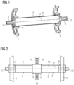
- FIG. 1 Illustrated side view of a first exemplary embodiment variant of a wheelset according to the invention for a chassis of a rail vehicle in a sectional view includes a first wheel 1 and a second wheel 2, which are connected to one another via a wheelset shaft 3.
- the wheelset has a wheelset longitudinal axis 17.
- the wheelset shaft 3 includes a first segment 4, a second segment 5 and a third segment 6.
- the second segment 5 is friction welded to the first segment 4 and the third segment 6.
- Corresponding friction welding processes are carried out as friction stir welding processes known from the prior art.
- a blank of the second segment 5 is connected to a blank of the first segment 4 and a blank of the third segment 6 without external heat input.
- the first segment 4 and the second segment 5 are guided together.
- a rotating tool presses with high contact pressure on the joint between the first segment 4 and the second segment 5. This creates friction and contact zones between the first segment 4 and the second segment 5 are heated and plasticized. This creates a mixing of materials and a secure connection between the first segment 4 and the second segment 5.
- the second segment 5 welded to the first segment 4 is then friction-welded to the third segment 6 in the same way as with respect to the first segment 4.
- the second segment 5 to the first segment 4 and the third segment 6 by means of a flash butt welding method known from the prior art.
- Welding heat is generated by electrical current.
- the blank of the first segment 4 is in point contact with the blank of the second segment 5, whereby liquid contact zones are formed between the first segment 4 and the second segment 5 due to a high current density.
- the electrical current flow is interrupted and the first segment 4 is pressed against the second segment 5, whereby a firm connection is created between the first segment 4 and the second segment 5.
- the second segment 5 welded to the first segment 4 is then flash-butt-welded to the third segment 6 in the same way as with respect to the first segment 4.
- the first wheel 1 and the second wheel 2 are pressed onto the wheelset shaft 3.
- the first wheel 1 is arranged in a transition area between the first segment 4 and the second segment 5, the second wheel 2 in a transition area between the second segment 5 and the third segment 6.
- the first wheel 1 covers a first weld seam, not shown second wheel 2 has a second weld seam, also not shown. This means that the first weld seam and the second weld seam are protected from environmental influences.
- the second segment 5 is designed as a thin-walled tube, which is manufactured using an extrusion process known from the prior art.
- the first segment 4 and the third segment 6 are designed as forged edge segments with a hollow bore or as hollow shafts.
- the first segment 4 points at its in Fig. 1
- the end shown on the left has a smaller outer diameter than at its in Fig. 1 end shown on the right.
- the third segment 6 points at its in Fig. 1
- the end shown on the right has a smaller outer diameter than at its in Fig. 1 end shown on the left.
- the wheelset shaft 3 has a mass that is approximately 50% lower than a solid shaft (solid, one-piece component) with the same outer contour.
- the first segment 4, the second segment 5 and the third segment 6 have a common first interior space 9 which is filled with compressed air.
- This first interior space 9 can be filled with compressed air and vented via a first opening 11 of the first segment 4 and a second opening 12 of the third segment 6. Valves (not shown) are provided in areas of the first opening 11 and the second opening 12.
- the valves have standardized adapters that can be used to connect pressure measuring devices (e.g. pressure gauges) and pressure supply devices (e.g. compressors or pumps).
- pressure measuring devices e.g. pressure gauges
- pressure supply devices e.g. compressors or pumps
- air pressures can be measured when the rail vehicle is at a standstill (e.g. during a maintenance process) and compared with a pressure limit. If the measured air pressure is lower than the pressure limit, this indicates damage to the wheelset shaft 3. This will then be repaired or replaced.
- the air pressure of the first interior 9 is increased to a target compressed air level.
- pressure sensors are provided in areas of the first opening 11 and the second opening 12. These pressure sensors are used to detect air pressures in the first interior 9 and, if necessary, pressure drops even while the rail vehicle is traveling. A pressure drop in the first interior 9 during operation of the rail vehicle indicates damage (e.g. a tear) to the wheelset shaft 3.
- the pressure sensors have radio interfaces as means for data transmission, via which pressure measurement result data relating to the first interior 9 is sent to a maintenance stand be transmitted.
- warning events can be triggered based on the transmitted pressure measurement result data. For example, if the pressure falls below the predefined limit value, this indicates damage to the wheelset shaft 3 (e.g. a tear) and necessary maintenance operations (e.g. replacing the wheelset shaft 3) are planned in the maintenance status.
- the pressure sensors are connected to a driver's cab of the rail vehicle by means of the radio interface, whereby warning events can also be triggered in the driver's cab based on pressure measurement result data transmitted to the driver's cab, i.e. if damage to the wheelset shaft 3 is detected, a corresponding warning is shown on a display.
- Fig. 2 shows a top view of a second exemplary embodiment variant of a wheelset according to the invention for a chassis of a rail vehicle.
- the wheelset has a wheelset longitudinal axis 17 and includes a first wheel 1 and a second wheel 2, which are pressed onto a wheelset shaft 3.
- the wheelset shaft 3 has a first segment 4, a second segment 5, a third segment 6, a fourth segment 7 and a fifth segment 8, which, as in connection with Fig. 1 described, are friction welded together.
- the first segment 4 and the fifth segment 8 each include a hollow bore.
- the first segment 4 has a first opening 11, the fifth segment 8 has a second opening 12.
- a first valve, not shown, and a first pressure sensor, also not shown are arranged in the area of the second opening 12 a second valve, not shown, and a second pressure sensor, also not shown, are arranged.
- the second segment 5 and the fourth segment 7 are designed as thin-walled tubes.
- the first segment 4 and the second segment 5 form a first interior space 9
- the fourth segment 7 and the fifth segment 8 form a second interior space 10.
- the first interior 9 and the second interior 10 are filled with compressed air, which, when the first segment 4 and the second segment 5 or the fourth segment 7 and the fifth segment 8 are undamaged, only escape via the first valve or the second valve can.
- the first pressure sensor measures pressures in the first interior 9
- the second pressure sensor measures pressures in the second interior 10.
- the first pressure sensor and the second pressure sensor have means for data transmission, whereby result data relating to measured pressures are transmitted to a maintenance stand for evaluation. If the evaluation shows that a predefined pressure limit value has been exceeded, damage (e.g. a tear) to the wheelset shaft 3 is assumed.
- pressure measurement result data is transmitted via the means for data transmission to a computing unit, not shown, which is arranged in the chassis or a car body of the rail vehicle.
- the pressure measurement result data is evaluated in the computing unit. If it is determined that the pressure limit is undershot, a warning event is triggered via data lines (not shown) between the computing unit and a driver's cab of the rail vehicle is triggered in the driver's cab and warnings are shown to a driver on a display.
- the means for data transmission have a cable interface or sockets, whereby cables or data plugs can be connected when the rail vehicle is at a standstill in order to read out pressure measurement result data and evaluate them on a computing station.
- first pressure sensor and the second pressure sensors can have memory modules. This means that pressure measurement result data can be saved and sent for a time-delayed evaluation.
- the third segment 6 is arranged between the second segment 5 and the fourth segment 7 of the wheelset shaft 3. It is designed as a forged part and friction welded to the second segment 5 and the fourth segment 7.
- the third segment 6 is designed as a wheel set component or as a brake disc 13, i.e. a cylindrical area, which is connected to the second segment 5 and to the fourth segment 7, merges seamlessly into an area designed as a wave brake disc.
- the shaft brake disc has a first friction ring 14 and a second friction ring 15.
- a heat sink 16 with cooling rods and cooling channels is formed between the first friction ring 14 and the second friction ring 15.
- the wheelset shaft 3 has more than five segments.
- the segments can be connected to one another in any sequence, for example in the form of tubes or forged parts.
- a forged sixth segment not shown, which is designed as a gear wheel of a transmission can be connected to the third segment 6.
- the sixth segment has a cylindrical area that merges seamlessly into a ring gear of the gear.
- segments designed as wheel set components are designed, for example, as hubs to which first friction rings 14 and second friction rings 15 of brake disks 13 are connected.
- segments designed as wheel set components are designed as wheel bodies, disc wheels, etc., which means that there is no need to press the first wheel 1 and the second wheel 2 onto the wheelset shaft 3.
Landscapes
- Engineering & Computer Science (AREA)
- Mechanical Engineering (AREA)
- Pressure Welding/Diffusion-Bonding (AREA)
- Measuring Fluid Pressure (AREA)
Description
- Die Erfindung betrifft einen Radsatz für Fahrzeuge, insbesondere für Fahrwerke von Schienenfahrzeugen, der ein erstes Rad, ein zweites Rad sowie eine Radsatzwelle aufweist, wobei die Radsatzwelle zumindest ein erstes Segment, ein zweites Segment und ein drittes Segment umfasst, wobei zumindest das zweite Segment mit dem ersten Segment und mit dem dritten Segment stoffschlüssig verbunden ist, und wobei von dem ersten Segment, dem zweiten Segment und dem dritten Segment zumindest ein Segment als Hohlwelle und mit Fluid befüllbar ausgebildet ist.
- Radsatzwellen müssen Kräfte zwischen Rädern übertragen und eine Anordnung von Radsatzkomponenten, z.B. Antriebs- und Bremskomponenten etc. auf dem Radsatz ermöglichen. Weiterhin sind eine hohe Bauteil- und Betriebssicherheit, eine geringe Masse, eine hohe Lebensdauer sowie geringe Kosten Auslegungsziele.
- Beispielsweise beschreibt die Europäische Norm (EN) 13261 Anforderungen und Prüfverfahren für Radsatzwellen im Hinblick auf Materialien (chemische Zusammensetzung) und mechanische Eigenschaften.
- Die
EP 2 069 180 B1 beschreibt eine zwei- bzw. dreiteilige Radsatzwelle für eine achsreitende elektrische Antriebsmaschine. Ein Blechpaket eines Läufers der Maschine ist auf einer Außenmantelfläche eines Mittelsegments Radsatzwelle angeordnet. Das Mittelsegment ist als Hohlwelle ausgebildet. Mit dem Mittelsegment sind ein erstes Randsegment sowie ein zweites Randsegment verbunden. Auf dem ersten Randsegment und dem zweiten Randsegment sind Räder angeordnet. Das erste Randsegment und das zweite Randsegment umfassen Längsbohrungen für eine Ultraschallprüfung der Radsatzwelle. Durchmesser der Längsbohrungen sind geringer als Innendurchmesser des hohlen Mittelsegments. - Einzelne Segmente der Radsatzwelle sind mittels einer Reibschweißtechnik fest verbunden.
- Weiterhin ist in der
RU 2 255 014 C1 - Darüber hinaus beschreibt die
JP 2011-46243 A - Die
DE 876 697 C zeigt eine Hohlwelle, insbesondere für Schienenfahrzeuge, welche verschiedene Segmente umfasst. Diese Segmente weisen Hohlräume unterschiedlicher Geometrien auf. In Übergangsbereichen zwischen Segmenten sind Sitze für Radnaben vorgesehen. Schweißnähte zur Verbindung der Segmente sind mittig auf den Sitzen vorgesehen. - Die
DE 10 2006 047 186 A1 offenbart eine Radsatzwelle, welche ein Hohlsegment aufweist, auf der ein Antriebsmotor angeordnet ist. Weiterhin sind Randsegmente vorgesehen, mit welchen Räder verbunden sein können. - In der
DE 195 06 678 A1 ist ein Radsatz für Schienenfahrzeuge dargestellt, welcher Achsstummeln und ein Zwischenrohr aufweist. Räder sind zwischen den Achsstummeln und dem Zwischenrohr angeordnet und mittels Zugankern verspannt. Mit dem Zwischenrohr sind weiterhin Bremsscheiben verbunden. - Die
DE 639 418 C zeigt weiterhin einen nabenlosen Radsatz, bei welchem ein hohler Achsschenkel unmittelbar in eine Stirnwand und eine Rückwand eines Radstegs übergeht und mit dem Radsteg, diesen nach außen hin abschließend, ein Radkranz verbunden ist. - Ferner ist in der
DE 850 758 C ein Radsatz für Schienenfahrzeuge mit einer Hohlachse gezeigt, welche im Bereich ihrer Enden trompetenartig gekrümmt ausgeführt ist, wobei aus dieser trompetenartigen Krümmung ein Grundkörper eines Rads gebildet wird. Eine Oberseite dieses Grundkörpers ist mit einer Unterseite eines Radstegs verschweißt. - Die
GB 2 073 118 A - In der
DE 864 408 C ist ein Herstellverfahren für Hohlachsen von Schienenfahrzeugen offenbart, bei welchem drei röhrenförmige Achssegmente miteinander verbunden sind. Ein Nabensitz auf einem Mittensegment wird mittels Aufstauchen und Aufdornen dieses Mittensegments erzeugt. Randsegmente werden mittels elektrischer Stumpfschweißung mit dem Mittensegment verbunden. - Darüber hinaus zeigt die
GB 746,197 A - Weiterhin offenbart die
DE 10 2009 033 353 A1 einen Radsatz für Schienenfahrzeuge mit einer Radsatz-Hohlwelle und zwei Rädern. Die Radsatz-Hohlwelle weist eine Längsbohrung mit einer Stützschraube auf. An die Längsbohrung kann zur Risskontrolle der Radsatz-Hohlwelle ein pneumatisches Druckbeaufschlagungsmittel angeschlossen werden. - Ferner sind aus dem Stand der Technik Radsatzwellen aus geschmiedeten Rohlingen bekannt, die Hohlbohrungen aufweisen. Bei einer Ausführung von Hohlbohrungen in Radsatzwellen ergeben sich jedoch insbesondere bei großen Wellendurchmessern hohe Materialverluste.
- Der Erfindung liegt die Aufgabe zugrunde, einen gegenüber dem Stand der Technik weiterentwickelten Radsatz anzugeben.
- Erfindungsgemäß wird diese Aufgabe gelöst mit einem Radsatz der eingangs genannten Art, bei dem zumindest eine erste Öffnung mit zumindest einem Ventil sowie zumindest ein Drucksensor vorgesehen sind.
- Dadurch wird eine modulare und belastungsgerechte Ausführung der Radsatzwelle erzielt. Beispielsweise kann das zweite Segment aus einem anderen Werkstoff als das erste Segment und das dritte Segment gefertigt sein, eine unterschiedliche Geometrie oder unterschiedliche Dimensionen aufweisen.
- Es werden eine Erkennung von Schäden (z.B. Durchrissen) der Radsatzwelle ermöglicht und somit eine erhöhte Betriebssicherheit sowie Vorteile in der Wartung und Instandhaltung erzielt.
- Es ist günstig, wenn das erste Rad auf dem ersten Segment sowie auf dem zweiten Segment, das erste Segment und das zweite Segment überlappend, angeordnet ist und das zweite Rad auf dem zweiten Segment sowie auf dem dritten Segment, das zweite Segment und das dritte Segment überlappend, angeordnet ist.
- Durch eine Anordnung des ersten Rads in einem ersten Übergangsbereich zwischen dem ersten Segment und dem zweiten Segment und des zweiten Rads in einem zweiten Übergangsbereich zwischen dem zweiten Segment und dem dritten Segment wird eine vorteilhafte Überdeckung des ersten Übergangsbereichs und des zweiten Übergangsbereichs erzielt. Der erste Übergangsbereich und der zweite Übergangsbereich sind vor Umgebungseinflüssen und Korrosion etc. geschützt.
- Eine vorteilhafte Ausgestaltung erhält man, wenn von dem ersten Segment, dem zweiten Segment und dem dritten Segment zumindest ein Segment als dünnwandiges Rohr ausgeführt ist. Durch diese Maßnahme werden Widerstandsmomente der Radsatzwelle gegen Torsion erhöht und ein sparsamer Materialeinsatz bewirkt. Bei gleichem Werkstoffeinsatz können für die Hohlwelle im Vergleich zu einer Vollwelle eine Erhöhung der Festigkeit und somit der Bauteilsicherheit sowie eine Reduktion der Masse erzielt werden.
- Eine vorteilhafte Lösung wird erzielt, wenn der zumindest eine Drucksensor Mittel zur Datenübertragung aufweist.
- Die Mittel zur Datenübertragung können beispielsweise eine Funkschnittstelle aufweisen. Durch diese Maßnahme können Informationen, welche einen Schaden der Radsatzwelle anzeigen, rasch an einen Wartungsstand übermittelt werden.
- Eine günstige Lösung erhält man, wenn von dem ersten Segment, dem zweiten Segment und dem dritten Segment zumindest ein Segment als Vollwelle ausgeführt ist.
- Durch diese Maßnahme werden eine hohe Flexibilität und eine belastungsgerechte Ausführung der Radsatzwelle erzielt. Beispielsweise können das zweite Segment als Hohlwelle und das erste Segment sowie das dritte Segment als Vollwelle ausgeführt sein. Fügestellen des ersten Segments und des dritten Segments zu Komponenten wie Radsatzlagern können dadurch entlastet werden.
- Es ist günstig, wenn zumindest das zweite Segment mit dem ersten Segment und mit dem dritten Segment reibverschweißt ist.
- Durch diese Maßnahme können für das erste Segment, das zweite Segment und das dritte Segment unterschiedliche Werkstoffe eingesetzt werden. Weiterhin bewirken Reibschweißvorgänge kleine Wärmeeinflusszonen in Kontaktbereichen zwischen dem zweiten Segment und dem ersten Segment sowie dem zweiten Segment und dem dritten Segment. Dadurch werden nachteilige Veränderungen von mechanischen Eigenschaften der Radsatzwelle aufgrund der Reibschweißvorgänge vermieden.
- Eine vorteilhafte Ausgestaltung erhält man, wenn zumindest das zweite Segment mit dem ersten Segment und mit dem dritten Segment abbrennstumpfverschweißt ist.
- Durch diese Maßnahme werden Verunreinigungen von Schweißstellen vermieden und es wird eine Schutzgasatmosphäre in Bereichen der Schweißstellen erzeugt, welche die Schweißstellen schützen.
- Nachfolgend wird die Erfindung anhand von Ausführungsbeispielen näher erläutert.
- Es zeigen beispielhaft:
- Fig. 1:
- Einen Seitenriss einer ersten beispielhaften Ausführungsvariante eines erfindungsgemäßen Radsatzes mit einem ersten Segment, einem zweiten Segment und einem dritten Segment in geschnittener Darstellung, und
- Fig. 2:
- Einen Seitenriss einer zweiten beispielhaften Ausführungsvariante eines erfindungsgemäßen Radsatzes mit einem ersten Segment, einem zweiten Segment, einem dritten Segment, einem vierten Segment und einem fünften Segment.
- Ein in
Fig. 1 dargestellter Seitenriss einer ersten beispielhaften Ausführungsvariante eines erfindungsgemäßen Radsatzes für ein Fahrwerk eines Schienenfahrzeugs in Schnittdarstellung umfasst ein erstes Rad 1 und ein zweites Rad 2, die über eine Radsatzwelle 3 miteinander verbunden sind. - Der Radsatz weist eine Radsatzlängsachse 17 auf. Die Radsatzwelle 3 umfasst ein erstes Segment 4, ein zweites Segment 5 und ein drittes Segment 6. Das zweite Segment 5 ist mit dem ersten Segment 4 und dem dritten Segment 6 reibverschweißt. Entsprechende Reibschweißvorgänge sind als aus dem Stand der Technik bekannte Rührreibschweißvorgänge ausgeführt. Es wird dabei ein Rohling des zweiten Segments 5 mit einem Rohling des ersten Segments 4 und einem Rohling des dritten Segments 6 ohne äußere Wärmeeinbringung verbunden. Das erste Segment 4 und das zweite Segment 5 werden aneinander geführt. Ein rotierendes Werkzeug drückt mit hoher Anpresskraft auf die Trennfuge zwischen dem ersten Segment 4 und dem zweiten Segment 5. Dadurch entsteht Reibung und Kontaktzonen zwischen dem ersten Segment 4 und dem zweiten Segment 5 werden erwärmt und plastifiziert. Dadurch werden eine Materialvermischung sowie eine sichere Verbindung zwischen dem ersten Segment 4 und dem zweiten Segment 5 erzeugt. Anschließend wird das mit dem ersten Segment 4 verschweißte zweite Segment 5 in gleicher Weise wie bezüglich des ersten Segments 4 mit dem dritten Segment 6 reibverschweißt.
- Erfindungsgemäß ist es auch möglich, das zweite Segment 5 mit dem ersten Segment 4 und dem dritten Segment 6 mittels eines aus dem Stand der Technik bekannten Abbrennstumpfschweißverfahrens zu verbinden. Dabei wird Schweißwärme durch elektrischen Strom erzeugt. Der Rohling des ersten Segments 4 ist mit dem Rohling des zweiten Segments 5 punktuell in Kontakt, wodurch aufgrund einer hohen Stromdichte flüssige Kontaktzonen zwischen dem ersten Segment 4 und dem zweiten Segment 5 ausgebildet werden. Bei Erreichen einer erforderlichen Temperatur in den Kontaktzonen wird der elektrische Stromfluss unterbrochen und das erste Segment 4 an das zweite Segment 5 gepresst, wodurch zwischen dem ersten Segment 4 und dem zweiten Segment 5 eine feste Verbindung erzeugt wird. Anschließend wird das mit dem ersten Segment 4 verschweißte zweite Segment 5 in gleicher Weise wie bezüglich des ersten Segments 4 mit dem dritten Segment 6 abbrennstumpfverschweißt.
- Aufgrund von Abbrennstumpfschweißvorgängen an Schweißnähten erzeugte Grate werden mittels Schleifvorgängen entfernt.
- Das erste Rad 1 und das zweite Rad 2 sind auf die Radsatzwelle 3 aufgepresst. Das erste Rad 1 ist in einem Übergangsbereich zwischen dem ersten Segment 4 und dem zweiten Segment 5 angeordnet, das zweite Rad 2 in einem Übergangsbereich zwischen dem zweiten Segment 5 und dem dritten Segment 6. Das erste Rad 1 überdeckt eine nicht dargestellte erste Schweißnaht, das zweite Rad 2 eine ebenfalls nicht dargestellte zweite Schweißnaht. Dadurch sind die erste Schweißnaht und die zweite Schweißnaht vor Umgebungseinflüssen geschützt.
- Das zweite Segment 5 ist als dünnwandiges Rohr ausgeführt, das mittels eines aus dem Stand der Technik bekannten Strangpressverfahrens gefertigt wird. Das erste Segment 4 und das dritte Segment 6 sind als geschmiedete Randsegmente mit einer Hohlbohrung bzw. als Hohlwellen ausgeführt. Das erste Segment 4 weist an seinem in
Fig. 1 links dargestellten Ende einen kleineren Außendurchmesser auf als an seinem inFig. 1 rechts gezeigten Ende. - Das dritte Segment 6 weist an seinem in
Fig. 1 rechts dargestellten Ende einen kleineren Außendurchmesser auf als an seinem inFig. 1 links gezeigten Ende. - In Bereichen dieser kleineren Durchmesser sind nicht dargestellte Radsatzlager auf die Radsatzwelle 3 aufgepresst. Die Radsatzwelle 3 weist gegenüber einer Vollwelle (massives, einstückiges Bauteil) mit gleicher Außenkontur eine um ca. 50% geringere Masse auf.
- Das erste Segment 4, das zweite Segment 5 und das dritte Segment 6 weisen einen gemeinsamen ersten Innenraum 9 auf, der mit Druckluft gefüllt ist.
- Über eine erste Öffnung 11 des ersten Segments 4 und eine zweite Öffnung 12 des dritten Segments 6 ist dieser erste Innenraum 9 mit Druckluft befüllbar und entlüftbar. In Bereichen der ersten Öffnung 11 und der zweiten Öffnung 12 sind dazu nicht dargestellte Ventile vorgesehen.
- Die Ventile weisen standardisierte Adapter auf, mittels derer Druckmessgeräte (z.B. Manometer) und Druckversorgungsgeräte (z.B. Kompressoren oder Pumpen) anschließbar sind.
- Mittels eines Druckmessgeräts können Luftdrücke im Stillstand des Schienenfahrzeugs gemessen (z.B. während eines Instandhaltungsvorgangs) und mit einem Druckgrenzwert verglichen werden. Ist der gemessene Luftdruck geringer als der Druckgrenzwert, so weist dies auf einen Schaden der Radsatzwelle 3 hin. Diese wird daraufhin repariert oder getauscht.
- Mittels eines Druckversorgungsgeräts wird der Luftdruck des ersten Innenraums 9 auf ein Soll-Druckluftniveau gesteigert.
- Weiterhin sind in Bereichen der ersten Öffnung 11 und der zweiten Öffnung 12 nicht dargestellte Drucksensoren vorgesehen. Mittels dieser Drucksensoren werden Luftdrücke in dem ersten Innenraum 9 und gegebenenfalls Druckabfälle auch während einer Fahrt des Schienenfahrzeugs erkannt. Ein Druckabfall in dem ersten Innenraum 9 im Betrieb des Schienenfahrzeugs zeigt einen Schaden (z.B. einen Durchriss) der Radsatzwelle 3 an.
- Die Drucksensoren weisen als Mittel zur Datenübertragung Funkschnittstellen auf, über die Druckmessergebnisdaten betreffend den ersten Innenraum 9 an einen Wartungsstand übertragen werden. In dem Wartungsstand können auf Grundlage der übertragenen Druckmessergebnisdaten Warnereignisse ausgelöst werden. Wird beispielsweise der vordefinierte Druckgrenzwert unterschritten, so weist dies auf einen Schaden der Radsatzwelle 3 (z.B. einen Durchriss) hin und es werden in dem Wartungsstand erforderliche Wartungsvorgänge (z.B. ein Tausch der Radsatzwelle 3) geplant.
- Weiterhin sind die Drucksensoren mittels der Funkschnittstelle mit einem Führerstand des Schienenfahrzeugs verbunden, wodurch auf Grundlage von in den Führerstand übertragenen Druckmessergebnisdaten auch in dem Führerstand Warnereignisse ausgelöst werden können, d.h. bei Detektion eines Schadens der Radsatzwelle 3 auf einer Anzeige ein entsprechender Warnhinweis dargestellt wird.
- Erfindungsgemäß ist es auch denkbar, ein anderes Fluid als Druckluft, beispielsweise eine Hydraulikflüssigkeit, für eine Befüllung des ersten Innenraums 9 vorzusehen.
-
Fig. 2 zeigt eine Draufsicht auf eine zweite beispielhafte Ausführungsvariante eines erfindungsgemäßen Radsatzes für ein Fahrwerk eines Schienenfahrzeugs. - Der Radsatz weist eine Radsatzlängsachse 17 auf und umfasst ein erstes Rad 1 und ein zweites Rad 2, die auf eine Radsatzwelle 3 aufgepresst sind.
- Die Radsatzwelle 3 weist ein erstes Segment 4, ein zweites Segment 5, ein drittes Segment 6, ein viertes Segment 7 sowie ein fünftes Segment 8 auf, die, wie in Zusammenhang mit
Fig. 1 beschrieben, miteinander reibverschweißt sind. Das erste Segment 4 und das fünfte Segment 8 umfassen je eine Hohlbohrung. Das erste Segment 4 weist eine erste Öffnung 11 auf, das fünfte Segment 8 eine zweite Öffnung 12. Im Bereich der ersten Öffnung 11 sind ein nicht gezeigtes erstes Ventil sowie ein ebenfalls nicht dargestellter erster Drucksensor angeordnet. Im Bereich der zweiten Öffnung 12 sind ein nicht dargestelltes zweites Ventil sowie ein ebenfalls nicht gezeigter zweiter Drucksensor angeordnet. - Das zweite Segment 5 und das vierte Segment 7 sind als dünnwandige Rohre ausgeführt. Das erste Segment 4 und das zweite Segment 5 bilden einen ersten Innenraum 9, das vierte Segment 7 und das fünfte Segment 8 einen zweiten Innenraum 10.
- Der erste Innenraum 9 und der zweite Innenraum 10 sind mit Druckluft gefüllt, die in einem unbeschädigten Zustand des ersten Segments 4 und des zweiten Segments 5 bzw. des vierten Segments 7 und des fünften Segments 8 nur über das erste Ventil bzw. das zweite Ventil entweichen kann.
- Der erste Drucksensor misst Drücke in dem ersten Innenraum 9, der zweite Drucksensor Drücke in dem zweiten Innenraum 10. Der erste Drucksensor und der zweite Drucksensor weisen Mittel zur Datenübertragung auf, wodurch Ergebnisdaten bezüglich gemessener Drücke zur Auswertung an einen Wartungsstand übertragen werden. Ergibt die Auswertung, dass ein vordefinierter Druckgrenzwert unterschritten ist, wird ein Schaden (z.B. ein Durchriss) an der Radsatzwelle 3 angenommen.
- Unterschreitet ein von dem ersten Drucksensor gemessener Druckwert den Druckgrenzwert, so wird angenommen, dass der Schaden im Bereich des ersten Segments 4 oder des zweiten Segments 5 aufgetreten ist.
- Unterschreitet ein von dem zweiten Drucksensor gemessener Druckwert den Druckgrenzwert, so wird angenommen, dass der Schaden im Bereich des vierten Segments 7 oder des fünften Segments 8 aufgetreten ist.
- Erfindungsgemäß ist es auch vorstellbar, dass über die Mittel zur Datenübertragung Druckmessergebnisdaten an eine nicht dargestellte Recheneinheit, die in dem Fahrwerk oder einem Wagenkasten des Schienenfahrzeugs angeordnet ist, übertragen werden. In der Recheneinheit werden die Druckmessergebnisdaten ausgewertet. Wird dabei eine Unterschreitung des Druckgrenzwerts festgestellt, wird über nicht dargestellte Datenleitungen zwischen der Recheneinheit und einem Führerstand des Schienenfahrzeugs ein Warnereignis in dem Führerstand ausgelöst und es werden einem Treibfahrzeugführer auf einer Anzeige Warnhinweise angezeigt.
- Erfindungsgemäß ist es weiterhin denkbar, dass die Mittel zur Datenübertragung eine Kabelschnittstelle bzw. Buchsen aufweisen, wodurch bei Stillstand des Schienenfahrzeugs Kabel bzw. Datenstecker angeschlossen werden können, um Druckmessergebnisdaten auszulesen und diese auf einer Rechenstation auszuwerten.
- Weiterhin ist es möglich, dass der erste Drucksensor und der zweite Drucksensoren Speichermodule aufweisen. Dadurch können Druckmessergebnisdaten gespeichert und einer zeitverzögerten Auswertung zugeführt werden.
- Zwischen dem zweiten Segment 5 und dem vierten Segment 7 der Radsatzwelle 3 ist das dritte Segment 6 angeordnet. Es ist als Schmiedeteil ausgeführt und mit dem zweiten Segment 5 und dem vierten Segment 7 reibverschweißt.
- Das dritte Segment 6 ist als Radsatzkomponente bzw. als Bremsscheibe 13 ausgebildet, d.h. ein zylindrischer Bereich, der mit dem zweiten Segment 5 und mit dem vierten Segment 7 verbunden ist, geht nahtlos in einen als Wellenbremsscheibe ausgebildeten Bereich über. Die Wellenbremsscheibe weist einen ersten Reibring 14 und einen zweiten Reibring 15 auf. Zwischen dem ersten Reibring 14 und dem zweiten Reibring 15 ist ein Kühlkörper 16 mit Kühlstäben und Kühlkanälen ausgebildet.
- Erfindungsgemäß ist es auch vorstellbar, dass die Radsatzwelle 3 mehr als fünf Segmente aufweist. Die Segmente können, beispielsweise als Rohre oder als Schmiedeteile ausgeführt, in beliebiger Abfolge miteinander verbunden sein. Beispielsweise kann mit dem dritten Segment 6 ein nicht gezeigtes, geschmiedetes sechstes Segment verbunden sein, welches als Zahnrad eines Getriebes ausgeführt ist. Das sechste Segment weist einen zylindrischen Bereich auf, der nahtlos in einen Zahnkranz des Zahnrads übergeht.
- Erfindungsgemäß ist es weiterhin möglich, dass als Radsatzkomponenten ausgebildete Segmente beispielsweise als Naben ausgeführt sind, mit denen erste Reibringe 14 und zweite Reibringe 15 von Bremsscheiben 13 verbunden sind. Darüber hinaus ist es auch denkbar, dass als Radsatzkomponenten ausgebildete Segmente als Radkörper, Scheibenräder etc. ausgeführt sind, wodurch auf ein Aufpressen des ersten Rads 1 und des zweiten Rads 2 auf die Radsatzwelle 3 verzichtet werden kann.
-
- 1
- Erstes Rad
- 2
- Zweites Rad
- 3
- Radsatzwelle
- 4
- Erstes Segment
- 5
- Zweites Segment
- 6
- Drittes Segment
- 7
- Viertes Segment
- 8
- Fünftes Segment
- 9
- Erster Innenraum
- 10
- Zweiter Innenraum
- 11
- Erste Öffnung
- 12
- Zweite Öffnung
- 13
- Bremsscheibe
- 14
- Erster Reibring
- 15
- Zweiter Reibring
- 16
- Kühlkörper
- 17
- Radsatzlängsachse
Claims (14)
- Radsatz für Fahrzeuge, insbesondere für Fahrwerke von Schienenfahrzeugen, der ein erstes Rad (1), ein zweites Rad (2) sowie eine Radsatzwelle (3) aufweist, wobei die Radsatzwelle (3) zumindest ein erstes Segment (4), ein zweites Segment (5) und ein drittes Segment (6) umfasst, wobei zumindest das zweite Segment (5) mit dem ersten Segment (4) und mit dem dritten Segment (6) stoffschlüssig verbunden ist, und wobei von dem ersten Segment (4), dem zweiten Segment (5) und dem dritten Segment (6) zumindest ein Segment als Hohlwelle und mit Fluid befüllbar ausgebildet ist, dadurch gekennzeichnet, dass zumindest eine erste Öffnung (11) mit zumindest einem Ventil sowie zumindest ein Drucksensor vorgesehen sind.
- Radsatz nach Anspruch 1, dadurch gekennzeichnet, dass das erste Rad (1) auf dem ersten Segment (4) sowie auf dem zweiten Segment (5), das erste Segment (4) und das zweite Segment (5) überlappend, angeordnet ist und das zweite Rad (2) auf dem zweiten Segment (5) sowie auf dem dritten Segment (6), das zweite Segment (5) und das dritte Segment (6) überlappend, angeordnet ist.
- Radsatz nach Anspruch 1 oder 2, dadurch gekennzeichnet, dass von dem ersten Segment (4), dem zweiten Segment (5) und dem dritten Segment (6) zumindest ein Segment als dünnwandiges Rohr ausgeführt ist.
- Radsatz nach einem der Ansprüche 1, 2 oder 3, dadurch gekennzeichnet, dass das zumindest eine, mit Fluid befüllbar ausgebildete Segment mit Druckluft befüllbar ausgeführt ist.
- Radsatz nach einem der Ansprüche 1, 2, 3 oder 4, dadurch gekennzeichnet, dass der zumindest eine Drucksensor Mittel zur Datenübertragung aufweist.
- Radsatz nach Anspruch 5, dadurch gekennzeichnet, dass die Mittel zur Datenübertragung zumindest eine Funkschnittstelle aufweisen.
- Radsatz nach einem der Ansprüche 1, 2, 3, 4, 5 oder 6, dadurch gekennzeichnet, dass an das zumindest eine Ventil Druckmessgeräte und Druckversorgungsgeräte anschließbar sind.
- Radsatz nach einem der Ansprüche 1, 2, 3, 4, 5, 6 oder 7, dadurch gekennzeichnet, dass von dem ersten Segment (4), dem zweiten Segment (5) und dem dritten Segment (6) zumindest ein Segment als Vollwelle ausgeführt ist.
- Radsatz nach einem der Ansprüche 1, 2, 3, 4, 5, 6, 7 oder 8, dadurch gekennzeichnet, dass zumindest das zweite Segment (5) mit dem ersten Segment (4) und mit dem dritten Segment (6) verschweißt ist.
- Radsatz nach Anspruch 9, dadurch gekennzeichnet, dass zumindest das zweite Segment (5) mit dem ersten Segment (4) und mit dem dritten Segment (6) reibverschweißt ist.
- Radsatz nach Anspruch 9, dadurch gekennzeichnet, dass zumindest das zweite Segment (5) mit dem ersten Segment (4) und mit dem dritten Segment (6) abbrennstumpfverschweißt ist.
- Radsatz nach einem der Ansprüche 1, 2, 3, 4, 5, 6, 7, 8, 9, 10 oder 11, dadurch gekennzeichnet, dass von dem ersten Segment (4), dem zweiten Segment (5) und dem dritten Segment (6) zumindest ein Segment als Radsatzkomponente ausgeführt ist.
- Radsatz nach Anspruch 12, dadurch gekennzeichnet, dass die Radsatzkomponente als Bremsscheibe (13) ausgeführt ist.
- Radsatz nach Anspruch 12, dadurch gekennzeichnet, dass die Radsatzkomponente als zumindest ein Zahnrad ausgeführt ist.
Applications Claiming Priority (2)
| Application Number | Priority Date | Filing Date | Title |
|---|---|---|---|
| ATA50536/2017A AT520102B1 (de) | 2017-06-29 | 2017-06-29 | Radsatz für Fahrzeuge |
| PCT/EP2018/067195 WO2019002343A1 (de) | 2017-06-29 | 2018-06-27 | Radsatz für fahrzeuge |
Publications (2)
| Publication Number | Publication Date |
|---|---|
| EP3600914A1 EP3600914A1 (de) | 2020-02-05 |
| EP3600914B1 true EP3600914B1 (de) | 2024-03-13 |
Family
ID=62874858
Family Applications (1)
| Application Number | Title | Priority Date | Filing Date |
|---|---|---|---|
| EP18739760.9A Active EP3600914B1 (de) | 2017-06-29 | 2018-06-27 | Radsatz für fahrzeuge |
Country Status (4)
| Country | Link |
|---|---|
| EP (1) | EP3600914B1 (de) |
| CN (1) | CN212386243U (de) |
| AT (1) | AT520102B1 (de) |
| WO (1) | WO2019002343A1 (de) |
Families Citing this family (2)
| Publication number | Priority date | Publication date | Assignee | Title |
|---|---|---|---|---|
| AT522189B1 (de) * | 2019-02-20 | 2020-12-15 | Siemens Mobility Austria Gmbh | Radsatz für Fahrzeuge |
| AT524098B1 (de) | 2020-07-28 | 2023-12-15 | Siemens Mobility Austria Gmbh | Fluidische Überwachungseinrichtung und fluidisches Überwachungsverfahren für Radsätze von Schienenfahrzeugen |
Family Cites Families (11)
| Publication number | Priority date | Publication date | Assignee | Title |
|---|---|---|---|---|
| DE639418C (de) * | 1933-11-29 | 1936-12-04 | Richard Hochheim | Nabenloser Radsatz fuer Schienenfahrzeuge mit Aussenlagern |
| CH260474A (de) * | 1946-07-04 | 1949-03-15 | Uno Leander Alf | Radsatz für Schienenfahrzeuge. |
| DE876697C (de) * | 1948-10-02 | 1953-05-18 | Walter Siepmann | Hohlachse bzw. -welle fuer Fahrzeuge, insbesondere fuer Schienen-fahrzeuge, und Verfahren zu ihrer Herstellung |
| DE864408C (de) * | 1949-10-25 | 1953-01-26 | Siepmann Werke Ag | Verfahren zur Herstellung einer Hohlachse fuer Fahrzeuge, insbesondere fuer Eisenbahnfahrzeuge |
| GB746197A (en) * | 1953-08-17 | 1956-03-14 | Kloeckner Georgsmarienwerke Ag | Improvements in or relating to vehicle wheels |
| US4307910A (en) * | 1980-04-04 | 1981-12-29 | Pullman Incorporated | Railway wheels and light weight axles |
| DE19506678A1 (de) * | 1995-02-25 | 1996-08-29 | Gutehoffnungshuette Radsatz | Radsatz für Schienenfahrzeuge |
| DE102006047186A1 (de) * | 2006-10-05 | 2008-04-10 | Siemens Ag | Radsatzwelle für eine achsreitende elektrische Antriebsmaschine und Antriebseinheit |
| DE102009033353B4 (de) * | 2008-08-05 | 2014-09-18 | Georg Rebel | Radsatz mit Scheibenrädern für Hochgeschwindigkeitszüge |
| JP5305399B2 (ja) * | 2009-08-26 | 2013-10-02 | 公益財団法人鉄道総合技術研究所 | 鉄道車両の組立台車枠及びその亀裂検出システム |
| EP2853879B1 (de) * | 2013-09-25 | 2020-04-01 | DMA S.r.l. | Einrichtung für die Untersuchung von Eisenbahnachsen |
-
2017
- 2017-06-29 AT ATA50536/2017A patent/AT520102B1/de not_active IP Right Cessation
-
2018
- 2018-06-27 CN CN201890000977.5U patent/CN212386243U/zh active Active
- 2018-06-27 EP EP18739760.9A patent/EP3600914B1/de active Active
- 2018-06-27 WO PCT/EP2018/067195 patent/WO2019002343A1/de not_active Ceased
Also Published As
| Publication number | Publication date |
|---|---|
| AT520102A1 (de) | 2019-01-15 |
| EP3600914A1 (de) | 2020-02-05 |
| CN212386243U (zh) | 2021-01-22 |
| WO2019002343A1 (de) | 2019-01-03 |
| AT520102B1 (de) | 2019-03-15 |
Similar Documents
| Publication | Publication Date | Title |
|---|---|---|
| EP1036680B1 (de) | Verbundlenkerachse für Kraftfahrzeuge | |
| EP2736733B1 (de) | Fahrwerksystem für nutzfahrzeuge | |
| EP3911524B1 (de) | Radsatz für fahrzeuge | |
| EP1318035B1 (de) | Verfahren zur Herstellung eines Lenkers und Lenker | |
| EP3281837A1 (de) | Fahrwerksrahmen eines schienenfahrzeugs | |
| DE102010022621A1 (de) | Rotorwelle für ein elektrisches Aggregat | |
| EP3600914B1 (de) | Radsatz für fahrzeuge | |
| DE102009039479A1 (de) | Stabilisatoranordnung | |
| DE102014218332B4 (de) | Achseinheit | |
| EP3191315B1 (de) | Achseinheit | |
| DE102016121756B3 (de) | Karosserieanbindung eines Achshilfsrahmens sowie Verfahren zur Herstellung der Karosserieanbindung | |
| DE102012004389B4 (de) | Ausgleichsgetriebe für einen Kraftwagen als Schweißkonstruktion mit unterschiedlichen Werkstoffen | |
| DE102016013493B4 (de) | Antriebswellenbaugruppe und Verfahren für ihre Herstellung | |
| DE4208014C2 (de) | Straßensimulationsprüfstand für Fahrzeugachsen | |
| DE102013207699B4 (de) | Werkzeugsatz zur Reparatur einer Fahrzeugachse | |
| EP2604455A1 (de) | Stabilisatoranordnung für ein Kraftfahrzeug und Verfahren zur Herstellung eines Stabilisatorabschnitts | |
| DE102010038260A1 (de) | Verfahren zum Herstellen einer Verbundlenkerachse in Mischbauweise | |
| DE102004012667A1 (de) | Rad, Radkörper und Radsatz eines Schienenfahrzeuges | |
| DE102021201719A1 (de) | Lasteinleitungselement für ein Fahrwerkbauteil, Verfahren zum Herstellen eines Lasteinleitungselementes sowie Fahrwerkbauteil | |
| DE102020128306A1 (de) | Planetenträger-Baugruppe, Verfahren zur Herstellung einer Planetenträger-Baugruppe und Planetengetriebe | |
| EP3699442A1 (de) | Hohlwellenelement mit durchmesseraufweitung | |
| DE202016006444U1 (de) | Messsonde zur Unterbringung in der Hohlwelle eines Radsatzes von einem Schienenfahrzeug zum Zweck von Schwingungsmessungen | |
| DE2450780A1 (de) | Vorrichtung zum messen von kraeften an flugzeugen | |
| DE102016218431A1 (de) | Verfahren zum Reparieren fehlerhafter Verbindungen | |
| DE102011008582A1 (de) | Torsionsmodul |
Legal Events
| Date | Code | Title | Description |
|---|---|---|---|
| STAA | Information on the status of an ep patent application or granted ep patent |
Free format text: STATUS: UNKNOWN |
|
| STAA | Information on the status of an ep patent application or granted ep patent |
Free format text: STATUS: THE INTERNATIONAL PUBLICATION HAS BEEN MADE |
|
| PUAI | Public reference made under article 153(3) epc to a published international application that has entered the european phase |
Free format text: ORIGINAL CODE: 0009012 |
|
| STAA | Information on the status of an ep patent application or granted ep patent |
Free format text: STATUS: REQUEST FOR EXAMINATION WAS MADE |
|
| 17P | Request for examination filed |
Effective date: 20191024 |
|
| AK | Designated contracting states |
Kind code of ref document: A1 Designated state(s): AL AT BE BG CH CY CZ DE DK EE ES FI FR GB GR HR HU IE IS IT LI LT LU LV MC MK MT NL NO PL PT RO RS SE SI SK SM TR |
|
| AX | Request for extension of the european patent |
Extension state: BA ME |
|
| DAV | Request for validation of the european patent (deleted) | ||
| DAX | Request for extension of the european patent (deleted) | ||
| STAA | Information on the status of an ep patent application or granted ep patent |
Free format text: STATUS: EXAMINATION IS IN PROGRESS |
|
| 17Q | First examination report despatched |
Effective date: 20220721 |
|
| GRAP | Despatch of communication of intention to grant a patent |
Free format text: ORIGINAL CODE: EPIDOSNIGR1 |
|
| STAA | Information on the status of an ep patent application or granted ep patent |
Free format text: STATUS: GRANT OF PATENT IS INTENDED |
|
| INTG | Intention to grant announced |
Effective date: 20231024 |
|
| GRAS | Grant fee paid |
Free format text: ORIGINAL CODE: EPIDOSNIGR3 |
|
| GRAA | (expected) grant |
Free format text: ORIGINAL CODE: 0009210 |
|
| STAA | Information on the status of an ep patent application or granted ep patent |
Free format text: STATUS: THE PATENT HAS BEEN GRANTED |
|
| AK | Designated contracting states |
Kind code of ref document: B1 Designated state(s): AL AT BE BG CH CY CZ DE DK EE ES FI FR GB GR HR HU IE IS IT LI LT LU LV MC MK MT NL NO PL PT RO RS SE SI SK SM TR |
|
| REG | Reference to a national code |
Ref country code: GB Ref legal event code: FG4D Free format text: NOT ENGLISH |
|
| REG | Reference to a national code |
Ref country code: CH Ref legal event code: EP |
|
| REG | Reference to a national code |
Ref country code: DE Ref legal event code: R096 Ref document number: 502018014257 Country of ref document: DE |
|
| REG | Reference to a national code |
Ref country code: IE Ref legal event code: FG4D Free format text: LANGUAGE OF EP DOCUMENT: GERMAN |
|
| PG25 | Lapsed in a contracting state [announced via postgrant information from national office to epo] |
Ref country code: LT Free format text: LAPSE BECAUSE OF FAILURE TO SUBMIT A TRANSLATION OF THE DESCRIPTION OR TO PAY THE FEE WITHIN THE PRESCRIBED TIME-LIMIT Effective date: 20240313 |
|
| REG | Reference to a national code |
Ref country code: LT Ref legal event code: MG9D |
|
| PG25 | Lapsed in a contracting state [announced via postgrant information from national office to epo] |
Ref country code: GR Free format text: LAPSE BECAUSE OF FAILURE TO SUBMIT A TRANSLATION OF THE DESCRIPTION OR TO PAY THE FEE WITHIN THE PRESCRIBED TIME-LIMIT Effective date: 20240614 |
|
| REG | Reference to a national code |
Ref country code: NL Ref legal event code: MP Effective date: 20240313 |
|
| PG25 | Lapsed in a contracting state [announced via postgrant information from national office to epo] |
Ref country code: HR Free format text: LAPSE BECAUSE OF FAILURE TO SUBMIT A TRANSLATION OF THE DESCRIPTION OR TO PAY THE FEE WITHIN THE PRESCRIBED TIME-LIMIT Effective date: 20240313 Ref country code: RS Free format text: LAPSE BECAUSE OF FAILURE TO SUBMIT A TRANSLATION OF THE DESCRIPTION OR TO PAY THE FEE WITHIN THE PRESCRIBED TIME-LIMIT Effective date: 20240613 |
|
| PG25 | Lapsed in a contracting state [announced via postgrant information from national office to epo] |
Ref country code: ES Free format text: LAPSE BECAUSE OF FAILURE TO SUBMIT A TRANSLATION OF THE DESCRIPTION OR TO PAY THE FEE WITHIN THE PRESCRIBED TIME-LIMIT Effective date: 20240313 |
|
| PG25 | Lapsed in a contracting state [announced via postgrant information from national office to epo] |
Ref country code: RS Free format text: LAPSE BECAUSE OF FAILURE TO SUBMIT A TRANSLATION OF THE DESCRIPTION OR TO PAY THE FEE WITHIN THE PRESCRIBED TIME-LIMIT Effective date: 20240613 Ref country code: NO Free format text: LAPSE BECAUSE OF FAILURE TO SUBMIT A TRANSLATION OF THE DESCRIPTION OR TO PAY THE FEE WITHIN THE PRESCRIBED TIME-LIMIT Effective date: 20240613 Ref country code: LT Free format text: LAPSE BECAUSE OF FAILURE TO SUBMIT A TRANSLATION OF THE DESCRIPTION OR TO PAY THE FEE WITHIN THE PRESCRIBED TIME-LIMIT Effective date: 20240313 Ref country code: HR Free format text: LAPSE BECAUSE OF FAILURE TO SUBMIT A TRANSLATION OF THE DESCRIPTION OR TO PAY THE FEE WITHIN THE PRESCRIBED TIME-LIMIT Effective date: 20240313 Ref country code: GR Free format text: LAPSE BECAUSE OF FAILURE TO SUBMIT A TRANSLATION OF THE DESCRIPTION OR TO PAY THE FEE WITHIN THE PRESCRIBED TIME-LIMIT Effective date: 20240614 Ref country code: FI Free format text: LAPSE BECAUSE OF FAILURE TO SUBMIT A TRANSLATION OF THE DESCRIPTION OR TO PAY THE FEE WITHIN THE PRESCRIBED TIME-LIMIT Effective date: 20240313 Ref country code: ES Free format text: LAPSE BECAUSE OF FAILURE TO SUBMIT A TRANSLATION OF THE DESCRIPTION OR TO PAY THE FEE WITHIN THE PRESCRIBED TIME-LIMIT Effective date: 20240313 Ref country code: BG Free format text: LAPSE BECAUSE OF FAILURE TO SUBMIT A TRANSLATION OF THE DESCRIPTION OR TO PAY THE FEE WITHIN THE PRESCRIBED TIME-LIMIT Effective date: 20240313 |
|
| PG25 | Lapsed in a contracting state [announced via postgrant information from national office to epo] |
Ref country code: SE Free format text: LAPSE BECAUSE OF FAILURE TO SUBMIT A TRANSLATION OF THE DESCRIPTION OR TO PAY THE FEE WITHIN THE PRESCRIBED TIME-LIMIT Effective date: 20240313 Ref country code: LV Free format text: LAPSE BECAUSE OF FAILURE TO SUBMIT A TRANSLATION OF THE DESCRIPTION OR TO PAY THE FEE WITHIN THE PRESCRIBED TIME-LIMIT Effective date: 20240313 |
|
| PG25 | Lapsed in a contracting state [announced via postgrant information from national office to epo] |
Ref country code: NL Free format text: LAPSE BECAUSE OF FAILURE TO SUBMIT A TRANSLATION OF THE DESCRIPTION OR TO PAY THE FEE WITHIN THE PRESCRIBED TIME-LIMIT Effective date: 20240313 |
|
| PG25 | Lapsed in a contracting state [announced via postgrant information from national office to epo] |
Ref country code: NL Free format text: LAPSE BECAUSE OF FAILURE TO SUBMIT A TRANSLATION OF THE DESCRIPTION OR TO PAY THE FEE WITHIN THE PRESCRIBED TIME-LIMIT Effective date: 20240313 |
|
| PG25 | Lapsed in a contracting state [announced via postgrant information from national office to epo] |
Ref country code: IS Free format text: LAPSE BECAUSE OF FAILURE TO SUBMIT A TRANSLATION OF THE DESCRIPTION OR TO PAY THE FEE WITHIN THE PRESCRIBED TIME-LIMIT Effective date: 20240713 |
|
| PG25 | Lapsed in a contracting state [announced via postgrant information from national office to epo] |
Ref country code: PT Free format text: LAPSE BECAUSE OF FAILURE TO SUBMIT A TRANSLATION OF THE DESCRIPTION OR TO PAY THE FEE WITHIN THE PRESCRIBED TIME-LIMIT Effective date: 20240715 Ref country code: SM Free format text: LAPSE BECAUSE OF FAILURE TO SUBMIT A TRANSLATION OF THE DESCRIPTION OR TO PAY THE FEE WITHIN THE PRESCRIBED TIME-LIMIT Effective date: 20240313 |
|
| PG25 | Lapsed in a contracting state [announced via postgrant information from national office to epo] |
Ref country code: EE Free format text: LAPSE BECAUSE OF FAILURE TO SUBMIT A TRANSLATION OF THE DESCRIPTION OR TO PAY THE FEE WITHIN THE PRESCRIBED TIME-LIMIT Effective date: 20240313 Ref country code: CZ Free format text: LAPSE BECAUSE OF FAILURE TO SUBMIT A TRANSLATION OF THE DESCRIPTION OR TO PAY THE FEE WITHIN THE PRESCRIBED TIME-LIMIT Effective date: 20240313 |
|
| PG25 | Lapsed in a contracting state [announced via postgrant information from national office to epo] |
Ref country code: PL Free format text: LAPSE BECAUSE OF FAILURE TO SUBMIT A TRANSLATION OF THE DESCRIPTION OR TO PAY THE FEE WITHIN THE PRESCRIBED TIME-LIMIT Effective date: 20240313 |
|
| PG25 | Lapsed in a contracting state [announced via postgrant information from national office to epo] |
Ref country code: SK Free format text: LAPSE BECAUSE OF FAILURE TO SUBMIT A TRANSLATION OF THE DESCRIPTION OR TO PAY THE FEE WITHIN THE PRESCRIBED TIME-LIMIT Effective date: 20240313 |
|
| PG25 | Lapsed in a contracting state [announced via postgrant information from national office to epo] |
Ref country code: SM Free format text: LAPSE BECAUSE OF FAILURE TO SUBMIT A TRANSLATION OF THE DESCRIPTION OR TO PAY THE FEE WITHIN THE PRESCRIBED TIME-LIMIT Effective date: 20240313 Ref country code: SK Free format text: LAPSE BECAUSE OF FAILURE TO SUBMIT A TRANSLATION OF THE DESCRIPTION OR TO PAY THE FEE WITHIN THE PRESCRIBED TIME-LIMIT Effective date: 20240313 Ref country code: RO Free format text: LAPSE BECAUSE OF FAILURE TO SUBMIT A TRANSLATION OF THE DESCRIPTION OR TO PAY THE FEE WITHIN THE PRESCRIBED TIME-LIMIT Effective date: 20240313 Ref country code: PT Free format text: LAPSE BECAUSE OF FAILURE TO SUBMIT A TRANSLATION OF THE DESCRIPTION OR TO PAY THE FEE WITHIN THE PRESCRIBED TIME-LIMIT Effective date: 20240715 Ref country code: PL Free format text: LAPSE BECAUSE OF FAILURE TO SUBMIT A TRANSLATION OF THE DESCRIPTION OR TO PAY THE FEE WITHIN THE PRESCRIBED TIME-LIMIT Effective date: 20240313 Ref country code: IS Free format text: LAPSE BECAUSE OF FAILURE TO SUBMIT A TRANSLATION OF THE DESCRIPTION OR TO PAY THE FEE WITHIN THE PRESCRIBED TIME-LIMIT Effective date: 20240713 Ref country code: EE Free format text: LAPSE BECAUSE OF FAILURE TO SUBMIT A TRANSLATION OF THE DESCRIPTION OR TO PAY THE FEE WITHIN THE PRESCRIBED TIME-LIMIT Effective date: 20240313 Ref country code: CZ Free format text: LAPSE BECAUSE OF FAILURE TO SUBMIT A TRANSLATION OF THE DESCRIPTION OR TO PAY THE FEE WITHIN THE PRESCRIBED TIME-LIMIT Effective date: 20240313 |
|
| PG25 | Lapsed in a contracting state [announced via postgrant information from national office to epo] |
Ref country code: IT Free format text: LAPSE BECAUSE OF FAILURE TO SUBMIT A TRANSLATION OF THE DESCRIPTION OR TO PAY THE FEE WITHIN THE PRESCRIBED TIME-LIMIT Effective date: 20240313 |
|
| REG | Reference to a national code |
Ref country code: DE Ref legal event code: R097 Ref document number: 502018014257 Country of ref document: DE |
|
| PG25 | Lapsed in a contracting state [announced via postgrant information from national office to epo] |
Ref country code: IT Free format text: LAPSE BECAUSE OF FAILURE TO SUBMIT A TRANSLATION OF THE DESCRIPTION OR TO PAY THE FEE WITHIN THE PRESCRIBED TIME-LIMIT Effective date: 20240313 |
|
| PG25 | Lapsed in a contracting state [announced via postgrant information from national office to epo] |
Ref country code: DK Free format text: LAPSE BECAUSE OF FAILURE TO SUBMIT A TRANSLATION OF THE DESCRIPTION OR TO PAY THE FEE WITHIN THE PRESCRIBED TIME-LIMIT Effective date: 20240313 |
|
| PLBE | No opposition filed within time limit |
Free format text: ORIGINAL CODE: 0009261 |
|
| STAA | Information on the status of an ep patent application or granted ep patent |
Free format text: STATUS: NO OPPOSITION FILED WITHIN TIME LIMIT |
|
| PG25 | Lapsed in a contracting state [announced via postgrant information from national office to epo] |
Ref country code: DK Free format text: LAPSE BECAUSE OF FAILURE TO SUBMIT A TRANSLATION OF THE DESCRIPTION OR TO PAY THE FEE WITHIN THE PRESCRIBED TIME-LIMIT Effective date: 20240313 Ref country code: MC Free format text: LAPSE BECAUSE OF FAILURE TO SUBMIT A TRANSLATION OF THE DESCRIPTION OR TO PAY THE FEE WITHIN THE PRESCRIBED TIME-LIMIT Effective date: 20240313 |
|
| PG25 | Lapsed in a contracting state [announced via postgrant information from national office to epo] |
Ref country code: LU Free format text: LAPSE BECAUSE OF NON-PAYMENT OF DUE FEES Effective date: 20240627 |
|
| 26N | No opposition filed |
Effective date: 20241216 |
|
| PG25 | Lapsed in a contracting state [announced via postgrant information from national office to epo] |
Ref country code: IE Free format text: LAPSE BECAUSE OF NON-PAYMENT OF DUE FEES Effective date: 20240627 |
|
| PG25 | Lapsed in a contracting state [announced via postgrant information from national office to epo] |
Ref country code: SI Free format text: LAPSE BECAUSE OF FAILURE TO SUBMIT A TRANSLATION OF THE DESCRIPTION OR TO PAY THE FEE WITHIN THE PRESCRIBED TIME-LIMIT Effective date: 20240313 Ref country code: BE Free format text: LAPSE BECAUSE OF NON-PAYMENT OF DUE FEES Effective date: 20240630 |
|
| REG | Reference to a national code |
Ref country code: BE Ref legal event code: MM Effective date: 20240630 |
|
| PGFP | Annual fee paid to national office [announced via postgrant information from national office to epo] |
Ref country code: FR Payment date: 20250613 Year of fee payment: 8 |
|
| PGFP | Annual fee paid to national office [announced via postgrant information from national office to epo] |
Ref country code: AT Payment date: 20250509 Year of fee payment: 8 |
|
| PGFP | Annual fee paid to national office [announced via postgrant information from national office to epo] |
Ref country code: DE Payment date: 20250820 Year of fee payment: 8 |
|
| PGFP | Annual fee paid to national office [announced via postgrant information from national office to epo] |
Ref country code: GB Payment date: 20250710 Year of fee payment: 8 |
|
| PGFP | Annual fee paid to national office [announced via postgrant information from national office to epo] |
Ref country code: CH Payment date: 20250903 Year of fee payment: 8 |
|
| PG25 | Lapsed in a contracting state [announced via postgrant information from national office to epo] |
Ref country code: CY Free format text: LAPSE BECAUSE OF FAILURE TO SUBMIT A TRANSLATION OF THE DESCRIPTION OR TO PAY THE FEE WITHIN THE PRESCRIBED TIME-LIMIT; INVALID AB INITIO Effective date: 20180627 |
|
| PG25 | Lapsed in a contracting state [announced via postgrant information from national office to epo] |
Ref country code: HU Free format text: LAPSE BECAUSE OF FAILURE TO SUBMIT A TRANSLATION OF THE DESCRIPTION OR TO PAY THE FEE WITHIN THE PRESCRIBED TIME-LIMIT; INVALID AB INITIO Effective date: 20180627 |