EP3599377B1 - Procédé de détermination d'un volume transporté au moyen d'une pompe à piston ainsi que pompe à piston à double effet et pneumatique, destinée à la mise en uvre dudit procédé - Google Patents
Procédé de détermination d'un volume transporté au moyen d'une pompe à piston ainsi que pompe à piston à double effet et pneumatique, destinée à la mise en uvre dudit procédé Download PDFInfo
- Publication number
- EP3599377B1 EP3599377B1 EP18185230.2A EP18185230A EP3599377B1 EP 3599377 B1 EP3599377 B1 EP 3599377B1 EP 18185230 A EP18185230 A EP 18185230A EP 3599377 B1 EP3599377 B1 EP 3599377B1
- Authority
- EP
- European Patent Office
- Prior art keywords
- piston pump
- dead center
- leakage
- piston
- center position
- Prior art date
- Legal status (The legal status is an assumption and is not a legal conclusion. Google has not performed a legal analysis and makes no representation as to the accuracy of the status listed.)
- Active
Links
- 238000000034 method Methods 0.000 title claims description 38
- 239000000853 adhesive Substances 0.000 claims description 99
- 230000001070 adhesive effect Effects 0.000 claims description 99
- 239000007788 liquid Substances 0.000 claims description 25
- 238000004519 manufacturing process Methods 0.000 claims description 17
- 238000004364 calculation method Methods 0.000 claims description 15
- 238000012360 testing method Methods 0.000 claims description 3
- 230000005355 Hall effect Effects 0.000 claims 1
- TZCXTZWJZNENPQ-UHFFFAOYSA-L barium sulfate Chemical compound [Ba+2].[O-]S([O-])(=O)=O TZCXTZWJZNENPQ-UHFFFAOYSA-L 0.000 description 10
- 238000007789 sealing Methods 0.000 description 8
- 238000012937 correction Methods 0.000 description 7
- 239000003292 glue Substances 0.000 description 7
- 238000005259 measurement Methods 0.000 description 7
- 239000004831 Hot glue Substances 0.000 description 3
- 230000008901 benefit Effects 0.000 description 3
- 230000001419 dependent effect Effects 0.000 description 3
- 238000011161 development Methods 0.000 description 2
- 230000018109 developmental process Effects 0.000 description 2
- 238000010586 diagram Methods 0.000 description 2
- 238000002474 experimental method Methods 0.000 description 2
- 238000010438 heat treatment Methods 0.000 description 2
- 210000002023 somite Anatomy 0.000 description 2
- 238000010276 construction Methods 0.000 description 1
- 238000013461 design Methods 0.000 description 1
- 230000000694 effects Effects 0.000 description 1
- 238000012423 maintenance Methods 0.000 description 1
- 239000011159 matrix material Substances 0.000 description 1
- 239000000155 melt Substances 0.000 description 1
- 238000002844 melting Methods 0.000 description 1
- 230000008018 melting Effects 0.000 description 1
- 238000012545 processing Methods 0.000 description 1
- 238000009420 retrofitting Methods 0.000 description 1
- 239000007787 solid Substances 0.000 description 1
- 230000007704 transition Effects 0.000 description 1
Images


Classifications
-
- F—MECHANICAL ENGINEERING; LIGHTING; HEATING; WEAPONS; BLASTING
- F04—POSITIVE - DISPLACEMENT MACHINES FOR LIQUIDS; PUMPS FOR LIQUIDS OR ELASTIC FLUIDS
- F04B—POSITIVE-DISPLACEMENT MACHINES FOR LIQUIDS; PUMPS
- F04B53/00—Component parts, details or accessories not provided for in, or of interest apart from, groups F04B1/00 - F04B23/00 or F04B39/00 - F04B47/00
- F04B53/10—Valves; Arrangement of valves
-
- F—MECHANICAL ENGINEERING; LIGHTING; HEATING; WEAPONS; BLASTING
- F04—POSITIVE - DISPLACEMENT MACHINES FOR LIQUIDS; PUMPS FOR LIQUIDS OR ELASTIC FLUIDS
- F04B—POSITIVE-DISPLACEMENT MACHINES FOR LIQUIDS; PUMPS
- F04B49/00—Control, e.g. of pump delivery, or pump pressure of, or safety measures for, machines, pumps, or pumping installations, not otherwise provided for, or of interest apart from, groups F04B1/00 - F04B47/00
-
- F—MECHANICAL ENGINEERING; LIGHTING; HEATING; WEAPONS; BLASTING
- F04—POSITIVE - DISPLACEMENT MACHINES FOR LIQUIDS; PUMPS FOR LIQUIDS OR ELASTIC FLUIDS
- F04B—POSITIVE-DISPLACEMENT MACHINES FOR LIQUIDS; PUMPS
- F04B13/00—Pumps specially modified to deliver fixed or variable measured quantities
-
- F—MECHANICAL ENGINEERING; LIGHTING; HEATING; WEAPONS; BLASTING
- F04—POSITIVE - DISPLACEMENT MACHINES FOR LIQUIDS; PUMPS FOR LIQUIDS OR ELASTIC FLUIDS
- F04B—POSITIVE-DISPLACEMENT MACHINES FOR LIQUIDS; PUMPS
- F04B15/00—Pumps adapted to handle specific fluids, e.g. by selection of specific materials for pumps or pump parts
- F04B15/02—Pumps adapted to handle specific fluids, e.g. by selection of specific materials for pumps or pump parts the fluids being viscous or non-homogeneous
-
- F—MECHANICAL ENGINEERING; LIGHTING; HEATING; WEAPONS; BLASTING
- F04—POSITIVE - DISPLACEMENT MACHINES FOR LIQUIDS; PUMPS FOR LIQUIDS OR ELASTIC FLUIDS
- F04B—POSITIVE-DISPLACEMENT MACHINES FOR LIQUIDS; PUMPS
- F04B49/00—Control, e.g. of pump delivery, or pump pressure of, or safety measures for, machines, pumps, or pumping installations, not otherwise provided for, or of interest apart from, groups F04B1/00 - F04B47/00
- F04B49/06—Control using electricity
-
- F—MECHANICAL ENGINEERING; LIGHTING; HEATING; WEAPONS; BLASTING
- F04—POSITIVE - DISPLACEMENT MACHINES FOR LIQUIDS; PUMPS FOR LIQUIDS OR ELASTIC FLUIDS
- F04B—POSITIVE-DISPLACEMENT MACHINES FOR LIQUIDS; PUMPS
- F04B51/00—Testing machines, pumps, or pumping installations
-
- F—MECHANICAL ENGINEERING; LIGHTING; HEATING; WEAPONS; BLASTING
- F04—POSITIVE - DISPLACEMENT MACHINES FOR LIQUIDS; PUMPS FOR LIQUIDS OR ELASTIC FLUIDS
- F04B—POSITIVE-DISPLACEMENT MACHINES FOR LIQUIDS; PUMPS
- F04B53/00—Component parts, details or accessories not provided for in, or of interest apart from, groups F04B1/00 - F04B23/00 or F04B39/00 - F04B47/00
- F04B53/16—Casings; Cylinders; Cylinder liners or heads; Fluid connections
-
- F—MECHANICAL ENGINEERING; LIGHTING; HEATING; WEAPONS; BLASTING
- F04—POSITIVE - DISPLACEMENT MACHINES FOR LIQUIDS; PUMPS FOR LIQUIDS OR ELASTIC FLUIDS
- F04B—POSITIVE-DISPLACEMENT MACHINES FOR LIQUIDS; PUMPS
- F04B9/00—Piston machines or pumps characterised by the driving or driven means to or from their working members
- F04B9/08—Piston machines or pumps characterised by the driving or driven means to or from their working members the means being fluid
- F04B9/12—Piston machines or pumps characterised by the driving or driven means to or from their working members the means being fluid the fluid being elastic, e.g. steam or air
- F04B9/123—Piston machines or pumps characterised by the driving or driven means to or from their working members the means being fluid the fluid being elastic, e.g. steam or air having only one pumping chamber
- F04B9/125—Piston machines or pumps characterised by the driving or driven means to or from their working members the means being fluid the fluid being elastic, e.g. steam or air having only one pumping chamber reciprocating movement of the pumping member being obtained by a double-acting elastic-fluid motor
-
- G—PHYSICS
- G01—MEASURING; TESTING
- G01F—MEASURING VOLUME, VOLUME FLOW, MASS FLOW OR LIQUID LEVEL; METERING BY VOLUME
- G01F22/00—Methods or apparatus for measuring volume of fluids or fluent solid material, not otherwise provided for
-
- F—MECHANICAL ENGINEERING; LIGHTING; HEATING; WEAPONS; BLASTING
- F04—POSITIVE - DISPLACEMENT MACHINES FOR LIQUIDS; PUMPS FOR LIQUIDS OR ELASTIC FLUIDS
- F04B—POSITIVE-DISPLACEMENT MACHINES FOR LIQUIDS; PUMPS
- F04B2205/00—Fluid parameters
- F04B2205/09—Flow through the pump
-
- F—MECHANICAL ENGINEERING; LIGHTING; HEATING; WEAPONS; BLASTING
- F04—POSITIVE - DISPLACEMENT MACHINES FOR LIQUIDS; PUMPS FOR LIQUIDS OR ELASTIC FLUIDS
- F04B—POSITIVE-DISPLACEMENT MACHINES FOR LIQUIDS; PUMPS
- F04B2205/00—Fluid parameters
- F04B2205/16—Opening or closing of a valve in a circuit
Definitions
- the invention relates to a method for determining a volume of a liquid medium, in particular a heated adhesive, which is effectively conveyed by a double-acting, pneumatically driven piston pump to a consumer.
- a device for determining the output of a delivery volume of a heated adhesive having a double-acting, pneumatically driven piston pump.
- a position sensor for a piston rod of the piston pump is provided to detect the delivery volume of the piston pump. Accordingly, the delivery volume is calculated based on knowledge of the respective piston position.
- the system has a diagnostic module which, among other things, serves to determine the volume flow output by the pump.
- a leak test is used to test the tightness of the pump.
- the pump is a double-acting, pneumatically driven piston pump.
- the EP 1 907 806 B1 describes a reciprocating piston pump with an electronically monitored air valve and piston.
- the pump comprises a piston, furthermore a sensor for detecting the position of the piston.
- a piston pump is a volumetrically conveying pump.
- double-acting, pneumatically driven piston pumps are used in which a certain leakage deliberately takes place between the piston and cylinder and the guidance of the piston rod, which adjoins the pressure chamber of the piston pump, is not designed to be sealed.
- the piston pump conveys in both stroke directions of the piston. It is a double-acting piston pump.
- the piston of the pump In order to minimize wear, to avoid maintenance work and to achieve the longest possible service life, the piston of the pump is not sealing. So there is a certain amount of leakage between the piston and cylinder. This leakage is primarily dependent on the viscosity and the flow behavior of the liquid medium / liquid adhesive, on the size of the annular gap around the piston and on the speed of the piston movement.
- the guiding of the piston rod, which adjoins the pressure chamber, is also not sealing. There is a certain amount of leakage between the piston rod and the guide. This leakage volume flow is preferably fed back into a tank / glue tank. This leakage is primarily dependent on the viscosity and flow behavior of the liquid medium / adhesive, on the size of the annular gap around the piston rod and on the speed of the stroke movement, and also on the consumption of the liquid medium / liquid adhesive and how many valves of application devices are currently open.
- the speed of the piston is mainly determined by the pressure of the compressed air that acts on the drive of the piston pump.
- the piston pump usually does not have a device for determining the piston position. Only at the switchover positions are there sensors that control the drive of the piston pump and switch the stroke direction. Basically, the piston position can be detected by two Hall sensors.
- the object of the present invention is to specify a method for the precise determination of a double-acting, pneumatically driven piston pump, which is subject to a leak, and which is effectively conveyed to a consumer.
- the leakage time is determined as a physical variable that is easy to determine under the same operating conditions under which production is to take place subsequently.
- the most important operating conditions, related to the application of the method with a heated adhesive, are the type of adhesive, the adhesive temperature and the pressure of the compressed air for driving the piston pump.
- the piston pump Since the double-acting, pneumatically driven piston pump is subject to leakage, in particular the piston of the pump and the check valves represent a certain leakage, the piston pump always moves slightly when it is ready for operation, even without consuming the liquid medium / adhesive. In order to take into account all losses, the time is measured during which the piston pump performs one or more complete double strokes. This leakage time is used together with the pressure of the air to calculate the effective leakage. - One advantage is that the leakage time can be ascertained without the need to convey liquid medium / liquid adhesive and thus no medium / adhesive is lost. The leakage time is the time that elapses until the piston pump, in an operational state and without the liquid medium / liquid adhesive being dispensed, has performed one or more complete double strokes.
- the leakage time of the double stroke is divided into the time for the upstroke (movement of the piston from bottom dead center to top dead center) and the time for the downstroke (movement of the piston from top dead center to bottom Dead center).
- the times for the two lifting movements are different. With these two times, the effectively conveyed volumes for each stroke direction can easily be calculated using linear relationships.
- the mass of the liquid medium output by the piston pump is preferably determined in two steps. First, with the help of the calculated leakage, the volume of the liquid medium conveyed per unit of time, in particular the adhesive volume, and the number of products processed are determined. In a second step, the mass is determined with a previously determined density of the liquid medium / adhesive. Information on leakage and density must therefore be determined before the conveyed mass can be calculated.
- liquid adhesive its density depends on the temperature of the adhesive and the type of adhesive.
- the effectively conveyed volume depends on the manufacturing tolerances of the piston pump and possibly on any existing wear.
- adhesive is conveyed during a largely freely selectable period of time, which should include several complete stroke cycles of the piston pump, and at the same time the amount is calculated according to the method described here.
- the leakage time In order to be able to calculate the exact amount, the leakage time must be measured beforehand.
- the conveyed adhesive is collected and weighed. After entering the conveyed mass, a correction factor can be determined which is used to calibrate the calculation. This correction factor can be represented as the density of the adhesive.
- the two measurements of the leakage time and the correction factor are repeated as soon as production is carried out with a changed temperature setting or a different liquid medium / different type of adhesive, so that the desired accuracy of the calculation of ⁇ 7% can still be maintained.
- the determined leakage times and correction factors are preferably stored for each type of adhesive and temperature, so that they can be used again for later productions under comparable conditions without a new determination being necessary.
- a data field could also be determined in advance for each type of adhesive and saved so that the user is not hindered by comparison processes in production.
- the measurement of the leakage time can take place automatically before the start of production.
- the user can program the time of the end and the start of his production.
- a melter for melting the adhesive then switches on in good time before the specified start of production so that the operating temperature is reached before production begins.
- the control could be programmed in such a way that it is switched on a little earlier, so when the operating temperature has been reached the leakage time can be measured automatically before production starts. Then the user would not notice this measuring process. As long as the measurement of the leakage time was not completed, there would be no production release for a higher-level control.
- the measurement of the leakage time should also be started manually by the operator.
- reversal positions of a piston of the piston pump and / or intermediate positions of the piston between its reversal points are determined by means of Hall sensors.
- the effectively delivered volume V eff and / or the delivered mass m are preferably calculated on the basis of knowledge of the position of the piston.
- the conveyed mass of the medium is preferably continuously calculated by multiplying the volume calculated according to the above method by the relevant density D.
- the method steps are repeated after every change in the temperature settings of the medium to be conveyed to the consumer and / or after every change in the liquid medium, in particular the heated adhesive, and / or every change in the pressure acting on the drive of the piston pump.
- the leakage times t L up and t L down and / or a total leak time t leak are measured before the start of production, in particular automatically before the start of production.
- leakage times and / or correction factors per type of medium, in particular type of adhesive, and temperature are stored for use in subsequent productions under comparable conditions, without the need for a new determination.
- the leakage times t L up and t L down measured at the outlet pressure or their total leakage time t leak are corrected using a calculation model based on experiments.
- an error message in particular regarding wear on the piston pump, is output.
- the piston pump used in the method according to the invention and in the further developments of this method is designed in particular as a double-acting, pneumatically driven piston pump, with a non-sealing piston with respect to a cylinder, with a non-sealing piston rod with respect to a guide and with two check valves one check valve is open and the other check valve is closed according to the direction of movement of the piston.
- the check valves are designed differently in particular.
- Fig. 1 shows an adhesive tank 1 for receiving a viscous hot melt adhesive, for example based on EVA. Heating elements 2 of the adhesive tank 1 are used to heat the adhesive so that it melts and can be brought to its processing temperature.
- a piston pump 3 is inserted into the adhesive tank 1 and fastened to it.
- the piston pump 3 is a double-acting pump, thus effective in both stroke directions of the piston.
- the piston pump 3 is driven pneumatically.
- a perforated plate 4 is arranged to hold back solid adhesive that has not been completely melted.
- the adhesive passes through the holes in the perforated plate 4 into a suction space 5 for adhesive below the piston pump 3. From there, the adhesive is sucked into the piston pump 3 and discharged under pressure via a pressure connection 6.
- An adhesive filter 7 is located downstream of the pressure connection 6. From there, adhesive passes into a pressure distributor 8 to outlets 9 for adhesive consumers.
- Fig. 2 shows the design of the piston pump 3.
- This has an upper pneumatic part with a piston 10 for the drive.
- the piston 10 is firmly connected to a piston rod 11, which is the active element for conveying the adhesive under pressure.
- This pneumatic area of the piston pump 3 also has a pressure distributor 36 for pneumatics to drive the pump, a manually adjustable pressure regulator 12, a manometer 13, a solenoid valve 14, a ring magnet 38 and a pressure sensor 39.
- the pressure sensor 39 is used to measure the air pressure P, which acts on the drive of the piston pump 3.
- the pressure sensor 39 is installed after the pressure regulator 12.
- the pressure sensor 39 is in an automatic Correction calculation required if the air pressure P changes.
- Two Hall sensors 16, 17 are used to determine the piston position at the reversal points of the piston and its intermediate positions. With the aid of the piston position, the volume delivered by the piston pump and the mass delivered can be calculated to increase the accuracy or resolution of the calculation.
- the electronics of the piston pump 3 also have an electronics print 15 without a processor.
- the piston pump 3 In the pneumatic part of the piston pump 3, thus in the adhesive delivery area of the piston pump 3, the latter has an extension in the area of the end of the piston rod 11 facing away from the piston 10, which forms a double-acting piston 18.
- the piston 18 is provided with an axial passage 28, in the area of which the check valve 20 is arranged with the associated valve seat. Furthermore, passage openings 30 for adhesive are provided in the transition from the piston 18 to the area of the piston rod 11 with a reduced diameter.
- the piston 18 is guided in a non-sealing manner in a cylinder bore 22 formed in a housing 19 or cylinder of the adhesive delivery area. In this area, the piston pump 3 also has an upper check valve 20 and a lower check valve 21.
- the lower check valve 21 is assigned to the suction chamber 5, so that adhesive can enter from the suction chamber 5 past the check valve 21 into the adhesive delivery chamber of the piston pump 3 when the check valve 21 is in a defined position. If the upper check valve 20 is in a defined position, adhesive can pass the check valve 20 to the pressure connection 6 and from there to the outlets 9 for the adhesive consumers.
- a dynamic seal 33 without differential pressure is provided between the pneumatic part and the adhesive-conveying part of the piston pump 3.
- Fig. 3 shows the situation when moving the piston 10 from bottom dead center to top dead center. Due to the force and flow conditions is a sphere 23 of the lower check valve 21 is lifted from its ball seat and a ball 24 of the other check valve 20 is in contact with the ball seat assigned to this ball 24. As a result, adhesive can be sucked in from the adhesive tank 1 in the direction of the arrows 25 and passes through the non-return valve 21 in the open position into the cylinder space of the adhesive delivery area of the piston pump 3, while, due to the upward stroke movement of the piston 18, adhesive passes through a laterally arranged pressure channel 34 and the pressure connection 6 adjoining this in the flow direction, according to arrows 35.
- Fig. 4 illustrates the conditions when the piston rod 11 is moved in the opposite direction, thus when the piston rod 11 and thus the pistons 10 and 18 are moved from top dead center to bottom dead center. Only glue is conveyed here. No adhesive is sucked in from the adhesive tank 1. The adhesive flows according to arrow 37 through the passage 28 of the piston 18 upwards, through the passage openings 30 into the annular space between the piston rod 11 and housing 19, and from there according to arrow 35 through the pressure channel 34 to the Outlets 9. Leakage losses occur only between the piston rod 11 and the housing 19. The flow between the piston 18 and the housing 19 has no influence on the amount of adhesive conveyed.
- the ball 23 is in its lower position when it comes into contact with the ball seat, so that no inflow from the adhesive tank 1 is possible.
- the adhesive flows upward on the inside of the piston 18.
- the ball 24 of the upper check valve 20 is lifted from the ball seat, with which adhesive is conveyed through the passage openings 30 to the pressure connection 6.
- a sealing plug is illustrated with the reference numeral 32.
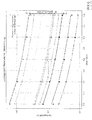
- Fig. 5 shows how the leakage time for the double stroke is divided between the time for the upward stroke and the time for the downward stroke in the piston pump used.
- the times for the two lifting movements are different. With these two times, the effectively conveyed volumes for each stroke direction can easily be calculated using linear relationships.
- Fig. 5 shows in the steeper graph on the left the measuring points during the upward movement of the piston.
- the piston needs approximately 5 seconds to move from bottom dead center to top dead center with a leakage volume of just over forty units. A much longer time is required for the movement from top dead center to bottom dead center, namely almost 30 seconds, as is illustrated by the measuring points running along the less steeply inclined line.
- Fig. 6 shows different curves for measurements using adhesives of different viscosity, each curve standing for a viscosity.
- the bottom curve illustrates the relationships at the lowest viscosity, the curves above it for adhesives of higher viscosity.
- the leakage time in seconds as a function of the pressure P acting on the piston 10 of the drive is illustrated for each curve.
- the points shown are measured and the curves calculated.
- a calculation model can be used if the pressure P, which acts on the drive of the piston pump, is changed.
- the calculation process compensates for the influence of pressure P on the amount of adhesive conveyed.
- the measured leakage times t Lauf and t Lab are corrected.
- the new corrected leakage times are in turn used as input values for the above calculation method.
- the calculation model can be developed on the basis of many experiments and is tailored to a specific piston pump. Other specific values apply to other pumps.
- the mass of adhesive is thus determined in two steps. First, with the help of the calculated leakage, the volume of adhesive delivered per unit of time and the number of products processed are determined. In a second step, the mass is determined from the adhesive with a previously determined density. Information on leakage and density must therefore be determined before the conveyed mass can be calculated. Based on this procedure, it is possible for the user to know the applied adhesive mass per product.
Claims (10)
- Procédé permettant de déterminer un volume effectivement refoulé Veff d'une pompe à piston (3) à double effet et à entraînement pneumatique à un consommateur pour un milieu liquide, en particulier un adhésif chauffé, la pompe à piston (3) étant affectée par des fuites, avec les particularités suivantes, sous l'effet d'une pression constante sur un entraînement de la pompe à piston (3) et à l'exécution d'au moins une course double de la pompe à piston (3) d'un point mort de celle-ci à l'autre point mort de celle-ci et en revenant audit un point mort :a. une durée de fuite tL auf pour une course de la pompe à piston (3) de son point mort bas à son point mort haut est mesurée sans que la pompe à piston (3) puisse refouler le milieu vers le consommateur,b. une durée de fuite tL ab pour une course de la pompe à piston (3) de son point mort haut à son point mort bas est mesurée sans que la pompe à piston (3) puisse refouler le milieu vers le consommateur,c. pour la course de la pompe à piston (3) du point mort bas au point mort haut, un quotient entre un volume théoriquement refoulé sans fuite du milieu Vauf de la pompe à piston (3) et la durée de fuite tL auf est déterminé,d. pour la course de la pompe à piston (3) du point mort haut au point mort bas, un quotient entre un volume théoriquement refoulé sans fuite Vab de la pompe à piston (3) et la durée de fuite tL ab est déterminé,e. lorsque le milieu est refoulé vers le consommateur, la durée tauf est mesurée pour la course de la pompe à piston (3) du point mort bas au point mort haut, et la durée tab est mesurée pour la course de la pompe à piston (3) du point mort haut au point mort bas,f. le volume effectivement refoulé Veff est multiplié par le nombre des courses doubles selon

- Procédé selon la revendication 1, dans lequel le volume effectivement refoulé Veff du milieu refoulé par rapport à sa masse m est déterminé, et la densité D du milieu est calculée selon

- Procédé selon la revendication 2, dans lequel, lorsque le milieu est refoulé vers le consommateur, la masse refoulée du milieu est calculée en continu en ce que le volume effectivement refoulé Veff calculé est multiplié par la densité D.
- Procédé selon l'une quelconque des revendications 1 à 3, dans lequel les étapes de procédé sont répétées après chaque variation des réglages de température du milieu à refouler vers le consommateur et/ou après chaque variation du milieu liquide, en particulier de l'adhésif chauffé, et/ou après chaque variation de la pression agissant sur l'entraînement de la pompe à piston (3).
- Procédé selon l'une quelconque des revendications 1 à 4, dans lequel les durées de fuite tL auf et tL ab et/ou une durée de fuite totale tLeck sont mesurées avant le début d'une production, en particulier automatiquement, avant le début de la production.
- Procédé selon l'une quelconque des revendications 1 à 5, dans lequel les durées de fuite et/ou les densités par type de milieu, en particulier par type d'adhésif, et la température sont mémorisées en vue d'une utilisation dans des productions ultérieures sous des conditions comparables sans nécessiter une nouvelle détermination.
- Procédé selon l'une quelconque des revendications 1 à 6, dans lequel, dans le cas d'une variation de la pression sur l'entraînement de la pompe à piston (3), les durées de fuites tL auf et tL ab mesurées à la pression de sortie ou la durée de fuite totale tLeck de celle-ci sont corrigées à l'aide d'un modèle de calcul basé sur l'expérimentation.
- Procédé selon l'une quelconque des revendications 1 à 7, dans lequel un message, en particulier concernant l'usure de la pompe à piston (3), est délivré lorsque d'importants écarts des durées de fuite actuellement mesurées par rapport aux valeurs mémorisées des durées de fuite sont déterminés.
- Procédé selon l'une quelconque des revendications 1 à 8, dans lequel des positions d'inversion d'un piston (10) de la pompe à piston (3) et/ou des positions intermédiaires du piston (10) entre les points d'inversion de celui-ci sont déterminées au moyen de capteurs à effet Hall (16, 17).
- Procédé selon la revendication 9, dans lequel le volume effectivement refoulé et/ou la masse refoulée est calculé(e)/sont calculés sur la base de la connaissance de la position du piston (10).
Priority Applications (3)
| Application Number | Priority Date | Filing Date | Title |
|---|---|---|---|
| EP18185230.2A EP3599377B1 (fr) | 2018-07-24 | 2018-07-24 | Procédé de détermination d'un volume transporté au moyen d'une pompe à piston ainsi que pompe à piston à double effet et pneumatique, destinée à la mise en uvre dudit procédé |
| US16/517,567 US20200032788A1 (en) | 2018-07-24 | 2019-07-20 | Piston Pump And Method For Determining Volume Delivered By Piston Pump |
| CN201910672005.1A CN110778487B (zh) | 2018-07-24 | 2019-07-24 | 用于确定借助活塞泵输送的体积的方法和起双重作用的能气动驱动的用于实施方法的活塞泵 |
Applications Claiming Priority (1)
| Application Number | Priority Date | Filing Date | Title |
|---|---|---|---|
| EP18185230.2A EP3599377B1 (fr) | 2018-07-24 | 2018-07-24 | Procédé de détermination d'un volume transporté au moyen d'une pompe à piston ainsi que pompe à piston à double effet et pneumatique, destinée à la mise en uvre dudit procédé |
Publications (2)
| Publication Number | Publication Date |
|---|---|
| EP3599377A1 EP3599377A1 (fr) | 2020-01-29 |
| EP3599377B1 true EP3599377B1 (fr) | 2020-11-04 |
Family
ID=63041898
Family Applications (1)
| Application Number | Title | Priority Date | Filing Date |
|---|---|---|---|
| EP18185230.2A Active EP3599377B1 (fr) | 2018-07-24 | 2018-07-24 | Procédé de détermination d'un volume transporté au moyen d'une pompe à piston ainsi que pompe à piston à double effet et pneumatique, destinée à la mise en uvre dudit procédé |
Country Status (3)
| Country | Link |
|---|---|
| US (1) | US20200032788A1 (fr) |
| EP (1) | EP3599377B1 (fr) |
| CN (1) | CN110778487B (fr) |
Families Citing this family (1)
| Publication number | Priority date | Publication date | Assignee | Title |
|---|---|---|---|---|
| DE102019112792A1 (de) * | 2019-05-15 | 2020-11-19 | Leistritz Pumpen Gmbh | Verfahren zur Ermittlung eines Durchflussvolumens eines durch eine Pumpe geförderten Fluids |
Family Cites Families (5)
| Publication number | Priority date | Publication date | Assignee | Title |
|---|---|---|---|---|
| DE3524241A1 (de) * | 1985-07-06 | 1987-01-08 | Bosch Gmbh Robert | Kraftstoffeinspritzpumpe fuer brennkraftmaschinen |
| DE10322221B3 (de) * | 2003-05-16 | 2005-01-27 | Lewa Herbert Ott Gmbh + Co | Leckageüberwachung im Hydraulikdruckraum einer Membranpumpe |
| KR101197406B1 (ko) | 2005-07-28 | 2012-11-05 | 그라코 미네소타 인크. | 전자식으로 모니터되는 에어 밸브 및 피스톤을 구비한 왕복펌프 |
| US9243626B2 (en) * | 2012-11-19 | 2016-01-26 | Nordson Corporation | Adhesive dispensing system and method including a pump with integrated diagnostics |
| US10046351B2 (en) * | 2014-07-14 | 2018-08-14 | Graco Minnesota Inc. | Material dispense tracking and control |
-
2018
- 2018-07-24 EP EP18185230.2A patent/EP3599377B1/fr active Active
-
2019
- 2019-07-20 US US16/517,567 patent/US20200032788A1/en not_active Abandoned
- 2019-07-24 CN CN201910672005.1A patent/CN110778487B/zh active Active
Non-Patent Citations (1)
| Title |
|---|
| None * |
Also Published As
| Publication number | Publication date |
|---|---|
| CN110778487B (zh) | 2023-05-23 |
| US20200032788A1 (en) | 2020-01-30 |
| CN110778487A (zh) | 2020-02-11 |
| EP3599377A1 (fr) | 2020-01-29 |
Similar Documents
| Publication | Publication Date | Title |
|---|---|---|
| DE102012105323B4 (de) | Steuervorrichtung zur Steuerung einer Kolbenpumpeneinheit für die Flüssigkeitschromatographie, insbesondere die Hochleistungsflüssigkeitschromatographie | |
| DE3239190C2 (fr) | ||
| DE2462651C3 (de) | Betonpumpe | |
| EP2212086B2 (fr) | Procédé et dispositif pour surveiller, documenter et/ou réguler une presse d'injection | |
| DE2911443C2 (de) | Druckmittelbetätigte Pumpe mit veränderbarem Fördervolumen | |
| EP2184492B1 (fr) | Procédé destiné à la commande de pompe péristaltique | |
| EP3296075B1 (fr) | Dispositif de transport d'une matière visqueuse provenant d'un récipient et procédé de fonctionnement du dispositif de transport | |
| DE19711292C2 (de) | Flüssigkeitschromatograph | |
| DE2612609A1 (de) | Pumpensystem | |
| DE4218320A1 (de) | Verfahren und Einrichtung zur Prüfung einer durch ein Medium angetriebenen Armatur | |
| DE102011052848A1 (de) | Vorrichtung zur Steuerung einer Kolbenpumpeneinheit für die Flüssigkeitschromatographie | |
| WO2013091992A1 (fr) | Procédé de dosage d'un milieu fluide | |
| DE102005051293B4 (de) | Vorrichtung zum Messen einer Durchsatzrate und Verfahren dafür | |
| EP3599377B1 (fr) | Procédé de détermination d'un volume transporté au moyen d'une pompe à piston ainsi que pompe à piston à double effet et pneumatique, destinée à la mise en uvre dudit procédé | |
| DE2709377A1 (de) | Vorrichtung zum messen einer brennstoffmenge | |
| EP2881584B1 (fr) | Détection de pannes sans capteur pour des pompes de dosage dotées d'un moteur pas à pas | |
| DE102005026374B4 (de) | Verfahren zum Aufbringen von Streifen aus pastösem Material | |
| EP3246568A1 (fr) | Système de pompe | |
| EP2840294B1 (fr) | Système de distribution de lubrifiant central d'une machine de thermoformage | |
| DE102016101584A1 (de) | Saugbandeinheit mit Stelleinrichtung zum Verstellen des Abstandes zwischen einer Pressscheibe der Saugbandeinheit und einem Schaberelement sowie Verfahren hierzu | |
| EP3904679B1 (fr) | Procédé de fonctionnement d'une pompe à piston à double action, pompe à piston à double action ainsi que système d'application permettant d'appliquer un milieu fluide à un substrat | |
| DE102015120381A1 (de) | Automatische Förderdruckregelung | |
| DE3305643C2 (fr) | ||
| DE10135448A1 (de) | Vorrichtung zur Erfassung von Fluidverunreinigungen | |
| DE2347493C2 (de) | Dosiervorrichtung zur durchflußabhängigen Dosierung von Fluids |
Legal Events
| Date | Code | Title | Description |
|---|---|---|---|
| PUAI | Public reference made under article 153(3) epc to a published international application that has entered the european phase |
Free format text: ORIGINAL CODE: 0009012 |
|
| STAA | Information on the status of an ep patent application or granted ep patent |
Free format text: STATUS: REQUEST FOR EXAMINATION WAS MADE |
|
| 17P | Request for examination filed |
Effective date: 20181220 |
|
| AK | Designated contracting states |
Kind code of ref document: A1 Designated state(s): AL AT BE BG CH CY CZ DE DK EE ES FI FR GB GR HR HU IE IS IT LI LT LU LV MC MK MT NL NO PL PT RO RS SE SI SK SM TR |
|
| AX | Request for extension of the european patent |
Extension state: BA ME |
|
| GRAP | Despatch of communication of intention to grant a patent |
Free format text: ORIGINAL CODE: EPIDOSNIGR1 |
|
| STAA | Information on the status of an ep patent application or granted ep patent |
Free format text: STATUS: GRANT OF PATENT IS INTENDED |
|
| RIC1 | Information provided on ipc code assigned before grant |
Ipc: F04B 15/02 20060101ALI20200622BHEP Ipc: F04B 49/06 20060101ALI20200622BHEP Ipc: F04B 51/00 20060101ALI20200622BHEP Ipc: F04B 13/00 20060101AFI20200622BHEP |
|
| INTG | Intention to grant announced |
Effective date: 20200720 |
|
| RIN1 | Information on inventor provided before grant (corrected) |
Inventor name: MOESLI, URS Inventor name: HOFER, ANDREAS Inventor name: FELIX, HANSPETER |
|
| GRAS | Grant fee paid |
Free format text: ORIGINAL CODE: EPIDOSNIGR3 |
|
| GRAA | (expected) grant |
Free format text: ORIGINAL CODE: 0009210 |
|
| STAA | Information on the status of an ep patent application or granted ep patent |
Free format text: STATUS: THE PATENT HAS BEEN GRANTED |
|
| AK | Designated contracting states |
Kind code of ref document: B1 Designated state(s): AL AT BE BG CH CY CZ DE DK EE ES FI FR GB GR HR HU IE IS IT LI LT LU LV MC MK MT NL NO PL PT RO RS SE SI SK SM TR |
|
| REG | Reference to a national code |
Ref country code: GB Ref legal event code: FG4D Free format text: NOT ENGLISH |
|
| RIN1 | Information on inventor provided before grant (corrected) |
Inventor name: HOFER, ANDREAS Inventor name: FELIX, HANSPETER Inventor name: MOESLI, URS |
|
| REG | Reference to a national code |
Ref country code: CH Ref legal event code: EP |
|
| REG | Reference to a national code |
Ref country code: AT Ref legal event code: REF Ref document number: 1331156 Country of ref document: AT Kind code of ref document: T Effective date: 20201115 |
|
| REG | Reference to a national code |
Ref country code: IE Ref legal event code: FG4D Free format text: LANGUAGE OF EP DOCUMENT: GERMAN |
|
| REG | Reference to a national code |
Ref country code: DE Ref legal event code: R096 Ref document number: 502018002891 Country of ref document: DE |
|
| REG | Reference to a national code |
Ref country code: NL Ref legal event code: MP Effective date: 20201104 |
|
| PG25 | Lapsed in a contracting state [announced via postgrant information from national office to epo] |
Ref country code: GR Free format text: LAPSE BECAUSE OF FAILURE TO SUBMIT A TRANSLATION OF THE DESCRIPTION OR TO PAY THE FEE WITHIN THE PRESCRIBED TIME-LIMIT Effective date: 20210205 Ref country code: NO Free format text: LAPSE BECAUSE OF FAILURE TO SUBMIT A TRANSLATION OF THE DESCRIPTION OR TO PAY THE FEE WITHIN THE PRESCRIBED TIME-LIMIT Effective date: 20210204 Ref country code: PT Free format text: LAPSE BECAUSE OF FAILURE TO SUBMIT A TRANSLATION OF THE DESCRIPTION OR TO PAY THE FEE WITHIN THE PRESCRIBED TIME-LIMIT Effective date: 20210304 Ref country code: RS Free format text: LAPSE BECAUSE OF FAILURE TO SUBMIT A TRANSLATION OF THE DESCRIPTION OR TO PAY THE FEE WITHIN THE PRESCRIBED TIME-LIMIT Effective date: 20201104 Ref country code: FI Free format text: LAPSE BECAUSE OF FAILURE TO SUBMIT A TRANSLATION OF THE DESCRIPTION OR TO PAY THE FEE WITHIN THE PRESCRIBED TIME-LIMIT Effective date: 20201104 |
|
| PG25 | Lapsed in a contracting state [announced via postgrant information from national office to epo] |
Ref country code: BG Free format text: LAPSE BECAUSE OF FAILURE TO SUBMIT A TRANSLATION OF THE DESCRIPTION OR TO PAY THE FEE WITHIN THE PRESCRIBED TIME-LIMIT Effective date: 20210204 Ref country code: SE Free format text: LAPSE BECAUSE OF FAILURE TO SUBMIT A TRANSLATION OF THE DESCRIPTION OR TO PAY THE FEE WITHIN THE PRESCRIBED TIME-LIMIT Effective date: 20201104 Ref country code: PL Free format text: LAPSE BECAUSE OF FAILURE TO SUBMIT A TRANSLATION OF THE DESCRIPTION OR TO PAY THE FEE WITHIN THE PRESCRIBED TIME-LIMIT Effective date: 20201104 Ref country code: IS Free format text: LAPSE BECAUSE OF FAILURE TO SUBMIT A TRANSLATION OF THE DESCRIPTION OR TO PAY THE FEE WITHIN THE PRESCRIBED TIME-LIMIT Effective date: 20210304 Ref country code: LV Free format text: LAPSE BECAUSE OF FAILURE TO SUBMIT A TRANSLATION OF THE DESCRIPTION OR TO PAY THE FEE WITHIN THE PRESCRIBED TIME-LIMIT Effective date: 20201104 Ref country code: ES Free format text: LAPSE BECAUSE OF FAILURE TO SUBMIT A TRANSLATION OF THE DESCRIPTION OR TO PAY THE FEE WITHIN THE PRESCRIBED TIME-LIMIT Effective date: 20201104 |
|
| REG | Reference to a national code |
Ref country code: LT Ref legal event code: MG9D |
|
| PG25 | Lapsed in a contracting state [announced via postgrant information from national office to epo] |
Ref country code: HR Free format text: LAPSE BECAUSE OF FAILURE TO SUBMIT A TRANSLATION OF THE DESCRIPTION OR TO PAY THE FEE WITHIN THE PRESCRIBED TIME-LIMIT Effective date: 20201104 |
|
| PG25 | Lapsed in a contracting state [announced via postgrant information from national office to epo] |
Ref country code: LT Free format text: LAPSE BECAUSE OF FAILURE TO SUBMIT A TRANSLATION OF THE DESCRIPTION OR TO PAY THE FEE WITHIN THE PRESCRIBED TIME-LIMIT Effective date: 20201104 Ref country code: RO Free format text: LAPSE BECAUSE OF FAILURE TO SUBMIT A TRANSLATION OF THE DESCRIPTION OR TO PAY THE FEE WITHIN THE PRESCRIBED TIME-LIMIT Effective date: 20201104 Ref country code: SK Free format text: LAPSE BECAUSE OF FAILURE TO SUBMIT A TRANSLATION OF THE DESCRIPTION OR TO PAY THE FEE WITHIN THE PRESCRIBED TIME-LIMIT Effective date: 20201104 Ref country code: EE Free format text: LAPSE BECAUSE OF FAILURE TO SUBMIT A TRANSLATION OF THE DESCRIPTION OR TO PAY THE FEE WITHIN THE PRESCRIBED TIME-LIMIT Effective date: 20201104 Ref country code: CZ Free format text: LAPSE BECAUSE OF FAILURE TO SUBMIT A TRANSLATION OF THE DESCRIPTION OR TO PAY THE FEE WITHIN THE PRESCRIBED TIME-LIMIT Effective date: 20201104 Ref country code: SM Free format text: LAPSE BECAUSE OF FAILURE TO SUBMIT A TRANSLATION OF THE DESCRIPTION OR TO PAY THE FEE WITHIN THE PRESCRIBED TIME-LIMIT Effective date: 20201104 |
|
| REG | Reference to a national code |
Ref country code: DE Ref legal event code: R097 Ref document number: 502018002891 Country of ref document: DE |
|
| PG25 | Lapsed in a contracting state [announced via postgrant information from national office to epo] |
Ref country code: DK Free format text: LAPSE BECAUSE OF FAILURE TO SUBMIT A TRANSLATION OF THE DESCRIPTION OR TO PAY THE FEE WITHIN THE PRESCRIBED TIME-LIMIT Effective date: 20201104 |
|
| PLBE | No opposition filed within time limit |
Free format text: ORIGINAL CODE: 0009261 |
|
| STAA | Information on the status of an ep patent application or granted ep patent |
Free format text: STATUS: NO OPPOSITION FILED WITHIN TIME LIMIT |
|
| 26N | No opposition filed |
Effective date: 20210805 |
|
| PG25 | Lapsed in a contracting state [announced via postgrant information from national office to epo] |
Ref country code: AL Free format text: LAPSE BECAUSE OF FAILURE TO SUBMIT A TRANSLATION OF THE DESCRIPTION OR TO PAY THE FEE WITHIN THE PRESCRIBED TIME-LIMIT Effective date: 20201104 Ref country code: NL Free format text: LAPSE BECAUSE OF FAILURE TO SUBMIT A TRANSLATION OF THE DESCRIPTION OR TO PAY THE FEE WITHIN THE PRESCRIBED TIME-LIMIT Effective date: 20201104 |
|
| PG25 | Lapsed in a contracting state [announced via postgrant information from national office to epo] |
Ref country code: SI Free format text: LAPSE BECAUSE OF FAILURE TO SUBMIT A TRANSLATION OF THE DESCRIPTION OR TO PAY THE FEE WITHIN THE PRESCRIBED TIME-LIMIT Effective date: 20201104 |
|
| PG25 | Lapsed in a contracting state [announced via postgrant information from national office to epo] |
Ref country code: MC Free format text: LAPSE BECAUSE OF FAILURE TO SUBMIT A TRANSLATION OF THE DESCRIPTION OR TO PAY THE FEE WITHIN THE PRESCRIBED TIME-LIMIT Effective date: 20201104 |
|
| REG | Reference to a national code |
Ref country code: BE Ref legal event code: MM Effective date: 20210731 |
|
| PG25 | Lapsed in a contracting state [announced via postgrant information from national office to epo] |
Ref country code: IS Free format text: LAPSE BECAUSE OF FAILURE TO SUBMIT A TRANSLATION OF THE DESCRIPTION OR TO PAY THE FEE WITHIN THE PRESCRIBED TIME-LIMIT Effective date: 20210304 Ref country code: LU Free format text: LAPSE BECAUSE OF NON-PAYMENT OF DUE FEES Effective date: 20210724 |
|
| PG25 | Lapsed in a contracting state [announced via postgrant information from national office to epo] |
Ref country code: IE Free format text: LAPSE BECAUSE OF NON-PAYMENT OF DUE FEES Effective date: 20210724 Ref country code: BE Free format text: LAPSE BECAUSE OF NON-PAYMENT OF DUE FEES Effective date: 20210731 |
|
| GBPC | Gb: european patent ceased through non-payment of renewal fee |
Effective date: 20220724 |
|
| PG25 | Lapsed in a contracting state [announced via postgrant information from national office to epo] |
Ref country code: GB Free format text: LAPSE BECAUSE OF NON-PAYMENT OF DUE FEES Effective date: 20220724 |
|
| P01 | Opt-out of the competence of the unified patent court (upc) registered |
Effective date: 20230517 |
|
| PG25 | Lapsed in a contracting state [announced via postgrant information from national office to epo] |
Ref country code: CY Free format text: LAPSE BECAUSE OF FAILURE TO SUBMIT A TRANSLATION OF THE DESCRIPTION OR TO PAY THE FEE WITHIN THE PRESCRIBED TIME-LIMIT Effective date: 20201104 |
|
| PG25 | Lapsed in a contracting state [announced via postgrant information from national office to epo] |
Ref country code: HU Free format text: LAPSE BECAUSE OF FAILURE TO SUBMIT A TRANSLATION OF THE DESCRIPTION OR TO PAY THE FEE WITHIN THE PRESCRIBED TIME-LIMIT; INVALID AB INITIO Effective date: 20180724 |
|
| PGFP | Annual fee paid to national office [announced via postgrant information from national office to epo] |
Ref country code: IT Payment date: 20230724 Year of fee payment: 6 Ref country code: CH Payment date: 20230801 Year of fee payment: 6 |
|
| PGFP | Annual fee paid to national office [announced via postgrant information from national office to epo] |
Ref country code: FR Payment date: 20230726 Year of fee payment: 6 Ref country code: DE Payment date: 20230823 Year of fee payment: 6 |