EP3246568A1 - Système de pompe - Google Patents
Système de pompe Download PDFInfo
- Publication number
- EP3246568A1 EP3246568A1 EP17156863.7A EP17156863A EP3246568A1 EP 3246568 A1 EP3246568 A1 EP 3246568A1 EP 17156863 A EP17156863 A EP 17156863A EP 3246568 A1 EP3246568 A1 EP 3246568A1
- Authority
- EP
- European Patent Office
- Prior art keywords
- pressure
- drive
- pump arrangement
- piston
- drive fluid
- Prior art date
- Legal status (The legal status is an assumption and is not a legal conclusion. Google has not performed a legal analysis and makes no representation as to the accuracy of the status listed.)
- Granted
Links
- 239000012530 fluid Substances 0.000 claims abstract description 71
- 239000007788 liquid Substances 0.000 claims abstract description 29
- 238000011156 evaluation Methods 0.000 claims abstract description 25
- 239000002245 particle Substances 0.000 claims abstract description 16
- 238000012806 monitoring device Methods 0.000 claims abstract description 14
- 238000005086 pumping Methods 0.000 claims abstract description 14
- 238000012544 monitoring process Methods 0.000 claims abstract description 13
- 238000012545 processing Methods 0.000 claims abstract description 7
- 238000007599 discharging Methods 0.000 claims abstract description 4
- 238000000034 method Methods 0.000 claims description 8
- XLYOFNOQVPJJNP-UHFFFAOYSA-N water Substances O XLYOFNOQVPJJNP-UHFFFAOYSA-N 0.000 description 12
- 238000009530 blood pressure measurement Methods 0.000 description 6
- 230000001133 acceleration Effects 0.000 description 3
- 239000012080 ambient air Substances 0.000 description 3
- 239000003921 oil Substances 0.000 description 3
- 230000000007 visual effect Effects 0.000 description 3
- 230000000712 assembly Effects 0.000 description 2
- 238000000429 assembly Methods 0.000 description 2
- 238000004140 cleaning Methods 0.000 description 2
- 238000010276 construction Methods 0.000 description 2
- 230000000694 effects Effects 0.000 description 2
- 238000011010 flushing procedure Methods 0.000 description 2
- 239000010720 hydraulic oil Substances 0.000 description 2
- 230000002093 peripheral effect Effects 0.000 description 2
- 238000007789 sealing Methods 0.000 description 2
- 239000007787 solid Substances 0.000 description 2
- 230000001360 synchronised effect Effects 0.000 description 2
- 239000002351 wastewater Substances 0.000 description 2
- 208000010201 Exanthema Diseases 0.000 description 1
- 230000009286 beneficial effect Effects 0.000 description 1
- 238000002485 combustion reaction Methods 0.000 description 1
- 238000012937 correction Methods 0.000 description 1
- 230000008878 coupling Effects 0.000 description 1
- 238000010168 coupling process Methods 0.000 description 1
- 238000005859 coupling reaction Methods 0.000 description 1
- 230000002950 deficient Effects 0.000 description 1
- 238000013461 design Methods 0.000 description 1
- 230000006866 deterioration Effects 0.000 description 1
- 238000010586 diagram Methods 0.000 description 1
- 238000006073 displacement reaction Methods 0.000 description 1
- 201000005884 exanthem Diseases 0.000 description 1
- 239000000835 fiber Substances 0.000 description 1
- -1 for example Substances 0.000 description 1
- 239000011344 liquid material Substances 0.000 description 1
- 239000000203 mixture Substances 0.000 description 1
- 239000003380 propellant Substances 0.000 description 1
- 206010037844 rash Diseases 0.000 description 1
- 239000004576 sand Substances 0.000 description 1
- 239000011343 solid material Substances 0.000 description 1
- 239000000126 substance Substances 0.000 description 1
Images

Classifications
-
- F—MECHANICAL ENGINEERING; LIGHTING; HEATING; WEAPONS; BLASTING
- F04—POSITIVE - DISPLACEMENT MACHINES FOR LIQUIDS; PUMPS FOR LIQUIDS OR ELASTIC FLUIDS
- F04B—POSITIVE-DISPLACEMENT MACHINES FOR LIQUIDS; PUMPS
- F04B9/00—Piston machines or pumps characterised by the driving or driven means to or from their working members
- F04B9/08—Piston machines or pumps characterised by the driving or driven means to or from their working members the means being fluid
- F04B9/10—Piston machines or pumps characterised by the driving or driven means to or from their working members the means being fluid the fluid being liquid
-
- F—MECHANICAL ENGINEERING; LIGHTING; HEATING; WEAPONS; BLASTING
- F04—POSITIVE - DISPLACEMENT MACHINES FOR LIQUIDS; PUMPS FOR LIQUIDS OR ELASTIC FLUIDS
- F04B—POSITIVE-DISPLACEMENT MACHINES FOR LIQUIDS; PUMPS
- F04B51/00—Testing machines, pumps, or pumping installations
-
- F—MECHANICAL ENGINEERING; LIGHTING; HEATING; WEAPONS; BLASTING
- F04—POSITIVE - DISPLACEMENT MACHINES FOR LIQUIDS; PUMPS FOR LIQUIDS OR ELASTIC FLUIDS
- F04B—POSITIVE-DISPLACEMENT MACHINES FOR LIQUIDS; PUMPS
- F04B49/00—Control, e.g. of pump delivery, or pump pressure of, or safety measures for, machines, pumps, or pumping installations, not otherwise provided for, or of interest apart from, groups F04B1/00 - F04B47/00
- F04B49/10—Other safety measures
-
- F—MECHANICAL ENGINEERING; LIGHTING; HEATING; WEAPONS; BLASTING
- F04—POSITIVE - DISPLACEMENT MACHINES FOR LIQUIDS; PUMPS FOR LIQUIDS OR ELASTIC FLUIDS
- F04B—POSITIVE-DISPLACEMENT MACHINES FOR LIQUIDS; PUMPS
- F04B15/00—Pumps adapted to handle specific fluids, e.g. by selection of specific materials for pumps or pump parts
- F04B15/02—Pumps adapted to handle specific fluids, e.g. by selection of specific materials for pumps or pump parts the fluids being viscous or non-homogeneous
-
- F—MECHANICAL ENGINEERING; LIGHTING; HEATING; WEAPONS; BLASTING
- F04—POSITIVE - DISPLACEMENT MACHINES FOR LIQUIDS; PUMPS FOR LIQUIDS OR ELASTIC FLUIDS
- F04B—POSITIVE-DISPLACEMENT MACHINES FOR LIQUIDS; PUMPS
- F04B53/00—Component parts, details or accessories not provided for in, or of interest apart from, groups F04B1/00 - F04B23/00 or F04B39/00 - F04B47/00
- F04B53/10—Valves; Arrangement of valves
- F04B53/12—Valves; Arrangement of valves arranged in or on pistons
- F04B53/121—Valves; Arrangement of valves arranged in or on pistons the valve being an annular ring surrounding the piston, e.g. an O-ring
-
- F—MECHANICAL ENGINEERING; LIGHTING; HEATING; WEAPONS; BLASTING
- F04—POSITIVE - DISPLACEMENT MACHINES FOR LIQUIDS; PUMPS FOR LIQUIDS OR ELASTIC FLUIDS
- F04B—POSITIVE-DISPLACEMENT MACHINES FOR LIQUIDS; PUMPS
- F04B53/00—Component parts, details or accessories not provided for in, or of interest apart from, groups F04B1/00 - F04B23/00 or F04B39/00 - F04B47/00
- F04B53/14—Pistons, piston-rods or piston-rod connections
-
- F—MECHANICAL ENGINEERING; LIGHTING; HEATING; WEAPONS; BLASTING
- F04—POSITIVE - DISPLACEMENT MACHINES FOR LIQUIDS; PUMPS FOR LIQUIDS OR ELASTIC FLUIDS
- F04B—POSITIVE-DISPLACEMENT MACHINES FOR LIQUIDS; PUMPS
- F04B53/00—Component parts, details or accessories not provided for in, or of interest apart from, groups F04B1/00 - F04B23/00 or F04B39/00 - F04B47/00
- F04B53/16—Casings; Cylinders; Cylinder liners or heads; Fluid connections
-
- F—MECHANICAL ENGINEERING; LIGHTING; HEATING; WEAPONS; BLASTING
- F04—POSITIVE - DISPLACEMENT MACHINES FOR LIQUIDS; PUMPS FOR LIQUIDS OR ELASTIC FLUIDS
- F04B—POSITIVE-DISPLACEMENT MACHINES FOR LIQUIDS; PUMPS
- F04B9/00—Piston machines or pumps characterised by the driving or driven means to or from their working members
- F04B9/08—Piston machines or pumps characterised by the driving or driven means to or from their working members the means being fluid
- F04B9/10—Piston machines or pumps characterised by the driving or driven means to or from their working members the means being fluid the fluid being liquid
- F04B9/109—Piston machines or pumps characterised by the driving or driven means to or from their working members the means being fluid the fluid being liquid having plural pumping chambers
- F04B9/111—Piston machines or pumps characterised by the driving or driven means to or from their working members the means being fluid the fluid being liquid having plural pumping chambers with two mechanically connected pumping members
- F04B9/113—Piston machines or pumps characterised by the driving or driven means to or from their working members the means being fluid the fluid being liquid having plural pumping chambers with two mechanically connected pumping members reciprocating movement of the pumping members being obtained by a double-acting liquid motor
Definitions
- the present invention relates to a pump arrangement for pumping a, in particular contaminated with dirt particles, liquid, the pump assembly having at least one working space and at least one delivery piston, and at least one inlet valve and at least one outlet valve, and the delivery piston, for sucking liquid through the inlet valve in the working space and for discharging liquid through the outlet valve from the working space, movable, and the pump assembly comprises a wear monitoring device for monitoring the wear of the inlet valve and / or outlet valve with at least one pressure transducer and a pressure evaluation unit for processing issued by the pressure transducer pressure readings. Furthermore, the invention also relates to a method for monitoring the wear of at least one inlet valve and / or at least one outlet valve of a pump arrangement.
- Pump arrangements for pumping, in particular contaminated with dirt particles, liquids are, for example, for pumping waste water from channels, storage tanks, etc. or for flushing sewers, boreholes, etc. used.
- dirt particles in the form of solid particles (eg sand or stones) or in the form of fibers are present.
- dirt particles from solids can have an abrasive effect and lead to wear of the components of the pump arrangement, for example the inlet valves and / or outlet valves. If dirt particles are trapped in the inlet and / or outlet valve when closing the inlet and / or outlet valve, locally high flow velocities can occur.
- WO 2007/072385 A2 is a pump assembly of the type mentioned for flushing boreholes with a driven by a rotating crankshaft delivery piston shown.
- the proposed according to this document wear monitoring device allows monitoring of the wear of the intake and / or the exhaust valve by means disposed in the working space pressure and acceleration sensors. In a downstream of the working space high pressure section another pressure transducer is arranged. The pressure and acceleration sensors are in direct contact with the fluid to be delivered. When pumping, in particular contaminated with dirt particles, liquid pressure and acceleration sensors are thus exposed directly to the abrasive effect of the medium.
- the object of the invention is to provide an advantageous pump arrangement of the type mentioned, which is also suitable for pumping heavily contaminated with dirt particles liquids.
- the pumping arrangement for moving the delivery piston comprises a drive fluid system operable with a drive fluid, and the pressure sensor of the wear monitoring device is arranged for detecting the pressure of the drive fluid in the drive fluid system.
- a wear of the at least one inlet valve and / or the at least one outlet valve can thus be detected without the pressure sensor being in direct contact with the liquid contaminated, in particular with dirt particles.
- the drive fluid is a liquid medium, in particular hydraulic oil.
- a gaseous propellant fluid e.g. Ambient air.
- the drive fluid system could be designed as an open drive fluid system.
- An open drive fluid system could be e.g. prove beneficial in the use of ambient air as the drive fluid, in which case preferably ambient air is removed from the atmosphere and compressed and in turn fed to the atmosphere after use in the drive fluid system.
- the drive fluid system is a closed drive fluid system wherein the drive fluid is conveyed in a closed loop. In such cases, one could also speak of a drive fluid circuit.
- a drive piston is movably mounted in a drive cylinder of the drive fluid system, which is mechanically coupled to the at least one delivery piston.
- the drive piston and the at least one delivery piston For example, could be mechanically coupled to each other by means of a common piston rod.
- An articulated mechanical coupling of the drive piston and the at least one delivery piston is conceivable and possible.
- a direct interconnection of drive and delivery pistons is possible.
- the delivery piston could generally also be referred to as a displacement body.
- the volume of the working space is increased by the movement of the delivery piston for sucking liquid into the working space and reduced to eject liquid from the working space.
- the delivery piston is mounted in a delivery cylinder, preferably linear, movable. The working space is then in the delivery cylinder.
- the pump arrangement comprises two delivery pistons, which are connected to the or a drive piston movably mounted in a drive cylinder of the drive fluid system, preferably rigidly.
- the drive piston is arranged between the two delivery pistons. A rigid connection of the drive piston with the two delivery pistons allows a synchronous lifting movement of the delivery piston and the drive piston.
- the delivery piston is designed as a plunger.
- Plungers also called plungers, are characterized by a simple construction. The plunger displaces by its volume while reducing the volume of the working space, the liquid to be conveyed from the delivery cylinder.
- a seal arranged stationarily on the delivery cylinder may be provided, wherein a relative movement of the delivery piston relative to the seal takes place during the pumping process.
- the delivery piston has at least one circumferential seal.
- the seal preferably stationary, arranged on the delivery piston, whereby a relative movement of the seal relative to the delivery cylinder takes place.
- the pump assembly has two working spaces, the delivery piston separating a first of the working spaces and a second of the working spaces, and each of the working spaces having at least one inlet valve and at least one outlet valve assigned.
- the delivery piston thus conveniently acts double-acting, i. that one of the two working spaces for the suction of liquid through the inlet valve is increased, while the second working space is reduced at the same time for discharging liquid through the outlet valve.
- the pressure evaluation unit of the wear monitoring device advantageously has a memory for storing pressure measurement values and a microprocessor for processing the pressure measurement values.
- the pressure evaluation unit could also be integrated in a control device of the pump arrangement.
- the wear monitoring device comprises a reporting unit for informing a user in the presence of a detected by the pressure evaluation unit wear of the at least one inlet valve and / or the at least one exhaust valve.
- the annunciator could output visual and / or audible information to the user.
- continuous, in particular visual, operating data about the state of the intake valve and / or exhaust valve are output to the user.
- the pump arrangement according to the invention comprises at least one proximity switch for detecting an end position, preferably the end positions, of the delivery piston and / or the or one in one Drive cylinder of the drive fluid system movably mounted drive piston on.
- a proximity switch By providing a proximity switch, the position of the delivery piston and / or the drive piston in the monitoring of the wear of the inlet valve and / or the exhaust valve of the pressure evaluation unit in the processing of pressure readings can be taken into account.
- the pump arrangement has exactly one pressure sensor for measuring the pressure of the drive fluid, wherein the pressure sensor is arranged between a, preferably volumengeregelten, drive fluid pump and a switching valve for controlling the direction of movement of the at least one delivery piston.
- the drive fluid pump and the changeover valve are preferably components of the drive fluid system.
- a pressure transducer for measuring the pressure of the drive fluid in a first and a second direction of movement of the drive piston and / or delivery piston can be used.
- the present invention also relates to a method for monitoring the wear of at least one inlet valve and / or at least one outlet valve of a pump arrangement according to the invention.
- the pressure evaluation unit forms at least one characteristic value from pressure measurements processed during a lifting operation of the delivery piston, and the characteristic values of a sequence of lifting operations are evaluated.
- the pressure evaluation unit from processed pressure measured values during a stroke of the drive piston in a first direction of movement a first characteristic and from processed pressure readings of a subsequent stroke of the drive piston in a second direction of movement, which is opposite to the first direction of movement, a second characteristic value, wherein the difference Characteristic values with one in advance defined threshold value are compared.
- the first characteristic value is an increase value of the pressure rise during the stroke of the drive piston in the first direction of movement and the second characteristic value is an increase value of the pressure increase during the stroke of the drive piston in the second direction of movement.
- the pressure evaluation unit from processed pressure measurement values during a stroke of the drive piston forms a characteristic value which is compared with a reference value.
- the reference value is determined for intact intake valves and / or exhaust valves.
- the reference value could be determined, for example, during the first startup of the pump arrangement and stored in the pressure evaluation unit.
- the reference value could also be assigned a tolerance range. Then it could be provided that it is only then recognized that wear is present if the determined characteristic value lies outside the tolerance range surrounding the reference value.
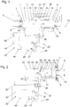
- Fig. 1 and 2 are two embodiments of pump assemblies for pumping, in particular contaminated with dirt particles, liquid shown.
- a pump arrangement could, for. B. at one Canal cleaning vehicle be arranged.
- the contaminated especially with dirt particles, liquid referred to as dirty water
- the pump assemblies according to the invention can be used for other liquids.
- Dirty water often has abrasive dirt particles in the form of granular and / or fibrous substances.
- the pump assembly according to the invention could also be used for pumping other mixtures of liquid and solid materials, eg liquid concrete.
- the pump arrangement for pumping dirty water has two delivery cylinders 5, 6, each with a working space 1, 2.
- a delivery piston 3 and in the delivery cylinder 6, a delivery piston 4 is arranged to be linearly movable.
- the delivery piston 3, 4 are formed in this embodiment as a plunger.
- the sealing of the working space 1, 2 with respect to the conveyor cylinder 5, 6 and the respective delivery piston 3, 4 is effected by the respective delivery cylinder 5, 6 fixedly arranged seals 16.
- the sixth is the volume of the workrooms 1, 2 changeable.
- Each working chamber 1, 2 is associated with an inlet valve 7 and an outlet valve 8, respectively.
- the intake valves 7 and exhaust valves 8 are designed as spring-biased check valves and known per se. If the at least one inlet valve 7 and / or the at least one outlet valve 8 are intact, one of the passage directions for liquid is blocked in a closed position. In the opposite passage direction, liquid can flow through the opened inlet valve 7 and / or outlet valve 8.
- the valve disks of the intake valves 7 and exhaust valves 8, which are shown schematically, are thus spring-biased in the closed position against a corresponding valve seat, cf. Fig. 1 ,
- the intake valves 7 are connected to a suction port 9 of the pump arrangement fluidly connected.
- a suction line not shown, for receiving dirty water or in general of, in particular contaminated with dirt particles, liquid can be connected.
- the exhaust valves 8 are fluidly connected to an outlet port 10 of the pump assembly. From the outlet port 10 away, a line also not shown in a, for example, arranged on a sewer cleaning vehicle, storage tank for wastewater could lead.
- the pump assembly includes a drive fluid system 20 operable with a drive fluid.
- drive fluid for example, hydraulic oil can be used.
- the drive fluid system 20 is in the embodiments shown herein as a closed system, i. the drive fluid is conveyed in a circuit in the drive fluid system 22.
- the drive fluid system 20 has a volume-controlled drive fluid pump 27 which can be driven, for example, by means of an electric motor 28. Instead of an electric motor, e.g. Also, an internal combustion engine, a hydraulic motor or the like can be used.
- the volume-controlled drive fluid pump 27 shown here in the exemplary embodiment shown provides a constant volume flow for moving a drive piston 21, for example, preselected by the user by means of a control device 30 of the pump arrangement.
- the drive piston 21 is mounted linearly movable in a drive cylinder 22 of the drive fluid system 20.
- the drive piston 21 having a circumferential seal separates a first drive space 23 and a second drive space 24 from each other.
- a switching valve 26 alternately supplies the pressurized drive fluid to the first drive space 23 or the second drive space 24, while drive fluid is discharged from the other of the two drive spaces 23, 24 and collected in an oil pan 29 of the drive fluid system 20.
- the drive fluid collected in the oil sump 29 can subsequently be sucked in again by the drive fluid pump 27, thus closing the circuit of the drive fluid system 20 is.
- the switching valve 26 of the drive fluid system 20 can be controlled by means of the control device 30 of the pump arrangement.
- the pump assembly according to Fig. 1 further comprises two proximity switches 43 for detecting the end positions of the drive piston 21.
- the signal of the proximity switch 43 is evaluated by the control unit 30, wherein the switching valve 26 is switched on reaching an end position to reverse the direction of movement of the drive piston 21.
- the proximity switches 43 are arranged on the delivery cylinders 5, 6. The end positions of the drive piston 21 are thus indirectly output to the control device 30 via a signal of the corresponding proximity switch 43 caused by the presence of one of the delivery pistons 3, 4 at the respective end position.
- the delivery pistons 3, 4 are rigidly connected to the drive piston 21.
- the drive piston 21 is arranged in this embodiment between the delivery piston 3, 4. With this arrangement, it is possible to allow continuous discharge of dirty water from the side of the suction port 9 to the side of the outlet port 10.
- dirty water is sucked into the working space 1 via the suction connection 9 through the inlet valve 7 assigned to the working space 1 ,
- the valve plate of the inlet valve 7 is lifted by the negative pressure arising in the working space 1 from the valve seat, wherein liquid flows from the suction port 9 into the working space 1.
- the outlet valve 8 associated with the first working space 1 is in the closed position when the delivery piston 3 moves in the first direction of movement 31 and, with an intact outlet valve 8, prevents backflow of dirty water via the outlet connection 10 into the working space 1.
- end position which is determined by the arranged on the delivery cylinder 6 proximity switch 43, the direction of movement of the drive piston 21 and the delivery piston 3, 4 reversed by switching the switching valve 26.
- a movement of the delivery pistons 3, 4 in the second movement direction 32 directed counter to the first movement direction 31 a collection of dirty water takes place through the suction connection 9 into the working space 2 and an expulsion of dirty water from the working space 1 toward the outlet connection 10.
- the first drive chamber 23 and the second drive chamber 24 are each sealed by means of a seal 16 against the, in normal operation filled with dirty water, working spaces 1, 2.
- the pump arrangement has a wear monitoring device 40 for monitoring the wear of the inlet valve 7 and / or the outlet valve 8.
- a pressure sensor 41 of the wear monitoring device 40 for detecting the pressure of the drive fluid in the drive fluid system 20 is arranged.
- the pressure readings issued by the pressure transducer 41 are processed by a pressure evaluation unit 42.
- the pressure transducer 41 is disposed between the drive fluid pump 27 and the switching valve 26. Thereby, a single pressure transducer 41 for detecting the pressure of the drive fluid during the movement of the drive piston 21 in the first direction of movement 31 and the Detecting the pressure of the drive fluid in the second direction of movement 32 done.
- the arrangement of the pressure transducer 41 between the drive fluid pump 27 and the switching valve 26 can be dispensed with an additional pressure transducer 41. It would also be conceivable and possible in other embodiments to measure the pressure at another location in the drive fluid system 20, for. B. at the respective connecting line between the first drive chamber 23 and the switching valve 26 and the second drive chamber 24 and the switching valve 26th
- the wear monitoring device 40 has a reporting unit 44 for audible and / or visual information of a user in the presence of a detected by the pressure evaluation unit 42 wear of the at least one inlet valve 7 and / or the at least one exhaust valve 8.
- the wear of the at least one inlet valve 7 and / or of the at least one outlet valve 8 occurs, the reliable sealing of the valve plate relative to the valve seat in the closed position is no longer possible. This can lead to a backflow of liquid through the inlet valve 7 or the outlet valve 8, whereby the performance of the pump assembly or the flow rate per unit time is reduced.
- the pressure evaluation unit 42 the wear of the at least one inlet valve 7 and / or the at least one outlet valve 8 can be monitored, since with a backflow of liquid, e.g. during the reduction of the volume of one of the working spaces 1, 2 via a worn inlet valve 7 from the affected working space 1, 2 out, and the pressure curve is influenced in the drive fluid.
- the signals of the proximity switches 43 which detect the end position of the delivery pistons 3, 4 or of the drive piston 21, are transmitted from the control device 30 to the pressure evaluation unit 42.
- the current switching state of the switching valve 26 is transmitted from the control device 30 to the pressure evaluation unit 42, in order to allow an assignment of the pressure measured values to the current direction of movement of the drive piston 21.
- Fig. 3 is an example of a pressure curve of the drive fluid, which is detected with the pressure transducer 41, shown in a diagram.
- the pressure at a given time is plotted on the ordinate and the corresponding time on the abscissa of the graph.
- the pressure curve 50 is shown in simplified form in order to clarify the principle of the processing of the pressure measurement values by the pressure evaluation unit 42.
- the pressure profile 50 at the beginning of each stroke of the working piston 21 in the first and second directions of movement 31, 32 has a striking valley 57.
- the drawn time period 53 marks the pressure profile recorded during a stroke of the working piston 21 in the first movement direction 31, while the time interval 54 marks the pressure profile recorded during a stroke of the working piston 21 in the second movement direction 32.
- a characteristic value 51, 52 is formed and the difference between the characteristic values 51, 52 of successive lifting operations is compared with a predefined threshold value.
- the determination of average gradient lines 55, 56 of the pressure profile 50 takes place during a respective time interval 53, 54.
- the average gradient line 55, 56 is determined by the pressure evaluation unit 42, for example by means of a regression calculation. Extreme rashes at the beginning or end of each stroke can be disregarded. From the slope value of the slope line 55, a first characteristic 51 is formed. For the period 54, the slope value of the slope line 56 is determined as a second parameter 52.
- the Characteristic 51 ie the slope of the slope line 55, in the period 53 is smaller than the characteristic 52, ie the slope of the slope line 56 in the period 54.
- the pressure evaluation unit 42 determines the difference of the characteristic values 51, 52 and compares this difference with the pre-defined threshold. If the difference exceeds the previously defined threshold value, warning information is sent via the reporting unit 44 to the user.
- a characteristic value 51 formed from the processed pressure measured values during a stroke in the first movement direction 31 is compared with a characteristic value 52 formed from the processed pressure measured values during a stroke in the second movement direction 32. From a relative deviation of the characteristic values 51 , 52 from each other can be closed to the presence of wear of the at least one inlet valve 7 and / or outlet valve 8 and, for example, via the reporting unit 44 a corresponding information to users submitted.
- the characteristic values 51, 52 are determined in the exemplary embodiment from mean gradient lines 55, 56 of the pressure profile 50. It is conceivable and possible to use other characteristic values for monitoring the wear of the intake valve 7 and / or the exhaust valve 8. For example, a maximum pressure detected during a stroke could be compared to a maximum pressure of a subsequent stroke.
- the pressure evaluation unit 42 forms from processed pressure measured values during a stroke of the drive piston 21 a characteristic value which is compared with a reference value.
- the reference value could be determined, for example, during the first startup of the pump arrangement and stored in the pressure evaluation unit 42.
- the reference value could also be assigned a tolerance range. It could be provided in this context that only then is detected on the presence of wear or the above information about the presence of wear to the user eg via the reporting unit 44 is released when the determined characteristic value is outside the tolerance range surrounding the reference value.
- Fig. 2 a second embodiment of a pump assembly according to the invention is shown.
- the construction of the drive fluid system 20 of the pump arrangement corresponds to that of the first embodiment, so that in the explanations to the second embodiment mainly referred to the differences from the first embodiment. Otherwise, the explanations to the first embodiment also apply in the second embodiment. Also, with regard to the operation of the intake valves 7 and intake valves 8, reference is made to the explanations of the first embodiment.
- the pump arrangement according to the second exemplary embodiment comprises a delivery piston 13, which has a peripheral seal 15 arranged stationarily on the delivery piston 13.
- the delivery piston 13 is mounted linearly movable in a delivery cylinder 14.
- the delivery piston 18 is rigidly connected to the drive piston 21 by means of a piston rod 18.
- the pump assembly has two working spaces 11, 12, wherein the delivery piston 13 separates the first of the working spaces 11 and the second of the work spaces 12 from each other.
- Each of the working spaces 11, 12 is associated with an inlet valve 7 and an outlet valve 8.
- the seal 17 separates the second working space 12 and the second drive space 24 of the drive cylinder 22 from each other.
- the movement of the drive piston 21 is analogous to the first embodiment, wherein the end position of the drive piston 21 takes place directly over the arranged on the drive cylinder 22 proximity switch 43.
- the first drive space 23 has a circular cylindrical shape.
- the second drive space 24 has due to the drive space 24 inwardly bounding piston rod 18 a annular cylindrical shape.
- a correction value which maps the design of the different shape of the drive working chambers 23, 24, are included by the pressure evaluation unit 42 for taking into account the different time periods 53, 54 in the monitoring of wear. Otherwise, the monitoring of the wear of the at least one inlet valve 7 and / or outlet valve 8 by means of the wear monitoring device 40 can be carried out analogously to the first embodiment.
Landscapes
- Engineering & Computer Science (AREA)
- Mechanical Engineering (AREA)
- General Engineering & Computer Science (AREA)
- Reciprocating Pumps (AREA)
- Details Of Reciprocating Pumps (AREA)
Priority Applications (1)
| Application Number | Priority Date | Filing Date | Title |
|---|---|---|---|
| PL17156863T PL3246568T3 (pl) | 2016-05-17 | 2017-02-20 | Układ pompowy |
Applications Claiming Priority (1)
| Application Number | Priority Date | Filing Date | Title |
|---|---|---|---|
| ATA246/2016A AT518691B1 (de) | 2016-05-17 | 2016-05-17 | Pumpenanordnung |
Publications (2)
| Publication Number | Publication Date |
|---|---|
| EP3246568A1 true EP3246568A1 (fr) | 2017-11-22 |
| EP3246568B1 EP3246568B1 (fr) | 2019-08-14 |
Family
ID=58094292
Family Applications (1)
| Application Number | Title | Priority Date | Filing Date |
|---|---|---|---|
| EP17156863.7A Active EP3246568B1 (fr) | 2016-05-17 | 2017-02-20 | Système de pompe |
Country Status (4)
| Country | Link |
|---|---|
| US (1) | US20170335840A1 (fr) |
| EP (1) | EP3246568B1 (fr) |
| AT (1) | AT518691B1 (fr) |
| PL (1) | PL3246568T3 (fr) |
Families Citing this family (3)
| Publication number | Priority date | Publication date | Assignee | Title |
|---|---|---|---|---|
| US10443586B1 (en) | 2018-09-12 | 2019-10-15 | Douglas A Sahm | Fluid transfer and depressurization system |
| DE102019104887A1 (de) * | 2019-02-26 | 2020-08-27 | Liebherr-Werk Nenzing Gmbh | Verschleißüberwachungssystem für eine Abraumpumpe und Methode zur Verschleißüberwachung einer Abraumpumpe |
| DE102019133576B3 (de) * | 2019-12-09 | 2020-12-17 | Maximator Gmbh | Kompressor und Verfahren zur Förderung und Verdichtung eines Förderfluids in ein Zielsystem |
Citations (6)
| Publication number | Priority date | Publication date | Assignee | Title |
|---|---|---|---|---|
| EP0448906A2 (fr) * | 1990-03-14 | 1991-10-02 | Tc/American Monorail, Inc. | Intensificateur de pression |
| US5094596A (en) * | 1990-06-01 | 1992-03-10 | Binks Manufacturing Company | High pressure piston pump for fluent materials |
| US5415531A (en) * | 1994-04-06 | 1995-05-16 | Binks Manufacturing Company | Piston pump for fluent materials |
| US20070286745A1 (en) * | 2006-06-09 | 2007-12-13 | Maynard Chance | Integrated mixing pump |
| US20120063939A1 (en) * | 2010-09-10 | 2012-03-15 | Mann Michael D | High pressure pump including hollow stud |
| US20140199182A1 (en) * | 2013-01-11 | 2014-07-17 | Super Products Llc | Reciprocating water pump |
Family Cites Families (33)
| Publication number | Priority date | Publication date | Assignee | Title |
|---|---|---|---|---|
| DE1577188A1 (de) * | 1966-01-13 | 1969-09-25 | Stahl Und Appbau Hans Leffer G | Hydraulische Druckerzeugungsanlage mit doppelt wirkendem Druckuebersetzer |
| US4309152A (en) * | 1979-09-06 | 1982-01-05 | Sea Energy Corporation | Hydraulic motor/pump with variable mechanical advantage |
| US4630441A (en) * | 1984-09-04 | 1986-12-23 | The Boeing Company | Electrohydraulic actuator for aircraft control surfaces |
| US5587525A (en) * | 1992-06-19 | 1996-12-24 | Western Atlas International, Inc. | Formation fluid flow rate determination method and apparatus for electric wireline formation testing tools |
| US5527204A (en) * | 1993-08-27 | 1996-06-18 | Rhoades; Lawrence J. | Abrasive jet stream cutting |
| ATE182659T1 (de) * | 1995-05-16 | 1999-08-15 | Truninger Ag | Vorrichtung zum kontrollierten antrieb wenigstens einer hydraulischen achse |
| US5778671A (en) * | 1996-09-13 | 1998-07-14 | Vickers, Inc. | Electrohydraulic system and apparatus with bidirectional electric-motor/hydraulic-pump unit |
| US6068448A (en) * | 1996-12-09 | 2000-05-30 | Sugino Machine Limited | Pressure hydraulic pump having first and second synchronously driven reciprocating pistons with a pressure control structure |
| US5879137A (en) * | 1997-01-22 | 1999-03-09 | Jetec Corporation | Method and apparatus for pressurizing fluids |
| US6135719A (en) * | 1997-12-29 | 2000-10-24 | Oilquip, Inc. | Method and apparatus for metering injection pump flow |
| AT405981B (de) * | 1998-07-31 | 2000-01-25 | Hoerbiger Ventilwerke Gmbh | Verschleissmonitor |
| AT412672B (de) * | 2002-10-30 | 2005-05-25 | Hoerbiger Kompressortech Hold | Monitor zur überwachung der bewegungsbahn eines hubkolbens |
| US7056097B2 (en) * | 2003-07-30 | 2006-06-06 | Equistar Chemicals L.P. | System and method for monitoring the mechanical condition of a reciprocating compressor |
| US7124819B2 (en) * | 2003-12-01 | 2006-10-24 | Schlumberger Technology Corporation | Downhole fluid pumping apparatus and method |
| JP4636336B2 (ja) * | 2004-06-02 | 2011-02-23 | トヨタ自動車株式会社 | 排気弁の故障診断装置 |
| US20060163774A1 (en) * | 2005-01-25 | 2006-07-27 | Norbert Abels | Methods for shaping green bodies and articles made by such methods |
| DE102005035171A1 (de) * | 2005-07-27 | 2007-02-01 | Bosch Rexroth Aktiengesellschaft | Elektrohydraulische Lenkung |
| US8366402B2 (en) * | 2005-12-20 | 2013-02-05 | Schlumberger Technology Corporation | System and method for determining onset of failure modes in a positive displacement pump |
| DE102006001585A1 (de) * | 2006-01-12 | 2007-07-19 | Rehau Ag + Co. | Verfahren zur Verschleißüberwachung von Pumpen und Pumpe zur Durchführung des Verfahrens |
| GB2454908B (en) * | 2007-11-23 | 2012-04-11 | Schlumberger Holdings | Hydraulic manifold pump |
| US8720197B2 (en) * | 2008-02-12 | 2014-05-13 | Parker-Hannifin Corporation | Flow management system for hydraulic work machine |
| US9234532B2 (en) * | 2008-09-03 | 2016-01-12 | Parker-Hannifin Corporation | Velocity control of unbalanced hydraulic actuator subjected to over-center load conditions |
| US20100106458A1 (en) * | 2008-10-28 | 2010-04-29 | Leu Ming C | Computer program and method for detecting and predicting valve failure in a reciprocating compressor |
| US8708042B2 (en) * | 2010-02-17 | 2014-04-29 | Baker Hughes Incorporated | Apparatus and method for valve actuation |
| AR086188A1 (es) * | 2011-04-20 | 2013-11-27 | Spm Flow Control Inc | Una bomba alternativa |
| US8757986B2 (en) * | 2011-07-18 | 2014-06-24 | Schlumberger Technology Corporation | Adaptive pump control for positive displacement pump failure modes |
| US8984930B2 (en) * | 2011-09-15 | 2015-03-24 | General Electric Company | System and method for diagnosing a reciprocating compressor |
| AT512322B1 (de) * | 2011-12-30 | 2013-09-15 | Bhdt Gmbh | Hydraulikantrieb für einen druckübersetzer |
| US9144882B2 (en) * | 2012-04-04 | 2015-09-29 | Hypertherm, Inc. | Identifying liquid jet cutting system components |
| KR102067992B1 (ko) * | 2012-11-07 | 2020-02-11 | 파커-한니핀 코포레이션 | 전기 정유압 액추에이터 감속률 제어 시스템 |
| US9695840B2 (en) * | 2013-08-20 | 2017-07-04 | Vianney Rabhi | Reversible hydraulic pressure converter employing tubular valves |
| US9464399B2 (en) * | 2014-01-28 | 2016-10-11 | Ats Smart Solutions, Llc | Pile cutter |
| AT515937B1 (de) * | 2014-10-20 | 2016-01-15 | Bhdt Gmbh | Hydraulikantrieb für einen Druckübersetzer |
-
2016
- 2016-05-17 AT ATA246/2016A patent/AT518691B1/de not_active IP Right Cessation
-
2017
- 2017-02-20 PL PL17156863T patent/PL3246568T3/pl unknown
- 2017-02-20 EP EP17156863.7A patent/EP3246568B1/fr active Active
- 2017-04-12 US US15/485,758 patent/US20170335840A1/en not_active Abandoned
Patent Citations (6)
| Publication number | Priority date | Publication date | Assignee | Title |
|---|---|---|---|---|
| EP0448906A2 (fr) * | 1990-03-14 | 1991-10-02 | Tc/American Monorail, Inc. | Intensificateur de pression |
| US5094596A (en) * | 1990-06-01 | 1992-03-10 | Binks Manufacturing Company | High pressure piston pump for fluent materials |
| US5415531A (en) * | 1994-04-06 | 1995-05-16 | Binks Manufacturing Company | Piston pump for fluent materials |
| US20070286745A1 (en) * | 2006-06-09 | 2007-12-13 | Maynard Chance | Integrated mixing pump |
| US20120063939A1 (en) * | 2010-09-10 | 2012-03-15 | Mann Michael D | High pressure pump including hollow stud |
| US20140199182A1 (en) * | 2013-01-11 | 2014-07-17 | Super Products Llc | Reciprocating water pump |
Also Published As
| Publication number | Publication date |
|---|---|
| AT518691B1 (de) | 2018-04-15 |
| AT518691A1 (de) | 2017-12-15 |
| EP3246568B1 (fr) | 2019-08-14 |
| PL3246568T3 (pl) | 2020-02-28 |
| US20170335840A1 (en) | 2017-11-23 |
Similar Documents
| Publication | Publication Date | Title |
|---|---|---|
| EP3246568B1 (fr) | Système de pompe | |
| EP1727980B1 (fr) | Dispositif et procede de commande d une pompe a pates a deux cylindres | |
| EP2356339B1 (fr) | Dispositif de fixation pour une chemise de cylindre et utilisation et pompe de chasse avec un dispositif de fixation | |
| DE10258873B4 (de) | Diagnoseeinrichtung für eine fluidtechnische Einrichtung sowie damit ausgestattete fluidtechnische Einrichtung | |
| EP2085614B1 (fr) | Dispositif de pompage, en particulier pompe à double membrane avec entrainement par pompe à piston | |
| DE10036202A1 (de) | Dickstoffpumpe | |
| EP3158193B1 (fr) | Dispositif et procédé pour atténuer des pulsations à l'intérieur du tuyau de décharge d'une pompe pour fluides visqueux | |
| DE19826610A1 (de) | Membranpumpe und Vorrichtung zur Steuerung derselben | |
| DE102016201208B4 (de) | Kolbenkompressor mit Entlüftungseinrichtung | |
| WO2010046087A1 (fr) | Entraînement hydraulique pour presse et procédé de fonctionnement d'un entraînement hydraulique pour presse | |
| WO2018091306A1 (fr) | Procédé permettant de faire fonctionner une pompe à piston et pompe à piston | |
| DE102010060532A1 (de) | Verfahren und System zum Erkennen von Schäden an Arbeitsflüssigkeiten umfassenden Kolben-Membranpumpen | |
| DE102009038676B4 (de) | Ölkreislauf für eine Brennkraftmaschine | |
| EP1400313B1 (fr) | Clé à cliquet hydraulique avec entraínement hydraulique à piston-cylindre à double effet | |
| EP3441612B1 (fr) | Unité de pompe, dispositif de stockage équipé d'une telle unité de pompe et procédé de fonctionnement dudit dispositif de stockage | |
| DE102016119930A1 (de) | Verdrängerpumpe mit einstellbarer Anschlagsfläche | |
| EP3119596B1 (fr) | Dispositif permettant d'étanchéifier et de gonfler des gonflables | |
| WO2015078487A1 (fr) | Pompe de dosage et d'alimentation pour des fluides chimiquement agressifs et/ou abrasifs | |
| WO2022223404A1 (fr) | Dispositif de transport | |
| DE3206613A1 (de) | Drucksteigernde kolbenpumpe | |
| EP2918835B1 (fr) | Pompe à membrane | |
| EP3409943B1 (fr) | Pompe à piston et utilisation d'une pompe à piston | |
| EP3599377B1 (fr) | Procédé de détermination d'un volume transporté au moyen d'une pompe à piston ainsi que pompe à piston à double effet et pneumatique, destinée à la mise en uvre dudit procédé | |
| WO2016045841A1 (fr) | Dispositif de pompage, en particulier pompe à piston axial, pour dispositif de récupération de chaleur perdue d'un véhicule automobile | |
| DE102008014340A1 (de) | Fassfolgepumpe |
Legal Events
| Date | Code | Title | Description |
|---|---|---|---|
| PUAI | Public reference made under article 153(3) epc to a published international application that has entered the european phase |
Free format text: ORIGINAL CODE: 0009012 |
|
| STAA | Information on the status of an ep patent application or granted ep patent |
Free format text: STATUS: THE APPLICATION HAS BEEN PUBLISHED |
|
| AK | Designated contracting states |
Kind code of ref document: A1 Designated state(s): AL AT BE BG CH CY CZ DE DK EE ES FI FR GB GR HR HU IE IS IT LI LT LU LV MC MK MT NL NO PL PT RO RS SE SI SK SM TR |
|
| AX | Request for extension of the european patent |
Extension state: BA ME |
|
| STAA | Information on the status of an ep patent application or granted ep patent |
Free format text: STATUS: REQUEST FOR EXAMINATION WAS MADE |
|
| 17P | Request for examination filed |
Effective date: 20180424 |
|
| RBV | Designated contracting states (corrected) |
Designated state(s): AL AT BE BG CH CY CZ DE DK EE ES FI FR GB GR HR HU IE IS IT LI LT LU LV MC MK MT NL NO PL PT RO RS SE SI SK SM TR |
|
| GRAP | Despatch of communication of intention to grant a patent |
Free format text: ORIGINAL CODE: EPIDOSNIGR1 |
|
| STAA | Information on the status of an ep patent application or granted ep patent |
Free format text: STATUS: GRANT OF PATENT IS INTENDED |
|
| INTG | Intention to grant announced |
Effective date: 20190509 |
|
| GRAS | Grant fee paid |
Free format text: ORIGINAL CODE: EPIDOSNIGR3 |
|
| GRAA | (expected) grant |
Free format text: ORIGINAL CODE: 0009210 |
|
| STAA | Information on the status of an ep patent application or granted ep patent |
Free format text: STATUS: THE PATENT HAS BEEN GRANTED |
|
| AK | Designated contracting states |
Kind code of ref document: B1 Designated state(s): AL AT BE BG CH CY CZ DE DK EE ES FI FR GB GR HR HU IE IS IT LI LT LU LV MC MK MT NL NO PL PT RO RS SE SI SK SM TR |
|
| REG | Reference to a national code |
Ref country code: GB Ref legal event code: FG4D Free format text: NOT ENGLISH |
|
| REG | Reference to a national code |
Ref country code: CH Ref legal event code: EP Ref country code: AT Ref legal event code: REF Ref document number: 1167343 Country of ref document: AT Kind code of ref document: T Effective date: 20190815 |
|
| REG | Reference to a national code |
Ref country code: IE Ref legal event code: FG4D Free format text: LANGUAGE OF EP DOCUMENT: GERMAN |
|
| REG | Reference to a national code |
Ref country code: DE Ref legal event code: R096 Ref document number: 502017002004 Country of ref document: DE |
|
| REG | Reference to a national code |
Ref country code: CH Ref legal event code: NV Representative=s name: SCHNEIDER FELDMANN AG PATENT- UND MARKENANWAEL, CH |
|
| REG | Reference to a national code |
Ref country code: SE Ref legal event code: TRGR |
|
| REG | Reference to a national code |
Ref country code: NL Ref legal event code: MP Effective date: 20190814 |
|
| REG | Reference to a national code |
Ref country code: LT Ref legal event code: MG4D |
|
| PG25 | Lapsed in a contracting state [announced via postgrant information from national office to epo] |
Ref country code: BG Free format text: LAPSE BECAUSE OF FAILURE TO SUBMIT A TRANSLATION OF THE DESCRIPTION OR TO PAY THE FEE WITHIN THE PRESCRIBED TIME-LIMIT Effective date: 20191114 Ref country code: NO Free format text: LAPSE BECAUSE OF FAILURE TO SUBMIT A TRANSLATION OF THE DESCRIPTION OR TO PAY THE FEE WITHIN THE PRESCRIBED TIME-LIMIT Effective date: 20191114 Ref country code: PT Free format text: LAPSE BECAUSE OF FAILURE TO SUBMIT A TRANSLATION OF THE DESCRIPTION OR TO PAY THE FEE WITHIN THE PRESCRIBED TIME-LIMIT Effective date: 20191216 Ref country code: HR Free format text: LAPSE BECAUSE OF FAILURE TO SUBMIT A TRANSLATION OF THE DESCRIPTION OR TO PAY THE FEE WITHIN THE PRESCRIBED TIME-LIMIT Effective date: 20190814 Ref country code: NL Free format text: LAPSE BECAUSE OF FAILURE TO SUBMIT A TRANSLATION OF THE DESCRIPTION OR TO PAY THE FEE WITHIN THE PRESCRIBED TIME-LIMIT Effective date: 20190814 Ref country code: LT Free format text: LAPSE BECAUSE OF FAILURE TO SUBMIT A TRANSLATION OF THE DESCRIPTION OR TO PAY THE FEE WITHIN THE PRESCRIBED TIME-LIMIT Effective date: 20190814 |
|
| PG25 | Lapsed in a contracting state [announced via postgrant information from national office to epo] |
Ref country code: GR Free format text: LAPSE BECAUSE OF FAILURE TO SUBMIT A TRANSLATION OF THE DESCRIPTION OR TO PAY THE FEE WITHIN THE PRESCRIBED TIME-LIMIT Effective date: 20191115 Ref country code: RS Free format text: LAPSE BECAUSE OF FAILURE TO SUBMIT A TRANSLATION OF THE DESCRIPTION OR TO PAY THE FEE WITHIN THE PRESCRIBED TIME-LIMIT Effective date: 20190814 Ref country code: ES Free format text: LAPSE BECAUSE OF FAILURE TO SUBMIT A TRANSLATION OF THE DESCRIPTION OR TO PAY THE FEE WITHIN THE PRESCRIBED TIME-LIMIT Effective date: 20190814 Ref country code: IS Free format text: LAPSE BECAUSE OF FAILURE TO SUBMIT A TRANSLATION OF THE DESCRIPTION OR TO PAY THE FEE WITHIN THE PRESCRIBED TIME-LIMIT Effective date: 20191214 Ref country code: AL Free format text: LAPSE BECAUSE OF FAILURE TO SUBMIT A TRANSLATION OF THE DESCRIPTION OR TO PAY THE FEE WITHIN THE PRESCRIBED TIME-LIMIT Effective date: 20190814 Ref country code: LV Free format text: LAPSE BECAUSE OF FAILURE TO SUBMIT A TRANSLATION OF THE DESCRIPTION OR TO PAY THE FEE WITHIN THE PRESCRIBED TIME-LIMIT Effective date: 20190814 |
|
| PG25 | Lapsed in a contracting state [announced via postgrant information from national office to epo] |
Ref country code: TR Free format text: LAPSE BECAUSE OF FAILURE TO SUBMIT A TRANSLATION OF THE DESCRIPTION OR TO PAY THE FEE WITHIN THE PRESCRIBED TIME-LIMIT Effective date: 20190814 |
|
| PG25 | Lapsed in a contracting state [announced via postgrant information from national office to epo] |
Ref country code: DK Free format text: LAPSE BECAUSE OF FAILURE TO SUBMIT A TRANSLATION OF THE DESCRIPTION OR TO PAY THE FEE WITHIN THE PRESCRIBED TIME-LIMIT Effective date: 20190814 Ref country code: EE Free format text: LAPSE BECAUSE OF FAILURE TO SUBMIT A TRANSLATION OF THE DESCRIPTION OR TO PAY THE FEE WITHIN THE PRESCRIBED TIME-LIMIT Effective date: 20190814 Ref country code: RO Free format text: LAPSE BECAUSE OF FAILURE TO SUBMIT A TRANSLATION OF THE DESCRIPTION OR TO PAY THE FEE WITHIN THE PRESCRIBED TIME-LIMIT Effective date: 20190814 |
|
| PG25 | Lapsed in a contracting state [announced via postgrant information from national office to epo] |
Ref country code: IS Free format text: LAPSE BECAUSE OF FAILURE TO SUBMIT A TRANSLATION OF THE DESCRIPTION OR TO PAY THE FEE WITHIN THE PRESCRIBED TIME-LIMIT Effective date: 20200224 Ref country code: SK Free format text: LAPSE BECAUSE OF FAILURE TO SUBMIT A TRANSLATION OF THE DESCRIPTION OR TO PAY THE FEE WITHIN THE PRESCRIBED TIME-LIMIT Effective date: 20190814 Ref country code: CZ Free format text: LAPSE BECAUSE OF FAILURE TO SUBMIT A TRANSLATION OF THE DESCRIPTION OR TO PAY THE FEE WITHIN THE PRESCRIBED TIME-LIMIT Effective date: 20190814 Ref country code: SM Free format text: LAPSE BECAUSE OF FAILURE TO SUBMIT A TRANSLATION OF THE DESCRIPTION OR TO PAY THE FEE WITHIN THE PRESCRIBED TIME-LIMIT Effective date: 20190814 |
|
| REG | Reference to a national code |
Ref country code: DE Ref legal event code: R097 Ref document number: 502017002004 Country of ref document: DE |
|
| PLBE | No opposition filed within time limit |
Free format text: ORIGINAL CODE: 0009261 |
|
| STAA | Information on the status of an ep patent application or granted ep patent |
Free format text: STATUS: NO OPPOSITION FILED WITHIN TIME LIMIT |
|
| PG2D | Information on lapse in contracting state deleted |
Ref country code: IS |
|
| 26N | No opposition filed |
Effective date: 20200603 |
|
| PG25 | Lapsed in a contracting state [announced via postgrant information from national office to epo] |
Ref country code: SI Free format text: LAPSE BECAUSE OF FAILURE TO SUBMIT A TRANSLATION OF THE DESCRIPTION OR TO PAY THE FEE WITHIN THE PRESCRIBED TIME-LIMIT Effective date: 20190814 |
|
| REG | Reference to a national code |
Ref country code: CH Ref legal event code: PFA Owner name: KAISER AKTIENGESELLSCHAFT, LI Free format text: FORMER OWNER: KAISER AKTIENGESELLSCHAFT, LI |
|
| REG | Reference to a national code |
Ref country code: BE Ref legal event code: MM Effective date: 20200229 |
|
| PG25 | Lapsed in a contracting state [announced via postgrant information from national office to epo] |
Ref country code: LU Free format text: LAPSE BECAUSE OF NON-PAYMENT OF DUE FEES Effective date: 20200220 Ref country code: MC Free format text: LAPSE BECAUSE OF FAILURE TO SUBMIT A TRANSLATION OF THE DESCRIPTION OR TO PAY THE FEE WITHIN THE PRESCRIBED TIME-LIMIT Effective date: 20190814 |
|
| PG25 | Lapsed in a contracting state [announced via postgrant information from national office to epo] |
Ref country code: IE Free format text: LAPSE BECAUSE OF NON-PAYMENT OF DUE FEES Effective date: 20200220 |
|
| PG25 | Lapsed in a contracting state [announced via postgrant information from national office to epo] |
Ref country code: BE Free format text: LAPSE BECAUSE OF NON-PAYMENT OF DUE FEES Effective date: 20200229 |
|
| PG25 | Lapsed in a contracting state [announced via postgrant information from national office to epo] |
Ref country code: MT Free format text: LAPSE BECAUSE OF FAILURE TO SUBMIT A TRANSLATION OF THE DESCRIPTION OR TO PAY THE FEE WITHIN THE PRESCRIBED TIME-LIMIT Effective date: 20190814 Ref country code: CY Free format text: LAPSE BECAUSE OF FAILURE TO SUBMIT A TRANSLATION OF THE DESCRIPTION OR TO PAY THE FEE WITHIN THE PRESCRIBED TIME-LIMIT Effective date: 20190814 |
|
| PG25 | Lapsed in a contracting state [announced via postgrant information from national office to epo] |
Ref country code: MK Free format text: LAPSE BECAUSE OF FAILURE TO SUBMIT A TRANSLATION OF THE DESCRIPTION OR TO PAY THE FEE WITHIN THE PRESCRIBED TIME-LIMIT Effective date: 20190814 |
|
| PGFP | Annual fee paid to national office [announced via postgrant information from national office to epo] |
Ref country code: FR Payment date: 20230223 Year of fee payment: 7 |
|
| PGFP | Annual fee paid to national office [announced via postgrant information from national office to epo] |
Ref country code: SE Payment date: 20230222 Year of fee payment: 7 Ref country code: PL Payment date: 20230210 Year of fee payment: 7 Ref country code: IT Payment date: 20230220 Year of fee payment: 7 |
|
| PGFP | Annual fee paid to national office [announced via postgrant information from national office to epo] |
Ref country code: AT Payment date: 20240221 Year of fee payment: 8 |
|
| PGFP | Annual fee paid to national office [announced via postgrant information from national office to epo] |
Ref country code: FI Payment date: 20240226 Year of fee payment: 8 Ref country code: DE Payment date: 20240228 Year of fee payment: 8 Ref country code: CH Payment date: 20240301 Year of fee payment: 8 Ref country code: GB Payment date: 20240220 Year of fee payment: 8 |