EP3246568A1 - Pump assembly - Google Patents
Pump assembly Download PDFInfo
- Publication number
- EP3246568A1 EP3246568A1 EP17156863.7A EP17156863A EP3246568A1 EP 3246568 A1 EP3246568 A1 EP 3246568A1 EP 17156863 A EP17156863 A EP 17156863A EP 3246568 A1 EP3246568 A1 EP 3246568A1
- Authority
- EP
- European Patent Office
- Prior art keywords
- pressure
- drive
- pump arrangement
- piston
- drive fluid
- Prior art date
- Legal status (The legal status is an assumption and is not a legal conclusion. Google has not performed a legal analysis and makes no representation as to the accuracy of the status listed.)
- Granted
Links
- 239000012530 fluid Substances 0.000 claims abstract description 71
- 239000007788 liquid Substances 0.000 claims abstract description 29
- 238000011156 evaluation Methods 0.000 claims abstract description 25
- 239000002245 particle Substances 0.000 claims abstract description 16
- 238000012806 monitoring device Methods 0.000 claims abstract description 14
- 238000005086 pumping Methods 0.000 claims abstract description 14
- 238000012544 monitoring process Methods 0.000 claims abstract description 13
- 238000012545 processing Methods 0.000 claims abstract description 7
- 238000007599 discharging Methods 0.000 claims abstract description 4
- 238000000034 method Methods 0.000 claims description 8
- XLYOFNOQVPJJNP-UHFFFAOYSA-N water Substances O XLYOFNOQVPJJNP-UHFFFAOYSA-N 0.000 description 12
- 238000009530 blood pressure measurement Methods 0.000 description 6
- 230000001133 acceleration Effects 0.000 description 3
- 239000012080 ambient air Substances 0.000 description 3
- 239000003921 oil Substances 0.000 description 3
- 230000000007 visual effect Effects 0.000 description 3
- 230000000712 assembly Effects 0.000 description 2
- 238000000429 assembly Methods 0.000 description 2
- 238000004140 cleaning Methods 0.000 description 2
- 238000010276 construction Methods 0.000 description 2
- 230000000694 effects Effects 0.000 description 2
- 238000011010 flushing procedure Methods 0.000 description 2
- 239000010720 hydraulic oil Substances 0.000 description 2
- 230000002093 peripheral effect Effects 0.000 description 2
- 238000007789 sealing Methods 0.000 description 2
- 239000007787 solid Substances 0.000 description 2
- 230000001360 synchronised effect Effects 0.000 description 2
- 239000002351 wastewater Substances 0.000 description 2
- 208000010201 Exanthema Diseases 0.000 description 1
- 230000009286 beneficial effect Effects 0.000 description 1
- 238000002485 combustion reaction Methods 0.000 description 1
- 238000012937 correction Methods 0.000 description 1
- 230000008878 coupling Effects 0.000 description 1
- 238000010168 coupling process Methods 0.000 description 1
- 238000005859 coupling reaction Methods 0.000 description 1
- 230000002950 deficient Effects 0.000 description 1
- 238000013461 design Methods 0.000 description 1
- 230000006866 deterioration Effects 0.000 description 1
- 238000010586 diagram Methods 0.000 description 1
- 238000006073 displacement reaction Methods 0.000 description 1
- 201000005884 exanthem Diseases 0.000 description 1
- 239000000835 fiber Substances 0.000 description 1
- -1 for example Substances 0.000 description 1
- 239000011344 liquid material Substances 0.000 description 1
- 239000000203 mixture Substances 0.000 description 1
- 239000003380 propellant Substances 0.000 description 1
- 206010037844 rash Diseases 0.000 description 1
- 239000004576 sand Substances 0.000 description 1
- 239000011343 solid material Substances 0.000 description 1
- 239000000126 substance Substances 0.000 description 1
Images

Classifications
-
- F—MECHANICAL ENGINEERING; LIGHTING; HEATING; WEAPONS; BLASTING
- F04—POSITIVE - DISPLACEMENT MACHINES FOR LIQUIDS; PUMPS FOR LIQUIDS OR ELASTIC FLUIDS
- F04B—POSITIVE-DISPLACEMENT MACHINES FOR LIQUIDS; PUMPS
- F04B9/00—Piston machines or pumps characterised by the driving or driven means to or from their working members
- F04B9/08—Piston machines or pumps characterised by the driving or driven means to or from their working members the means being fluid
- F04B9/10—Piston machines or pumps characterised by the driving or driven means to or from their working members the means being fluid the fluid being liquid
-
- F—MECHANICAL ENGINEERING; LIGHTING; HEATING; WEAPONS; BLASTING
- F04—POSITIVE - DISPLACEMENT MACHINES FOR LIQUIDS; PUMPS FOR LIQUIDS OR ELASTIC FLUIDS
- F04B—POSITIVE-DISPLACEMENT MACHINES FOR LIQUIDS; PUMPS
- F04B51/00—Testing machines, pumps, or pumping installations
-
- F—MECHANICAL ENGINEERING; LIGHTING; HEATING; WEAPONS; BLASTING
- F04—POSITIVE - DISPLACEMENT MACHINES FOR LIQUIDS; PUMPS FOR LIQUIDS OR ELASTIC FLUIDS
- F04B—POSITIVE-DISPLACEMENT MACHINES FOR LIQUIDS; PUMPS
- F04B49/00—Control, e.g. of pump delivery, or pump pressure of, or safety measures for, machines, pumps, or pumping installations, not otherwise provided for, or of interest apart from, groups F04B1/00 - F04B47/00
- F04B49/10—Other safety measures
-
- F—MECHANICAL ENGINEERING; LIGHTING; HEATING; WEAPONS; BLASTING
- F04—POSITIVE - DISPLACEMENT MACHINES FOR LIQUIDS; PUMPS FOR LIQUIDS OR ELASTIC FLUIDS
- F04B—POSITIVE-DISPLACEMENT MACHINES FOR LIQUIDS; PUMPS
- F04B15/00—Pumps adapted to handle specific fluids, e.g. by selection of specific materials for pumps or pump parts
- F04B15/02—Pumps adapted to handle specific fluids, e.g. by selection of specific materials for pumps or pump parts the fluids being viscous or non-homogeneous
-
- F—MECHANICAL ENGINEERING; LIGHTING; HEATING; WEAPONS; BLASTING
- F04—POSITIVE - DISPLACEMENT MACHINES FOR LIQUIDS; PUMPS FOR LIQUIDS OR ELASTIC FLUIDS
- F04B—POSITIVE-DISPLACEMENT MACHINES FOR LIQUIDS; PUMPS
- F04B53/00—Component parts, details or accessories not provided for in, or of interest apart from, groups F04B1/00 - F04B23/00 or F04B39/00 - F04B47/00
- F04B53/10—Valves; Arrangement of valves
- F04B53/12—Valves; Arrangement of valves arranged in or on pistons
- F04B53/121—Valves; Arrangement of valves arranged in or on pistons the valve being an annular ring surrounding the piston, e.g. an O-ring
-
- F—MECHANICAL ENGINEERING; LIGHTING; HEATING; WEAPONS; BLASTING
- F04—POSITIVE - DISPLACEMENT MACHINES FOR LIQUIDS; PUMPS FOR LIQUIDS OR ELASTIC FLUIDS
- F04B—POSITIVE-DISPLACEMENT MACHINES FOR LIQUIDS; PUMPS
- F04B53/00—Component parts, details or accessories not provided for in, or of interest apart from, groups F04B1/00 - F04B23/00 or F04B39/00 - F04B47/00
- F04B53/14—Pistons, piston-rods or piston-rod connections
-
- F—MECHANICAL ENGINEERING; LIGHTING; HEATING; WEAPONS; BLASTING
- F04—POSITIVE - DISPLACEMENT MACHINES FOR LIQUIDS; PUMPS FOR LIQUIDS OR ELASTIC FLUIDS
- F04B—POSITIVE-DISPLACEMENT MACHINES FOR LIQUIDS; PUMPS
- F04B53/00—Component parts, details or accessories not provided for in, or of interest apart from, groups F04B1/00 - F04B23/00 or F04B39/00 - F04B47/00
- F04B53/16—Casings; Cylinders; Cylinder liners or heads; Fluid connections
-
- F—MECHANICAL ENGINEERING; LIGHTING; HEATING; WEAPONS; BLASTING
- F04—POSITIVE - DISPLACEMENT MACHINES FOR LIQUIDS; PUMPS FOR LIQUIDS OR ELASTIC FLUIDS
- F04B—POSITIVE-DISPLACEMENT MACHINES FOR LIQUIDS; PUMPS
- F04B9/00—Piston machines or pumps characterised by the driving or driven means to or from their working members
- F04B9/08—Piston machines or pumps characterised by the driving or driven means to or from their working members the means being fluid
- F04B9/10—Piston machines or pumps characterised by the driving or driven means to or from their working members the means being fluid the fluid being liquid
- F04B9/109—Piston machines or pumps characterised by the driving or driven means to or from their working members the means being fluid the fluid being liquid having plural pumping chambers
- F04B9/111—Piston machines or pumps characterised by the driving or driven means to or from their working members the means being fluid the fluid being liquid having plural pumping chambers with two mechanically connected pumping members
- F04B9/113—Piston machines or pumps characterised by the driving or driven means to or from their working members the means being fluid the fluid being liquid having plural pumping chambers with two mechanically connected pumping members reciprocating movement of the pumping members being obtained by a double-acting liquid motor
Landscapes
- Engineering & Computer Science (AREA)
- Mechanical Engineering (AREA)
- General Engineering & Computer Science (AREA)
- Details Of Reciprocating Pumps (AREA)
- Reciprocating Pumps (AREA)
Abstract
Pumpenanordnung zum Pumpen einer, insbesondere mit Schmutzpartikeln kontaminierten, Flüssigkeit, wobei die Pumpenanordnung zumindest einen Arbeitsraum (1, 2, 11, 12) und zumindest einen Förderkolben (3, 4, 13), und zumindest ein Einlassventil (7) und zumindest ein Auslassventil (8) aufweist, und der Förderkolben (3, 4, 13), zum Einsaugen von Flüssigkeit durch das Einlassventil (7) hindurch in den Arbeitsraum (1, 2, 11, 12) und zum Ausstoßen von Flüssigkeit durch das Auslassventil (8) hindurch aus dem Arbeitsraum (1, 2, 11, 12), bewegbar ist, und die Pumpenanordnung eine Verschleißüberwachungseinrichtung (40) zur Überwachung des Verschleißes des Einlassventils (7) und/oder Auslassventils (8) mit zumindest einem Druckaufnehmer (41) und einer Druckauswerteeinheit (42) zur Verarbeitung von vom Druckaufnehmer (41) ausgegebenen Druckmesswerten aufweist, wobei die Pumpenanordnung zum Bewegen des Förderkolbens (3, 4, 13) ein mit einem Antriebsfluid betreibbares Antriebsfluidsystem (20) aufweist, und der Druckaufnehmer (41) der Verschleißüberwachungseinrichtung (40) zur Erfassung des Drucks des Antriebsfluids im Antriebsfluidsystem (20) angeordnet ist. (Fig. 1)Pump arrangement for pumping a, in particular contaminated with dirt particles, liquid, the pump assembly at least one working space (1, 2, 11, 12) and at least one delivery piston (3, 4, 13), and at least one inlet valve (7) and at least one outlet valve (8), and the delivery piston (3, 4, 13), for sucking liquid through the inlet valve (7) into the working space (1, 2, 11, 12) and for discharging liquid through the outlet valve (8) through the working space (1, 2, 11, 12), and the pump assembly comprises a wear monitoring device (40) for monitoring the wear of the inlet valve (7) and / or outlet valve (8) with at least one pressure sensor (41) and a Pressure evaluation unit (42) for processing pressure readings issued by the pressure transducer (41), wherein the pump arrangement for moving the delivery piston (3, 4, 13) comprises a drive fluid system (FIG. 20), and the pressure transducer (41) of the wear monitor (40) is arranged to sense the pressure of the drive fluid in the drive fluid system (20). (Fig. 1)
Description
Die vorliegende Erfindung betrifft eine Pumpenanordnung zum Pumpen einer, insbesondere mit Schmutzpartikeln kontaminierten, Flüssigkeit, wobei die Pumpenanordnung zumindest einen Arbeitsraum und zumindest einen Förderkolben, und zumindest ein Einlassventil und zumindest ein Auslassventil aufweist, und der Förderkolben, zum Einsaugen von Flüssigkeit durch das Einlassventil hindurch in den Arbeitsraum und zum Ausstoßen von Flüssigkeit durch das Auslassventil hindurch aus dem Arbeitsraum, bewegbar ist, und die Pumpenanordnung eine Verschleißüberwachungseinrichtung zur Überwachung des Verschleißes des Einlassventils und/oder Auslassventils mit zumindest einem Druckaufnehmer und einer Druckauswerteeinheit zur Verarbeitung von vom Druckaufnehmer ausgegebenen Druckmesswerten aufweist. Weiters bezieht sich die Erfindung auch auf ein Verfahren zur Überwachung des Verschleißes von zumindest einem Einlassventil und/oder zumindest einem Auslassventil einer Pumpenanordnung.The present invention relates to a pump arrangement for pumping a, in particular contaminated with dirt particles, liquid, the pump assembly having at least one working space and at least one delivery piston, and at least one inlet valve and at least one outlet valve, and the delivery piston, for sucking liquid through the inlet valve in the working space and for discharging liquid through the outlet valve from the working space, movable, and the pump assembly comprises a wear monitoring device for monitoring the wear of the inlet valve and / or outlet valve with at least one pressure transducer and a pressure evaluation unit for processing issued by the pressure transducer pressure readings. Furthermore, the invention also relates to a method for monitoring the wear of at least one inlet valve and / or at least one outlet valve of a pump arrangement.
Pumpenanordnungen zum Pumpen von, insbesondere mit Schmutzpartikeln kontaminierten, Flüssigkeiten werden z.B. zum Abpumpen von Schmutzwasser aus Kanälen, Speicherbehältern etc. oder zum Spülen von Abwasserkanälen, Bohrlöchern o.ä. verwendet. Häufig liegen dabei Schmutzpartikel in Form von Feststoffkörnern (z.B. Sand oder Steine) oder in Form von Fasern vor. Insbesondere Schmutzpartikel aus Feststoffen können abrasiv wirken und zu einem Verschleiß der Komponenten der Pumpenanordnung, z.B. der Einlassventile und/oder Auslassventile, führen. Werden Schmutzpartikel beim Schließen des Einlass- und/oder Auslassventils im Einlass- und/oder Auslassventil eingeklemmt, können lokal hohe Strömungsgeschwindigkeiten entstehen. Weitere, durch das Einlass-und/oder Auslassventil strömende Schmutzpartikel können hierbei zu einem Verschleiß und damit zu einer Beeinträchtigung der Funktionsfähigkeit des Einlassventils und/oder Auslassventils führen. Durch den Verschleiß der Einlassventile und/oder Auslassventile wird letztlich das Fördervermögen der Pumpenanordnung verringert, weshalb die Einlassventile und/oder Auslassventile bei Auftreten von Verschleiß überholt oder gar vollständig ausgetauscht werden müssen.Pump arrangements for pumping, in particular contaminated with dirt particles, liquids are, for example, for pumping waste water from channels, storage tanks, etc. or for flushing sewers, boreholes, etc. used. Frequently, dirt particles in the form of solid particles (eg sand or stones) or in the form of fibers are present. In particular, dirt particles from solids can have an abrasive effect and lead to wear of the components of the pump arrangement, for example the inlet valves and / or outlet valves. If dirt particles are trapped in the inlet and / or outlet valve when closing the inlet and / or outlet valve, locally high flow velocities can occur. Further, flowing through the inlet and / or outlet dirt particles can cause wear and thus to a deterioration of the functioning of the Inlet valve and / or exhaust valve lead. Due to the wear of the intake valves and / or exhaust valves ultimately the capacity of the pump assembly is reduced, which is why the intake valves and / or exhaust valves must be overhauled or even completely replaced when wear occurs.
In der
Aufgabe der Erfindung ist es, eine vorteilhafte Pumpenanordnung der eingangs genannten Art bereitzustellen, welche auch zum Pumpen von stark mit Schmutzpartikeln kontaminierten Flüssigkeiten geeignet ist.The object of the invention is to provide an advantageous pump arrangement of the type mentioned, which is also suitable for pumping heavily contaminated with dirt particles liquids.
Erfindungsgemäß gelingt dies mit einer Pumpenanordnung mit den Merkmalen des Patentanspruchs 1.According to the invention, this is achieved with a pump arrangement having the features of patent claim 1.
Bei der Pumpenanordung gemäß der Erfindung ist vorgesehen, dass die Pumpenanordnung zum Bewegen des Förderkolbens ein mit einem Antriebsfluid betreibbares Antriebsfluidsystem aufweist, und der Druckaufnehmer der Verschleißüberwachungseinrichtung zur Erfassung des Drucks des Antriebsfluids im Antriebsfluidsystem angeordnet ist.In the pumping arrangement according to the invention, it is provided that the pumping arrangement for moving the delivery piston comprises a drive fluid system operable with a drive fluid, and the pressure sensor of the wear monitoring device is arranged for detecting the pressure of the drive fluid in the drive fluid system.
Es wurde festgestellt, dass sich die während des Pumpvorgangs vom Druckaufnehmer ausgegebene Druckmesswerte des Antriebsfluids bei einem schadhaften Einlassventil und/oder Auslassventil von vom Druckaufnehmer ausgegebenen Druckmesswerten bei einem unversehrten Einlassventile und/oder Auslassventil unterscheiden. Dadurch ist es mit der erfindungsgemäßen Pumpenanordnung möglich, einen Verschleiß des Einlassventils und/oder des Auslassventils durch eine indirekte Überwachung mit dem zumindest einen im Antriebsfluidkreis angeordneten Druckaufnehmers zu realisieren.It was found that during the pumping of the Pressure sensor distinguished pressure readings of the drive fluid at a defective inlet valve and / or outlet valve output from the pressure transducer pressure readings at an intact intake valves and / or exhaust valve. As a result, it is possible with the pump arrangement according to the invention to realize wear of the inlet valve and / or the outlet valve by indirect monitoring with the at least one pressure transducer arranged in the drive fluid circuit.
Durch die Erfassung des Drucks des Antriebsfluids im Antriebsfluidsystem kann somit ein Verschleiß des zumindest einen Einlassventils und/oder des zumindest einen Auslassventils erkannt werden, ohne dass der Druckaufnehmer in direktem Kontakt mit der, insbesondere mit Schmutzpartikeln kontaminierten, Flüssigkeit steht.By detecting the pressure of the drive fluid in the drive fluid system, a wear of the at least one inlet valve and / or the at least one outlet valve can thus be detected without the pressure sensor being in direct contact with the liquid contaminated, in particular with dirt particles.
Günstigerweise ist das Antriebsfluid ein flüssiges Medium, insbesondere Hydrauliköl. Grundsätzlich wäre es auch denkbar und möglich, ein gasförmiges Antriebsfluid zu verwenden, z.B. Umgebungsluft.Conveniently, the drive fluid is a liquid medium, in particular hydraulic oil. In principle, it would also be conceivable and possible to use a gaseous propellant fluid, e.g. Ambient air.
Das Antriebsfluidsystem könnte als offenes Antriebsfluidsystem ausgeführt sein. Ein offenes Antriebsfluidsystem könnte sich z.B. bei der Verwendung von Umgebungsluft als Antriebsfluid als günstig erweisen, wobei dann vorzugsweise Umgebungsluft aus der Atmosphäre entnommen und verdichtet und nach der Verwendung im Antriebsfluidsystem wiederum der Atmosphäre zugeführt wird.The drive fluid system could be designed as an open drive fluid system. An open drive fluid system could be e.g. prove beneficial in the use of ambient air as the drive fluid, in which case preferably ambient air is removed from the atmosphere and compressed and in turn fed to the atmosphere after use in the drive fluid system.
Besonders bevorzugt handelt es sich beim Antriebsfluidsystem um ein geschlossenes Antriebsfluidsystem, wobei das Antriebsfluid in einem geschlossenen Kreislauf befördert wird. In solchen Fällen könnte man also auch von einem Antriebsfluidkreis sprechen.Most preferably, the drive fluid system is a closed drive fluid system wherein the drive fluid is conveyed in a closed loop. In such cases, one could also speak of a drive fluid circuit.
Vorzugsweise ist in einem Antriebszylinder des Antriebsfluidsystems ein Antriebskolben bewegbar gelagert, welcher mit dem zumindest einen Förderkolben mechanisch gekoppelt ist. Der Antriebskolben und der zumindest eine Förderkolben könnten z.B. mittels einer gemeinsamen Kolbenstange miteinander mechanisch gekoppelt sein. Auch eine gelenkige mechanische Kopplung des Antriebskolbens und des zumindest einen Förderkolbens ist denkbar und möglich. Auch ein direktes miteinander Verbinden von Antriebs- und Förderkolben ist möglich.Preferably, a drive piston is movably mounted in a drive cylinder of the drive fluid system, which is mechanically coupled to the at least one delivery piston. The drive piston and the at least one delivery piston For example, could be mechanically coupled to each other by means of a common piston rod. An articulated mechanical coupling of the drive piston and the at least one delivery piston is conceivable and possible. A direct interconnection of drive and delivery pistons is possible.
Der Förderkolben könnte allgemein auch als Verdrängungskörper bezeichnet werden. Das Volumen des Arbeitsraums wird durch die Bewegung des Förderkolbens zum Einsaugen von Flüssigkeit in den Arbeitsraum vergrößert und zum Ausstoßen von Flüssigkeit aus dem Arbeitsraum verkleinert. Günstigerweise ist der Förderkolben in einem Förderzylinder, vorzugsweise linear, bewegbar gelagert. Der Arbeitsraum befindet sich dann im Förderzylinder.The delivery piston could generally also be referred to as a displacement body. The volume of the working space is increased by the movement of the delivery piston for sucking liquid into the working space and reduced to eject liquid from the working space. Conveniently, the delivery piston is mounted in a delivery cylinder, preferably linear, movable. The working space is then in the delivery cylinder.
In bevorzugten Ausführungsformen gemäß der Erfindung ist vorgesehen, dass die Pumpenanordnung zwei Förderkolben aufweist, welche mit dem oder einem in einem Antriebszylinder des Antriebsfluidsystems bewegbar gelagerten Antriebskolben, vorzugsweise starr, verbunden sind. Besonders bevorzugt ist vorgesehen, dass der Antriebskolben zwischen den beiden Förderkolben angeordnet ist. Eine starre Verbindung des Antriebskolbens mit den zwei Förderkolben ermöglicht eine synchrone Hubbewegung der Förderkolben und des Antriebskolben.In preferred embodiments according to the invention it is provided that the pump arrangement comprises two delivery pistons, which are connected to the or a drive piston movably mounted in a drive cylinder of the drive fluid system, preferably rigidly. Particularly preferably, it is provided that the drive piston is arranged between the two delivery pistons. A rigid connection of the drive piston with the two delivery pistons allows a synchronous lifting movement of the delivery piston and the drive piston.
In einer Gruppe von Ausführungsformen der Erfindung kann vorgesehen sein, dass der Förderkolben als Tauchkolben ausgebildet ist. Tauchkolben, auch Plunger genannt, zeichnen sich durch einen einfachen Aufbau aus. Der Tauchkolben verdrängt durch sein Volumen unter Verkleinerung des Volumens des Arbeitsraums die zu fördernde Flüssigkeit aus dem Förderzylinder. Bei einer Ausbildung des Förderkolbens als Tauchkolben kann eine ortsfest am Förderzylinder angeordnete Dichtung vorgesehen sein, wobei während des Pumpvorgangs eine Relativbewegung des Förderkolbens gegenüber der Dichtung erfolgt.In a group of embodiments of the invention can be provided that the delivery piston is designed as a plunger. Plungers, also called plungers, are characterized by a simple construction. The plunger displaces by its volume while reducing the volume of the working space, the liquid to be conveyed from the delivery cylinder. In an embodiment of the delivery piston as a plunger, a seal arranged stationarily on the delivery cylinder may be provided, wherein a relative movement of the delivery piston relative to the seal takes place during the pumping process.
In anderen Ausführungsformen gemäß der Erfindung ist vorgesehen, dass der Förderkolben zumindest eine umlaufende Dichtung aufweist. In diesen Ausführungsformen ist die Dichtung, vorzugsweise ortsfest, am Förderkolben angeordnet, wobei eine Relativbewegung der Dichtung gegenüber dem Förderzylinder erfolgt.In other embodiments according to the invention it is provided that the delivery piston has at least one circumferential seal. In these Embodiments is the seal, preferably stationary, arranged on the delivery piston, whereby a relative movement of the seal relative to the delivery cylinder takes place.
Bei den Ausführungsformen, bei welchen der Förderkolben eine umlaufende Dichtung umfasst, ist günstigerweise vorgesehen, dass die Pumpenanordnung zwei Arbeitsräume aufweist, wobei der Förderkolben einen ersten der Arbeitsräume und einen zweiten der Arbeitsräume voneinander trennt, und jedem der Arbeitsräume zumindest ein Einlassventil und zumindest ein Auslassventil zugeordnet ist. Der Förderkolben wirkt somit günstigerweise doppeltwirkend, d.h. dass einer der beiden Arbeitsräume zum Einsaugen von Flüssigkeit durch das Einlassventil hindurch vergrößert wird, während der zweite Arbeitsraum gleichzeitig zum Ausstoßen von Flüssigkeit durch das Auslassventil hindurch verkleinert wird.In the embodiments in which the delivery piston comprises a peripheral seal, it is conveniently provided that the pump assembly has two working spaces, the delivery piston separating a first of the working spaces and a second of the working spaces, and each of the working spaces having at least one inlet valve and at least one outlet valve assigned. The delivery piston thus conveniently acts double-acting, i. that one of the two working spaces for the suction of liquid through the inlet valve is increased, while the second working space is reduced at the same time for discharging liquid through the outlet valve.
Die Druckauswerteeinheit der Verschleißüberwachungseinrichtung weist günstigerweise einen Speicher zum Abspeichern von Druckmesswerten und einen Mikroprozessor zum Verarbeiten der Druckmesswerte auf. Die Druckauswerteeinheit könnte auch in eine Steuereinrichtung der Pumpenanordnung integriert sein.The pressure evaluation unit of the wear monitoring device advantageously has a memory for storing pressure measurement values and a microprocessor for processing the pressure measurement values. The pressure evaluation unit could also be integrated in a control device of the pump arrangement.
Vorzugsweise ist vorgesehen, dass die Verschleißüberwachungseinrichtung eine Meldeeinheit zur Information eines Benutzers bei Vorliegen eines von der Druckauswerteeinheit festgestellten Verschleißes des zumindest einen Einlassventils und/oder des zumindest einen Auslassventils umfasst. Die Meldeeinheit könnte beispielsweise eine visuelle und/oder akustische Information an den Benutzer ausgeben. Neben der Ausgabe einer Warnung bei Vorliegen eines Verschleißes des Einlassventils und/oder Auslassventils ist es auch denkbar, dass fortlaufend, insbesondere visuelle, Betriebsdaten über den Zustand des Einlassventils und/oder Auslassventils an den Benutzer ausgegeben werden.It is preferably provided that the wear monitoring device comprises a reporting unit for informing a user in the presence of a detected by the pressure evaluation unit wear of the at least one inlet valve and / or the at least one exhaust valve. For example, the annunciator could output visual and / or audible information to the user. In addition to the output of a warning in the presence of wear of the intake valve and / or exhaust valve, it is also conceivable that continuous, in particular visual, operating data about the state of the intake valve and / or exhaust valve are output to the user.
In bevorzugten Ausführungsformen weist die Pumpenanordnung gemäß der Erfindung zumindest einen Näherungsschalter zur Erfassung einer Endlage, vorzugsweise der Endlagen, des Förderkolbens und/oder des oder eines in einem Antriebszylinder des Antriebsfluidsystems bewegbar gelagerten Antriebskolbens auf. Durch das Vorsehen eines Näherungsschalters kann die Position des Förderkolbens und/oder des Antriebskolbens bei der Überwachung des Verschleißes des Einlassventils und/oder des Auslassventils von der Druckauswerteeinheit bei der Verarbeitung der Druckmesswerte mit berücksichtigt werden.In preferred embodiments, the pump arrangement according to the invention comprises at least one proximity switch for detecting an end position, preferably the end positions, of the delivery piston and / or the or one in one Drive cylinder of the drive fluid system movably mounted drive piston on. By providing a proximity switch, the position of the delivery piston and / or the drive piston in the monitoring of the wear of the inlet valve and / or the exhaust valve of the pressure evaluation unit in the processing of pressure readings can be taken into account.
Besonders bevorzugt ist vorgesehen, dass die Pumpenanordnung genau einen Druckaufnehmer zur Messung des Drucks des Antriebsfluids aufweist, wobei der Druckaufnehmer zwischen einer, vorzugsweise volumengeregelten, Antriebsfluidpumpe und einem Umschaltventil zur Steuerung der Bewegungsrichtung des zumindest einen Förderkolbens angeordnet ist. Die Antriebsfluidpumpe und das Umschaltventil sind bevorzugt Bestandteile des Antriebsfluidsystems. Dadurch kann ein Druckaufnehmer zum Messen des Drucks des Antriebsfluids in eine erste und eine zweite Bewegungsrichtung des Antriebskolbens und/oder Förderkolbens verwendet werden.It is particularly preferred that the pump arrangement has exactly one pressure sensor for measuring the pressure of the drive fluid, wherein the pressure sensor is arranged between a, preferably volumengeregelten, drive fluid pump and a switching valve for controlling the direction of movement of the at least one delivery piston. The drive fluid pump and the changeover valve are preferably components of the drive fluid system. Thereby, a pressure transducer for measuring the pressure of the drive fluid in a first and a second direction of movement of the drive piston and / or delivery piston can be used.
Die vorliegende Erfindung betrifft auch ein Verfahren zur Überwachung des Verschleißes von zumindest einem Einlassventil und/oder zumindest einem Auslassventil einer Pumpenanordnung gemäß der Erfindung.The present invention also relates to a method for monitoring the wear of at least one inlet valve and / or at least one outlet valve of a pump arrangement according to the invention.
Vorzugsweise ist hierbei vorgesehen, dass die Druckauswerteeinheit jeweils aus während eines Hubvorgangs des Förderkolbens verarbeiteten Druckmesswerten zumindest einen Kennwert bildet, und die Kennwerte einer Abfolge von Hubvorgängen ausgewertet werden.In this case, it is preferably provided that the pressure evaluation unit forms at least one characteristic value from pressure measurements processed during a lifting operation of the delivery piston, and the characteristic values of a sequence of lifting operations are evaluated.
Besonders bevorzugt bildet die Druckauswerteeinheit aus verarbeiteten Druckmesswerten während eines Hubs des Antriebskolbens in eine erste Bewegungsrichtung einen ersten Kennwert und aus verarbeiteten Druckmesswerten eines darauf folgenden Hubs des Antriebskolbens in eine zweite Bewegungsrichtung, welche der ersten Bewegungsrichtung entgegengerichtet ist, einen zweiten Kennwert, wobei die Differenz der Kennwerte mit einem vorab definierten Schwellwert verglichen werden.Particularly preferably, the pressure evaluation unit from processed pressure measured values during a stroke of the drive piston in a first direction of movement a first characteristic and from processed pressure readings of a subsequent stroke of the drive piston in a second direction of movement, which is opposite to the first direction of movement, a second characteristic value, wherein the difference Characteristic values with one in advance defined threshold value are compared.
In einem bevorzugten Verfahren ist vorgesehen, dass der erste Kennwert ein Steigungswert des Druckanstiegs während des Hubs des Antriebskolbens in die erste Bewegungsrichtung und der zweite Kennwert ein Steigungswert des Druckanstiegs während des Hubs des Antriebskolbens in die zweite Bewegungsrichtung ist.In a preferred method it is provided that the first characteristic value is an increase value of the pressure rise during the stroke of the drive piston in the first direction of movement and the second characteristic value is an increase value of the pressure increase during the stroke of the drive piston in the second direction of movement.
In weiteren bevorzugten Verfahren könnte vorgesehen sein, dass die Druckauswerteeinheit aus verarbeiteten Druckmesswerten während eines Hubs des Antriebskolbens einen Kennwert bildet, welcher mit einem Referenzwert verglichen wird. Günstigerweise wird der Referenzwert bei unversehrten Einlassventilen und/oder Auslassventilen ermittelt. Der Referenzwert könnte beispielsweise bei der ersten Inbetriebnahme der Pumpenanordnung ermittelt und in der Druckauswerteeinheit hinterlegt werden. Dem Referenzwert könnte auch ein Toleranzbereich zugeordnet werden. Dann könnte vorgesehen werden, dass erst dann auf ein Vorliegen von Verschleiß erkannt wird, wenn der ermittelte Kennwert außerhalb des den Referenzwert umgebenden Toleranzbereichs liegt.In further preferred methods it could be provided that the pressure evaluation unit from processed pressure measurement values during a stroke of the drive piston forms a characteristic value which is compared with a reference value. Conveniently, the reference value is determined for intact intake valves and / or exhaust valves. The reference value could be determined, for example, during the first startup of the pump arrangement and stored in the pressure evaluation unit. The reference value could also be assigned a tolerance range. Then it could be provided that it is only then recognized that wear is present if the determined characteristic value lies outside the tolerance range surrounding the reference value.
Weitere Merkmale und Einzelheiten bevorzugter Ausgestaltungsformen der Erfindung werden anhand der Zeichnungen erläutert. Es zeigen:
- Fig. 1
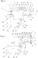
- eine schematische Darstellung eines ersten Ausführungsbeispiels einer erfindungsgemäßen Pumpenanordnung;
- Fig. 2
- eine schematische Darstellung eines zweiten Ausführungsbeispiels gemäß der Erfindung, und
- Fig. 3
- eine Darstellung eines beispielhaften Druckverlaufs im Antriebsfluidsystem gemäß
Fig. 1 beim Auftreten von Verschleiß bei einem der Einlassventile.
- Fig. 1
- a schematic representation of a first embodiment of a pump assembly according to the invention;
- Fig. 2
- a schematic representation of a second embodiment according to the invention, and
- Fig. 3
- a representation of an exemplary pressure profile in the drive fluid system according to
Fig. 1 when wear occurs on one of the intake valves.
In den
Im ersten Ausführungsbeispiel gemäß
Jedem Arbeitsraum 1, 2 ist jeweils ein Einlassventil 7 und ein Auslassventil 8 zugeordnet. Die Einlassventile 7 und Auslassventile 8 sind als federvorgespannte Rückschlagventile ausgeführt und an sich bekannt. Ist das zumindest eine Einlassventil 7 und/oder das zumindest eine Auslassventil 8 unversehrt, ist eine der Durchlassrichtungen für Flüssigkeit in einer Schließstellung gesperrt. In der gegenüberliegenden Durchlassrichtung kann Flüssigkeit durch das geöffnete Einlassventil 7 und/oder Auslassventil 8 strömen. Die schematisch dargestellten Ventilteller der Einlassventile 7 und Auslassventile 8 liegen somit in der Schließstellung federvorgespannt an einem korrespondierenden Ventilsitz an, vgl.
Die Einlassventile 7 sind mit einem Sauganschluss 9 der Pumpenanordnung fluidleitend verbunden. An den Sauganschluss 9 kann eine nicht näher dargestellte Saugleitung zur Aufnahme von Schmutzwasser oder allgemein von, insbesondere mit Schmutzpartikeln kontaminierter, Flüssigkeit angeschlossen werden kann. Die Auslassventile 8 sind mit einem Auslassanschluss 10 der Pumpenanordnung fluidleitendverbunden. Vom Auslassanschluss 10 weg könnte eine ebenfalls nicht näher dargestellte Leitung in einen, beispielsweise auf einem Kanalreinigungsfahrzeug angeordneten, Speicherbehälter für Schmutzwasser führen.The
Die Pumpenanordnung weist ein mit einem Antriebsfluid betreibbares Antriebsfluidsystem 20 auf. Als Antriebsfluid kann beispielsweise Hydrauliköl verwendet werden. Das Antriebsfluidsystem 20 ist in den hier gezeigten Ausführungsbeispielen als geschlossenes System ausgebildet, d.h. das Antriebsfluid wird in einem Kreislauf im Antriebsfluidsystem 22 befördert.The pump assembly includes a
Das Antriebsfluidsystem 20 weist eine volumengeregelte Antriebsfluidpumpe 27 auf, welche beispielsweise mittels eines Elektromotors 28 antreibbar ist. Anstatt eines Elektromotors könnte z.B. auch eine Verbrennungskraftmaschine, ein Hydraulikmotor oder dergleichen eingesetzt werden. Die hier im gezeigten Ausführungsbeispiel volumengeregelte Antriebsfluidpumpe 27 stellt einen, beispielsweise vom Benutzer mittels einer Steuereinrichtung 30 der Pumpenanordnung vorausgewählten, konstanten Volumenstrom zum Bewegen eines Antriebskolbens 21 bereit. Der Antriebskolben 21 ist in einem Antriebszylinder 22 des Antriebsfluidsystems 20 linear bewegbar gelagert. Der eine umlaufende Dichtung aufweisende Antriebskolben 21 trennt einen ersten Antriebsraum 23 und einen zweiten Antriebsraum 24 voneinander.The
Ein Umschaltventil 26 leitet das unter Druck stehende Antriebsfluid wechselweise dem ersten Antriebsraum 23 oder dem zweitem Antriebsraum 24 zu, während Antriebsfluid aus dem anderen der beiden Antriebsräume 23, 24 ausgestoßen und in einer Ölwanne 29 des Antriebsfluidsystems 20 gesammelt wird. Das in der Ölwanne 29 gesammelte Antriebsfluid kann im Weiteren wieder von der Antriebsfluidpumpe 27 angesaugt werden, womit der Kreislauf des Antriebsfluidsystems 20 geschlossen ist. Das Umschaltventil 26 des Antriebsfluidsystems 20 kann mittels der Steuereinrichtung 30 der Pumpenanordnung angesteuert werden.A switching
Die Pumpenanordnung gemäß
Die Förderkolben 3, 4 sind mit dem Antriebskolben 21 starr verbunden. Der Antriebskolben 21 ist in diesem Ausführungsbeispiel zwischen den Förderkolben 3, 4 angeordnet. Mit dieser Anordnung ist es möglich, eine kontinuierliche Förderung von Schmutzwasser von der Seite des Sauganschlusses 9 zur Seite des Auslassanschlusses 10 zu ermöglichen.The
Eine Bewegung des Förderkolbens 3, hervorgerufen durch die Bewegung des Antriebskolbens 21, in eine erste Bewegungsrichtung 31 führt zu einer Vergrößerung des Volumens des Arbeitsraums 1. Dabei wird Schmutzwasser über den Sauganschluss 9 durch das dem Arbeitsraum 1 zugeordnete Einlassventil 7 hindurch in den Arbeitsraum 1 eingesaugt. Der Ventilteller des Einlassventils 7 wird durch den im Arbeitsraum 1 entstehenden Unterdruck vom Ventilsitz abgehoben, wobei Flüssigkeit aus vom Sauganschluss 9 in den Arbeitsraum 1 strömt. Das dem ersten Arbeitsraum 1 zugeordnete Auslassventil 8 befindet sich bei einer Bewegung des Förderkolbens 3 in die erste Bewegungsrichtung 31 in der Schließstellung und verhindert, bei einem unversehrten Auslassventil 8, ein Rückströmen von Schmutzwasser über den Auslassanschluss 10 in den Arbeitsraum 1.A movement of the
Zeitgleich mit der Bewegung des Förderkolbens 3 erfolgt, aufgrund der starren Verbindung mit dem Antriebskolben 21, auch eine synchrone Bewegung des Förderkolbens 4 in die erste Bewegungsrichtung 31, wobei das Volumen des Arbeitsraums 2 verkleinert wird. Hierbei wird Schmutzwasser aus dem Arbeitsraum 2 durch das dem Arbeitsraum 2 zugeordnete Auslassventil 8 hindurch in Richtung hin zum Auslassanschluss 10 ausgestoßen. Das dem Arbeitsraum 2 zugeordnete Einlassventil 7 befindet sich bei einer Bewegung des Förderkolbens 3 in Bewegungsrichtung 31 in der Schließstellung und verhindert, bei einem unversehrten Einlassventil 7, ein Rückströmen von Schmutzwasser in Richtung hin zum Sauganschluss 9. Bei Erreichen einer, bezogen auf das in
Der erste Antriebsraum 23 und der zweite Antriebsraum 24 sind jeweils mittels einer Dichtung 16 gegenüber den, im Normalbetrieb mit Schmutzwasser gefüllten, Arbeitsräumen 1, 2 abgedichtet.The
Die Pumpenanordnung weist eine Verschleißüberwachungseinrichtung 40 zur Überwachung des Verschleißes des Einlassventils 7 und/oder des Auslassventils 8 auf. Hierzu ist ein Druckaufnehmer 41 der Verschleißüberwachungseinrichtung 40 zur Erfassung des Drucks des Antriebsfluids im Antriebsfluidsystem 20 angeordnet. Die vom Druckaufnehmer 41 ausgegebenen Druckmesswerte werden von einer Druckauswerteeinheit 42 verarbeitet. Der Druckaufnehmer 41 ist zwischen der Antriebsfluidpumpe 27 und dem Umschaltventil 26 angeordnet. Dadurch kann ein einziger Druckaufnehmer 41 zur Erfassung des Drucks des Antriebsfluides während der Bewegung des Antriebskolbens 21 in die erste Bewegungsrichtung 31 und zur Erfassung des Drucks des Antriebsfluides in die zweite Bewegungsrichtung 32 erfolgen. Durch die Anordnung des Druckaufnehmers 41 zwischen der Antriebsfluidpumpe 27 und dem Umschaltventil 26 kann auf einen zusätzlichen Druckaufnehmer 41 verzichtet werden. Es wäre in anderen Ausführungsformen auch denkbar und möglich, den Druck auch an einer anderen Stelle im Antriebsfluidsystem 20 zu messen, z. B. an der jeweiligen Verbindungsleitung zwischen dem ersten Antriebsraum 23 und dem Umschaltventil 26 und dem zweiten Antriebsraum 24 und dem Umschaltventil 26.The pump arrangement has a
Die Verschleißüberwachungseinrichtung 40 weist eine Meldeeinheit 44 zur akustischen und/oder visuellen Information eines Benutzers bei Vorliegen eines von der Druckauswerteeinheit 42 festgestellten Verschleißes des zumindest einen Einlassventils 7 und/oder des zumindest einen Auslassventils 8 auf.The
Tritt ein Verschleiß des zumindest einen Einlassventils 7 und/oder des zumindest einen Auslassventils 8 auf, so ist die zuverlässige Abdichtung des Ventiltellers gegenüber dem Ventilsitz in der Schließstellung nicht mehr gegeben. Hierbei kann es zu einem Rückströmen von Flüssigkeit durch das Einlassventil 7 oder das Auslassventil 8 kommen, wodurch die Leistung der Pumpenanordnung bzw. die Fördermenge je Zeiteinheit vermindert wird. Mit der Druckauswerteeinheit 42 kann der Verschleiß des zumindest einen Einlassventils 7 und/oder des zumindest einen Auslassventils 8 überwacht werden, da bei einem Rückströmen von Flüssigkeit, z.B. während des Verkleinerns des Volumens eines der Arbeitsräume 1, 2 über ein verschlissenes Einlassventil 7 aus dem betroffenen Arbeitsraum 1, 2 heraus, auch der Druckverlauf im Antriebsfluid beeinflusst wird.If wear of the at least one
Im Ausführungsbeispiel ist vorgesehen, dass neben vom Druckaufnehmer 41 ausgegebenen Druckmesswerten auch die Signal der Näherungsschalter 43, welche die Endlage der Förderkolben 3, 4 bzw. des Antriebskolbens 21 erfassen, von der Steuereinrichtung 30 an die Druckauswerteeinheit 42 übermittelt werden. Dadurch kann eine Zuordnung der gemessenen Druckmesswerte zu Hüben in die erste Bewegungsrichtung 31 und die zweite Bewegungsrichtung 32 erfolgen. Alternativ oder zusätzlich ist es auch möglich, dass der aktuelle Schaltzustand des Umschaltventils 26 von der Steuereinrichtung 30 an die Druckauswerteeinheit 42 übermittelt wird, um eine Zuordnung der Druckmesswerte zur aktuellen Bewegungsrichtung des Antriebskolbens 21 zu ermöglichen.In the exemplary embodiment, it is provided that, in addition to pressure readings issued by the
In
Der Druckverlauf 50 zu Beginn jeweils eines Hubs des Arbeitskolbens 21 in die erste und zweite Bewegungsrichtung 31, 32 weist ein markantes Tal 57 auf. Die eingezeichnete Zeitspanne 53 markiert den während eines Hubs des Arbeitskolbens 21 in die erste Bewegungsrichtung 31 aufgezeichneten Druckverlauf, während die Zeitspanne 54 den während eines Hubs des Arbeitskolbens 21 in die zweite Bewegungsrichtung 32 aufgezeichneten Druckverlauf markiert.The
Ausgehend von den während einer Abfolge von Hüben verarbeiteten Druckmesswerten wird ein Kennwert 51, 52 gebildet und der Unterschied der Kennwerte 51, 52 von aufeinanderfolgenden Hubvorgängen mit einem vorab definierten Schwellwert verglichen. Im Ausführungsbeispiel erfolgt die Ermittlung von mittleren Steigungslinien 55, 56 des Druckverlaufs 50 während einer jeweiligen Zeitspanne 53, 54. Die mittlere Steigungslinie 55, 56 wird durch die Druckauswerteeinheit 42 beispielsweise mittels einer Regressionsrechnung ermittelt. Extreme Ausschläge am Beginn oder am Ende eines jeweiligen Hubes können hierbei unberücksichtigt bleiben. Aus dem Steigungswert der Steigungslinie 55 wird ein erster Kennwert 51 gebildet. Für die Zeitspanne 54 wird als zweiter Kennwert 52 der Steigungswert der Steigungslinie 56 ermittelt.On the basis of the pressure measured values processed during a sequence of strokes, a
In Hinblick auf den in
Die Kennwerte 51, 52 werden im Ausführungsbeispiel aus mittleren Steigungslinien 55, 56 des Druckverlaufs 50 ermittelt. Es ist denkbar und möglich, auch andere Kennwerte zur Überwachung des Verschleißes des Einlassventils 7 und/oder des Auslassventils 8 heranzuziehen. Beispielsweise könnte ein während eines Hubs festgestellter maximaler Druck mit einem maximalen Druck eines darauf folgenden Hubs verglichen werden.The
Alternativ oder zusätzlich könnte auch vorgesehen sein, dass die Druckauswerteeinheit 42 aus verarbeiteten Druckmesswerten während eines Hubs des Antriebskolbens 21 einen Kennwert bildet, welcher mit einem Referenzwert verglichen wird. Der Referenzwert könnte beispielsweise bei der ersten Inbetriebnahme der Pumpenanordnung ermittelt und in der Druckauswerteeinheit 42 hinterlegt werden. Wie eingangs bereits erläutert, könnte dem Referenzwert auch ein Toleranzbereich zugeordnet werden. Es könnte in diesem Zusammenhang vorgesehen sein, dass erst dann auf ein Vorliegen von Verschleiß erkannt wird bzw. die oben genannte Information über das Vorliegen von Verschleiß an den Benutzer z.B. über die Meldeeinheit 44 abgegeben wird, wenn der ermittelte Kennwert außerhalb des den Referenzwert umgebenden Toleranzbereichs liegt.Alternatively or additionally, it could also be provided that the
In
Die Pumpenanordnung gemäß des zweiten Ausführungsbeispiels umfasst einen Förderkolben 13, welcher eine ortsfest am Förderkolben 13 angeordnete, umlaufende Dichtung 15 aufweist. Der Förderkolben 13 ist in einem Förderzylinder 14 linear bewegbar gelagert. Der Förderkolben 18 ist mittels einer Kolbenstange 18 mit dem Antriebskolben 21 starr verbunden. Die Pumpenanordnung weist zwei Arbeitsräume 11, 12 auf, wobei der Förderkolben 13 den ersten der Arbeitsräume 11 und den zweiten der Arbeitsräume 12 voneinander trennt. Jedem der Arbeitsräume 11, 12 ist ein Einlassventil 7 und ein Auslassventil 8 zugeordnet.The pump arrangement according to the second exemplary embodiment comprises a delivery piston 13, which has a
Bei einer Bewegung des Förderkolbens 13 in die Bewegungsrichtung 31 erfolgt eine Verkleinerung des Arbeitsraums 11, während gleichzeitig eine Vergrößerung des Volumens des Arbeitsraums 12 erfolgt. Die Dichtung 17 trennt den zweiten Arbeitsraum 12 und den zweiten Antriebsraum 24 des Antriebszylinders 22 voneinander. Die Bewegung des Antriebskolbens 21 erfolgt analog zum ersten Ausführungsbeispiel, wobei die Endlage des Antriebskolbens 21 direkt über die am Antriebszylinder 22 angeordneten Näherungsschalter 43 erfolgt.During a movement of the delivery piston 13 in the direction of
Im Ausführungsbeispiel gemäß
Claims (10)
Priority Applications (1)
| Application Number | Priority Date | Filing Date | Title |
|---|---|---|---|
| PL17156863T PL3246568T3 (en) | 2016-05-17 | 2017-02-20 | Pump assembly |
Applications Claiming Priority (1)
| Application Number | Priority Date | Filing Date | Title |
|---|---|---|---|
| ATA246/2016A AT518691B1 (en) | 2016-05-17 | 2016-05-17 | pump assembly |
Publications (2)
| Publication Number | Publication Date |
|---|---|
| EP3246568A1 true EP3246568A1 (en) | 2017-11-22 |
| EP3246568B1 EP3246568B1 (en) | 2019-08-14 |
Family
ID=58094292
Family Applications (1)
| Application Number | Title | Priority Date | Filing Date |
|---|---|---|---|
| EP17156863.7A Active EP3246568B1 (en) | 2016-05-17 | 2017-02-20 | Pump assembly |
Country Status (4)
| Country | Link |
|---|---|
| US (1) | US20170335840A1 (en) |
| EP (1) | EP3246568B1 (en) |
| AT (1) | AT518691B1 (en) |
| PL (1) | PL3246568T3 (en) |
Families Citing this family (3)
| Publication number | Priority date | Publication date | Assignee | Title |
|---|---|---|---|---|
| US10443586B1 (en) * | 2018-09-12 | 2019-10-15 | Douglas A Sahm | Fluid transfer and depressurization system |
| DE102019104887A1 (en) * | 2019-02-26 | 2020-08-27 | Liebherr-Werk Nenzing Gmbh | Wear monitoring system for an overburden pump and method for wear monitoring of an overburden pump |
| DE102019133576B3 (en) * | 2019-12-09 | 2020-12-17 | Maximator Gmbh | Compressor and method for conveying and compressing a conveying fluid in a target system |
Citations (6)
| Publication number | Priority date | Publication date | Assignee | Title |
|---|---|---|---|---|
| EP0448906A2 (en) * | 1990-03-14 | 1991-10-02 | Tc/American Monorail, Inc. | Intensifier |
| US5094596A (en) * | 1990-06-01 | 1992-03-10 | Binks Manufacturing Company | High pressure piston pump for fluent materials |
| US5415531A (en) * | 1994-04-06 | 1995-05-16 | Binks Manufacturing Company | Piston pump for fluent materials |
| US20070286745A1 (en) * | 2006-06-09 | 2007-12-13 | Maynard Chance | Integrated mixing pump |
| US20120063939A1 (en) * | 2010-09-10 | 2012-03-15 | Mann Michael D | High pressure pump including hollow stud |
| US20140199182A1 (en) * | 2013-01-11 | 2014-07-17 | Super Products Llc | Reciprocating water pump |
Family Cites Families (33)
| Publication number | Priority date | Publication date | Assignee | Title |
|---|---|---|---|---|
| DE1577188A1 (en) * | 1966-01-13 | 1969-09-25 | Stahl Und Appbau Hans Leffer G | Hydraulic pressure generation system with double-acting pressure intensifier |
| US4309152A (en) * | 1979-09-06 | 1982-01-05 | Sea Energy Corporation | Hydraulic motor/pump with variable mechanical advantage |
| US4630441A (en) * | 1984-09-04 | 1986-12-23 | The Boeing Company | Electrohydraulic actuator for aircraft control surfaces |
| US5587525A (en) * | 1992-06-19 | 1996-12-24 | Western Atlas International, Inc. | Formation fluid flow rate determination method and apparatus for electric wireline formation testing tools |
| US5527204A (en) * | 1993-08-27 | 1996-06-18 | Rhoades; Lawrence J. | Abrasive jet stream cutting |
| JP4021479B2 (en) * | 1995-05-16 | 2007-12-12 | グローブマグ・リミテッド・パートナーシップ | Device with at least one hydraulic shaft |
| US5778671A (en) * | 1996-09-13 | 1998-07-14 | Vickers, Inc. | Electrohydraulic system and apparatus with bidirectional electric-motor/hydraulic-pump unit |
| US6068448A (en) * | 1996-12-09 | 2000-05-30 | Sugino Machine Limited | Pressure hydraulic pump having first and second synchronously driven reciprocating pistons with a pressure control structure |
| US5879137A (en) * | 1997-01-22 | 1999-03-09 | Jetec Corporation | Method and apparatus for pressurizing fluids |
| US6135719A (en) * | 1997-12-29 | 2000-10-24 | Oilquip, Inc. | Method and apparatus for metering injection pump flow |
| AT405981B (en) * | 1998-07-31 | 2000-01-25 | Hoerbiger Ventilwerke Gmbh | WEAR MONITOR |
| AT412672B (en) * | 2002-10-30 | 2005-05-25 | Hoerbiger Kompressortech Hold | MONITOR FOR MONITORING THE MOVEMENT TRACK OF A PISTON |
| US7056097B2 (en) * | 2003-07-30 | 2006-06-06 | Equistar Chemicals L.P. | System and method for monitoring the mechanical condition of a reciprocating compressor |
| US7124819B2 (en) * | 2003-12-01 | 2006-10-24 | Schlumberger Technology Corporation | Downhole fluid pumping apparatus and method |
| US9147893B2 (en) * | 2004-06-02 | 2015-09-29 | Toyota Jidosha Kabushiki Kaisha | Failure diagnostic device for discharge valve |
| US20060163774A1 (en) * | 2005-01-25 | 2006-07-27 | Norbert Abels | Methods for shaping green bodies and articles made by such methods |
| DE102005035171A1 (en) * | 2005-07-27 | 2007-02-01 | Bosch Rexroth Aktiengesellschaft | Electrohydraulic steering |
| US8366402B2 (en) * | 2005-12-20 | 2013-02-05 | Schlumberger Technology Corporation | System and method for determining onset of failure modes in a positive displacement pump |
| DE102006001585A1 (en) * | 2006-01-12 | 2007-07-19 | Rehau Ag + Co. | Method for monitoring the wear of pumps and pump for carrying out the method |
| GB2454908B (en) * | 2007-11-23 | 2012-04-11 | Schlumberger Holdings | Hydraulic manifold pump |
| US8720197B2 (en) * | 2008-02-12 | 2014-05-13 | Parker-Hannifin Corporation | Flow management system for hydraulic work machine |
| WO2010028100A1 (en) * | 2008-09-03 | 2010-03-11 | Parker Hannifin Corporation | Velocity control of unbalanced hydraulic actuator subjected to over-center load conditions |
| US20100106458A1 (en) * | 2008-10-28 | 2010-04-29 | Leu Ming C | Computer program and method for detecting and predicting valve failure in a reciprocating compressor |
| US8708042B2 (en) * | 2010-02-17 | 2014-04-29 | Baker Hughes Incorporated | Apparatus and method for valve actuation |
| AR086188A1 (en) * | 2011-04-20 | 2013-11-27 | Spm Flow Control Inc | AN ALTERNATIVE PUMP |
| US8757986B2 (en) * | 2011-07-18 | 2014-06-24 | Schlumberger Technology Corporation | Adaptive pump control for positive displacement pump failure modes |
| US8984930B2 (en) * | 2011-09-15 | 2015-03-24 | General Electric Company | System and method for diagnosing a reciprocating compressor |
| AT512322B1 (en) * | 2011-12-30 | 2013-09-15 | Bhdt Gmbh | HYDRAULIC DRIVE FOR A PRESSURE TRANSLATOR |
| US9144882B2 (en) * | 2012-04-04 | 2015-09-29 | Hypertherm, Inc. | Identifying liquid jet cutting system components |
| WO2014074708A1 (en) * | 2012-11-07 | 2014-05-15 | Parker-Hannifin Corporation | Electro-hydrostatic actuator deceleration rate control system |
| US9695840B2 (en) * | 2013-08-20 | 2017-07-04 | Vianney Rabhi | Reversible hydraulic pressure converter employing tubular valves |
| US9464399B2 (en) * | 2014-01-28 | 2016-10-11 | Ats Smart Solutions, Llc | Pile cutter |
| AT515937B1 (en) * | 2014-10-20 | 2016-01-15 | Bhdt Gmbh | Hydraulic drive for a pressure intensifier |
-
2016
- 2016-05-17 AT ATA246/2016A patent/AT518691B1/en not_active IP Right Cessation
-
2017
- 2017-02-20 PL PL17156863T patent/PL3246568T3/en unknown
- 2017-02-20 EP EP17156863.7A patent/EP3246568B1/en active Active
- 2017-04-12 US US15/485,758 patent/US20170335840A1/en not_active Abandoned
Patent Citations (6)
| Publication number | Priority date | Publication date | Assignee | Title |
|---|---|---|---|---|
| EP0448906A2 (en) * | 1990-03-14 | 1991-10-02 | Tc/American Monorail, Inc. | Intensifier |
| US5094596A (en) * | 1990-06-01 | 1992-03-10 | Binks Manufacturing Company | High pressure piston pump for fluent materials |
| US5415531A (en) * | 1994-04-06 | 1995-05-16 | Binks Manufacturing Company | Piston pump for fluent materials |
| US20070286745A1 (en) * | 2006-06-09 | 2007-12-13 | Maynard Chance | Integrated mixing pump |
| US20120063939A1 (en) * | 2010-09-10 | 2012-03-15 | Mann Michael D | High pressure pump including hollow stud |
| US20140199182A1 (en) * | 2013-01-11 | 2014-07-17 | Super Products Llc | Reciprocating water pump |
Also Published As
| Publication number | Publication date |
|---|---|
| AT518691B1 (en) | 2018-04-15 |
| PL3246568T3 (en) | 2020-02-28 |
| AT518691A1 (en) | 2017-12-15 |
| EP3246568B1 (en) | 2019-08-14 |
| US20170335840A1 (en) | 2017-11-23 |
Similar Documents
| Publication | Publication Date | Title |
|---|---|---|
| EP3246568B1 (en) | Pump assembly | |
| EP1727980B1 (en) | Device and method for controlling a two-cylinder thick matter pump | |
| EP2356339B1 (en) | Clamping device for cylinder bush and its use and flushing pump with a clamping device | |
| EP2085614B1 (en) | Pumping device, in particular double diaphragm pump driven by a piston pump | |
| DE10036202A1 (en) | Slurry pump | |
| EP3158193B1 (en) | Device and method for dampening pressure pulsations within the discharge piping of a pump for viscuous fluids | |
| DE19826610A1 (en) | Diaphragm pump and device for controlling the same | |
| DE102016201208B4 (en) | Piston compressor with ventilation device | |
| EP2337676A1 (en) | Hydraulic press drive and a method for operating a hydraulic press drive | |
| WO2018091306A1 (en) | Method for operating a piston pump, and piston pump | |
| DE102009038676B4 (en) | Oil circuit for an internal combustion engine | |
| EP2638288A1 (en) | Method and system for identifying damage to piston membrane pumps containing working fluids | |
| EP1400313B1 (en) | Hydraulically operated ratchet spanner with a double-acting hydraulic cylinder/piston drive | |
| EP3441612B1 (en) | Pumping unit, storage device equipped with the same and method for operating said storage device | |
| DE102016119930A1 (en) | Positive displacement pump with adjustable stop surface | |
| EP3119596B1 (en) | Device for sealing and inflating inflatable articles | |
| WO2015078487A1 (en) | Metering and delivery pump for chemically aggressive and/or abrasive fluids | |
| WO2022223404A1 (en) | Conveying device | |
| DE3206613A1 (en) | Pressure-increasing piston pump | |
| EP2918835B1 (en) | Diaphragm pump | |
| EP3409943B1 (en) | Plunger pump and use of a plunger pump | |
| EP3599377B1 (en) | Method for determining a volume transported by means of a piston pump and double-acting, pneumatically driven piston pump for carrying out the method | |
| DE102008014340B4 (en) | Barrel Follower pump | |
| WO2016045841A1 (en) | Pumping device, especially axial piston pump, for a waste heat recovery apparatus in a motor vehicle | |
| EP3167191B1 (en) | Diaphragm pump with reduced leak extension in the event of overload |
Legal Events
| Date | Code | Title | Description |
|---|---|---|---|
| PUAI | Public reference made under article 153(3) epc to a published international application that has entered the european phase |
Free format text: ORIGINAL CODE: 0009012 |
|
| STAA | Information on the status of an ep patent application or granted ep patent |
Free format text: STATUS: THE APPLICATION HAS BEEN PUBLISHED |
|
| AK | Designated contracting states |
Kind code of ref document: A1 Designated state(s): AL AT BE BG CH CY CZ DE DK EE ES FI FR GB GR HR HU IE IS IT LI LT LU LV MC MK MT NL NO PL PT RO RS SE SI SK SM TR |
|
| AX | Request for extension of the european patent |
Extension state: BA ME |
|
| STAA | Information on the status of an ep patent application or granted ep patent |
Free format text: STATUS: REQUEST FOR EXAMINATION WAS MADE |
|
| 17P | Request for examination filed |
Effective date: 20180424 |
|
| RBV | Designated contracting states (corrected) |
Designated state(s): AL AT BE BG CH CY CZ DE DK EE ES FI FR GB GR HR HU IE IS IT LI LT LU LV MC MK MT NL NO PL PT RO RS SE SI SK SM TR |
|
| GRAP | Despatch of communication of intention to grant a patent |
Free format text: ORIGINAL CODE: EPIDOSNIGR1 |
|
| STAA | Information on the status of an ep patent application or granted ep patent |
Free format text: STATUS: GRANT OF PATENT IS INTENDED |
|
| INTG | Intention to grant announced |
Effective date: 20190509 |
|
| GRAS | Grant fee paid |
Free format text: ORIGINAL CODE: EPIDOSNIGR3 |
|
| GRAA | (expected) grant |
Free format text: ORIGINAL CODE: 0009210 |
|
| STAA | Information on the status of an ep patent application or granted ep patent |
Free format text: STATUS: THE PATENT HAS BEEN GRANTED |
|
| AK | Designated contracting states |
Kind code of ref document: B1 Designated state(s): AL AT BE BG CH CY CZ DE DK EE ES FI FR GB GR HR HU IE IS IT LI LT LU LV MC MK MT NL NO PL PT RO RS SE SI SK SM TR |
|
| REG | Reference to a national code |
Ref country code: GB Ref legal event code: FG4D Free format text: NOT ENGLISH |
|
| REG | Reference to a national code |
Ref country code: CH Ref legal event code: EP Ref country code: AT Ref legal event code: REF Ref document number: 1167343 Country of ref document: AT Kind code of ref document: T Effective date: 20190815 |
|
| REG | Reference to a national code |
Ref country code: IE Ref legal event code: FG4D Free format text: LANGUAGE OF EP DOCUMENT: GERMAN |
|
| REG | Reference to a national code |
Ref country code: DE Ref legal event code: R096 Ref document number: 502017002004 Country of ref document: DE |
|
| REG | Reference to a national code |
Ref country code: CH Ref legal event code: NV Representative=s name: SCHNEIDER FELDMANN AG PATENT- UND MARKENANWAEL, CH |
|
| REG | Reference to a national code |
Ref country code: SE Ref legal event code: TRGR |
|
| REG | Reference to a national code |
Ref country code: NL Ref legal event code: MP Effective date: 20190814 |
|
| REG | Reference to a national code |
Ref country code: LT Ref legal event code: MG4D |
|
| PG25 | Lapsed in a contracting state [announced via postgrant information from national office to epo] |
Ref country code: BG Free format text: LAPSE BECAUSE OF FAILURE TO SUBMIT A TRANSLATION OF THE DESCRIPTION OR TO PAY THE FEE WITHIN THE PRESCRIBED TIME-LIMIT Effective date: 20191114 Ref country code: NO Free format text: LAPSE BECAUSE OF FAILURE TO SUBMIT A TRANSLATION OF THE DESCRIPTION OR TO PAY THE FEE WITHIN THE PRESCRIBED TIME-LIMIT Effective date: 20191114 Ref country code: PT Free format text: LAPSE BECAUSE OF FAILURE TO SUBMIT A TRANSLATION OF THE DESCRIPTION OR TO PAY THE FEE WITHIN THE PRESCRIBED TIME-LIMIT Effective date: 20191216 Ref country code: HR Free format text: LAPSE BECAUSE OF FAILURE TO SUBMIT A TRANSLATION OF THE DESCRIPTION OR TO PAY THE FEE WITHIN THE PRESCRIBED TIME-LIMIT Effective date: 20190814 Ref country code: NL Free format text: LAPSE BECAUSE OF FAILURE TO SUBMIT A TRANSLATION OF THE DESCRIPTION OR TO PAY THE FEE WITHIN THE PRESCRIBED TIME-LIMIT Effective date: 20190814 Ref country code: LT Free format text: LAPSE BECAUSE OF FAILURE TO SUBMIT A TRANSLATION OF THE DESCRIPTION OR TO PAY THE FEE WITHIN THE PRESCRIBED TIME-LIMIT Effective date: 20190814 |
|
| PG25 | Lapsed in a contracting state [announced via postgrant information from national office to epo] |
Ref country code: GR Free format text: LAPSE BECAUSE OF FAILURE TO SUBMIT A TRANSLATION OF THE DESCRIPTION OR TO PAY THE FEE WITHIN THE PRESCRIBED TIME-LIMIT Effective date: 20191115 Ref country code: RS Free format text: LAPSE BECAUSE OF FAILURE TO SUBMIT A TRANSLATION OF THE DESCRIPTION OR TO PAY THE FEE WITHIN THE PRESCRIBED TIME-LIMIT Effective date: 20190814 Ref country code: ES Free format text: LAPSE BECAUSE OF FAILURE TO SUBMIT A TRANSLATION OF THE DESCRIPTION OR TO PAY THE FEE WITHIN THE PRESCRIBED TIME-LIMIT Effective date: 20190814 Ref country code: IS Free format text: LAPSE BECAUSE OF FAILURE TO SUBMIT A TRANSLATION OF THE DESCRIPTION OR TO PAY THE FEE WITHIN THE PRESCRIBED TIME-LIMIT Effective date: 20191214 Ref country code: AL Free format text: LAPSE BECAUSE OF FAILURE TO SUBMIT A TRANSLATION OF THE DESCRIPTION OR TO PAY THE FEE WITHIN THE PRESCRIBED TIME-LIMIT Effective date: 20190814 Ref country code: LV Free format text: LAPSE BECAUSE OF FAILURE TO SUBMIT A TRANSLATION OF THE DESCRIPTION OR TO PAY THE FEE WITHIN THE PRESCRIBED TIME-LIMIT Effective date: 20190814 |
|
| PG25 | Lapsed in a contracting state [announced via postgrant information from national office to epo] |
Ref country code: TR Free format text: LAPSE BECAUSE OF FAILURE TO SUBMIT A TRANSLATION OF THE DESCRIPTION OR TO PAY THE FEE WITHIN THE PRESCRIBED TIME-LIMIT Effective date: 20190814 |
|
| PG25 | Lapsed in a contracting state [announced via postgrant information from national office to epo] |
Ref country code: DK Free format text: LAPSE BECAUSE OF FAILURE TO SUBMIT A TRANSLATION OF THE DESCRIPTION OR TO PAY THE FEE WITHIN THE PRESCRIBED TIME-LIMIT Effective date: 20190814 Ref country code: EE Free format text: LAPSE BECAUSE OF FAILURE TO SUBMIT A TRANSLATION OF THE DESCRIPTION OR TO PAY THE FEE WITHIN THE PRESCRIBED TIME-LIMIT Effective date: 20190814 Ref country code: RO Free format text: LAPSE BECAUSE OF FAILURE TO SUBMIT A TRANSLATION OF THE DESCRIPTION OR TO PAY THE FEE WITHIN THE PRESCRIBED TIME-LIMIT Effective date: 20190814 |
|
| PG25 | Lapsed in a contracting state [announced via postgrant information from national office to epo] |
Ref country code: IS Free format text: LAPSE BECAUSE OF FAILURE TO SUBMIT A TRANSLATION OF THE DESCRIPTION OR TO PAY THE FEE WITHIN THE PRESCRIBED TIME-LIMIT Effective date: 20200224 Ref country code: SK Free format text: LAPSE BECAUSE OF FAILURE TO SUBMIT A TRANSLATION OF THE DESCRIPTION OR TO PAY THE FEE WITHIN THE PRESCRIBED TIME-LIMIT Effective date: 20190814 Ref country code: CZ Free format text: LAPSE BECAUSE OF FAILURE TO SUBMIT A TRANSLATION OF THE DESCRIPTION OR TO PAY THE FEE WITHIN THE PRESCRIBED TIME-LIMIT Effective date: 20190814 Ref country code: SM Free format text: LAPSE BECAUSE OF FAILURE TO SUBMIT A TRANSLATION OF THE DESCRIPTION OR TO PAY THE FEE WITHIN THE PRESCRIBED TIME-LIMIT Effective date: 20190814 |
|
| REG | Reference to a national code |
Ref country code: DE Ref legal event code: R097 Ref document number: 502017002004 Country of ref document: DE |
|
| PLBE | No opposition filed within time limit |
Free format text: ORIGINAL CODE: 0009261 |
|
| STAA | Information on the status of an ep patent application or granted ep patent |
Free format text: STATUS: NO OPPOSITION FILED WITHIN TIME LIMIT |
|
| PG2D | Information on lapse in contracting state deleted |
Ref country code: IS |
|
| 26N | No opposition filed |
Effective date: 20200603 |
|
| PG25 | Lapsed in a contracting state [announced via postgrant information from national office to epo] |
Ref country code: SI Free format text: LAPSE BECAUSE OF FAILURE TO SUBMIT A TRANSLATION OF THE DESCRIPTION OR TO PAY THE FEE WITHIN THE PRESCRIBED TIME-LIMIT Effective date: 20190814 |
|
| REG | Reference to a national code |
Ref country code: CH Ref legal event code: PFA Owner name: KAISER AKTIENGESELLSCHAFT, LI Free format text: FORMER OWNER: KAISER AKTIENGESELLSCHAFT, LI |
|
| REG | Reference to a national code |
Ref country code: BE Ref legal event code: MM Effective date: 20200229 |
|
| PG25 | Lapsed in a contracting state [announced via postgrant information from national office to epo] |
Ref country code: LU Free format text: LAPSE BECAUSE OF NON-PAYMENT OF DUE FEES Effective date: 20200220 Ref country code: MC Free format text: LAPSE BECAUSE OF FAILURE TO SUBMIT A TRANSLATION OF THE DESCRIPTION OR TO PAY THE FEE WITHIN THE PRESCRIBED TIME-LIMIT Effective date: 20190814 |
|
| PG25 | Lapsed in a contracting state [announced via postgrant information from national office to epo] |
Ref country code: IE Free format text: LAPSE BECAUSE OF NON-PAYMENT OF DUE FEES Effective date: 20200220 |
|
| PG25 | Lapsed in a contracting state [announced via postgrant information from national office to epo] |
Ref country code: BE Free format text: LAPSE BECAUSE OF NON-PAYMENT OF DUE FEES Effective date: 20200229 |
|
| PG25 | Lapsed in a contracting state [announced via postgrant information from national office to epo] |
Ref country code: MT Free format text: LAPSE BECAUSE OF FAILURE TO SUBMIT A TRANSLATION OF THE DESCRIPTION OR TO PAY THE FEE WITHIN THE PRESCRIBED TIME-LIMIT Effective date: 20190814 Ref country code: CY Free format text: LAPSE BECAUSE OF FAILURE TO SUBMIT A TRANSLATION OF THE DESCRIPTION OR TO PAY THE FEE WITHIN THE PRESCRIBED TIME-LIMIT Effective date: 20190814 |
|
| PG25 | Lapsed in a contracting state [announced via postgrant information from national office to epo] |
Ref country code: MK Free format text: LAPSE BECAUSE OF FAILURE TO SUBMIT A TRANSLATION OF THE DESCRIPTION OR TO PAY THE FEE WITHIN THE PRESCRIBED TIME-LIMIT Effective date: 20190814 |
|
| PGFP | Annual fee paid to national office [announced via postgrant information from national office to epo] |
Ref country code: FR Payment date: 20230223 Year of fee payment: 7 Ref country code: FI Payment date: 20230223 Year of fee payment: 7 Ref country code: CH Payment date: 20230307 Year of fee payment: 7 Ref country code: AT Payment date: 20230208 Year of fee payment: 7 |
|
| PGFP | Annual fee paid to national office [announced via postgrant information from national office to epo] |
Ref country code: SE Payment date: 20230222 Year of fee payment: 7 Ref country code: PL Payment date: 20230210 Year of fee payment: 7 Ref country code: IT Payment date: 20230220 Year of fee payment: 7 Ref country code: GB Payment date: 20230214 Year of fee payment: 7 Ref country code: DE Payment date: 20230227 Year of fee payment: 7 |
|
| PGFP | Annual fee paid to national office [announced via postgrant information from national office to epo] |
Ref country code: AT Payment date: 20240221 Year of fee payment: 8 |