EP3598539A1 - Elektrodenkörper für bleiakkumulator und denselben verwendender bleiakkumulator - Google Patents
Elektrodenkörper für bleiakkumulator und denselben verwendender bleiakkumulator Download PDFInfo
- Publication number
- EP3598539A1 EP3598539A1 EP18887921.7A EP18887921A EP3598539A1 EP 3598539 A1 EP3598539 A1 EP 3598539A1 EP 18887921 A EP18887921 A EP 18887921A EP 3598539 A1 EP3598539 A1 EP 3598539A1
- Authority
- EP
- European Patent Office
- Prior art keywords
- lead
- plating layer
- plating
- electrode plate
- acid battery
- Prior art date
- Legal status (The legal status is an assumption and is not a legal conclusion. Google has not performed a legal analysis and makes no representation as to the accuracy of the status listed.)
- Withdrawn
Links
- 238000003860 storage Methods 0.000 title description 6
- 238000007747 plating Methods 0.000 claims abstract description 401
- 239000002253 acid Substances 0.000 claims abstract description 87
- 229910000679 solder Inorganic materials 0.000 claims abstract description 70
- 229910052782 aluminium Inorganic materials 0.000 claims abstract description 63
- XAGFODPZIPBFFR-UHFFFAOYSA-N aluminium Chemical compound [Al] XAGFODPZIPBFFR-UHFFFAOYSA-N 0.000 claims abstract description 63
- 239000011149 active material Substances 0.000 claims abstract description 50
- 229910000838 Al alloy Inorganic materials 0.000 claims abstract description 27
- ATJFFYVFTNAWJD-UHFFFAOYSA-N Tin Chemical compound [Sn] ATJFFYVFTNAWJD-UHFFFAOYSA-N 0.000 claims description 54
- 230000015572 biosynthetic process Effects 0.000 abstract description 34
- 238000007599 discharging Methods 0.000 abstract description 33
- 239000002184 metal Substances 0.000 abstract description 31
- 229910052751 metal Inorganic materials 0.000 abstract description 30
- 239000000126 substance Substances 0.000 abstract description 10
- 238000012545 processing Methods 0.000 abstract description 6
- 150000002739 metals Chemical class 0.000 abstract description 5
- 239000010410 layer Substances 0.000 description 318
- QAOWNCQODCNURD-UHFFFAOYSA-N Sulfuric acid Chemical compound OS(O)(=O)=O QAOWNCQODCNURD-UHFFFAOYSA-N 0.000 description 88
- 239000010408 film Substances 0.000 description 78
- PXHVJJICTQNCMI-UHFFFAOYSA-N Nickel Chemical compound [Ni] PXHVJJICTQNCMI-UHFFFAOYSA-N 0.000 description 48
- 229910000978 Pb alloy Inorganic materials 0.000 description 45
- 238000000034 method Methods 0.000 description 39
- 239000000203 mixture Substances 0.000 description 25
- 229910052759 nickel Inorganic materials 0.000 description 23
- 238000004519 manufacturing process Methods 0.000 description 22
- 239000013585 weight reducing agent Substances 0.000 description 22
- 230000000052 comparative effect Effects 0.000 description 19
- 239000007773 negative electrode material Substances 0.000 description 19
- 239000007774 positive electrode material Substances 0.000 description 19
- 230000009467 reduction Effects 0.000 description 19
- 230000005484 gravity Effects 0.000 description 18
- WABPQHHGFIMREM-UHFFFAOYSA-N lead(0) Chemical compound [Pb] WABPQHHGFIMREM-UHFFFAOYSA-N 0.000 description 15
- 239000007788 liquid Substances 0.000 description 14
- 230000006872 improvement Effects 0.000 description 12
- 238000012360 testing method Methods 0.000 description 12
- 230000007797 corrosion Effects 0.000 description 9
- 238000005260 corrosion Methods 0.000 description 9
- 239000000956 alloy Substances 0.000 description 8
- 238000007796 conventional method Methods 0.000 description 8
- 239000000463 material Substances 0.000 description 8
- 238000004070 electrodeposition Methods 0.000 description 7
- 238000005868 electrolysis reaction Methods 0.000 description 7
- 230000008569 process Effects 0.000 description 7
- 230000000694 effects Effects 0.000 description 6
- 238000004898 kneading Methods 0.000 description 6
- 238000010030 laminating Methods 0.000 description 6
- 230000003746 surface roughness Effects 0.000 description 6
- XLYOFNOQVPJJNP-UHFFFAOYSA-N water Substances O XLYOFNOQVPJJNP-UHFFFAOYSA-N 0.000 description 6
- 108010010803 Gelatin Proteins 0.000 description 5
- 239000001888 Peptone Substances 0.000 description 5
- 108010080698 Peptones Proteins 0.000 description 5
- 238000013461 design Methods 0.000 description 5
- 229920000159 gelatin Polymers 0.000 description 5
- 239000008273 gelatin Substances 0.000 description 5
- 235000019322 gelatine Nutrition 0.000 description 5
- 235000011852 gelatine desserts Nutrition 0.000 description 5
- 239000006259 organic additive Substances 0.000 description 5
- 239000002245 particle Substances 0.000 description 5
- 235000019319 peptone Nutrition 0.000 description 5
- 238000002360 preparation method Methods 0.000 description 5
- 239000003981 vehicle Substances 0.000 description 5
- 239000013078 crystal Substances 0.000 description 4
- 238000001035 drying Methods 0.000 description 4
- 229910001174 tin-lead alloy Inorganic materials 0.000 description 4
- RILZRCJGXSFXNE-UHFFFAOYSA-N 2-[4-(trifluoromethoxy)phenyl]ethanol Chemical compound OCCC1=CC=C(OC(F)(F)F)C=C1 RILZRCJGXSFXNE-UHFFFAOYSA-N 0.000 description 3
- 229910001128 Sn alloy Inorganic materials 0.000 description 3
- QAOWNCQODCNURD-UHFFFAOYSA-L Sulfate Chemical compound [O-]S([O-])(=O)=O QAOWNCQODCNURD-UHFFFAOYSA-L 0.000 description 3
- 229910045601 alloy Inorganic materials 0.000 description 3
- 238000011161 development Methods 0.000 description 3
- 239000003792 electrolyte Substances 0.000 description 3
- 239000008151 electrolyte solution Substances 0.000 description 3
- 239000000835 fiber Substances 0.000 description 3
- 229940104869 fluorosilicate Drugs 0.000 description 3
- 239000000446 fuel Substances 0.000 description 3
- 230000020169 heat generation Effects 0.000 description 3
- 229910000464 lead oxide Inorganic materials 0.000 description 3
- 239000003595 mist Substances 0.000 description 3
- 150000007524 organic acids Chemical class 0.000 description 3
- YEXPOXQUZXUXJW-UHFFFAOYSA-N oxolead Chemical compound [Pb]=O YEXPOXQUZXUXJW-UHFFFAOYSA-N 0.000 description 3
- 229910001111 Fine metal Inorganic materials 0.000 description 2
- 238000002048 anodisation reaction Methods 0.000 description 2
- 230000008859 change Effects 0.000 description 2
- 239000003795 chemical substances by application Substances 0.000 description 2
- 238000004140 cleaning Methods 0.000 description 2
- 230000007613 environmental effect Effects 0.000 description 2
- 150000002611 lead compounds Chemical class 0.000 description 2
- LQBJWKCYZGMFEV-UHFFFAOYSA-N lead tin Chemical compound [Sn].[Pb] LQBJWKCYZGMFEV-UHFFFAOYSA-N 0.000 description 2
- 229910001092 metal group alloy Inorganic materials 0.000 description 2
- 229910000652 nickel hydride Inorganic materials 0.000 description 2
- 230000002093 peripheral effect Effects 0.000 description 2
- 238000007517 polishing process Methods 0.000 description 2
- 239000000843 powder Substances 0.000 description 2
- 230000002265 prevention Effects 0.000 description 2
- 238000004064 recycling Methods 0.000 description 2
- 230000002787 reinforcement Effects 0.000 description 2
- 238000005549 size reduction Methods 0.000 description 2
- 238000006467 substitution reaction Methods 0.000 description 2
- 239000000758 substrate Substances 0.000 description 2
- OKTJSMMVPCPJKN-UHFFFAOYSA-N Carbon Chemical compound [C] OKTJSMMVPCPJKN-UHFFFAOYSA-N 0.000 description 1
- RYGMFSIKBFXOCR-UHFFFAOYSA-N Copper Chemical compound [Cu] RYGMFSIKBFXOCR-UHFFFAOYSA-N 0.000 description 1
- HBBGRARXTFLTSG-UHFFFAOYSA-N Lithium ion Chemical compound [Li+] HBBGRARXTFLTSG-UHFFFAOYSA-N 0.000 description 1
- FYYHWMGAXLPEAU-UHFFFAOYSA-N Magnesium Chemical compound [Mg] FYYHWMGAXLPEAU-UHFFFAOYSA-N 0.000 description 1
- 235000019483 Peanut oil Nutrition 0.000 description 1
- 229910001245 Sb alloy Inorganic materials 0.000 description 1
- BQCADISMDOOEFD-UHFFFAOYSA-N Silver Chemical compound [Ag] BQCADISMDOOEFD-UHFFFAOYSA-N 0.000 description 1
- 239000002140 antimony alloy Substances 0.000 description 1
- 229910052802 copper Inorganic materials 0.000 description 1
- 239000010949 copper Substances 0.000 description 1
- 238000005536 corrosion prevention Methods 0.000 description 1
- 230000007423 decrease Effects 0.000 description 1
- 230000007547 defect Effects 0.000 description 1
- 238000010790 dilution Methods 0.000 description 1
- 239000012895 dilution Substances 0.000 description 1
- 238000011038 discontinuous diafiltration by volume reduction Methods 0.000 description 1
- 239000000428 dust Substances 0.000 description 1
- 239000003365 glass fiber Substances 0.000 description 1
- PCHJSUWPFVWCPO-UHFFFAOYSA-N gold Chemical compound [Au] PCHJSUWPFVWCPO-UHFFFAOYSA-N 0.000 description 1
- 229910052737 gold Inorganic materials 0.000 description 1
- 239000010931 gold Substances 0.000 description 1
- 229910002804 graphite Inorganic materials 0.000 description 1
- 239000010439 graphite Substances 0.000 description 1
- 229910001416 lithium ion Inorganic materials 0.000 description 1
- 229910052749 magnesium Inorganic materials 0.000 description 1
- 239000011777 magnesium Substances 0.000 description 1
- 230000007246 mechanism Effects 0.000 description 1
- VNWKTOKETHGBQD-UHFFFAOYSA-N methane Chemical compound C VNWKTOKETHGBQD-UHFFFAOYSA-N 0.000 description 1
- TWNQGVIAIRXVLR-UHFFFAOYSA-N oxo(oxoalumanyloxy)alumane Chemical compound O=[Al]O[Al]=O TWNQGVIAIRXVLR-UHFFFAOYSA-N 0.000 description 1
- 239000000312 peanut oil Substances 0.000 description 1
- 230000000149 penetrating effect Effects 0.000 description 1
- 229940044652 phenolsulfonate Drugs 0.000 description 1
- 239000004033 plastic Substances 0.000 description 1
- 238000011160 research Methods 0.000 description 1
- 239000011347 resin Substances 0.000 description 1
- 229920005989 resin Polymers 0.000 description 1
- 229910052709 silver Inorganic materials 0.000 description 1
- 239000004332 silver Substances 0.000 description 1
- 239000002356 single layer Substances 0.000 description 1
- 239000007779 soft material Substances 0.000 description 1
- 239000000243 solution Substances 0.000 description 1
- 239000007921 spray Substances 0.000 description 1
- 239000010409 thin film Substances 0.000 description 1
- 238000013519 translation Methods 0.000 description 1
Images



Classifications
-
- H—ELECTRICITY
- H01—ELECTRIC ELEMENTS
- H01M—PROCESSES OR MEANS, e.g. BATTERIES, FOR THE DIRECT CONVERSION OF CHEMICAL ENERGY INTO ELECTRICAL ENERGY
- H01M4/00—Electrodes
- H01M4/02—Electrodes composed of, or comprising, active material
- H01M4/14—Electrodes for lead-acid accumulators
- H01M4/16—Processes of manufacture
- H01M4/20—Processes of manufacture of pasted electrodes
-
- H—ELECTRICITY
- H01—ELECTRIC ELEMENTS
- H01M—PROCESSES OR MEANS, e.g. BATTERIES, FOR THE DIRECT CONVERSION OF CHEMICAL ENERGY INTO ELECTRICAL ENERGY
- H01M10/00—Secondary cells; Manufacture thereof
- H01M10/06—Lead-acid accumulators
-
- H—ELECTRICITY
- H01—ELECTRIC ELEMENTS
- H01M—PROCESSES OR MEANS, e.g. BATTERIES, FOR THE DIRECT CONVERSION OF CHEMICAL ENERGY INTO ELECTRICAL ENERGY
- H01M4/00—Electrodes
- H01M4/02—Electrodes composed of, or comprising, active material
- H01M4/36—Selection of substances as active materials, active masses, active liquids
- H01M4/38—Selection of substances as active materials, active masses, active liquids of elements or alloys
- H01M4/46—Alloys based on magnesium or aluminium
- H01M4/463—Aluminium based
-
- H—ELECTRICITY
- H01—ELECTRIC ELEMENTS
- H01M—PROCESSES OR MEANS, e.g. BATTERIES, FOR THE DIRECT CONVERSION OF CHEMICAL ENERGY INTO ELECTRICAL ENERGY
- H01M4/00—Electrodes
- H01M4/02—Electrodes composed of, or comprising, active material
- H01M4/64—Carriers or collectors
- H01M4/66—Selection of materials
- H01M4/661—Metal or alloys, e.g. alloy coatings
-
- H—ELECTRICITY
- H01—ELECTRIC ELEMENTS
- H01M—PROCESSES OR MEANS, e.g. BATTERIES, FOR THE DIRECT CONVERSION OF CHEMICAL ENERGY INTO ELECTRICAL ENERGY
- H01M4/00—Electrodes
- H01M4/02—Electrodes composed of, or comprising, active material
- H01M4/64—Carriers or collectors
- H01M4/66—Selection of materials
- H01M4/661—Metal or alloys, e.g. alloy coatings
- H01M4/662—Alloys
-
- H—ELECTRICITY
- H01—ELECTRIC ELEMENTS
- H01M—PROCESSES OR MEANS, e.g. BATTERIES, FOR THE DIRECT CONVERSION OF CHEMICAL ENERGY INTO ELECTRICAL ENERGY
- H01M4/00—Electrodes
- H01M4/02—Electrodes composed of, or comprising, active material
- H01M4/64—Carriers or collectors
- H01M4/66—Selection of materials
- H01M4/68—Selection of materials for use in lead-acid accumulators
- H01M4/685—Lead alloys
-
- H—ELECTRICITY
- H01—ELECTRIC ELEMENTS
- H01M—PROCESSES OR MEANS, e.g. BATTERIES, FOR THE DIRECT CONVERSION OF CHEMICAL ENERGY INTO ELECTRICAL ENERGY
- H01M4/00—Electrodes
- H01M4/02—Electrodes composed of, or comprising, active material
- H01M2004/026—Electrodes composed of, or comprising, active material characterised by the polarity
- H01M2004/027—Negative electrodes
-
- H—ELECTRICITY
- H01—ELECTRIC ELEMENTS
- H01M—PROCESSES OR MEANS, e.g. BATTERIES, FOR THE DIRECT CONVERSION OF CHEMICAL ENERGY INTO ELECTRICAL ENERGY
- H01M4/00—Electrodes
- H01M4/02—Electrodes composed of, or comprising, active material
- H01M2004/026—Electrodes composed of, or comprising, active material characterised by the polarity
- H01M2004/028—Positive electrodes
-
- H—ELECTRICITY
- H01—ELECTRIC ELEMENTS
- H01M—PROCESSES OR MEANS, e.g. BATTERIES, FOR THE DIRECT CONVERSION OF CHEMICAL ENERGY INTO ELECTRICAL ENERGY
- H01M2300/00—Electrolytes
- H01M2300/0002—Aqueous electrolytes
- H01M2300/0005—Acid electrolytes
- H01M2300/0011—Sulfuric acid-based
-
- Y—GENERAL TAGGING OF NEW TECHNOLOGICAL DEVELOPMENTS; GENERAL TAGGING OF CROSS-SECTIONAL TECHNOLOGIES SPANNING OVER SEVERAL SECTIONS OF THE IPC; TECHNICAL SUBJECTS COVERED BY FORMER USPC CROSS-REFERENCE ART COLLECTIONS [XRACs] AND DIGESTS
- Y02—TECHNOLOGIES OR APPLICATIONS FOR MITIGATION OR ADAPTATION AGAINST CLIMATE CHANGE
- Y02E—REDUCTION OF GREENHOUSE GAS [GHG] EMISSIONS, RELATED TO ENERGY GENERATION, TRANSMISSION OR DISTRIBUTION
- Y02E60/00—Enabling technologies; Technologies with a potential or indirect contribution to GHG emissions mitigation
- Y02E60/10—Energy storage using batteries
Definitions
- the present invention relates to an electrode body for a lead-acid battery and a lead-acid battery using the same.
- a lead-acid battery has been conventionally widely used for automobiles, industries, and the like and has a long track record as being a low-cost highly-reliable battery.
- positive electrode plates and negative electrode plates which are power generating components are stacked one on top of another with a separator interposed between each two plates to form an electrode plate group and are connected to one another with an electrode plate group stripe. Then, a positive electrode terminal and a negative electrode terminal are attached to both ends of the electrode plate group stripe and dilute sulfuric acid is used as electrolyte to form the battery.
- the positive electrode plates and the negative electrode plates are manufactured as follows.
- a lattice made of lead alloy is filled with a substance obtained by kneading water, dilute sulfuric acid, and lead powder made of lead oxide and metal lead which serve as active materials or with a substance obtained by kneading the aforementioned substance with a reinforcement agent such as fibers. Thereafter, the lattice is subjected to preheating drying, maturing, and drying and an electrode plate of a type using an unconverted paste-form active material is thereby manufactured.
- the electrode plate groups are subjected to electrolytic formation treatment step and then inserted into a battery case together with sulfuric acid with specific gravity of 1.28 to 1.30 and a single cell with nominal voltage of 2.0 V is thereby formed.
- a single cell with nominal voltage of 2.0 V is thereby formed.
- six single cells are connected to form a storage battery with nominal voltage of 12V.
- the positive electrode plates and the negative electrode plates in the conventional lead-acid battery which are typically the paste-type are manufactured by filling the lattice made of lead alloy with the active material, which is obtained by kneading the lead powder formed of lead oxide and metal lead in the fine powder form, and hardening the active material.
- the conventional lead-acid battery has, in addition to problems of large mass and a poor working environment in the manufacturing step, such a durability problem that, in the automotive industry and the like, when the battery is used for a long period, the active material falls off due to vibration.
- Patent Document 1 As a conventional technique of reducing the weight of the lead-acid battery, Patent Document 1 is known in which a burr formed in the electrode plate group stripe is mechanically removed. Moreover, Patent Document 2 which uses a bipolar electrode obtained by bonding electrode plates made of an active material held by electrically-conductive fibers is known. Furthermore, Patent Document 3 in which weight reduction is achieved by using an electrode lattice with a combined structure of a lead plate and a resin sheet is known. Moreover, Patent Document 4 in which an active material is applied onto carbon foam is known.
- Patent Document 5 which describes an electrode plate obtained by: forming a corrosion prevention layer of gold, silver, nickel, or the like on an electrically-conductive substrate made of plastic or glass fibers and covered with aluminum, magnesium, copper, or graphite; forming a lead plating layer in the an outermost layer; and then applying active material paste thereon.
- Non-patent Document listed below has been published. However, great reduction in weight and thickness cannot be sufficiently achieved by using these techniques.
- Non-patent Document 1 Shin-Kobe Technical Report No. 019 (2009-2 ), a lead-acid battery using positive electrode plates and negative electrode plates obtained by applying active material paste onto a lead powder rolled sheet with a thickness of 0.2 mm reduced in thickness as a current collector, the lead-acid battery employed as a power source of an electric racing kart displayed in a booth of Hitachi, Ltd. in 2007 Tokyo Motor Show.
- the aforementioned weight reduction methods involves only the reduction of a portion of the electrode plate group stripe, the utilization of the lead powder rolled sheet, the positive electrode plates, and the like, and are insufficient in terms of weight reduction of the lead-acid battery as a whole including weight reduction and thickness reduction of the positive electrode terminal, the negative electrode terminal, and the electrode plate group stripe in addition to the positive electrode plates and the negative electrode plates.
- Patent Document 5 described above in order to prevent pinholes from being formed in the lead plating layer and prevent dilute sulfuric acid from penetrating into the substrate through the pinholes, pinholes are buried by using peanut oil or the like after the lead plating and then the active material paste is applied. In other words, Patent Document 5 described above also has such a problem that the formation of pinholes cannot be suppressed and this makes the manufacturing step complex and makes the mass production difficult.
- an object of the present invention is to, without fundamentally clinging to the conventional concept of the lead-acid battery manufacturing method and based on a new idea, provide an electrode body for a lead-acid battery which is reduced in weight and thickness and improved in durability by making a positive electrode plate and a negative electrode plate out of aluminum or aluminum alloy with low specific gravity and forming a plating layer of lead, lead alloy, or the like on surfaces of the electrode plates by using a plating technique and a lead-acid battery using this electrode body.
- the positive electrode plate or the negative electrode plate is made of aluminum or aluminum alloy and at least lead or lead alloy is uniformly laminated on a surface of the electrode plate to have a fixed thickness by using a plating method. Then, in order to provide a function as the positive electrode plate or the negative electrode plate, redox is repeated by periodically reversing a current in dilute sulfuric acid and a positive electrode or negative electrode active material is generated on a surface of the lead plating layer. The electrode plate is sufficiently washed with water and then dried and matured. The thus-obtained electrode plate forms a lead-acid battery as the positive electrode plate or the negative electrode plate.
- a positive electrode terminal, a negative electrode terminal, and an electrode plate group stripe which are components other than the positive electrode plate and the negative electrode plate are manufactured similarly by using an aluminum material and a lead plating layer made of at least lead or lead alloy is laminated on surfaces thereof without electrolytic formation treatment using dilute sulfuric acid performed. The components thereby reduce the weight of the lead-acid battery as a whole as lead-plated parts.
- a solder plating layer with a film thickness of 10 ⁇ m or more is formed on a surface of a base member made of aluminum or aluminum alloy as a pinhole prevention layer and the lead plating layer with the fixed film thickness is laminated on a surface of the solder plating layer. Thereafter, redox is repeated by periodically reversing a current in dilute sulfuric acid and a positive electrode plate or a negative electrode plate in which a positive electrode or negative electrode active material is generated on the surface of the lead plating layer is formed.
- a positive electrode terminal, a negative electrode terminal, and an electrode plate group stripe which are components of the lead-acid battery other than the positive electrode plate and the negative electrode plate are manufactured similarly by using an aluminum material and a solder plating layer and a lead plating layer are formed on surfaces thereof without electrolytic formation treatment using dilute sulfuric acid performed. The components thereby reduce the weight of the lead-acid battery as a whole as lead-plated parts.
- a tin plating layer made of tin being a group 4 metal or tin-lead alloy is formed on the surface of the base member made of aluminum or aluminum alloy as the pinhole prevention layer and the solder plating layer and the lead plating layer with a fixed film thickness are laminated on a surface of the tin plating layer.
- redox is repeated by periodically reversing a current in dilute sulfuric acid and a positive electrode plate or a negative electrode plate in which a positive electrode or negative electrode active material is generated on the surface of the lead plating layer is formed.
- a positive electrode terminal, a negative electrode terminal, and an electrode plate group stripe which are components of the lead-acid battery other than the positive electrode plate and the negative electrode plate are manufactured similarly by using an aluminum material and a tin plating layer, a solder plating layer, and a lead plating layer are formed on surfaces thereof without electrolytic formation treatment using dilute sulfuric acid performed. The components thereby reduce the weight of the lead-acid battery as a whole as lead-plated parts.
- a plating method is not limited to the steps of the present invention as long as the plating method does not depart from the spirit of the invention.
- reference numeral 1 denotes a lead plating layer with a rough composition
- reference numeral 2 denotes a lead plating layer with a fine composition
- reference numeral 3 denotes lead alloy plating layer with a fine composition
- reference numeral 4 denotes a thin plate made of aluminum or aluminum alloy material
- reference numeral 5 denotes the lead alloy plating layer with the fine composition
- reference numeral 6 denotes the lead plating layer with the fine composition
- reference numeral 7 denotes the lead plating layer with the rough composition.
- reference numeral 4 denotes the thin plate made of aluminum or aluminum alloy material
- reference numeral 3 denotes the fine lead alloy plating layer
- reference numeral 2 denotes the fine lead plating layer
- reference numeral 1 denotes the coarse lead plating layer for increasing the surface area
- reference numeral 8 is a positive electrode active material generation layer formed by anodic electrolysis of dilute sulfuric acid
- reference numeral 9 is a negative electrode active material generation layer formed by cathodic electrolysis of dilute sulfuric acid.
- plating crystal particle size means an average value of outer diameters of plating particles obtained by electrodeposition
- fine plating layer means a plating layer with a plating crystal particle size of 50 nm or more and less than 5 ⁇ m, preferably 1 ⁇ m or less
- coarse plating layer means a plating layer with a plating crystal particle size of 5 ⁇ m or more and less than 50 ⁇ m.
- pure aluminum with a series number of A1050 or A1100 or aluminum alloy with a series number of A5052, A5058, A6061, or A7075 produced by Nippon Light Metal Co., Ltd, UACJ Corporation, Mitsubishi Aluminum Co., Ltd., Kobe Steel, Ltd., or Showa Denko K.K. is used as the aforementioned aluminum or aluminum alloy.
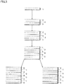
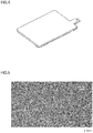
- the electrode plate is manufactured by using an aluminum plate of Fig. 4 and, in an inner portion of the plating layers, a plating layer made of lead or lead alloy with fine compositions is formed by performing processes of Fig. 3 to improve the adhesion and corrosion resistance. In an outer portion of the plating layers, a plating layer which is made of lead or lead alloy and which is rough and has a large surface area is formed to improve charging and discharging performances.
- a surface of aluminum is covered with a strong oxide layer and a plating layer cannot be attached thereto with good adhesion. Accordingly, before the formation of the plating layer made of lead or lead alloy, appropriate surface preparation is performed on the aluminum surface to improve the adhesion of the plating layer.
- a method such as anodization, electroless nickel plating, or tin substitution plating can be selected as the surface preparation. In this step, the electroless nickel plating is employed to activate a plating surface and improve the adhesion of the lead plating layer made of lead or lead alloy.
- the aluminum plate subjected to the surface preparation is immersed in one of plating baths of a fluorosilicate bath, a fluoborate bath, and an organic acid bath or a combination of two or more of these plating baths.
- a fluorosilicate bath a fluoborate bath
- an organic acid bath or a combination of two or more of these plating baths a plating bath to which an organic additive such as gelatin or peptone is added by 0.1 g/L to 5 g/L to improve uniform electrodeposition properties.
- the plate is rocked in an up-down direction while the bath is uniformly agitated with a current applied for 60 minutes to 150 minutes at a current density of 0.5 A/dm 2 to 20 A/dm 2 by using lead with a purity of 99.99% or lead alloy as an anode.
- a pinhole-free lead plating layer is thereby laminated on the aluminum plate.
- the lead plating layer of at least lead or lead alloy can be laminated to have a thickness of 200 ⁇ m or more by changing the concentration, the current application time, the temperature, the current density, and the current waveform, the plating thickness is set to 30 ⁇ m to 200 ⁇ m in both of the positive electrode plate and the negative electrode plate in consideration of the uniformness of the surface and an increase in mass.
- a positive electrode terminal, a negative electrode terminal, and an electrode plate group stripe are also formed to have a similar plating thickness.
- the lead plating layer made of lead is a plating layer having a metal composition containing lead at a purity of 99.99% or more and the lead plating layer made of lead alloy is a plating layer having a metal composition containing lead at a purity of 95% or more, preferably, a plating layer having a metal composition containing lead at a purity of 97% or more, and more preferably a plating layer having a metal composition containing lead at a purity of 99% at maximum.
- the lead plating layer made of lead is a plating layer having a metal composition containing lead at a purity of 99.99% or more and the lead plating layer made of lead alloy is a plating layer having a metal composition containing lead at a purity of 95% or more, preferably, a plating layer having a metal composition containing lead at a purity of 97% or more, and more preferably a plating layer having a metal composition containing lead at a purity of 99% at maximum.
- a final plating surface is formed to be a coarse lead film to increase the surface area.
- the charging and discharging performances of the positive electrode active material or the negative electrode active material to be generated by electrolytic formation treatment using dilute sulfuric acid are thereby improved.
- a current is continuously applied at a current density of 0.1 A/dm 2 to 10 A/dm 2 by using a lead plate or an insoluble electrode in dilute sulfuric acid with specific gravity of 1.01 to 1.30. Then, the current is reversed every 6 hours to 12 hours.
- the final current application is finished with the electrode plate being the anode and a dark brown positive electrode active material is thereby made to deposit on the surface of the lead plating layer.
- the final current application is performed in a similar method with the electrode plate being the cathode and a gray negative electrode active material is thereby made to deposit on the surface of the lead plating layer.
- the positive electrode plate or the negative electrode plate on which the active material is generated is sufficiently washed under running water and dried by hot air. Then, the plate is left as it is for 24 hours or more to be matured and the positive electrode plate or the negative electrode plate is thus obtained.
- the positive electrode terminal, the negative electrode terminal, and the electrode plate group stripe are subjected to plating similar to that for the negative electrode plate to provide resistance against corrosion caused by dilute sulfuric acid mist and are not subjected to the electrolytic formation treatment.
- a discharging test is performed by connecting a light bulb of 2.5V, 0.5A to the aforementioned single cell and lighting the light bulb.
- the mass increase was 4.93 g and the plate thickness increase was 0.04 mm.
- the mass increase was 7.44 g and the plate thickness increase was 0.06 mm.
- the mass increase was 12.56 g and the plate thickness increase was 0.1 mm.
- the mass increase was 20.27 g and the plate thickness increase was 0.16 mm.
- the average mass and average plate thickness of the current paste-type positive electrode plates (Comparative Examples 1 to 5) and negative electrode plates (Comparative Examples 6 to 10) are compared with those of the aluminum thin plate subjected to the lead plating in Example 4 by using Table 2.
- the average mass of the paste-type positive electrode plates is 83.8 g and the plate thickness thereof is 1.156 mm. Meanwhile, in the electrode plate of Example 4 to which lead alloy (solder plating layer) and lead (lead plating layer) are attached, the average mass is 32.44 g and the plate thickness is 0.42 mm and the weight and thickness are reduced.
- the negative electrode plates are compared with Example 4 and weight reduction from the average mass of 73.8 g to 32.44 g and thickness reduction from the plate thickness of 1.156 mm to 0.42 mm are achieved.
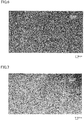
- the surface of the lead plating layer in Fig. 5 had a greater surface area than a current lead plate surface in Fig. 9 . Accordingly, the surface areas of the positive electrode active material and the negative electrode active material generated in the positive electrode plate and the negative electrode plate after the electrolytic formation treatment also increased and the discharging time in a state where the single cell was assembled increased by 18% in comparison with the positive electrode plate and the negative electrode plate formed of the lead plates.
- an electrode body 21 of a lead-acid battery according to a second embodiment of the present invention is described in detail based on the drawings. Note that, in the description of the embodiment, the same members are denoted by the same reference numerals in principle and overlapping description is omitted. Moreover, in the following description, the first embodiment described by using Figs. 1 to 12 is referred to as appropriate.
- Fig. 13A is a perspective view explaining the electrode body 21 of the lead-acid battery in the embodiment.
- Fig. 13B is a cross-sectional view of the electrode body 21 in the line A-A direction illustrated in Fig. 13A .
- a plate-shaped base member 22 (see Fig. 13B ) having a shape illustrated in Fig. 4 and made of aluminum or aluminum alloy is used for the electrode body 21.
- the base member 22 has, for example, a plate thickness of 0.2 mm and a mass of 5.98 g. Note that the plate thickness of the base member 22 only needs to be 0.15 mm or more and is preferably 1.0 mm or less from the viewpoint of weight reduction of the electrode body.
- Multiple plating layers 23 are formed on a surface of the base member 22.
- First and second lead plating layers 27, 28 located in an outer surface portion of the multiple plating layers 23 are subjected to electrolytic formation treatment to form an active material layer 24.
- the first and second lead plating layers 27, 28 are plating layers obtained by laminating lead plating layers made of at least lead or lead alloy by using a plating technique as in the aforementioned first embodiment.
- the electrode body 21 is used as the positive electrode plate or the negative electrode plate of the lead-acid battery.
- the active material layer 24 is a dark brown positive electrode active material layer.
- the active material layer 24 is a gray negative electrode active material layer.
- the surface roughness Ra of the second lead plating layer 28 is 0.500 ⁇ m or more and 40.000 ⁇ m or less. Due to this structure, the active material layer 24 formed on the second lead plating layer 28 has a large surface area and the charging and discharging performances of the lead-acid battery are improved.
- the electrode body 21 includes the base member 22, a nickel plating layer 25 covering the surface of the base member 22, a solder plating layer 26 covering a surface of the nickel plating layer 25, the first lead plating layer 27 covering a surface of the solder plating layer 26 and having a fine metal composition, the coarse second lead plating layer 28 covering a surface of the first lead plating layer 27 and having a rougher metal composition than the first lead plating layer 27, and the active material layer 24 formed by at least partially subjecting the first and second lead plating layers 27, 28 to the electrolytic formation treatment.
- the solder plating layer 26 in the embodiment is a plating layer having such a metal composition that the ratio (mass ratio) of lead to tin is 9:1 at maximum and 5:5 at minimum.
- a current collector lattice made of lead alloy is used as a frame of the electrode plate. Moreover, spaces in the current collector lattice are filled with, as the active material, paste obtained by kneading lead powder made of lead oxide and metal lead with water and dilute sulfuric acid or a paste obtained by kneading these substances with a reinforcement agent such as fibers.
- the base member 22 of the electrode body 21 is changed from the conventional current collector lattice made of lead alloy to one made of aluminum or aluminum alloy with small specific gravity to achieve the mass and thickness reduction of each electrode body 21.
- the solder plating layer 26 is formed as a measure against the pinholes in the multiple plating layers 23 on the surface of the base member 22.
- the solder plating layer 26 is formed to have a film thickness of at least 10 ⁇ m or more.
- the present inventors focused on presence of a recess portion made by a dent or a scratch formed on the base member 22 in transport or manufacturing processing, as a mechanism forming the pinholes.
- the base member 22 is a soft-material thin plate member made of aluminum or aluminum alloy and the aforementioned recess portion is likely to be formed. It was found that, when the multiple plating layers 23 are formed on the surface of the base member 22 with the recess portion formed on the surface of the base member 22, the recess portion cannot be sufficiently buried by the solder plating layer 26 if the film thickness of the solder plating layer 26 is less than 10 ⁇ m, and the pinholes are formed above the recess portion in the first and second lead plating layers 27, 28.
- Fig. 14 illustrates a result of a test in which single cells with the same structure as one used in the discharging test described by using Fig. 8 were formed and a discharging test was performed. Specifically, five positive electrode plates in which the active material layers 24 of the electrode bodies 21 were the positive electrode active material layers were prepared and were each covered with a separator. Meanwhile, six negative electrode plates in which the active material layers 24 of the electrode bodies 21 were the negative electrode active material layers were prepared. Then, the aforementioned positive electrode plates and the negative electrode plates are alternately stacked and the positive electrode terminal and the negative electrode terminal were attached to the stacked body to form the single cell.
- Dilute sulfuric acid with specific gravity of 1.01 to 1.30 was injected into the single cell and the single cell was left as it is until heat generation stopped. Then the cell was charged for 24 hour or more at a constant voltage of 2.2 V to 2.7 V and a single cell battery with a nominal voltage of 2 V was thus manufactured. After the completion of charging, the discharging test was performed by connecting a light bulb of 2.5V, 0.5A to the aforementioned single cell and lighting the light bulb.
- the laminated plating film thickness illustrated in Fig. 14 is a film thickness of the laminated solder plating layer 26, first lead plating layer 27, and second lead plating layer 28.
- the film thickness ratio in the electrode body 21 is not limited to this film thickness ratio and any design change can be made depending on the battery capacity and specifications of the lead-acid battery and the like.
- the film thickness of the solder plating layer 26 is 6.2 ⁇ m at maximum according to the aforementioned film thickness ratio and the film thickness of the solder plating layer 26 is less than 10 ⁇ m.
- pinholes were formed in at least one of the positive electrode plate and the negative electrode plate and the discharging times of Examples 8 to 10 were 24 minutes, 46 minutes, and 68 minutes, respectively, and Examples 8 to 10 failed to achieve a sufficient discharging time. This is due to the following reason.
- dilute sulfuric acid in the step of generating the active material layer 24 or dilute sulfuric acid in the discharging testing enters from the pinholes and dissolves the nickel plating layer 25 and the solder plating layer 26 below the pinholes to corrode the base member 22.
- a leak current is generated from a corrosion region of the base member 22 and the capacity as a lead-acid battery decreases.
- the film thickness of the solder plating layer 26 is 8.0 ⁇ m at minimum and 9.1 ⁇ m at maximum according to the aforementioned film thickness and is less than 10 ⁇ m.
- the formation of pinholes was suppressed.
- the film thickness of the solder plating layer 26 is 13.7 ⁇ m at minimum and 14.8 ⁇ m at maximum and is 10 ⁇ m or more. In this case, the formation of pinholes was suppressed.
- the film thickness of the solder plating layer 26 is preferably 10 ⁇ m or more in consideration of defects occurring in mass production.
- solder plating layer 26 does not have an excellent property of covering (property of burying) the aforementioned recess portion, laminating the solder plating layer 26 8 ⁇ m or more, preferably 10 ⁇ m or more can compensate for the covering property and burry the recess portion to such a level that the formation of pinholes above the recess portion in the first and second lead plating layers 27, 28 can be suppressed.
- the discharging time increases with an increase in the laminated plating film thickness.
- the increase amount thereof is small. This is because, in the current technique of generating the active material, the discharging time saturates when the film thickness of the active material layer 24 reaches a certain value or more and there is a room for further research in film properties of active material and the like. Note that, in Examples 13 and 14, the energy density per mass of the lead-acid battery is equivalent to that of a nickel hydride battery.
- the solder plating layer 26 also contains a lead component and can thus stop the corrosion by dilute sulfuric acid to some extent. Accordingly, it is desirable to increase the film thickness of the solder plating layer 26. Meanwhile, increasing the film thickness of the first and second lead plating layers 27, 28 and making the active material layer 24 thick leads to an increase in the discharging time. Thus, any design changes can be made to the relationships between the film thickness of the solder plating layer 26 and the film thickness of the first and second lead plating layers 27, 28 depending on the specifications of the lead-acid battery and the like.
- a thin-plate-shaped base member 22 having a shape illustrated in Fig. 4 and made of aluminum or aluminum alloy is prepared.
- a surface of aluminum forming the base member 22 is covered with a strong oxide layer and cannot be plated with good adhesion.
- surface preparation is performed on the base member 22.
- a method such as anodization, electroless nickel plating, or tin substitution plating can be selected as the surface preparation.
- an aluminum oxide film on the surface of the base member 22 is removed by publicly-known syndicate processing and then electroless nickel plating is employed to form the nickel plating layer 25 covering the surface of the base member 22.
- the film thickness of the nickel plating layer 25 is about 1 ⁇ m or more and 5 ⁇ m or less and the nickel plating layer 25 has excellent uniform electrodeposition properties and is firmly formed also on the aforementioned recess portion of the base member 22.
- solder plating layer 26 covering the nickel plating layer 25 on the surface of the base member 22 is formed.
- the solder plating layer 26 can be formed by using one of plating baths of a fluorosilicate bath, a fluoborate bath, and an organic acid bath or a combination of two or more of these plating baths.
- the fluoborate bath is used and a solder plating liquid to which an organic additive such as gelatin or peptone is added by 1 g/L to 20 g/L to improve uniform electrodeposition properties and which is composed mainly of 2 g/L to 10 g/L metal tin, 90 g/L to 98 g/L metal lead, and 100 g/L to 250 g/L fluoroboric acid in terms of concentration is used.
- an organic additive such as gelatin or peptone
- the plate is rocked in an up-down direction while the bath is uniformly agitated with a current applied for 10 minutes to 60 minutes at a current density of 1 A/dm 2 to 20 A/dm 2 by using an anode electrode in which the ratio (mass ratio) between lead and tin is 9:1.
- the pinhole-free solder plating layer 26 is thereby laminated on the surface of the nickel plating layer 25. Note that, as described above, the plating processing is performed such that the film thickness of the solder plating layer 26 reaches at least 10 ⁇ m or more, in consideration of the covering property (burying property) of the solder plating. Moreover, when the aforementioned solder plating liquid is used, the solder plating layer 26 having such a metal composition that the ratio (mass ratio) between lead and tin is 9:1 is formed.
- the first lead plating layer 27 and the second lead plating layer 28 made of lead or lead alloy and covering the solder plating layer 26 on the surface of the base member 22 are formed.
- the first lead plating layer 27 and the second lead plating layer 28 can be formed by using one of plating baths of a fluorosilicate bath, a fluoborate bath, and an organic acid bath or a combination of two or more of these plating baths.
- the fluoborate bath is used and a lead plating liquid to which an organic additive such as gelatin or peptone is added by 1 g/L to 20 g/L to improve uniform electrodeposition properties and which is composed mainly of 100 g/L to 150 g/L metal lead and 100 g/L to 200 g/L fluoroboric acid in terms of concentration is used.
- the plate is rocked in an up-down direction while the bath is uniformly agitated with a current applied for 10 minutes to 100 minutes at a current density of 1 A/dm 2 to 20 A/dm 2 by using lead and lead alloy with a purity of 99.99% as an anode.
- the pinhole-free first lead plating layer 27 is thereby laminated on the surface of the solder plating layer 26.
- the first lead plating layer 27 having a metal composition containing lead at a purity of 99.99% or more is formed.
- a plating layer made of lead-tin alloy having a metal composition containing lead at a purity of 95% or more, preferably 97% or more may be formed as the first lead plating layer 27.
- the fluoborate bath is used and a lead plating liquid to which an organic additive such as gelatin or peptone is added by 1 g/L to 20 g/L to improve uniform electrodeposition properties and which is composed mainly of 80 g/L to 120 g/L metal lead and 150 g/L to 300 g/L fluoroboric acid in terms of concentration is used.
- the plate is rocked in an up-down direction while the bath is uniformly agitated with a current applied for 10 minutes to 100 minutes at a current density of 1 A/dm 2 to 20 A/dm 2 by using lead and lead alloy with a purity of 99.99% as an anode.
- the pinhole-free second lead plating layer 28 is thereby laminated on the surface of the first lead plating layer 27.
- the second lead plating layer 28 having a metal composition containing lead at a purity of 99.99% or more is formed.
- a plating layer made of lead-tin alloy having a metal composition containing lead at a purity of 95% or more, preferably 97% or more may be formed as the second lead plating layer 28.
- the surface roughness Ra of the first lead plating layer 27 is, for example, 0.05 ⁇ m or more and less than 5.000 ⁇ m
- the surface roughness Ra of the second lead plating layer 28 is, for example, 5.000 ⁇ m or more and 50.000 ⁇ m or less
- the surface roughness of the second lead plating layer 28 is greater than the surface roughness of the first lead plating layer 27. This is achieved by, for example, setting the temperature of the plating liquid for forming the second lead plating layer 28 lower than the temperature of the plating liquid for forming the first lead plating layer 27 and performing plating at a high current density of 10 A/dm 2 or more.
- the film thickness of the solder plating layer 26 and the first and second lead plating layers 27, 28 can be made equal to or greater than 200 ⁇ m by changing the concentration, the current application time, the temperature, the current density, and the current waveform, the film thickness is set to 30 ⁇ m or more and 200 ⁇ m or less in both of the positive electrode plate and the negative electrode plate in consideration of the uniformness of the surface and an increase in mass,.
- the weight reduction of the lead-acid battery is achieved by forming the nickel plating layer 25, the solder plating layer 26, and the first and second lead plating layers 27, 28 on the surface of the base member made of aluminum or aluminum alloy similarly in the positive electrode terminal, the negative electrode terminal, and the electrode plate group stripe of the lead-acid battery.
- the active material layer 24 is formed on the surface of the first and second lead plating layers 27, 28 by electrolytic formation treatment.
- the current is continuously applied at a current density of 0.1 A/dm 2 to 10 A/dm 2 by using a lead plate or an insoluble electrode in dilute sulfuric acid with specific gravity of 1.01 to 1.30. Then, the current is reversed every 6 hours to 12 hours.
- the base member 22 to be used as the positive electrode plate the final current application is performed with the base member 22 being the anode and a dark brown positive electrode active material is thereby made to deposit on the surface of the lead plating layer.
- the final current application is performed in a similar method with the base member 22 being the cathode and a gray negative electrode active material is thereby made to deposit on the surface of the lead plating layer.
- the base member 22 on which the active material is formed is sufficiently washed under running water and dried by hot air. Then, the base member 22 is left as it is for 24 hours or more to be matured and the positive electrode plate or the negative electrode plate is thus obtained.
- the plating is performed while reversing the current during the plating steps by using a pulse power source or a PR power source to prevent a projecting object from causing short-circuit in a plating outer peripheral surface and to achieve an uniform plating film thickness.
- the present invention is not limited to this case and may be as follows: for example, the oxide film on the surface of the base member 22 is treated as in the first embodiment; and as a pre-process of forming the nickel plating layer 25, for example, the recess portion made by a dent or the like on the surface of the base member 22 is removed by using a very fine 3000 grit sandpaper and a flat surface is thereby formed on the surface of the base member 22.
- a chemical polishing process may be used as a method of removing the aforementioned recess portion on the surface of the base member 22.
- effects such as the weight reduction and size reduction of the entire lead-acid battery and an improvement in energy density can be obtained by similarly manufacturing the positive electrode terminal, the negative electrode terminal, and the electrode plate group stripe which are components of the lead-acid battery other than the positive electrode plate and the negative electrode plate by using an aluminum material and forming the solder plating layer 26 and the first and second lead plating layers 27, 28 on the surface of the aluminum material.
- subjecting the positive electrode terminal, the negative electrode terminal, and the electrode plate group stripe to the aforementioned plating processing can prevent corrosion caused by dilute sulfuric acid mist generated in the charging and discharging processes of the lead-acid battery during use of the lead-acid battery.
- effects such as reduction of fall-off of the active material layer 24 achieved by the improvement in adherence and saving of resources achieved by collecting and reusing metals and chemicals through collection and recycling of the plating liquid can be obtained as in the first embodiment.
- an electrode body 41 of a lead-acid battery according to a third embodiment of the present invention is described in detail based on the drawings.
- the electrode body 41 of the third embodiment is different from the electrode body 21 of the second embodiment mainly in that the electrode body 41 has a structure in which a tin plating layer 43 is formed between the nickel plating layer 25 and the solder plating layer 26. Accordingly, in the following description, when the electrode body 41 is described, the same members as those in the second embodiment are denoted by the same reference numerals in principal and overlapping description is omitted. Moreover, as in the description of the second embodiment, the first embodiment described by using Figs. 1 to 12 is referred to as appropriate.
- Fig. 15A is a perspective view explaining the electrode body 41 of the lead-acid battery in the embodiment.
- Fig. 15B is a cross-sectional view of the electrode body 41 in the line B-B direction illustrated in Fig. 15A .
- the thin plate-shaped base member 22 having a shape illustrated in Fig. 4 and made of aluminum or aluminum alloy is used for the electrode body 41. Then, multiple plating layers 42 are formed on the surface of the base member 22.
- the first and second lead plating layers 27, 28 located in the outer surface portion of the multiple plating layers 42 are at least partially subjected to electrolytic formation treatment to form the active material layer 24.
- the electrode body 41 includes the base member 22, the nickel plating layer 25 covering the surface of the base member 22, the tin plating layer 43 covering the surface of the nickel plating layer 25 and made of tin or tin-lead alloy, the solder plating layer 26 covering a surface of the tin plating layer 43, the first lead plating layer 27 covering the surface of the solder plating layer 26 and having a fine metal composition, the second lead plating layer 28 covering the surface of the first lead plating layer 27 and having the rougher metal composition than the first lead plating layer 27, and the active material layer 24 formed by at least partially subjecting the first and second lead plating layers 27, 28 to the electrolytic formation treatment.
- many layers of group 4 metals with similar chemical properties are laminated to prevent the formation of pinholes and achieve improvements in adhesion and corrosion resistance.
- the tin plating layer 43 is a plating film formed as a measure against the pinholes as described also in the second embodiment and is formed on the surface of the nickel plating layer 26. Moreover, the tin plating layer 43 is a film with excellent covering property (burying property). The film thickness of the tin plating layer 43 is set to 1 ⁇ m or more and the upper limit value thereof is preferably set to 10 ⁇ m from the viewpoint of weight reduction. This allows the tin plating layer 43 to burry a step formed by the recess portion made by a dent or a scratch formed on the surface of the base member 22 and prevent the formation of pinholes in the multiple plating layers 42 located above the tin plating layer 43.
- the tin plating layer made of tin is a plating layer having a metal composition containing tin at a purity of 99.99% or more.
- the plating layer made of tin-lead alloy is an alloy plating layer of lead and tin containing tin at a purity of 95% or more, preferably an alloy plating layer of lead and tin containing tin at a purity of 97% or more, more preferably an alloy plating layer of lead and tin containing tin at a purity of 99% at maximum. The same applies to the following description.
- Fig. 16 illustrates a result of a test in which single cells with the same structure as one used in the discharging test described by using Fig. 8 were formed and a discharging test was performed. Specifically, five positive electrode plates using the active material layer 24 of the electrode body 41 as the positive electrode active material layer were prepared and were each covered with a separator. Meanwhile, six negative electrode plates using the active material layer 24 of the electrode body 41 as the negative electrode active material layer were prepared. Then, the aforementioned positive electrode plates and the negative electrode plates were alternately stacked and the positive electrode terminal and the negative electrode terminal were attached to the stacked body to form the single cell. Dilute sulfuric acid with specific gravity of 1.01 to 1.30 was injected into the single cell and the single cell was left as it is until heat generation stopped.
- the cell was charged for 24 hour or more at a constant voltage of 2.2 V to 2.7 V and a single cell battery with a nominal voltage of 2 V was thus manufactured.
- a discharging test was performed by connecting a light bulb of 2.5V, 0.5A to the aforementioned single cell and lighting the light bulb.
- the laminated plating film thickness illustrated in Fig. 15 is a film thickness of the laminated tin plating layer 43, solder plating layer 26, first lead plating layer 27, and second lead plating layer 28.
- the film thickness ratio in the electrode body 41 is not limited to this film thickness ratio and any design change can be made depending on the specifications of the lead-acid battery and the like.
- the film thickness of the tin plating layer 43 is 0.8 ⁇ m at minimum and 1.2 ⁇ m at maximum and is about 1 ⁇ m and it is found that at least the plating layer 43 having the film thickness of 1 ⁇ m can bury the aforementioned recess portion on the surface of the base member 22 and suppress the formation of pinholes. Note that, although the film thickness of the tin plating layer 43 is increased in Examples 19 to 29, any design changes can be made to the film thickness of the tin plating layer 43 in consideration of stability of quality in mass production of the electrode body 41.
- Example 19 to 27 the discharging time increases with an increase in the laminated plating film thickness. Meanwhile, in Examples 28 to 29, although the discharging time increases with the increase in the laminated plating film thickness, the increase amount thereof is small. Note that, in Example 24, the energy density per mass of the lead-acid battery is equivalent to that of a nickel hydride battery.
- Example 26 are preferable for conditions taking in consideration of the weight reduction and thickness reduction of the electrode body 41 based on a relationship with the average mass of the electrode body 41.
- the laminated plating film thickness is about 150 ⁇ m and, for example, the film thickness of the tin plating layer 43 is about 30 ⁇ m.
- setting the film thickness of the tin plating layer 43 to 30 ⁇ m or less, more preferably 10 ⁇ m or less can achieve weight reduction while the solder plating layer 26 and the first and second lead plating layers 27, 28 are made to have large film thicknesses.
- the solder plating layer 26 also contains a lead component and can thus stop the corrosion by dilute sulfuric acid to some extent. Accordingly, it is desirable to increase the film thickness of the solder plating layer 26. Meanwhile, increasing the film thickness of the first and second lead plating layers 27, 28 and making the active material layer 24 thick leads to an increase in the discharging time. Thus, any design changes can be made to the relationships between the film thickness of the solder plating layer 26 and the film thicknesses of the first and second lead plating layers 27, 28 depending on the specifications of the lead-acid battery and the like.
- steps of manufacturing the electrode body 41 in the third embodiment of the present invention is described with reference to Fig. 15B .
- the method of plating is not limited to the steps in the present invention as long as the method does not depart from the spirit of the present invention.
- the steps of manufacturing the electrode body 41 are the same as those described in the second embodiment except for the point that a step of forming the tin plating layer 43 is newly added as (Step X) between (Step 2) and (Step 3) described in the second embodiment. In this embodiment, only the step of forming the tin plating layer 43 is described while referring to the description of the second embodiment.
- the tin plating layer 43 covering the nickel plating layer 25 is formed.
- the tin plating layer 43 can be formed by using one of plating baths of an alkanolsulfonate bath, a phenolsulfonate bath, a fluoborate bath, and a sulfate bath or a combination of two or more of these baths.
- the sulfate bath is used and a tin plating liquid to which an organic additive such as gelatin or peptone is added by 20 g/L to 50 g/L to improve uniform electrodeposition properties and which is composed mainly of 20 g/L to 80 g/L stanous sulfate and 50 g/L to 200 g/L sulfuric acid in terms of concentration is used.
- the plate is rocked in an up-down direction while the bath is uniformly agitated with current applied for 10 minutes to 40 minutes at a current density of 1 A/dm 2 to 10 A/dm 2 .
- the pinhole-free tin plating layer 43 is thereby laminated on the surface of the nickel plating layer 25.
- the tin plating layer 43 having a metal composition with a purity of 99.99% or more is formed.
- the plating is performed while reversing the current during the plating step by using a pulse power source or a PR power source to prevent a projecting object from causing short-circuit in a plating outer peripheral surface and to achieve an uniform plating film thickness.
- the present invention is not limited to this case and may be as follows: for example, the oxide film on the surface of the base member 22 is treated as in the first embodiment; and as a pre-process of forming the nickel plating layer 25, for example, the recess portion made by a dent or the like on the surface of the base member 22 is removed by using a very fine 3000 grit sandpaper and a flat surface is thereby formed on the surface of the base member 22.
- a chemical polishing process may be used as a method of removing the aforementioned recess portion on the surface of the base member 22.
- effects such as the weight reduction and size reduction of the entire lead-acid battery and an improvement in energy density can be obtained by similarly manufacturing the positive electrode terminal, the negative electrode terminal, and the electrode plate group stripe which are components of the lead-acid battery other than the positive electrode plate and the negative electrode plate by using an aluminum material and forming the tin plating layer, the solder plating layer, and the lead plating layer on the surface of the aluminum material.
- subjecting the positive electrode terminal, the negative electrode terminal, and the electrode plate group stripe to the aforementioned plating processing can prevent corrosion caused by dilute sulfuric acid mist generated in the charging and discharging processes of the lead-acid battery during use of the lead-acid battery.
- effects such as reduction of fall-off of the active material layer 24 achieved by the improvement in adherence and saving of resources achieved by collecting and reusing metals and chemicals through collection and recycling of the plating liquid can be obtained as in the first embodiment.
- the lead plating layers are formed as two plating layers of the first lead plating layer 27 with the fine composition and the second lead plating layer 28 with the rougher composition than the first lead plating layer 27.
- the lead plating layer may be formed of a single layer of the first lead plating layer 27 or the second lead plating layer 28.
- the lead plating layers may be formed as three or more films laminated one on top of another. In this case, the charging and discharging performances of the lead-acid battery can be improved by making the film quality of the outermost plating film roughest and thereby increasing the surface area of the active material layer 24.
- the active material layer is formed by generating the positive electrode active material or the negative electrode active material by electrolytic formation treatment on the lead plating layer formed on the aluminum or aluminum alloy base member.
- the present invention is not limited to this.
- an electrode plate of a type using an unconverted paste-form active material may be manufactured by applying the aforementioned active material paste and performing preheating drying, maturing, and drying.
- various changes can be made within a scope not departing from the spirit of the present invention.
- the present invention is used in the industry manufacturing lead-acid batteries.
- the components of the lead-acid battery such as the positive electrode plate, the negative electrode plate, the electrode terminals, and the electrode plate group stripe are manufactured by using aluminum or aluminum alloy which has low specific gravity and high electrical conductivity. Accordingly, it is possible to greatly reduce the weight and the usage amount of lead and greatly improve the energy density which is about 35 KH/kg in a current lead-acid battery.
- the volume resistance of lead is 20.8 ⁇ 10 -8 ⁇ m while the volume resistance of aluminum is about 2.8 ⁇ 10 -8 ⁇ m and aluminum has lower resistance than lead.
- the multiple plating layers 23, 42 are entirely formed on the base member 22 made of aluminum. Accordingly, the positive electrode plate and the negative electrode plate each have a large contact area as the current collector lattice and the charging efficiency of the lead-acid battery is thus improved.
- the pinholes formed in the process of manufacturing the components of the lead-acid battery such as the positive electrode plate and the negative electrode plate and in the use of the lead-acid battery are prevented by the method of laminating many layers of group 4 metals by using the electrolyte plating method.
- the electrolyte lead plating in which the final lead plating layer is formed to have a surface roughness Ra of 0.500 ⁇ m to 40.000 ⁇ m is performed to increase the surface area and then the positive electrode active material or the negative electrode active material is generated on the lead plating layer by using the electrolytic formation treatment using dilute sulfuric acid.
- the weight and thickness can be reduced compared to the conventional dry manufacturing method in which the lattice made of lead alloy is filled with the lead powder paste obtained by kneading fine lead powder and sulfuric acid. Moreover, there is no dispersal of fine lead powder and this contributes to improvements in a working environment in a manufacturing site. Moreover, in the plating step, the collection rate and the reuse rate of tin and lead are high and this contributes to reduction of manufacturing cost.
- the aluminum base member with excellent conductivity is used inside the electrode plates and the like and the surface areas of the electrode plates and the like are large, the charging efficiency is improved and the charging speed can be improved from that in the current lead-acid battery in which the lead alloy lattice is filled with the lead paste.
- the energy density is improved by the weight reduction and the thickness reduction and the present invention can be expected to sufficiently contribute not only to cars and transport vehicles but also to a large-scale storage battery in a large uninterruptable power supply, a reusable energy power storage system, and the like as a high performance lead-acid battery.
- the present invention improves the energy density of the lead-acid battery which is safe and has a long history and thereby contributes greatly to an improvement in fuel efficiency achieved by weight reduction of a vehicle body.
- the present invention contributes to comprehensive technical development as a basic component part for the electrification of the vehicle in the future and thus has an industrial utility value including environmental measures.
Landscapes
- Chemical & Material Sciences (AREA)
- Chemical Kinetics & Catalysis (AREA)
- Electrochemistry (AREA)
- General Chemical & Material Sciences (AREA)
- Engineering & Computer Science (AREA)
- Materials Engineering (AREA)
- Manufacturing & Machinery (AREA)
- Cell Electrode Carriers And Collectors (AREA)
- Battery Electrode And Active Subsutance (AREA)
- Connection Of Batteries Or Terminals (AREA)
Applications Claiming Priority (2)
| Application Number | Priority Date | Filing Date | Title |
|---|---|---|---|
| JP2017252385 | 2017-12-11 | ||
| PCT/JP2018/038209 WO2019116712A1 (ja) | 2017-12-11 | 2018-10-12 | 鉛蓄電池の電極体及びそれを用いた鉛蓄電池 |
Publications (2)
| Publication Number | Publication Date |
|---|---|
| EP3598539A1 true EP3598539A1 (de) | 2020-01-22 |
| EP3598539A4 EP3598539A4 (de) | 2021-03-24 |
Family
ID=66820134
Family Applications (1)
| Application Number | Title | Priority Date | Filing Date |
|---|---|---|---|
| EP18887921.7A Withdrawn EP3598539A4 (de) | 2017-12-11 | 2018-10-12 | Elektrodenkörper für bleiakkumulator und denselben verwendender bleiakkumulator |
Country Status (5)
| Country | Link |
|---|---|
| US (1) | US11342550B2 (de) |
| EP (1) | EP3598539A4 (de) |
| JP (1) | JP6713137B2 (de) |
| CN (1) | CN110546791B (de) |
| WO (1) | WO2019116712A1 (de) |
Families Citing this family (2)
| Publication number | Priority date | Publication date | Assignee | Title |
|---|---|---|---|---|
| CN111801813B (zh) | 2018-03-05 | 2023-10-24 | Cps科技控股有限公司 | 电池端子 |
| CN117832515B (zh) * | 2023-12-20 | 2025-10-31 | 天能电池集团(马鞍山)新能源科技有限公司 | 一种铅酸蓄电池板栅及其制造方法 |
Family Cites Families (22)
| Publication number | Priority date | Publication date | Assignee | Title |
|---|---|---|---|---|
| JPS509538Y1 (de) | 1969-06-05 | 1975-03-24 | ||
| JPS509538B1 (de) * | 1969-12-23 | 1975-04-14 | ||
| JPS5038171B1 (de) | 1971-03-29 | 1975-12-08 | ||
| JPS5341615B2 (de) * | 1973-05-30 | 1978-11-06 | ||
| JPS59191561A (ja) * | 1983-04-13 | 1984-10-30 | Showa Alum Corp | アルミニウムと鉛の複合材及びその製造方法 |
| JPS59191561U (ja) * | 1983-06-08 | 1984-12-19 | アイシン精機株式会社 | 逆スタ−リング冷凍機 |
| JPS6025153A (ja) * | 1983-07-21 | 1985-02-07 | Yuasa Battery Co Ltd | 鉛蓄電池 |
| JPS632253A (ja) | 1986-06-20 | 1988-01-07 | Yuasa Battery Co Ltd | 鉛蓄電池及びその製造法 |
| JPS63174276A (ja) | 1987-01-09 | 1988-07-18 | Japan Storage Battery Co Ltd | 鉛電池用格子体 |
| JPH05299094A (ja) | 1992-04-16 | 1993-11-12 | Tokai Rubber Ind Ltd | 鉛蓄電池用複合格子 |
| JPH05343049A (ja) | 1992-06-09 | 1993-12-24 | Mitsui Eng & Shipbuild Co Ltd | 複極板および鉛蓄電池 |
| JPH11111275A (ja) | 1997-09-30 | 1999-04-23 | Yuasa Corp | 鉛蓄電池用極板の製造方法 |
| US6566010B1 (en) | 2000-11-16 | 2003-05-20 | Concorde Battery Corporation | High energy, lightweight, lead-acid storage battery |
| JP2002313347A (ja) * | 2001-04-11 | 2002-10-25 | Matsushita Electric Ind Co Ltd | 鉛蓄電池用集電体とその鉛蓄電池用集電体を備えた鉛蓄電池 |
| US20040002006A1 (en) | 2002-06-28 | 2004-01-01 | Caterpillar Inc. | Battery including carbon foam current collectors |
| CN101092707A (zh) | 2007-04-06 | 2007-12-26 | 昆明理工大学 | 铝-铅复合电极材料的制备方法 |
| JP2008287909A (ja) | 2007-05-15 | 2008-11-27 | Shin Kobe Electric Mach Co Ltd | 鉛蓄電池の製造方法 |
| CN101174692A (zh) * | 2007-10-31 | 2008-05-07 | 深圳市今星光实业有限公司 | 一种铅酸蓄电池负极板栅合金 |
| JP5433144B2 (ja) * | 2007-11-12 | 2014-03-05 | 東京応化工業株式会社 | リチウム二次電池用負極基材 |
| CN101834295B (zh) * | 2010-05-27 | 2013-07-31 | 江苏华富控股集团有限公司 | 一种铅蓄电池负极板栅的制备方法 |
| US20130071735A1 (en) * | 2011-09-21 | 2013-03-21 | Hollingsworth & Vose Company | Battery components with leachable metal ions and uses thereof |
| CN107069042A (zh) * | 2017-05-15 | 2017-08-18 | 昆明理工恒达科技股份有限公司 | 一种铅酸蓄电池用轻型板栅及其制备方法 |
-
2018
- 2018-10-12 WO PCT/JP2018/038209 patent/WO2019116712A1/ja not_active Ceased
- 2018-10-12 CN CN201880025215.5A patent/CN110546791B/zh active Active
- 2018-10-12 JP JP2019558939A patent/JP6713137B2/ja active Active
- 2018-10-12 EP EP18887921.7A patent/EP3598539A4/de not_active Withdrawn
- 2018-10-12 US US16/614,137 patent/US11342550B2/en active Active
Also Published As
| Publication number | Publication date |
|---|---|
| US20200106091A1 (en) | 2020-04-02 |
| WO2019116712A1 (ja) | 2019-06-20 |
| EP3598539A4 (de) | 2021-03-24 |
| US11342550B2 (en) | 2022-05-24 |
| JP6713137B2 (ja) | 2020-07-01 |
| CN110546791A (zh) | 2019-12-06 |
| CN110546791B (zh) | 2022-12-06 |
| JPWO2019116712A1 (ja) | 2020-05-28 |
Similar Documents
| Publication | Publication Date | Title |
|---|---|---|
| JP7030239B2 (ja) | 電着銅箔および電極ならびにそれを含むリチウムイオン二次電池 | |
| CN1184359C (zh) | 多孔铜箔及其用途和制造方法 | |
| CN100355131C (zh) | 集流体结构及改进铅-酸蓄电池性能的方法 | |
| TWI624986B (zh) | 可供改善蓄電池之電容量保留率的電解銅箔、電極、蓄電池、及其製造方法 | |
| CN101748451B (zh) | 轴瓦四元合金电镀工艺 | |
| TW201312839A (zh) | 鋰離子二次電池負極材之製造方法及鋰離子二次電池用負極材 | |
| KR100995886B1 (ko) | 니켈 도금된 리튬 이차 전지용 양극단자 및 그 제조 방법 | |
| JP2011241457A (ja) | 高耐食性を有する金属多孔体 | |
| CN100352099C (zh) | 包括碳泡沫集电体的蓄电池 | |
| CN106848198B (zh) | 一种锂电池负极极片的制备方法 | |
| CN103219523B (zh) | 一种铅酸蓄电池负极极板及其制备方法 | |
| Czerwiński et al. | Positive plate for carbon lead-acid battery | |
| KR20180110552A (ko) | 리튬 이온 2차전지, 이 2차전지의 음극 전극을 구성하는 집전체 및 이 음극 집전체를 구성하는 전해동박 | |
| US11342550B2 (en) | Electrode body for lead-acid battery, lead-acid battery using the same, and method of manufacturing electrode body for lead-acid battery | |
| CN108475790B (zh) | 铜箔及其制造方法、包括该铜箔的电极、包括该电极的二次电池 | |
| CN102660697A (zh) | 一种动力用铅酸蓄电池板栅合金 | |
| CN108598361A (zh) | 一种锂离子电池负极片及其制备方法、锂离子电池 | |
| KR20190069485A (ko) | 전지용 집전체 및 전지 | |
| JP6127289B2 (ja) | リチウムイオン電池用負極材料およびその製造方法 | |
| JP2010103061A (ja) | 二次電池用負極銅合金箔及び二次電池用負極銅合金箔の製造方法 | |
| CN103227316B (zh) | 一种铅酸蓄电池正极极板及其制备方法 | |
| US9837666B2 (en) | Cathode current collector for electrical energy storage device and method for manufacturing the same | |
| Wróbel et al. | Application of modified with copper porous carbon matrix on lead-acid battery | |
| KR101481107B1 (ko) | 마그네슘 이차전지용 양극 집전체 및 이의 제조 방법 | |
| CN102324523B (zh) | 一种硅液蓄电池 |
Legal Events
| Date | Code | Title | Description |
|---|---|---|---|
| STAA | Information on the status of an ep patent application or granted ep patent |
Free format text: STATUS: THE INTERNATIONAL PUBLICATION HAS BEEN MADE |
|
| PUAI | Public reference made under article 153(3) epc to a published international application that has entered the european phase |
Free format text: ORIGINAL CODE: 0009012 |
|
| STAA | Information on the status of an ep patent application or granted ep patent |
Free format text: STATUS: REQUEST FOR EXAMINATION WAS MADE |
|
| 17P | Request for examination filed |
Effective date: 20191014 |
|
| AK | Designated contracting states |
Kind code of ref document: A1 Designated state(s): AL AT BE BG CH CY CZ DE DK EE ES FI FR GB GR HR HU IE IS IT LI LT LU LV MC MK MT NL NO PL PT RO RS SE SI SK SM TR |
|
| AX | Request for extension of the european patent |
Extension state: BA ME |
|
| DAV | Request for validation of the european patent (deleted) | ||
| DAX | Request for extension of the european patent (deleted) | ||
| A4 | Supplementary search report drawn up and despatched |
Effective date: 20210224 |
|
| RIC1 | Information provided on ipc code assigned before grant |
Ipc: H01M 4/68 20060101ALI20210217BHEP Ipc: H01M 4/14 20060101AFI20210217BHEP |
|
| STAA | Information on the status of an ep patent application or granted ep patent |
Free format text: STATUS: THE APPLICATION HAS BEEN WITHDRAWN |
|
| 18W | Application withdrawn |
Effective date: 20240902 |